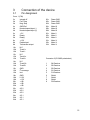
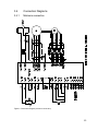
1
Pulse Width Modulated
4-Quadrant Servo Controller
Series TBF-R Installation Manual
For electronic commutated servo motors
2101 North Broadway
New Ulm, MN 56073
0199
Telephone: 507-354-1616
©MTS Automation 1999
Fax: 507-354-1611
Important!
Reading these instructions prior to start-up is absolutely necessary.
Dear customer,
The following items and the “Safety Instructions” are for your benefit and are designed to
protect the amplifier from damage caused by incorrect use. According to the product
liability law, everyone who puts a product which constitutes a risk for life and limb into
circulation is obligated to provide safety instructions. These instructions should be clearly
defined and should have an informative nature.
To assist you during installation, consider the following points:
•
•
•
•
•
•
2
Protect the amplifier from aggressive and electrically conductive media. These may
lead to a malfunction or destruction of the amplifier!
Do not touch live parts. There is a risk of fatal injury!
Trained personnel who are knowledgeable of the safety instructions must carry out
installation, connection and set-up.
Performance and capabilities of the drive can only be guaranteed under proper use.
Modifications, which are not authorized by MTS Automation - Custom Servo Motors,
as well as operation of the amplifier in a manner other than its intended use will void
any warranty or liability.
Our "Terms and Conditions" are the basis for all legal transactions.
Table of Contents
Page
1 Safety Instructions.....................................................................................................................1
1.1 General notes ............................................................................................................................ 1
1.2 Qualified personnel.................................................................................................................... 1
1.3 Designated use..........................................................................................................................1
1.4 Description of symbols and signal words .................................................................................1
1.5 Safety notes...............................................................................................................................2
1.6 Set-up ........................................................................................................................................ 2
1.7 Maintenance / Service ...............................................................................................................3
2 Technical description................................................................................................................ 4
2.1 General information ...................................................................................................................4
2.2 Technical data ...........................................................................................................................5
2.3 Principle of the amplifier ............................................................................................................ 6
2.4 Block diagram............................................................................................................................ 7
2.5 Function description ..................................................................................................................8
2.6 Function as current controller.................................................................................................. 11
2.7 List of possible adjustments and indicators ............................................................................ 12
2.8 Front view ................................................................................................................................ 14
3 Connection of the device .......................................................................................................15
3.1 Pin assignment ........................................................................................................................ 15
3.2 Explanation of the pin assignment...........................................................................................16
3.3 Wiring.......................................................................................................................................21
3.4 Connection diagrams .............................................................................................................. 23
3.5 Measures for an installation in compliance with the EMC directives ...................................... 25
4 Set-up ........................................................................................................................................ 27
4.1 Connection...............................................................................................................................27
4.2 Presetting................................................................................................................................. 27
4.3 Switching on and configuration................................................................................................ 28
5 Optimizing the controller response ...................................................................................... 30
5.1 Amplification setting of the current regulators ......................................................................... 30
5.2 Alternating current amplification of the speed controller ......................................................... 30
5.3 Tachometer filtering................................................................................................................. 30
5.4 Integral-action component of the speed controller.................................................................. 31
5.5 Direct voltage amplification of the speed controller................................................................. 31
5.6 Derivative-action component in the tachometer feedback...................................................... 31
6 Troubleshooting.......................................................................................................................32
7 Options ...................................................................................................................................... 34
7.1 Ballast circuit ...........................................................................................................................34
7.2 Bus boards .............................................................................................................................. 35
8 APPENDIX ................................................................................................................................. 42
8.1 Dimensional drawing...............................................................................................................42
i
List of Figures
Figure 1: Principle of the amplifier, D0140A.dsf....................................................................... 6
Figure 2: Block diagram, D0158A.dsf........................................................................................ 7
Figure 3: Jumper setting, PC-TBF/2.plt .................................................................................... 11
Figure 4: Front views, FRONTS_TBFR.dsf..............................................................................14
Figure 5: Connection diagram (minimum connection), D0159B.dsf..................................... 23
Figure 6: Connection diagram TBF-R, ED0160D.dsf ............................................................ 24
Figure 7: Installation in compliance with the EMC directives, D0026B.dsf ..........................26
Figure 8: Pin assignment - 19ì sub-rack, TBF_MZ.dra ......................................................... 36
Figure 9: Connection diagram TBF-R/BUS-S, ED0161C.dsf ...............................................37
Figure 10: Connection diagram TBF-R/BUS-W, ED0087D.dsf............................................ 38
Figure 11: Pin assignment - wall mounting, TBFWB_MZ.dra ................................................ 39
Figure 12: Bus board TBF/BUS WE, BUSWE_MZ.dra ........................................................ 41
Figure 13: Dimensional drawing TBF60/5, TBF-MZ3.dra ......................................................42
Figure 14: Dimensional drawing TBF60/10, TBF-MZ2.dra.................................................... 43
Figure 15: Dimensional drawing TBF120/7, TBF-MZ1.dra.................................................... 44
Figure 16: Components inserted - upper side, TBF_BCR2.dra ............................................ 45
Figure 17: Components inserted, lower side, TBF_BSR2.dra ..............................................46
Figure 18: Components on lower side, RES3BSR1.dsf ........................................................ 47
Figure 19: Components on upper side, RES3BCR1.dsf .......................................................47
ii
1
Safety Instructions
1.1
General Notes
This start-up manual describes functions and gives all necessary information for the
designated use of the subassemblies produced by Custom Servo Motors. The
manufacturer is responsible for the preparation of an instruction manual in the national
language of the end user. The preparation of machine-specific risk analyses is also the
manufacturer's duty.
Observance and understanding of the safety instructions and warnings stated in this
document is the condition for the riskless transport, installation and set-up of the
components by qualified personnel.
1.2
Qualified Personnel
Must be able to correctly interpret and realize the safety instructions and warnings.
Furthermore, the personnel entrusted must be familiar with the safety concepts of the
automatization technique and must be trained accordingly. Unqualified actions at the
subassemblies or the non-observance of the warnings stated in this document or attached
to the subassemblies, constitute a risk to life and limb of the user, or cause damage to the
machine or other material property.
1.3
Designated Use
is given when:
• any work on equipment of the machine/plant is carried out by a skilled electrician or by
instructed persons under the supervision and guidance of a skilled electrician.
• the machine/plant is used only when in a safe and reliable state.
• the machine is used in accordance with instructions set out in the operating manual.
1.4
Description of symbols and signal words
DANGER!
Warning against risk of serious injuries. Observance is absolutely
necessary.
!
ATTENTION!
Information, the non-observance of which may lead to substantial damage
to material property. Observance of these safety instructions is absolutely
necessary.
IMPORTANT!
This symbol refers to an information, important with regard to the use of the
machine. Non-observance may lead to troubles.
1
1.5
Safety Notes
As the subassemblies are intended for installation in machines, freely
accessible parts may carry dangerous voltage. The manufacturer must
ensure adequate protection against contact.
Only qualified personnel, who knows the contents of these start-up
instructions, must execute any work on these subassemblies.
The instructions contained in this manual have to be observed strictly, as
a wrong handling causes additional risks.
!
1.6
A correct transport, storage, set-up and assembly of the machine as well
as careful operation and maintenance is an important condition for the
correct and safe operation of these products.
Set-up
The relevant safety and accident prevention regulations for the individual
case are to be considered.
Devices, intended for installation in cabinets and housings must be
operated only in built-in state.
Prior to setting up the devices, which are operated with line voltage,
please check that the adjusted nominal voltage range is identical to the
local line voltage.
For supply with 24V ensure that the low voltage is mechanically
separated from the mains.
Deviations in the line voltage, exceeding the tolerances stated in the
technical data for these devices, are not allowed, as this may lead to
dangerous conditions.
Voltage dip or voltage failure requires precautions for restoring an
interrupted program. Arising of dangerous operational states must be
avoided.
EMERGENCY-STOP equipment must not effect an uncontrolled or
undefined restart after unlocking. They must remain effective in all modes
of operation.
2
1.7
Maintenance / Service
For measuring or test work on any live device, please observe the relevant accident
prevention regulations. The work must be done only with suitable measuring instruments
and tools.
Service work on subassemblies is done exclusively by Custom Servo
Motors staff.
Incorrect repair work by unqualified persons may lead to damage to
material property, and bears a risk of injuries or mortal injuries. Open the
main switches or unplug the main plug before opening the device or pulling
it out of the sub-rack. When replacing defective fuses, please observe the
stated electrical values. Incorrect modifications and work on the
subassemblies lead to a loss of warranty claims and involves unpredictable
risks.
3
2
Technical description
2.1
General Information
The series R amplifiers (= resolver) are servo amplifiers for speed control of brushless
servo motors. They extract the information for the sine commutation of the motor and for the
speed feedback from the signals of the resolver, attached to the motor. In addition to that,
incremental encoder signals are simulated by these signals. This allows the realization of
favorable solutions for a large range of applications with low and medium power levels.
The amplifiers work with a pulse-width modulated power amplifier in MOSFET technique.
The design is a 3 HE (Euroformat) for 19" slide-in racks. These devices have an integrated
power supply unit. The electronics is supplied internally from the intermediate circuit
voltage, which also allows a battery-powered operation.
The main characteristics are:
• Sine commutation
• Hybrid technique/ SMD technology
• 19 inch/3HE slide-in technique
• Internal power supply unit
• High dynamics
• High efficiency
• Almost no clock noise by doubling of the current frequency
• Short-circuit proof and ground contact proof
• Protective circuit: Undervoltage, overvoltage, overcurrent, overheating
• I2t current limiting
• Differential amplifier input
• Enable input
• External current limiting
• Limit switch inputs
• PLC compatible inputs
• Incremental encoder simulation
Type code:
TBF
Series
4
60
Nominal voltage
/
5
Nominal current
R
Feedback with: R = Resolver
(Optional T = Tachometer generator and
I = Incremental encoder is
separated define.
2.2
Technical Data
Series
Nominal voltage
Nominal current (peak value)
Pulse current (peak value)
Intermediate circuit voltage
max.
min.
TBF60/5R
TBF60/10R
TBF120/7R
60V
5A
15A
85VDC
25VDC
54 AC
–
60V
10A
25A
85VDC
25VDC
54VAC
–
internal
93%
1.5V
9.5kHz
19kHz
1kHz
0.8mH
120V
7A
18A
170VDC
70VDC
95VAC
internal
0.5kg
0.8kg
1.0kg
Recommended transformer voltage
Ballast circuit
Electronic supply
Efficiency
Residual voltage drop (nominal current)
Clock frequency
Frequency of the current ripple
Current regulator bandwidth
Minimum load inductance (nominal current)
1.2mH
1.6mH
Auxiliary voltage for external consumers
±15V/10mA
+5V/10mA
Set value input (differential amplifier)
±10V
Internal resistance
20kOhm
Control inputs Enable, Pos.-, Neg."Off"<4V
Stop, Integral-off
"On"30V< >12V
Internal resistance
3.9kOhm
Input Ext. Current limit..
0-10V for
0-15A
0-25A
0-18A
Internal resistance
20
kOhm
Incremental encoder outputs A+, A-, B+, B- RS422
, I+, IElectronic commutation
Resolver
Resolver
2 Pole, Primary : Rotor
transformation Ratio 0.5
input voltage 7V rms; 10kHz
Output conditioned tachometer voltage
operation amplifier output
external load >10kOhm!
Only short shielded lines!
Scaling
10V/6000 rpm
2
I t message output
≥ 12V with ≤ 20mA
Operational output
potential free relay contact
max. 10W for 100V, 100mA
Connections
1x plug-type connector DIN 41612-F48
1x D-SUB 9-pole socket
Dimensions
160x100x40.3 160x100x55.5mm 160x100x80.8
mm
mm
mm
Weight
*= external ventilation with Ieff > 4A additional filtering with Ieff > 4A or IIMP > 12A.
Ieff= 4A and IIMP= 12A is adjustment ex factory
5
2.3
Principle of the Amplifier
The three-phase servo amplifiers of Series TBF are based on the principle of the speed
control with secondary current control loop. In addition to that the current-mode logic
controls the commutation of the electronically commutated servo amplifier (brushless). The
signal flow of this functional group is shown in the following figure.
C ur re n t C on tro ll er
S pe e d C on tro lle r
+
+
C u rr en t-m o de
c o ntr ol
n no m
–
+
–
–
–
–
M
R e s o lv e r
C o n di iton in g
R
Figure 1: Principle of the Amplifier
The speed control loop consists of speed controller, circuit, motor and speed
measurement. The nominal speed value is externally given, e.g. through potentiometer, NC
control or something similar. The actual speed value is determined at the motor shaft by a
resolver. The difference between nominal value and actual value is formed at the summing
point and transmitted to the speed controller. The speed controller then defines the
required current set value.
The current control loop consists of the current controllers, the amplifier stage, the current
measurement and the motor windings. The current set values available at the output of the
current controller, control the six power switches of the inverter through a pulse-width
modulator. With a PWM frequency of 9.5kHz this leads, due to the special activation, to a
current ripple of 19kHz and consequently to a merely audible clock noise.
This secondary control loop (current) under another one (speed) guarantees a stable
control with good dynamics and high rigidity of the drive. This even allows the easy
realization of current limitations, necessary to protect the motor and the amplifier, just by
limiting the output voltage of the speed controller (current set value).
6
2.4
Block diagram
Figure 2: Block Diagram
7
2.5
Function Description
The function of the amplifier is described by means of the block diagram shown in Figure
2.
2.5.1
•
Power Supply
Power amplifier:
Rectification and filtering form the direct voltage (intermediate circuit voltage UB),
necessary to operate the power amplifier, from the AC power supply. This
intermediate circuit voltage can also be fed directly as d.c. voltage.
•
Electronic supply
The electronic supply takes place internally through a switched-mode power supply
from the intermediate circuit voltage.
2.5.2
•
Control System
Speed controller and current limiting
The nominal speed value can be fed through the input differential amplifier. In the
stage connected on load side the positive and negative set values are suppressed
separately (limit switch logic). The speed set value, conditioned by this way, is then
injected to the speed controller. The inverted tachometer voltage, injected to the speed
controller, in this device, is gained from the resolver signals, by means of a
corresponding procedure. The current set value is then available at the output of the
speed controller.
There are different possibilities to limit the nominal current:
The I2t current limiting reduces the current set value, using the following procedure:
The actual current values are rectified, quadrated and run to a low pass. The circuit
limits the current to the continuous current value, which corresponds to the position of
the potentiometer P5, when the output voltage of the low pass reaches the voltage,
adjusted at this potentiometer. Furthermore, the maximum possible nominal current
can be adjusted to 0...15A, 0...25A or 0...18A with an externally fed voltage of 0...10V
at the input Iext.
The maximum pulse current, deliverable by the device can be adjusted with the
potentiometer P2 of the internal current limiting. This current limiting is connected on
load side of the previously mentioned current limitations - this guarantees that the
current adjusted here, can never by exceeded.
8
•
Current-mode control and current controller
As shown in the block diagram, the current-mode control must be passed through first,
to form the actual current set value for the current controller of the U-conductor current
and of the V-conductor current. The nominal current of the speed controller output
(conductor current) is converted, depending on signals of the resolver, in two current
set values with an offset of 120º and fed to the current controllers for the phases U and
V. The nominal current of the third phase W is imitated by subtraction at the outputs of
the current controller. This guarantees, that the sum of the currents is always zero.
The pulse-width modulator generates from the three d.c. voltage signals for the
conductor currents six PWM signals, which serve for activating the driver stage after
the creation of the lag time.
2.5.3
Driver stage and power amplifier
The driver stage amplifies the signals, coming from the pulse-width modulator and by this
activates the power transistors. MOSFET transistors are used in the power amplifier, which
allows short switching intervals and low residual voltage drop and ensures a good
efficiency.
2.5.4
Monitoring and Fault Logic, Enable
The intermediate circuit voltage and the current in the intermediate circuit are permanently
monitored by the error detection. The device switches off the motor through the error logic
when these values exceed certain quantities. The error logic also reacts when the device
temperature exceeds the allowed values because of insufficient air circulation or a too high
ambient temperature. Restart is possible only after switch-off and switch-on of the supply
voltage.
Now the power amplifier can be enabled at the enable input with an external voltage, the
motor turns.
9
!
For safety reasons enable is possible only when the device is ready for
operation! This avoids that the motor starts running in an uncontrolled
manner when applying the operating voltage while the enable signal is
already applied.
That means a permanent wired connection of e.g. +24V after the enable
input ensures that the motor will not start running when switching on the
operating voltage.
The logic also switches off in case of undervoltage in the intermediate circuit
and undervoltage of the electronic voltages. The device changes to
readiness only when the minimum voltages, necessary for a safe operation,
are available.
The motor slows down and enable is disabled if an undervoltage of the
electronic supply occurs during the operation. If there is an undervoltage in
the intermediate circuit the motor slows down and starts running when the
minimum voltage is exceeded.
10
2.6
Function as Current Controller
In the case the device was not ordered as current controller, the adjustment ex factory is
"Speed control".
In some applications it may be useful to operate the TBF amplifier as a pure current
controller, because a torque control is desired or the speed controller in the master control
is already realized.
To set the amplifier to current control or speed control set the three soldering jumpers JP9,
JP10 and JP11 (see figure) as follows:
JP9.1 to JP9.2
closed
open
Speed control
Current control
JP10.1 to JP10.2
closed
open
JP11.1 to JP11.2
open
closed
Numbering of the soldering jumpers is as follows: e.g. for JP9: JP9.1= right field of the
soldering jumper, JP9.2= left field of the soldering jumper.
Speed control Current control
+
J P 11
S TRO M
JP 1 0
DR E HZ.
( S T R -D R Z )
P C -T B F / 2
Figure 3: Jumper Settings
11
2.7
List of Possible Adjustments and Indicators
2.7.1
The LEDs
LED1 (green)
Indicates readiness of the device; lights also when the amplifier is
not enabled.
LED2 (yellow)
l2t- current limiting is active
LED3 (red)
Fault (overcurrent, overvoltage, overtemperature).
LED4 (yellow)
Ballast circuit operates (only for 120V devices).
2.7.2
The Potentiometers
Potentiometer 1
Signal Potentiometer scales the nominal speed input to match the
maximum velocity feedback used for adjusting the maximum motor
speed (10 to 100%).
Potentiometer 2
Pulse current limiting; range from 10 to 100% of the rated peak
current.
Potentiometer 3
Adjustment of the amplification of the speed controller.
Potentiometer 4
Offset adjustment of the speed controller.
Potentiometer 5
Continuous current limit; range from 0 to 100% of rated peak current.
2.7.3
The Test Points
MP0
MP1
Ground reference 0V
Nominal voltage
MP2
MP3
MP4
MP5
MP6
12
Voltage at the differential nominal speed input (referred to ground)
Output of the speed controller (set value):
10V
≈ 15A (TBF60/5R)
≈ 25A (TBF60/10R)
≈ 18A (TBF120/7R)
Tachometer voltage:
10V
≈ 6000 rpm
Fault diagnosis
9V ±0.4V ≈ Overcurrent
8V ±0.4V ≈ Overvoltage
7V ±0.4V ≈ Overtemperature
Current monitor Phase V:
10V
≈ 15A (TBF60/5R)
≈ 25A (TBF60/10R)
≈ 18A (TBF120/7R)
Current monitor Phase U:
10V
≈ 15A (TBF60/5R)
≈ 25A (TBF60/10R)
≈ 18A (TBF120/7R)
2.7.4
The Soldering Jumpers
JP1 to JP8
JP9
JP10
JP11
JP12
JP13
2.7.5
P6
P7
P8
P9
P10
2.7.6
S1
Adjustment only for devices without resolver.
Closed when operating the device as speed controller, open for current
control.
As JP9
Open when operating the device as speed controller, closed for current
control
Only for adjustment by factory
Only for adjustment by factory
The Internal Potentiometers
Only for adjustment by factory
Only for adjustment by factory
For special requirements to clock frequency of the power amplifier a
potentiometer can be used here (normally no components inserted)
Only for adjustment by factory
Only for adjustment by factory
The DIP switches
Adjustment to pole number of the motor
1
on
off
on
off
S2
2
on
on
off
off
Poles
8
6
4
2
Comment
Delivery condition
Adjustment of the number of pulses per rotation from incremental encoder
simulation
1
2
off
off
on
on
off
on
off
on
Pulse
number
128
256
512
1024
Comment
Delivery condition
13
2.8
Front view
Figure 4: Front Views
14
3
Connection of the device
3.1
Pin Assignment
Conn. 1 (F48)
2z
2b
2d
Integral off
Pos. Stop
Neg. Stop
26z
26b
26d
Power GND
Power GND
Power GND
4z
4b
4d
GND Ref.
Nominal speed input (-)
Nominal speed input (+)
28z
28b
28d
Motor W
Motor W
Motor W
6z
6b
6d
+ 5V
Ready
Ready
30z
30b
30d
Motor V
Motor V
Motor V
8z
8b
8d
+ 15V
Enable input
Tachometer output
32z
32b
32d
Motor U
Motor U
Motor U
10z
10b
10d
N.C.
Track Ι+
Track Ι-
12z
12b
12d
N.C.
Track A+
Track A-
Connector 2 (D-SUB/9-pole/socket)
14z
14b
14d
N.C.
Track B+
Track B-
1
2
S4-Resolver
S2-Resolver
16z
16b
16d
GND
I2t-message
Iext.
3
4
5
S3-Resolver
S1-Resolver
R1-Resolver
18z
18b
18d
GND
ñ 15V
+ 15V
6
7
8
Shield
Shield
Shield
20z
20b
20d
+ UB
+ UB
+ UB
9
R2-Resolver
22z
22b
22d
AC 2
AC 2
AC 2
24z
24b
24d
AC 1
AC 1
AC 1
15
3.2
Explanation of the pin assignment
3.2.1
Connector 1 (F48)
2z
Integral switch-off
The integral-action component of the speed controller
can be switched off at this input by injecting a high
signal (15 to 30V). This may be useful, e.g. for
positioning tasks. The motor does not drift slowly, but
has a lower holding moment.
During the normal operation, this input is inactive. The input is not to be wired
for this case or is to be connected to ground.
2b,
2d
Positive Stop,
Negative Stop
4z
GND-REF
Reference ground for measuring the conditioned
tachometer voltage. Avoid external connection with
GND or Power-GND of the device, not via protective
earth terminal either (ground loops).
4b,
4d
Set value+;
Set value-
Inputs of a differential amplifier to define the speed set
value. Terminal 4d has a positive effect against 4b.
The maximum differential voltage must not exceed
±10V. Always both inputs have to be wired, e.g. set
value + at the output of the D/A converter and set valueat the output of the analogue GND of the D/A converter.
6z
+5V
Output of a +5V power supply, carrying
capacity+10mA.
6b
6d
Ready for operation Potential-free Reed contact to indicate the ready-forReady for operation operation status of the device. The contact is closed
when the device is ready for operation.
Maximum voltage 100V for 100mA.
16
A limit switch logic can be realized with these inputs.
For a running of the motor in positive direction the input
Pos.Stop is to be connected to +15V ... +30V. When
the connection is interrupted, e.g. by a limit switch
(normally closed contact), the positive set values will be
suppressed and the motor is therefore braked with the
maximum adjusted pulse current. Negative speeds are
still possible. Simultaneously with the active stop
function the integral-action component is being
switched off. The same applies for the Neg.Stop input,
but for the negative rotational direction.
When these inputs are not used, they have to be connected to +15V.
8z
+15V
Output of the +15V electronic voltage for supply of the
limit switch inputs Pos.Stop, Neg.Stop. Carrying
capacity together with 18d: 10mA.
8b
Enable input
This connection is to be applied for enable input to a
voltage of +15V to +30V, after the ready contact is
closed. The motor is disabled with the input open.
!
As in chapter 2.5 the following applies: Enable of the motor is possible only
when the device is ready for operation (green LED lights). This prevents the
motor from running in an uncontrolled manner when the operating voltage is
applied to the amplifier while the enable signal is active.
8d
Output Tachometer
Output of the conditioned tachometer signal. A signal
with a carrying capacity of 1mA is available, which
corresponds to a DC tachometer. Use a short,
shielded cable for the wiring. The reference point is 4z
(GND-REF). Scaling is 10V≈ - 6000 rpm.
These connections are not used (not connected), but
they must not be applied with a voltage.
10z,
12z,
14z
10b,
12b,
14b
NC,
NC,
NC
Track Ι ,
Track A,
Track B
10d,
12d,
14d
16z
Track Ι -,
Track A-,
Track BGND
16b
I2t-message
This output has a low-impedance connection to +15V
when the I2t current limiting is active, otherwise it has a
high impedance.
16d
I external
Current limiting input, at which the pulse current, set at
P2 can be limited from 0...100% by an external voltage
from 0...10V. About 0A correspond to a voltage of 0V,
and the pulse current set at P2 corresponds to a
voltage of 10V.
Together with 10d, 12d, 14d (track I-, track A-, track B-)
these contacts form the outputs of the simulated
incremental encoder signals. These outputs are
designed as differential output drivers for each track.
The output levels are >2,5V for high and <0,5V for low
according to RS422, with a maximum carrying
capacity of 20mA per channel. By this the TTL
specification >2,4V for high and <0,8V for low is
fulfilled
Together with 10b, 12b, 14b (track I+, track A+, track
B+) these contacts form the outputs of the simulated
incremental encoder signals (see above).
0V reference potential for +5V, +15V and -15V.
17
Normally no external current limiting is used. In this case the input can be
switched to +15V.
18z
GND
0V reference potential for +5V, +15V, and -15V.
18b
-15 V
15V supply for external use. Carrying capacity
-10mA.
18d
+15 V
-15V supply for external use. Carrying capacity
together with 8z= 10mA.
20z,b,d +UB
Plus pole of the d.c. intermediate circuit. Here the plus
pole of a probably existing external d.c. voltage can be
supplied by circumventing the internal rectifier. If an
additional filtering of the intermediate circuit voltage is
necessary, the plus pole of the external electrolyte
capacitor is connected here. An external ballast circuit
can be connected here with the plus pole.
These three contacts have to be connected parallel, as the carrying capacity of
one contact should not exceed 5A for 45°C.
22z,b,d AC2
24z,b,d AC1,
!
Supply inputs of the device. Here all secondary
connections of a transformer are connected. For
protection a fuse has to be built in the supply line.
In no mode of operation and under consideration of all winding tolerances and
line voltage variations, the transformer voltage must never exceed 60VAC (for
60 devices) and 120VAC (for 120V devices)! These three contacts have to be
connected parallel.
26z,b,d Power GND
GND of the d.c. intermediate voltage circuit. GND
connection of a probably existing external direct
voltage. The minus pole of the external electrolyte
capacitors has to be connected to 26z,b,d when an
additional filtering of the intermediate circuit voltage is
necessary. An external ballast circuit can be connected
here with your minus pole. The housing of the motor is
to be connected here too.
Power GND is the point, the protective earth terminal has to be connected to.
These three contacts have to be connected parallel.
28z,b,d Motor W
Output terminals of the power amplifier, to which the
motor will be connected. 32z,b,d to line U, 30z,b,d to
30z,b,d Motor V
line V and 28z,b,d to line W. Please consider, that
32z,b,d Motor U
when connecting the motor lines, all three contacts
18
each have to be connected parallel.
19
3.2.2
Connector 2 (D-SUB/9-pins/socket)
Connector 2 is intended for connecting a resolver. A two-pole transmitter with a
transformation ratio of 0.5 is required as resolver. The input voltage of the rotor should be
suitable for 7Vrms with 10kHz.
1
S4-Resolver
Input for the stator signal S4 of a two-pole resolver.
2
S2-Resolver
Input for the stator signal S2 of a two-pole resolver.
3
S3-Resolver
Input for the stator signal S3 of a two-pole resolver.
4
S1-Resolver
Input for the stator signal S1 of a two-pole resolver.
5
R1-Resolver
Output of the 7Vrms /10kHz reference signal for the rotor
connection R1 of the resolver.
6
Shield
Contact to connect the shielding of the resolver line, e.g.
common shield S4/S2 and common shield S1/S3.
7
Shield
Contact to connect the shielding of the resolver line, e.g.
common shield R1/R2.
8
Shield
Contact to connect the shielding of the resolver line, e.g. total
shielding.
9
R2-Resolver
Connection for the resolver R2. This connection is internally
connected to GND.
20
3.3
Wiring
A careful wiring is absolutely necessary to guarantee a troublefree operation of the servo
amplifier!
The control line for the servo amplifier, the signal lines of the motor and the motor lines are
to be wired separately.
See also ÑMeasures for an installation in conformity to the EMC directive.
3.3.1
Protective Earth Terminal
Power GND (ST1 26z,b,d) must be connected with the protective earth terminal. Control
unit and amplifier must have an equal potential. The equalized potential must be realized by
a single connection between control unit and amplifier (ST1 26z,b,d). This connection
should be a sufficiently strong line. The conductor cross section should at least correspond
to that of the motor line, however, should not be smaller than 1.5mm2. As in the amplifier
Power GND (ST1 26z,b,d), GND (ST1 18z and ST1 16z) and GND-REF (ST1 4z) are
connected, no further terminal must be connected with control GND, to avoid ground loops.
3.3.2
Resolver Cable
The resolver cable must be shielded. The pairs S1/S3, S2/S4 and R1/R2 must be twisted.
The shorter the twist, the better it is. Each pair has to be shielded separately within the total
shield (see 3.5). The internal shields are to be connected to connector ST2 with ST2.6,
ST2.7, ST2.8, the external shield is to be connected to the connector housing. Connection
of the shields on the side of the motor is not allowed, and not to the connector housing
either, as otherwise interference currents of the motor winding may be discharged through
this shield, which would partly wreck the shielding effect (ground loops).
3.3.3
The Line Cable of the Motor
The power supply of the motor, that means the actual motor cable, has to consist of four
stranded cores (U1,V1,W1,PE). The shorter the twist, the better it is. In order to minimize
interference emission, you have to use a shielded cable. The shield must be connected
with a low inductance to POWER GND (26z,b,d). On the motor side the shield has to be
connected to the motor housing via the metallic connector housing. To guarantee a reliable
functioning of the protective function ground contact resistance (safety against contact of
the winding with the housing), the motor housing has to be connected with POWER GND
(26z,b,d).
21
3.3.4
Control Lines And Signal Lines Between Master Control Unit And
Amplifier
For the definition of the speed reference, the master control unit normally provides an
output of a digital/analogue converter. This output signal normally is measured against
ground or against reference voltage. The input at the amplifier is a differential input with set
value+ at 4d and set value- at 4b. The lines at these inputs have to be run to the control unit
in the same cable. This cable has to be shielded, with connection of the shield to the servo
amplifier and the control unit. Input+ of the TBF-R is connected to the set value output of the
master control unit. Input- of the TBF-R is connected to the reference point for the set value
output at the master control unit.
The lines Iext., Int.off, Ready output, Enable and Pos.Stop/Neg.Stop, if used, have to be
wired in a shielded cable as well. These lines are measured against ground, that means
the connection requested in 0. between TBF and master control unit is sufficient.
3.3.5
The Simulated Incremental Encoder Signals
The connection cable for the incremental encoder signals has to be shielded. The pairs
track A+/track A-, track B+/track B- and track I+/track I- have to be twisted, the shorter the
twist the better the interference immunity. Each pair is shielded separately within the total
shield (see 0). The shield has to be connected on amplifier side and control unit side.
22
3.4
Connection Diagrams
3.4.1
Minimum connection
Figure 5: Connection Diagram (minimum connection)
23
3.4.2
Connection diagram
Figure 6: Connection Diagram TBF-R
24
3.5
Measures for an Installation in Compliance with the EMC
Directives
Because of the compact design of servo amplifiers, no complete noise suppression
measures are possible without modifying the design. Therefore the proposed measures
shall help to keep the EMC directive for the total system. These measures are necessary
only for the used inputs and outputs. In addition to that a single total interference
suppression of the mains lead of all electronic subassemblies, installed in the system, is
possible. This would lead to a cost reduction compared to single interference suppression.
In order to simplify the installation work, we offer a number of backplanes with integrated
interference suppression elements and connection boards for ring toridal-core
transformers with interference suppression elements too.
•
Motor lines and control lines have to be wired as shielded lines in principle. Avoid
interferences and loops.
•
All lines shall run in one direction only that means no wye connection, from the servo
amplifier via the mounting plate of the switch cabinet.
•
The clearance between motor line, mains lead and control lines should be at least
20mm. Otherwise there is the risk of interference coupling.
•
The shield of each cable has to be connected close by the servo amplifier with a
fastening clamp to the mounting plate of the switch cabinet. Please ensure a large
blank metallic contact surface. The shield of the motor line has to be connected on both
sides (the resolver line or the tachometer line only at one side) to the servo amplifier.
•
The mains transformer has to be installed close by the servo amplifier. The secondary
line length of the transformer has to be as short as possible. Run the primary line of the
transformer twisted with a clearance of at least 50mm to all other lines.
•
The slide-in rack of the servo amplifier has to show a good HF contact to the mounting
plate of the switch cabinet, provide for sufficient earthing of the switch cabinet.
•
To earth the shieldings, the metallic armored screw joints have to be used. Run them
through the switch cabinet wall, with a good metallic contact to the wall.
•
For EMC reasons. the shields of one connection line must always have contact on both
sides. Low-frequency circulating currents, however, may occur. These so-called hum
pick-ups are, for example, created by earthing on both sides and can be eliminated by
a capacitiv coupling of the shield, which consequently allows high frequency efficiency.
It is useful to carry out an EMC examination for the complete system, consisting of many
single components such as motor, servo amplifier, set value resolver, EMC filter, to
guarantee a troublefree operation in compliance with the CE directive.
25
Figure 7: Installation in Compliance with the EMC Directives
26
4
Set-up
4.1
Connection
When the servo amplifier is used together with one of our motors, the connection does not
cause any problems. In 3.4 you will find the connection diagrams. Connect the motor power
contacts U, V, W, earth and shield as described there. The resolvers are also connected
as described in 3.4.
When using an auxiliary drive together with the servo amplifier TBF, we offer to
work out the correct connection diagram for you.
4.2
Presetting
Prior to set-up please read the chapters 1, 2, and 3.
For connecting the power amplifier and the motor sensors, the specifications
given in the connection diagrams 3.40 have to be strictly observed! Connecting
the motor "in any way" and to exchange two phase in case of wrong directional
run is not useful! We therefore offer to first check the capability of auxiliary
drives in-house.
•
•
•
•
Connect the power amplifier to the motor (see 3.4 Figure 5/Figure 6)
Connect the sensors of the motor (resolver) to the servo amplifier (see 3.4 Figure 5/
Figure 6)
Connect the amplifier with the power supply (see 3.4 Figure 5/Figure 6)
The factory configures the servo amplifier so our motors will reach 3000 rpm with 10V
setpoint default.
If you need other speed values or if this motor/amplifier combination is set up
for the first time, please proceed as follows.
Input potentiometer
Pulse current potentiometer
Amplification
P1
P2
P3
five turns from left stop
five turns from left stop
Shipped adjustment by two turns
to the left
27
4.3
Switching On and Configuration
4.3.1
Procedure Until Amplifier is Enabled
Set enable input to logical 0!
Give a speed reference of 0V!
Switch on control unit and amplifier supply!
Release the brake of the motor, if available!
Set enable input to logical 1!
Turn P3 to the left, if the motor vibrates, until the vibration stops
4.3.2
Configuration of the Speed Controller Amplification
For the configuration of the amplification, the motor has to be coupled to load. Turn the
potentiometer P3 to the right until vibrations are noticeable, reduce the amplification
immediately by turning the potentiometer to the left until the oscillation stops and then turn it
tick more to the left.
4.3.3
Configuration of Pulse Current and Continuous Current
For a first set-up, where the currents have been reduced as described under 4.1, or when a
pulse current or continuous current, other than the preset values is required (see 2.2), the
configuration can be done as follows:
Measure the current at MP2. The scaling is to be found under 2.7.3. Proceed as follows to
load the motor in a way that it is operated to the pulse current and continuous current limits:
4.3.3.1
Pulse current
Move the motor with minimum speed to a mechanical stop and leave the set value at the
amplifier so that the motor still tries to move towards the stop. Neither limit switch, nor IAB
must be active
Turn P5 to the right stop and P2 to the left stop.
Use the potentiometer (P2) to increase the pulse current to the desired value.
Should the device reduce the continuous current before the adjustment is completed,
disable the amplifier and wait for a recovery time of 10 to 20 seconds then carry out the
configuration once again. Optimum values are often achieved after several repeated
adjustments.
28
4.3.3.2
Continuous Current
Leave P2 in the position determined as described above, adjust P5 with five turns from left
stop.
Once again, move the motor with minimum speed to a mechanical stop and leave the set
value at the amplifier so that the motor still tries to move towards the stop. Neither limit
switch, nor IAB must be active.
After expire of the pulse current phase, the current is automatically reduced to the
continuous current, adjustable at P5. For adjusting P5, always turn slowly. After a short time
the new continuos current flows.
Adjustment becomes essentially easier when instead of the motor, three wye-connected
reactors are connected to the motor connections. The reactors should have a minimum
load inductance and a saturation current, that exceeds the maximum current of the
amplifier.
4.3.4
Setting the Maximum Motor Speed
The amplifier is set ex factory to a motor speed of max. = 3000 with 10V input voltage for
our motors. In order to reduce the maximum motor speed, turn the input potentiometer to
the left, to increase the motor speed turn it to the right.
4.3.5
Offset Adjustment of the Speed Regulator
The offset adjustment has to be carried out in a warm operating status of the device.
Define the set value zero (short-circuit the input). Adjust motor drift by setting P4 to zero.
29
5
Optimizing the Controller Response
5.1
Amplification setting of the current regulators
The adjustment a.c. amplification of the current regulators is done with the resistors R25
(standard 4.7kOhm) and R26 (standard 4.7kOhm) (see
Figure 16), where each resistor is part of a voltage divider. Smaller resistor values
increase the amplification. A response is seldom necessary here. Should, however, motors
with higher winding resistors are used, the motor heats up already in idle operation, as the
resistor of the winding, together with the inductance of the winding leads to high reactive
current.
Remedy is possible by increasing the amplification.
During the test stage, the fixed resistors can be replaced by potentiometers (25kOhm) and
in series production the values determined can be realized by fixed resistors.
Both resistors must have the same size. The accuracy must be 1% or higher.
For adjustment, increase the current amplification with low speed until an "oscillation”
becomes noticeable (a stronger motor noise starts with approx. 1kHz). Immediately reset
the amplification until the oscillation stops and a tick more.
5.2
Alternating Current Amplification of the Speed Controller
To adjust the amplification, couple the motor to load and define a set value of 0V. Turn the
potentiometer P3 to the right until the oscillation starts, immediately reset the amplification
until the oscillation (amplified motor noise because of rotary oscillation of the motor shaft
with approx. 200Hz) stops and a tick more.
5.3
Tachometer Filtering
The capacitor C21 is responsible for the tachometer filtering (see
Figure 16). When operating the drive with a three-phase tachometers a standard value of
22nF is enough. It allows a very good dynamic controller response.
30
5.4
Integral-Action Component of the Speed Controller
The capacitor C27 is responsible for the integral-action component of the speed controller
(see Figure 17).
The standard value of C27 is 220nF.
5.5
Direct Voltage Amplification of the Speed Controller
The resistor R71 is intended for modifying the static rigidity (see Figure 17). The rigidity
decreases with increasing resistor value. The standard value is 330Ohm.
5.6
Derivative-Action Component in the Tachometer Feedback
By inserting a resistor (R80) normally not provided with components and a capacitor (C25),
a differential action can be given for special requests to the control of the tachometer
feedback.
31
6
Troubleshooting
Green LED (POWER.) does not light, axis does not move, no holding torque:
• -15V or +15V or +5V overloaded by external consumers or short-circuited.
•
Fuse S1 is defective.
•
External fuse to the power amplifier is defective.
Green LED (POWER.) lights, axis does not move, no holding torque:
• Interruption of the motor lines.
•
Power amplifier enable is missing.
•
Power amplifier enable took place but the device was not ready.
•
Input Iextern is not wired.
•
Input Pos.Stop and Neg.Stop are not wired.
Axis does not move, motor has several positions with holding torque during one
turn, with oscillating engagement when the motor is manually displaced:
• Wrong polarity of the motor.
•
Wrong setting for number of motor poles
•
Motor line interrupted.
•
Wrong resolver connection or wrong adjustment of the resolver.
Axis traveling, weakly pronounced holding torque:
• Pulse current potentiometer in IImp left stop position.
No axis traveling, motor has no holding torque:
• No speed reference available.
•
Motor shaft blocked.
Yellow LED (I2t) lights:
• Wrong adjustment of the potentiometer Ieff .
•
Mechanical friction too large.
•
Oscillations approx. 200Hz because of wrong adjustment of the potentiometer (ampl.).
•
A hum on the input line.
32
Red LED (FAULT) lights:
• Operational voltage too high (8V ±0.4 at MP4).
•
Braking energy too high (8V ±0.4 at MP4).
•
The thermal switch reacted, as the heat sink temperature is >80º (7V ±0.4 at MP4).
•
Short-circuit in the motor or ground contact of a motor line (9V ±0.4 at MP4).
Uncontrolled high motor speed:
• Wrong polarity of the resolver or wrongly adjusted.
•
Wrong polarity of the motor.
Motor does not reach the desired speed:
• Speed reference values attenuated too strong by P1.
•
Operational voltage too low.
•
Driven load set too high or current limiting set too low.
No smooth running of the motor:
• Alternating current amplification too high.
•
Insufficient resolver line shielding or shield connected wrongly.
•
Interference by wrong input wiring.
Yellow LED (BALLAST) permanently lights:
• Power supply too high.
Motor heats up strongly in idle operation:
• A motor with a high internal resistance is used (see 5.1).
33
7
Options
7.1
Ballast circuit
A ballast circuit is necessary when the regenerative energy from motor and load is larger
than the energy, which can be taken up by the filter electrolytic capacitors, until the
maximum voltage is reached.
Because of the relatively large capacitor in the power supply unit: the TBF60/5R normally
can do without a ballast circuit.
As for the TBF120/7R, the filter capacitor is only half as large and the voltage as well as the
current is higher, this device is normally provided with a ballast circuit of 35W continuous
power.
Should a braking causes the yellow LED (BALLAST) to light up and 8V can be measured
at MP4, an additional ballast circuit (or a ballast circuit at all) has to be used.
The following ballast circuits are available:
•
The BS2/60 with 35W for the 60V device
•
The BS2/120 with 80W and BS120/V with 125W for the 120V device
•
The ballast threshold is 87V for the 60V device and 172V for 120V devices.
•
For the determination of the braking power the following formula can be used:
P=
0.0055 × J × n²
T
P= Power in [W]
J= Mass moment of inertia in [kgm2]
n= Speed in [rpm]
T= Period duration in [s] (time from the begin of a braking procedure until the begin of the next braking
procedure)
34
7.2
Bus boards
7.2.1
For 19" sub-racks (article no. TBF/BUS-S)
Pin assignment of the screw-type terminals:
1
2
3
4
5
6
7
8
9
10
11
12
13
Int. Off
Neg. Stop
Pos. Stop
+5V
Ready 13
Ready 14
Track ITrack ATrack BNC
NC
NC
Iext.
14
15
16
17
18
19
20
21
GND
AC2
AC1
Power GND
Motor W
Motor V
Motor U
+UB
22
23
24
25
26
27
28
29
30
31
32
33
34
35
36
37
38
39
40
41
42
GND-REF
Set valueSet value+
+15V
Enable
Tachometer output
Track I+
Track A+
Track B+
I2t-message
+15V
+15V
ñ15V
GND
AC2
AC1
Power GND
Power GND
Power GND
Power GND
+UB
35
T B F /B U S
M KK 1A
1
S T1
2Z
32
D
42
Figure 8: Pin Assignment – 19” sub-rack
36
21
B
Z
7.2.2
Connection diagram TBF-R/BUS-S
Figure 9: Connection Diagram TBF-R/BUS-S
37
7.2.3
Connection diagram TBF-R/BUS-W
Figure 10: Connection Diagram TBF-R/BUS-W
38
7.2.4
Pin assignment for wall mounting (article no.: TBF/BUS-W)
Pin assignment of the screw-type terminals:
1
Set value8
Set value+
2
Enable
9
Ready 14
3
Iext
10
Pos Stop
11
GND
4
+15V
12
GND
5
Int.off
13
Track B+
6
Track A+
14
Track B7
Track A-
15
16
17
18
19
20
21
Tachometer output
Ready 13
Neg.Stop
-15V
I2t-message
Track I+
Track I-
1
8
15
22
29
36
Figure 11: Pin Assignment (wall mounting)
22
23
24
25
26
27
Motor U
Motor V
Motor W
AC1
AC2
+ UB
29
30
31
32
33
34
Track ITrack BTrack APower GND
+5 Volt
PE
36
37
38
39
40
41
Track I+
Track B+
Track A+
GND-REF
NC
NC
39
28
40
Power GND
35
GND
42
NC
7.2.5
For Wall Mounting with Higher Demands to EMC (Article No.:
TBF/BUS-WE)
Pin assignment of the screw-type terminals:
The bus board TBF/BUS-WE has the same pin assignment for the screw-type terminals
as the bus board TBF/BUS-W (see Figure 11).
7
14
21
ST 1
P C - TB F / F I
28
35
42
Figure 12: Bus Board TBF/BUS WE
41
8
APPENDIX
8.1
Dimensional drawing
TBF60/5R
3 . 9 4 in .
ST 1
P C - T B F /2
1 . 5 9 in .
Figure 13: Dimensional Drawing TBF60/5
42
5 .0 5 in.
TBF 60/10R
3 .9 4 in .
ST1
P C - T B F /2
1 .5 7 i n .
2. 19 in .
5 .0 5 i n .
Figure 14: Dimensional Drawing TBF60/10
43
TBF 120/7R
3 .9 4 i n .
ST1
P C - T B F/2
3 .1 8 i n .
Figure 15: Dimensional Drawing TBF120/7
44
5 . 05 in .
8.1.1
Component mounting diagram TBF-R (upper side)
ST1
+
_
+
+
+
+
P7
R26
C21
P6
R25
C25
R80
P8
C4
C27
R71
Figure 16: Components Inserted (upper side)
45
8.1.2
Component mounting diagram (lower side)
R71
C27
R80
C25
R25
C21
R26
JP9
1
2
JP6
1
3
1
1
3 JP5
3 JP4
1
3
JP3
2
2
1
3J1
1
3J2
Figure 17: Components Inserted (lower side)
46
1 J12
1 J13
8.1.3
Component mounting diagram - sub-board
ST2
C44
C41
R35
R5
C43
C42
C46
R57
R56
R59 R58 R55
C45
DR1
C40
DR2
R3
R2
C27 R16
C28 R40 R39 R17
P1
R19
C1
R18
R20
R1
R4
C5
R1 8A
C6
C2
R28
R29
+
C29
C12
R43
R51
R52
R44
R50
+
_
P2
R4 7A
C30
R48
R32
C10
C19
R37
R47
R 22 A
C3
R36
C16
C 19 A
R49
C31
R33
C13
T1
T4
R21
R22
R8
C18
R45
R9
R10
R 13A
R5 4B
R 54 C
R 54 A
C25
R41
C 16 A
ST3
C23
R26
R27
R38
C22
C11
C20
R23
R24
C21
R25
R42
C34
C33
C35
R6
R7
R46
R30
C14
R31
C9
R13
C7
R14
R15
R11 R12
ZD1 ZD2
R34 C8
R3 4A
PC-TBF/RES3
Figure 18: Components on lower side
PC-TBF/RES3
Figure 19: Components on upper side
47