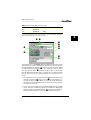
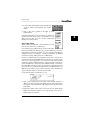
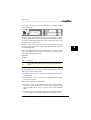
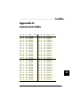
1
E
Universal Module
Version 2.0.2 – State: August 4, 1997
Adaptation Programming Manual
Also applicable for SoundSurfer
Universal MIDI Librarian Management
and Editor System
Windows 95 and NT 4.0
Mac OS
Atari ST, STE, TT and Falcon
TM
–
Distributor
E
Emagic Soft- und Hardware GmbH
Halstenbeker Weg 96
D-25462 Rellingen
Germany
http://www.emagic.de
All trademarks are property of their individual owners. »SoundSurfer« and
»SoundDiver« are registered trademarks of EMAGIC Soft- und Hardware
GmbH.
Credits
The contributors to the Universal Module and its programming manual
are:
Concept,
programming,
manual, layout, and
editing
Coordination
Beta-testing and
suggestions
Support gratefully
acknowledged
2
Michael Haydn
Andreas Dedring
Luca Anzilotti, Dietmar Belloff, MaBu, AJ Command,
Michael Cretu, Andreas Heggendorn, Kurt Hofmann,
Ueli Karlen, Dirk Karsten, Thomas Kern, Thomas Kerschbaum, Pit Löw, Gerhard Mannal, Siggi Müller,
Heinz Naleppa, Malte Rogacki, Christian Roth, Marc
Schlaile, Wolfgang Schmid, Kristian Schultze, Thomas
Siebert, and many others
CML, Dynacord, E-mu Systems, Ensoniq, Kawai,
Klemm, Korg, MIDITEMP, music shop, Musik Meyer,
Roland Deutschland, Kristian Schultze, Soundware
Audio Team, Waldorf, Yamaha Europa
E
Contents
Contents
Chapter 1
Introduction . . . . . . . . . . . . . . . . . . . . . . . . . . . . . . . . . . . . . . . . 17
About this manual . . . . . . . . . . . . . . . . . . . . . . . . . . . . . . . . . . . . . . 17
Conventions . . . . . . . . . . . . . . . . . . . . . . . . . . . . . . . . . . . . . . . . . . . 18
Terms . . . . . . . . . . . . . . . . . . . . . . . . . . . . . . . . . . . . . . . . . . . . 18
Keyboard shortcuts . . . . . . . . . . . . . . . . . . . . . . . . . . . . . . . . . 18
The SoundDiverBox BBS . . . . . . . . . . . . . . . . . . . . . . . . . . . . . . . . . 18
How to contact the SoundDiver programmers and Adaptation
authors . . . . . . . . . . . . . . . . . . . . . . . . . . . . . . . . . . . . . . . . . . . . . . . 19
Want to have your Adaptation included with SoundDiver? . . . . . 19
Want to become a SoundDiver programmer? . . . . . . . . . . . . . . . 20
Chapter 2
. . . . . . . . . . . . . . . . . . . . . . . . . . . . . . . . . . . . . . . . . . 23
Basics
Computer technology basics . . . . . . . . . . . . . . . . . . . . . . . . . . . . . 23
Numbering systems and their display . . . . . . . . . . . . . . . . . . 23
Hexadecimal display . . . . . . . . . . . . . . . . . . . . . . . . . . . . . 23
Binary display . . . . . . . . . . . . . . . . . . . . . . . . . . . . . . . . . . . 24
Octal display . . . . . . . . . . . . . . . . . . . . . . . . . . . . . . . . . . . . 25
Bits, Bytes, Words, and Longs . . . . . . . . . . . . . . . . . . . . . . . . . 25
ASCII . . . . . . . . . . . . . . . . . . . . . . . . . . . . . . . . . . . . . . . . . . . . . 25
SysEx messages . . . . . . . . . . . . . . . . . . . . . . . . . . . . . . . . . . . . . . . . 26
Global structure, manufacturer ID . . . . . . . . . . . . . . . . . . . . . 26
Model ID, device ID . . . . . . . . . . . . . . . . . . . . . . . . . . . . . . . . . 27
Command ID . . . . . . . . . . . . . . . . . . . . . . . . . . . . . . . . . . . . . . 28
SysEx limitations . . . . . . . . . . . . . . . . . . . . . . . . . . . . . . . . . . . 28
Using SysEx . . . . . . . . . . . . . . . . . . . . . . . . . . . . . . . . . . . . . . . . . . . 29
Structure of a device . . . . . . . . . . . . . . . . . . . . . . . . . . . . . . . . 29
SysEx message types . . . . . . . . . . . . . . . . . . . . . . . . . . . . . . . . 29
Transmission formats . . . . . . . . . . . . . . . . . . . . . . . . . . . . . . . 30
7 Bit . . . . . . . . . . . . . . . . . . . . . . . . . . . . . . . . . . . . . . . . . . . 30
Nibbles . . . . . . . . . . . . . . . . . . . . . . . . . . . . . . . . . . . . . . . . 30
ASCII Hex . . . . . . . . . . . . . . . . . . . . . . . . . . . . . . . . . . . . . . 31
8x7 Bit packed . . . . . . . . . . . . . . . . . . . . . . . . . . . . . . . . . . 31
Alesis Quadraverb . . . . . . . . . . . . . . . . . . . . . . . . . . . . . . . 31
User manual V2.0
3
7+1 Bit and 1+7 Bit . . . . . . . . . . . . . . . . . . . . . . . . . . . . . . 31
7 Bit and 1+7 Bit mixed . . . . . . . . . . . . . . . . . . . . . . . . . . . 32
Devices with word-oriented organization . . . . . . . . . . . . 32
2 times 7 Bit . . . . . . . . . . . . . . . . . . . . . . . . . . . . . . . . . . . . 32
Sample Dump Standard . . . . . . . . . . . . . . . . . . . . . . . . . . 32
Checksum formats . . . . . . . . . . . . . . . . . . . . . . . . . . . . . . . . . . 33
Roland SysEx . . . . . . . . . . . . . . . . . . . . . . . . . . . . . . . . . . . . . . 34
Handshake protocols . . . . . . . . . . . . . . . . . . . . . . . . . . . . . . . . 35
Parameters . . . . . . . . . . . . . . . . . . . . . . . . . . . . . . . . . . . . . . . . . . . . 36
Dumps and parameters . . . . . . . . . . . . . . . . . . . . . . . . . . . . . . 36
Transmission formats and parameter access . . . . . . . . . . . . 37
»big endian« vs. »little endian« . . . . . . . . . . . . . . . . . . . . . . . . 37
Encoding of negative numbers . . . . . . . . . . . . . . . . . . . . . . . . 38
Encoding of text . . . . . . . . . . . . . . . . . . . . . . . . . . . . . . . . . . . . 39
Parameter Change messages . . . . . . . . . . . . . . . . . . . . . . . . . 39
SysEx implementations - Poetry and Truth . . . . . . . . . . . . . . . . . . 40
Chapter 3
Tutorials . . . . . . . . . . . . . . . . . . . . . . . . . . . . . . . . . . . . . . . . . 43
Bank manager Kawai K1 . . . . . . . . . . . . . . . . . . . . . . . . . . . . . . . . . 43
Creating a new Adaptation . . . . . . . . . . . . . . . . . . . . . . . . . . . 44
Global parameters . . . . . . . . . . . . . . . . . . . . . . . . . . . . . . . . . . 44
Initialization message . . . . . . . . . . . . . . . . . . . . . . . . . . . . . . . 46
Defining the Scan function . . . . . . . . . . . . . . . . . . . . . . . . . . . 46
Defining the data types . . . . . . . . . . . . . . . . . . . . . . . . . . . . . . 47
Defining the bank drivers . . . . . . . . . . . . . . . . . . . . . . . . . . . . 48
Single Dump . . . . . . . . . . . . . . . . . . . . . . . . . . . . . . . . . . . 49
Single Request . . . . . . . . . . . . . . . . . . . . . . . . . . . . . . . . . . 51
Bank Dump . . . . . . . . . . . . . . . . . . . . . . . . . . . . . . . . . . . . 52
Bank Request . . . . . . . . . . . . . . . . . . . . . . . . . . . . . . . . . . . 53
Further Single banks . . . . . . . . . . . . . . . . . . . . . . . . . . . . . 54
Cartridge banks . . . . . . . . . . . . . . . . . . . . . . . . . . . . . . . . . 54
Edit buffer . . . . . . . . . . . . . . . . . . . . . . . . . . . . . . . . . . . . . 55
Multi banks . . . . . . . . . . . . . . . . . . . . . . . . . . . . . . . . . . . . . 56
Multi edit buffer . . . . . . . . . . . . . . . . . . . . . . . . . . . . . . . . . 57
Bank manager Roland D-110 . . . . . . . . . . . . . . . . . . . . . . . . . . . . . . 57
Creating a new Adaptation . . . . . . . . . . . . . . . . . . . . . . . . . . . 58
Global parameters . . . . . . . . . . . . . . . . . . . . . . . . . . . . . . . . . . 58
Defining the Scan function . . . . . . . . . . . . . . . . . . . . . . . . . . . 59
Defining the data type . . . . . . . . . . . . . . . . . . . . . . . . . . . . . . 60
Defining the bank driver (Tone Temporary) . . . . . . . . . . . . . 60
Defining the bank driver (Internal Tones) . . . . . . . . . . . . . . . 62
4
E
Defining a Conversion table . . . . . . . . . . . . . . . . . . . . . . . . . . 63
Generic mixer . . . . . . . . . . . . . . . . . . . . . . . . . . . . . . . . . . . . . . . . . 64
Designing the MIDI mixer . . . . . . . . . . . . . . . . . . . . . . . . . . . . 65
Creating a new Adaptation . . . . . . . . . . . . . . . . . . . . . . . . . . . 65
Making adjustments in the Adaptation editor . . . . . . . . . . . . 65
Global data . . . . . . . . . . . . . . . . . . . . . . . . . . . . . . . . . . . . . 66
»Data Type« block . . . . . . . . . . . . . . . . . . . . . . . . . . . . . . . 67
»Bank Driver« block . . . . . . . . . . . . . . . . . . . . . . . . . . . . . . 68
Creating the controls . . . . . . . . . . . . . . . . . . . . . . . . . . . . . . . . 69
Sliders . . . . . . . . . . . . . . . . . . . . . . . . . . . . . . . . . . . . . . . . . 69
Assigning a MIDI message . . . . . . . . . . . . . . . . . . . . . . . . 70
Input with a MIDI keyboard . . . . . . . . . . . . . . . . . . . . . . . . . .70
Manual input . . . . . . . . . . . . . . . . . . . . . . . . . . . . . . . . . . . . . .71
Switches . . . . . . . . . . . . . . . . . . . . . . . . . . . . . . . . . . . . . . . 71
Rotary knobs . . . . . . . . . . . . . . . . . . . . . . . . . . . . . . . . . . . 73
Copying objects (»Copy and Paste«) . . . . . . . . . . . . . . . . 74
Graphical appearance . . . . . . . . . . . . . . . . . . . . . . . . . . . . 76
Saving the Adaptation . . . . . . . . . . . . . . . . . . . . . . . . . . . . . . . 77
DX7 bank loader . . . . . . . . . . . . . . . . . . . . . . . . . . . . . . . . . . . . . . . 77
Installing a new Adaptation . . . . . . . . . . . . . . . . . . . . . . . . . . 78
Global settings in the Adaptation editor . . . . . . . . . . . . . . . . 78
Defining the data type for the Edit Voice . . . . . . . . . . . . . . . . 79
The Bank Driver for Edit Voice . . . . . . . . . . . . . . . . . . . . . . . . 80
The Dump string for Edit Voice . . . . . . . . . . . . . . . . . . . . 81
The Request string for Edit Voice . . . . . . . . . . . . . . . . . . . 83
Defining a 32-Voice Bank . . . . . . . . . . . . . . . . . . . . . . . . . . . . 84
The MIDI Strings for Internal Voices . . . . . . . . . . . . . . . . . 85
DX7 editor . . . . . . . . . . . . . . . . . . . . . . . . . . . . . . . . . . . . . . . . . . . . 86
Basic requirements . . . . . . . . . . . . . . . . . . . . . . . . . . . . . . . . . 86
Numerical Value Objects . . . . . . . . . . . . . . . . . . . . . . . . . . . . . 87
Envelopes . . . . . . . . . . . . . . . . . . . . . . . . . . . . . . . . . . . . . . . . . 89
Global settings for envelopes . . . . . . . . . . . . . . . . . . . . . . 90
Defining the envelope points . . . . . . . . . . . . . . . . . . . . . . 91
Chapter 4
Reference – Memory Managers . . . . . . . . . . . . . . . . . . . . 95
Structure of an Adaptation . . . . . . . . . . . . . . . . . . . . . . . . . . . . . . . 95
MIDI strings and pseudo bytes . . . . . . . . . . . . . . . . . . . . . . . . . . . . 95
Status bytes . . . . . . . . . . . . . . . . . . . . . . . . . . . . . . . . . . . . . . . 95
Data bytes . . . . . . . . . . . . . . . . . . . . . . . . . . . . . . . . . . . . . . . . 96
Pseudo bytes . . . . . . . . . . . . . . . . . . . . . . . . . . . . . . . . . . . . . . 96
VAL – Parameter value . . . . . . . . . . . . . . . . . . . . . . . . . . . 96
User manual V2.0
5
MEM – Memory occupied by parameter . . . . . . . . . . . . . 97
SIN – Single dump data . . . . . . . . . . . . . . . . . . . . . . . . . . 97
BNK – Bank dump data . . . . . . . . . . . . . . . . . . . . . . . . . . . 97
EN# – entry number in a bank . . . . . . . . . . . . . . . . . . . . . 98
CHK – Checksum . . . . . . . . . . . . . . . . . . . . . . . . . . . . . . . . 98
SUM – Sum up from here . . . . . . . . . . . . . . . . . . . . . . . . . 99
PAU – Pause . . . . . . . . . . . . . . . . . . . . . . . . . . . . . . . . . . . 99
[ – Loop start, ] – Loop end . . . . . . . . . . . . . . . . . . . . . 100
TRA – data size (transmitted bytes) . . . . . . . . . . . . . . . 101
STO – data size (stored bytes) . . . . . . . . . . . . . . . . . . . . 101
FRA – Fractional dump data . . . . . . . . . . . . . . . . . . . . . 102
SKI – Skip dump data . . . . . . . . . . . . . . . . . . . . . . . . . . 102
RES – Reset dump data pointer . . . . . . . . . . . . . . . . . . 102
Creating a new Adaptation . . . . . . . . . . . . . . . . . . . . . . . . . . . . . . 103
Adaptation editor . . . . . . . . . . . . . . . . . . . . . . . . . . . . . . . . . . . . . . 103
Window title . . . . . . . . . . . . . . . . . . . . . . . . . . . . . . . . . . . . . . 103
Fade in/out gadget . . . . . . . . . . . . . . . . . . . . . . . . . . . . . . . . 103
The cursor . . . . . . . . . . . . . . . . . . . . . . . . . . . . . . . . . . . . . . . . 104
Selection and insertion point . . . . . . . . . . . . . . . . . . . . . . . . 104
Selecting a definition block . . . . . . . . . . . . . . . . . . . . . . 105
Setting the insertion point . . . . . . . . . . . . . . . . . . . . . . . 105
Global Edit menu . . . . . . . . . . . . . . . . . . . . . . . . . . . . . . . . . . 106
Undo . . . . . . . . . . . . . . . . . . . . . . . . . . . . . . . . . . . . . . . . . 106
Redo . . . . . . . . . . . . . . . . . . . . . . . . . . . . . . . . . . . . . . . . . 106
Cut . . . . . . . . . . . . . . . . . . . . . . . . . . . . . . . . . . . . . . . . . . 106
Copy . . . . . . . . . . . . . . . . . . . . . . . . . . . . . . . . . . . . . . . . . 106
Paste . . . . . . . . . . . . . . . . . . . . . . . . . . . . . . . . . . . . . . . . . 106
Clear . . . . . . . . . . . . . . . . . . . . . . . . . . . . . . . . . . . . . . . . . 106
Select All . . . . . . . . . . . . . . . . . . . . . . . . . . . . . . . . . . . . . . 107
Local menu . . . . . . . . . . . . . . . . . . . . . . . . . . . . . . . . . . . . . . . 107
New data type . . . . . . . . . . . . . . . . . . . . . . . . . . . . . . . . . 107
New address mapping table . . . . . . . . . . . . . . . . . . . . . . 107
New bank driver . . . . . . . . . . . . . . . . . . . . . . . . . . . . . . . . 107
New conversion table . . . . . . . . . . . . . . . . . . . . . . . . . . . 108
Save . . . . . . . . . . . . . . . . . . . . . . . . . . . . . . . . . . . . . . . . . 108
Export names … . . . . . . . . . . . . . . . . . . . . . . . . . . . . . . . . 108
Info line . . . . . . . . . . . . . . . . . . . . . . . . . . . . . . . . . . . . . . . 109
Editing MIDI strings . . . . . . . . . . . . . . . . . . . . . . . . . . . . . . . . 109
Global parameters . . . . . . . . . . . . . . . . . . . . . . . . . . . . . . . . . . . . . 110
Manufacturer . . . . . . . . . . . . . . . . . . . . . . . . . . . . . . . . . . . . . 110
Model name . . . . . . . . . . . . . . . . . . . . . . . . . . . . . . . . . . . . . . 111
Device ID offset . . . . . . . . . . . . . . . . . . . . . . . . . . . . . . . . . . . 113
Device ID Min/Max . . . . . . . . . . . . . . . . . . . . . . . . . . . . . . . . . 113
6
E
Device ID +1 . . . . . . . . . . . . . . . . . . . . . . . . . . . . . . . . . . . . . . 113
Thru Channel = Device ID . . . . . . . . . . . . . . . . . . . . . . . . . . . 114
Icon . . . . . . . . . . . . . . . . . . . . . . . . . . . . . . . . . . . . . . . . . . . . . 114
Input status enable . . . . . . . . . . . . . . . . . . . . . . . . . . . . . . . . 114
Default Timeout, Default Send Pause, and
Default Play Delay . . . . . . . . . . . . . . . . . . . . . . . . . . . . . . 114
Roland SysEx . . . . . . . . . . . . . . . . . . . . . . . . . . . . . . . . . . . . . . 116
Roland Model . . . . . . . . . . . . . . . . . . . . . . . . . . . . . . . . . . . . . 116
Author . . . . . . . . . . . . . . . . . . . . . . . . . . . . . . . . . . . . . . . . . . . 117
Card names . . . . . . . . . . . . . . . . . . . . . . . . . . . . . . . . . . . . . . 117
Global MIDI Strings . . . . . . . . . . . . . . . . . . . . . . . . . . . . . . . . . . . . 117
Initialization . . . . . . . . . . . . . . . . . . . . . . . . . . . . . . . . . . . . . . 118
Failure Response . . . . . . . . . . . . . . . . . . . . . . . . . . . . . . . . . . 118
Device Scan . . . . . . . . . . . . . . . . . . . . . . . . . . . . . . . . . . . . . . . . . . 118
Universal SysEx Device Inquiry . . . . . . . . . . . . . . . . . . . . . . . 118
Request / Answer message pairs . . . . . . . . . . . . . . . . . . . . . 120
Use for Scan . . . . . . . . . . . . . . . . . . . . . . . . . . . . . . . . . . . . . . 120
Special cases . . . . . . . . . . . . . . . . . . . . . . . . . . . . . . . . . . . . . . 120
Mode of operation . . . . . . . . . . . . . . . . . . . . . . . . . . . . . . . . . 121
Data type . . . . . . . . . . . . . . . . . . . . . . . . . . . . . . . . . . . . . . . . . . . . 122
Type name . . . . . . . . . . . . . . . . . . . . . . . . . . . . . . . . . . . . . . . 122
Data size . . . . . . . . . . . . . . . . . . . . . . . . . . . . . . . . . . . . . . . . . 123
Entries with variable size . . . . . . . . . . . . . . . . . . . . . . . . . 123
Name size . . . . . . . . . . . . . . . . . . . . . . . . . . . . . . . . . . . . . . . . 125
Name offset . . . . . . . . . . . . . . . . . . . . . . . . . . . . . . . . . . . . . . 125
Name format . . . . . . . . . . . . . . . . . . . . . . . . . . . . . . . . . . . . . 125
Parameter Send Pause (SoundDiver only) . . . . . . . . . . . . . . 126
Init values . . . . . . . . . . . . . . . . . . . . . . . . . . . . . . . . . . . . . . . . 127
Name bytes contain data . . . . . . . . . . . . . . . . . . . . . . . . . . . 128
Address Mapping . . . . . . . . . . . . . . . . . . . . . . . . . . . . . . . . . . 128
Bank driver . . . . . . . . . . . . . . . . . . . . . . . . . . . . . . . . . . . . . . . . . . . 132
Common bank parameters . . . . . . . . . . . . . . . . . . . . . . . . . . 133
Bank name . . . . . . . . . . . . . . . . . . . . . . . . . . . . . . . . . . . . 133
Data type . . . . . . . . . . . . . . . . . . . . . . . . . . . . . . . . . . . . . 133
X . . . . . . . . . . . . . . . . . . . . . . . . . . . . . . . . . . . . . . . . . . . . 133
Y . . . . . . . . . . . . . . . . . . . . . . . . . . . . . . . . . . . . . . . . . . . . 134
# of entries . . . . . . . . . . . . . . . . . . . . . . . . . . . . . . . . . . . . 135
# of rows . . . . . . . . . . . . . . . . . . . . . . . . . . . . . . . . . . . . . . 135
Bank numbering . . . . . . . . . . . . . . . . . . . . . . . . . . . . . . . 136
H/V title . . . . . . . . . . . . . . . . . . . . . . . . . . . . . . . . . . . . . . 138
Transmission format . . . . . . . . . . . . . . . . . . . . . . . . . . . . 138
Card switches . . . . . . . . . . . . . . . . . . . . . . . . . . . . . . . . . . 142
Editable . . . . . . . . . . . . . . . . . . . . . . . . . . . . . . . . . . . . . . . 142
User manual V2.0
7
Memory location . . . . . . . . . . . . . . . . . . . . . . . . . . . . . . . 143
ROM location . . . . . . . . . . . . . . . . . . . . . . . . . . . . . . . . . . 144
Use for Scan . . . . . . . . . . . . . . . . . . . . . . . . . . . . . . . . . . . 144
Request regularly . . . . . . . . . . . . . . . . . . . . . . . . . . . . . . . 144
Default Names . . . . . . . . . . . . . . . . . . . . . . . . . . . . . . . . . 145
Program Change detection . . . . . . . . . . . . . . . . . . . . . . 146
CHAN – MIDI channel and master switch . . . . . . . . . . . . .
BANK-MSB . . . . . . . . . . . . . . . . . . . . . . . . . . . . . . . . . . . . . .
BANK-LSB . . . . . . . . . . . . . . . . . . . . . . . . . . . . . . . . . . . . . . .
FIXED . . . . . . . . . . . . . . . . . . . . . . . . . . . . . . . . . . . . . . . . . .
OFFSET . . . . . . . . . . . . . . . . . . . . . . . . . . . . . . . . . . . . . . . . .
147
148
148
148
149
Standard parameters . . . . . . . . . . . . . . . . . . . . . . . . . . . . . . . 149
Checksum type . . . . . . . . . . . . . . . . . . . . . . . . . . . . . . . . 149
EN# Offset . . . . . . . . . . . . . . . . . . . . . . . . . . . . . . . . . . . . 150
EN# Format . . . . . . . . . . . . . . . . . . . . . . . . . . . . . . . . . . . 150
Roland parameters . . . . . . . . . . . . . . . . . . . . . . . . . . . . . . . . 151
Packet Size . . . . . . . . . . . . . . . . . . . . . . . . . . . . . . . . . . . . 151
Mode . . . . . . . . . . . . . . . . . . . . . . . . . . . . . . . . . . . . . . . . 152
Address Base . . . . . . . . . . . . . . . . . . . . . . . . . . . . . . . . . . 152
Distance . . . . . . . . . . . . . . . . . . . . . . . . . . . . . . . . . . . . . . 153
No Request . . . . . . . . . . . . . . . . . . . . . . . . . . . . . . . . . . . . 153
Aligned . . . . . . . . . . . . . . . . . . . . . . . . . . . . . . . . . . . . . . . 154
Bank driver MIDI strings . . . . . . . . . . . . . . . . . . . . . . . . . . . . 154
Single Request . . . . . . . . . . . . . . . . . . . . . . . . . . . . . . . . . 154
Single Dump . . . . . . . . . . . . . . . . . . . . . . . . . . . . . . . . . . 154
Bank Request . . . . . . . . . . . . . . . . . . . . . . . . . . . . . . . . . . 155
Bank Dump . . . . . . . . . . . . . . . . . . . . . . . . . . . . . . . . . . . 155
Before Request/Dump . . . . . . . . . . . . . . . . . . . . . . . . . . . 155
After Dump . . . . . . . . . . . . . . . . . . . . . . . . . . . . . . . . . . . 156
Global advice on requests and dumps . . . . . . . . . . . . . . 158
Conversion tables . . . . . . . . . . . . . . . . . . . . . . . . . . . . . . . . . . . . . . 160
Structure of a Conversion table . . . . . . . . . . . . . . . . . . . . . . 160
Creating a new conversion table . . . . . . . . . . . . . . . . . . . . . 160
Conversion steps . . . . . . . . . . . . . . . . . . . . . . . . . . . . . . . . . . 161
Transfer . . . . . . . . . . . . . . . . . . . . . . . . . . . . . . . . . . . . . . 161
Initialize . . . . . . . . . . . . . . . . . . . . . . . . . . . . . . . . . . . . . . 162
Loop start . . . . . . . . . . . . . . . . . . . . . . . . . . . . . . . . . . . . . 162
Loop end . . . . . . . . . . . . . . . . . . . . . . . . . . . . . . . . . . . . . 163
Jump . . . . . . . . . . . . . . . . . . . . . . . . . . . . . . . . . . . . . . . . . 163
Notes on the mode of operation of conversions . . . . . . . . . 163
Examples . . . . . . . . . . . . . . . . . . . . . . . . . . . . . . . . . . . . . . . . 164
File conversion . . . . . . . . . . . . . . . . . . . . . . . . . . . . . . . . . . . . . . . . 165
Using SoundSurfer Adaptations with SoundDiver and vice
versa . . . . . . . . . . . . . . . . . . . . . . . . . . . . . . . . . . . . . . . . . 165
8
E
Converting Windows or Atari Adaptation files to Macintosh and
vice versa . . . . . . . . . . . . . . . . . . . . . . . . . . . . . . . . . . . . . 166
Windows/Atari to Macintosh . . . . . . . . . . . . . . . . . . . . . 166
Macintosh to Windows/Atari . . . . . . . . . . . . . . . . . . . . . 167
Atari to Windows . . . . . . . . . . . . . . . . . . . . . . . . . . . . . . . 167
Windows to Atari . . . . . . . . . . . . . . . . . . . . . . . . . . . . . . . 167
Converting Polyframe Adaptation files . . . . . . . . . . . . . . . . 168
Windows/Atari . . . . . . . . . . . . . . . . . . . . . . . . . . . . . . . . . 168
Mac . . . . . . . . . . . . . . . . . . . . . . . . . . . . . . . . . . . . . . . . . . 169
Help files . . . . . . . . . . . . . . . . . . . . . . . . . . . . . . . . . . . . . . . . . 169
Polyframe help files . . . . . . . . . . . . . . . . . . . . . . . . . . . . . 169
Atari to Macintosh . . . . . . . . . . . . . . . . . . . . . . . . . . . . . . 170
Chapter 5
Reference – Editors . . . . . . . . . . . . . . . . . . . . . . . . . . . . . . . . 171
The concept . . . . . . . . . . . . . . . . . . . . . . . . . . . . . . . . . . . . . . . . . . 171
Creating a new Editor . . . . . . . . . . . . . . . . . . . . . . . . . . . . . . . . . . 172
Object operations . . . . . . . . . . . . . . . . . . . . . . . . . . . . . . . . . . . . . 172
Creating new objects . . . . . . . . . . . . . . . . . . . . . . . . . . . . . . . 173
Selecting objects . . . . . . . . . . . . . . . . . . . . . . . . . . . . . . . . . . 174
Selecting a single object (deselecting all other objects) . .
174
Selecting additional objects . . . . . . . . . . . . . . . . . . . . . . 174
Deselecting a single object . . . . . . . . . . . . . . . . . . . . . . . 174
Selecting objects with the »rubber-band« . . . . . . . . . . . 174
Deselecting all objects . . . . . . . . . . . . . . . . . . . . . . . . . . 175
Moving objects . . . . . . . . . . . . . . . . . . . . . . . . . . . . . . . . . . . . 175
Changing the size of objects . . . . . . . . . . . . . . . . . . . . . . . . . 175
Copying objects . . . . . . . . . . . . . . . . . . . . . . . . . . . . . . . . . . . 176
Opening the object editor window . . . . . . . . . . . . . . . . . . . 176
»Edit« menu functions . . . . . . . . . . . . . . . . . . . . . . . . . . . . . . . . . . 176
Undo . . . . . . . . . . . . . . . . . . . . . . . . . . . . . . . . . . . . . . . . . . . . 177
Redo . . . . . . . . . . . . . . . . . . . . . . . . . . . . . . . . . . . . . . . . . . . . 177
Cut . . . . . . . . . . . . . . . . . . . . . . . . . . . . . . . . . . . . . . . . . . . . . 177
Copy . . . . . . . . . . . . . . . . . . . . . . . . . . . . . . . . . . . . . . . . . . . . 177
Paste . . . . . . . . . . . . . . . . . . . . . . . . . . . . . . . . . . . . . . . . . . . . 178
Clear . . . . . . . . . . . . . . . . . . . . . . . . . . . . . . . . . . . . . . . . . . . . 178
Select All . . . . . . . . . . . . . . . . . . . . . . . . . . . . . . . . . . . . . . . . . 178
Toggle selection . . . . . . . . . . . . . . . . . . . . . . . . . . . . . . . . . . . 178
»Adaptation« menu functions . . . . . . . . . . . . . . . . . . . . . . . . . . . . 179
Binary View . . . . . . . . . . . . . . . . . . . . . . . . . . . . . . . . . . . . . . . 179
Layout Mode . . . . . . . . . . . . . . . . . . . . . . . . . . . . . . . . . . . . . 180
User manual V2.0
9
Grid Snap . . . . . . . . . . . . . . . . . . . . . . . . . . . . . . . . . . . . . . . . 180
Object Snap . . . . . . . . . . . . . . . . . . . . . . . . . . . . . . . . . . . . . . 180
»New object« submenu . . . . . . . . . . . . . . . . . . . . . . . . . . . . . 181
Open Object Editor . . . . . . . . . . . . . . . . . . . . . . . . . . . . . . . . 181
Snap to Grid . . . . . . . . . . . . . . . . . . . . . . . . . . . . . . . . . . . . . . 181
Flatten . . . . . . . . . . . . . . . . . . . . . . . . . . . . . . . . . . . . . . . . . . . 181
Edit Adaptation . . . . . . . . . . . . . . . . . . . . . . . . . . . . . . . . . . . 181
Save Adaptation . . . . . . . . . . . . . . . . . . . . . . . . . . . . . . . . . . . 182
Object editors . . . . . . . . . . . . . . . . . . . . . . . . . . . . . . . . . . . . . . . . . 182
Editing several objects simultaneously . . . . . . . . . . . . . . . . 182
Parameters common to several object types . . . . . . . . . . . 183
Border (switch) . . . . . . . . . . . . . . . . . . . . . . . . . . . . . . . . 183
Fill (switch) . . . . . . . . . . . . . . . . . . . . . . . . . . . . . . . . . . . . 183
Border (flip menu) . . . . . . . . . . . . . . . . . . . . . . . . . . . . . . 183
Fill (flip menu) . . . . . . . . . . . . . . . . . . . . . . . . . . . . . . . . . 184
Color (flip menu) . . . . . . . . . . . . . . . . . . . . . . . . . . . . . . . 184
Large/Medium/Small . . . . . . . . . . . . . . . . . . . . . . . . . . . . 184
Flip Menu (switch) . . . . . . . . . . . . . . . . . . . . . . . . . . . . . . 185
Shadow . . . . . . . . . . . . . . . . . . . . . . . . . . . . . . . . . . . . . . . 185
Inverted (display) . . . . . . . . . . . . . . . . . . . . . . . . . . . . . . . 185
Minimum/Maximum . . . . . . . . . . . . . . . . . . . . . . . . . . . . 185
X, Y, W, H . . . . . . . . . . . . . . . . . . . . . . . . . . . . . . . . . . . . . 186
Format . . . . . . . . . . . . . . . . . . . . . . . . . . . . . . . . . . . . . . . 186
0 Offset . . . . . . . . . . . . . . . . . . . . . . . . . . . . . . . . . . . . . . . 188
Bit field definition . . . . . . . . . . . . . . . . . . . . . . . . . . . . . . 188
LS Bit / # of bits . . . . . . . . . . . . . . . . . . . . . . . . . . . . . . . . . .
Expanded bit field definition . . . . . . . . . . . . . . . . . . . . . . . .
# of skipped Bits . . . . . . . . . . . . . . . . . . . . . . . . . . . . . . . . .
Skipped LS Bit . . . . . . . . . . . . . . . . . . . . . . . . . . . . . . . . . . .
2’s complement / Sign magnitude . . . . . . . . . . . . . . . . . .
Order . . . . . . . . . . . . . . . . . . . . . . . . . . . . . . . . . . . . . . . . . .
188
189
189
189
190
191
Mem.Offset . . . . . . . . . . . . . . . . . . . . . . . . . . . . . . . . . . . 191
Message . . . . . . . . . . . . . . . . . . . . . . . . . . . . . . . . . . . . . . 191
Name . . . . . . . . . . . . . . . . . . . . . . . . . . . . . . . . . . . . . . . . 192
Transmission Format . . . . . . . . . . . . . . . . . . . . . . . . . . . . 192
...............................................
Transmission formats »Controller« . . . . . . . . . . . . . . . . . . .
Transmission formats »Controller, integer steps« . . . . . . .
Transmission formats »ASCII Hex HL« and »ASCII Hex LH«
Transmission format »ASCII Decimal« . . . . . . . . . . . . . . . .
Transmission format »ASCII Dec., 0-terminated« . . . . . . .
Transmission formats »1+7 Bit HL« and »7+1 Bit LH« . . . .
193
194
194
195
195
196
196
Inverted (transmission format) . . . . . . . . . . . . . . . . . . . . 197
Text/Box . . . . . . . . . . . . . . . . . . . . . . . . . . . . . . . . . . . . . . . . . 197
Inverse . . . . . . . . . . . . . . . . . . . . . . . . . . . . . . . . . . . . . . . 197
10
E
centered/leftalign/rightalign . . . . . . . . . . . . . . . . . . . . . 197
Text . . . . . . . . . . . . . . . . . . . . . . . . . . . . . . . . . . . . . . . . . . 198
Image objects . . . . . . . . . . . . . . . . . . . . . . . . . . . . . . . . . . . . . 198
User . . . . . . . . . . . . . . . . . . . . . . . . . . . . . . . . . . . . . . . . . . 198
Zoom . . . . . . . . . . . . . . . . . . . . . . . . . . . . . . . . . . . . . . . . 198
Grid . . . . . . . . . . . . . . . . . . . . . . . . . . . . . . . . . . . . . . . . . . 199
Functions . . . . . . . . . . . . . . . . . . . . . . . . . . . . . . . . . . . . . 199
All White . . . . . . . . . . . . . . . . . . . . . . . . . . . . . . . . . . . . . . . . 199
All Black . . . . . . . . . . . . . . . . . . . . . . . . . . . . . . . . . . . . . . . . 199
Shift Left/Right/Up/Down . . . . . . . . . . . . . . . . . . . . . . . . . . 199
X, Y, W, H . . . . . . . . . . . . . . . . . . . . . . . . . . . . . . . . . . . . . 199
Arrow . . . . . . . . . . . . . . . . . . . . . . . . . . . . . . . . . . . . . . . . . . . 199
Direction . . . . . . . . . . . . . . . . . . . . . . . . . . . . . . . . . . . . . . 199
Thickness . . . . . . . . . . . . . . . . . . . . . . . . . . . . . . . . . . . . . 200
Numerical values . . . . . . . . . . . . . . . . . . . . . . . . . . . . . . . . . . 200
Format . . . . . . . . . . . . . . . . . . . . . . . . . . . . . . . . . . . . . . . 200
Text values . . . . . . . . . . . . . . . . . . . . . . . . . . . . . . . . . . . . . . . 201
Minimum/Maximum . . . . . . . . . . . . . . . . . . . . . . . . . . . . 201
Text Length . . . . . . . . . . . . . . . . . . . . . . . . . . . . . . . . . . . 201
Text input field . . . . . . . . . . . . . . . . . . . . . . . . . . . . . . . . . 201
Fill menu . . . . . . . . . . . . . . . . . . . . . . . . . . . . . . . . . . . . . . 202
Sliders . . . . . . . . . . . . . . . . . . . . . . . . . . . . . . . . . . . . . . . . . . . 202
Handling . . . . . . . . . . . . . . . . . . . . . . . . . . . . . . . . . . . . . . 202
Format . . . . . . . . . . . . . . . . . . . . . . . . . . . . . . . . . . . . . . . 202
Type . . . . . . . . . . . . . . . . . . . . . . . . . . . . . . . . . . . . . . . . . 202
Rotary knobs . . . . . . . . . . . . . . . . . . . . . . . . . . . . . . . . . . . . . 203
Type . . . . . . . . . . . . . . . . . . . . . . . . . . . . . . . . . . . . . . . . . 203
Switches . . . . . . . . . . . . . . . . . . . . . . . . . . . . . . . . . . . . . . . . . 203
Style . . . . . . . . . . . . . . . . . . . . . . . . . . . . . . . . . . . . . . . . . 204
Send immediately . . . . . . . . . . . . . . . . . . . . . . . . . . . . . . 204
Text . . . . . . . . . . . . . . . . . . . . . . . . . . . . . . . . . . . . . . . . . . 204
Function . . . . . . . . . . . . . . . . . . . . . . . . . . . . . . . . . . . . . . 204
Using switches to jump to screensets . . . . . . . . . . . . . . 204
Envelopes . . . . . . . . . . . . . . . . . . . . . . . . . . . . . . . . . . . . . . . . 205
Global parameters . . . . . . . . . . . . . . . . . . . . . . . . . . . . . . 206
Range . . . . . . . . . . . . . . . . . . . . . . . . . . . . . . . . . . . . . . . . . . 206
Help Lines . . . . . . . . . . . . . . . . . . . . . . . . . . . . . . . . . . . . . . . 206
Envelope points . . . . . . . . . . . . . . . . . . . . . . . . . . . . . . . . 206
Selection column . . . . . . . . . . . . . . . . . . . . . . . . . . . . . . . . .
Help Lines . . . . . . . . . . . . . . . . . . . . . . . . . . . . . . . . . . . . . . .
Object Link . . . . . . . . . . . . . . . . . . . . . . . . . . . . . . . . . . . . . .
Reciprocal . . . . . . . . . . . . . . . . . . . . . . . . . . . . . . . . . . . . . . .
OP (Operator) and Const . . . . . . . . . . . . . . . . . . . . . . . . . .
Positioning . . . . . . . . . . . . . . . . . . . . . . . . . . . . . . . . . . . . . .
User manual V2.0
206
206
206
207
207
208
11
Keyboard and Key/Velocity windows . . . . . . . . . . . . . . . . . . 208
Global parameters . . . . . . . . . . . . . . . . . . . . . . . . . . . . . . 209
Mode . . . . . . . . . . . . . . . . . . . . . . . . . . . . . . . . . . . . . . . . . .
Keyb H . . . . . . . . . . . . . . . . . . . . . . . . . . . . . . . . . . . . . . . . .
Range . . . . . . . . . . . . . . . . . . . . . . . . . . . . . . . . . . . . . . . . . .
Direction . . . . . . . . . . . . . . . . . . . . . . . . . . . . . . . . . . . . . . .
Labels . . . . . . . . . . . . . . . . . . . . . . . . . . . . . . . . . . . . . . . . . .
Keyboard . . . . . . . . . . . . . . . . . . . . . . . . . . . . . . . . . . . . . . .
Value limitation . . . . . . . . . . . . . . . . . . . . . . . . . . . . . . . . . .
209
209
210
210
210
210
210
Keyboard range, Velocity range . . . . . . . . . . . . . . . . . . . 211
Object Link . . . . . . . . . . . . . . . . . . . . . . . . . . . . . . . . . . . . . .
Reciprocal . . . . . . . . . . . . . . . . . . . . . . . . . . . . . . . . . . . . . .
OP (Operator) and Const . . . . . . . . . . . . . . . . . . . . . . . . . .
Positioning . . . . . . . . . . . . . . . . . . . . . . . . . . . . . . . . . . . . . .
211
211
211
211
Parameter Changes . . . . . . . . . . . . . . . . . . . . . . . . . . . . . . . . . . . . 212
Principle . . . . . . . . . . . . . . . . . . . . . . . . . . . . . . . . . . . . . . . . . 212
Pseudo bytes . . . . . . . . . . . . . . . . . . . . . . . . . . . . . . . . . . . . . 212
VAL – Parameter value, MEM – memory used for
Parameter . . . . . . . . . . . . . . . . . . . . . . . . . . . . . . . . . . . . . 212
EN# – Entry number in bank . . . . . . . . . . . . . . . . . . . . . . 213
SUM – Sum up from here . . . . . . . . . . . . . . . . . . . . . . . . . 213
CHK – Checksum . . . . . . . . . . . . . . . . . . . . . . . . . . . . . . . 214
PAU – Pause . . . . . . . . . . . . . . . . . . . . . . . . . . . . . . . . . . . 214
[ and ] – »Repeat« feature . . . . . . . . . . . . . . . . . . . . . . . 214
Transmission details . . . . . . . . . . . . . . . . . . . . . . . . . . . . . . . 214
Roland mode specific notes . . . . . . . . . . . . . . . . . . . . . . . . . 215
Automatic analysis of MIDI messages (Analyze) . . . . . . . . . 216
How Analyze works . . . . . . . . . . . . . . . . . . . . . . . . . . . . . 216
How to create good editors . . . . . . . . . . . . . . . . . . . . . . . . . . . . . 217
Chapter 6
The SSHC help compiler . . . . . . . . . . . . . . . . . . . . . . . . . . . 219
Requirements . . . . . . . . . . . . . . . . . . . . . . . . . . . . . . . . . . . . . . . . . 219
Command shell . . . . . . . . . . . . . . . . . . . . . . . . . . . . . . . . . . . 219
Text editor . . . . . . . . . . . . . . . . . . . . . . . . . . . . . . . . . . . . . . . 219
Additional tools . . . . . . . . . . . . . . . . . . . . . . . . . . . . . . . . . . . 220
Installing SSHC . . . . . . . . . . . . . . . . . . . . . . . . . . . . . . . . . . . . . . . . 220
Windows 95 . . . . . . . . . . . . . . . . . . . . . . . . . . . . . . . . . . . . . . 220
Macintosh . . . . . . . . . . . . . . . . . . . . . . . . . . . . . . . . . . . . . . . . 221
Atari . . . . . . . . . . . . . . . . . . . . . . . . . . . . . . . . . . . . . . . . . . . . 221
Tutorials . . . . . . . . . . . . . . . . . . . . . . . . . . . . . . . . . . . . . . . . . . . . . 221
Creating an SSHC help source file . . . . . . . . . . . . . . . . . . . . 221
Starting SSHC directly . . . . . . . . . . . . . . . . . . . . . . . . . . . . . . 222
12
E
Starting SSHC from a command shell . . . . . . . . . . . . . . . . . 222
Format of source files . . . . . . . . . . . . . . . . . . . . . . . . . . . . . . . . . . 223
Platform indicator . . . . . . . . . . . . . . . . . . . . . . . . . . . . . . . . . 224
Control characters . . . . . . . . . . . . . . . . . . . . . . . . . . . . . . . . . 225
\f (Form Feed) . . . . . . . . . . . . . . . . . . . . . . . . . . . . . . . . 225
\n (Newline) . . . . . . . . . . . . . . . . . . . . . . . . . . . . . . . . . . 226
\r (Carriage Return) . . . . . . . . . . . . . . . . . . . . . . . . . . . . 227
\! (Exclamation Icon) . . . . . . . . . . . . . . . . . . . . . . . . . . . 227
\e (eg Icon) . . . . . . . . . . . . . . . . . . . . . . . . . . . . . . . . . . . 228
\i (Info Icon) . . . . . . . . . . . . . . . . . . . . . . . . . . . . . . . . . . 228
\m (Mouse Icon) . . . . . . . . . . . . . . . . . . . . . . . . . . . . . . . . 228
How to use icons correctly . . . . . . . . . . . . . . . . . . . . . . . 228
\p (Product name) . . . . . . . . . . . . . . . . . . . . . . . . . . . . . 228
\l (Listen to MIDI Icon) . . . . . . . . . . . . . . . . . . . . . . . . . 229
\w (Word Wrap) . . . . . . . . . . . . . . . . . . . . . . . . . . . . . . . . 229
\ (Backslash, Space) . . . . . . . . . . . . . . . . . . . . . . . . . . . . 229
\\ (Backslash, Backslash) . . . . . . . . . . . . . . . . . . . . . . . . 230
\/ (Backslash, Slash) . . . . . . . . . . . . . . . . . . . . . . . . . . . . 230
\( and \) (conditional compiling) . . . . . . . . . . . . . . . . . 231
Example for correct usage . . . . . . . . . . . . . . . . . . . . . . . . . . . 232
Enumerations . . . . . . . . . . . . . . . . . . . . . . . . . . . . . . . . . . 232
Tables . . . . . . . . . . . . . . . . . . . . . . . . . . . . . . . . . . . . . . . . 232
Icons . . . . . . . . . . . . . . . . . . . . . . . . . . . . . . . . . . . . . . . . . 232
Conventions for help files . . . . . . . . . . . . . . . . . . . . . . . . . . . . . . . 233
Standard keywords used by SoundDiver/SoundSurfer . . . . 234
<model name> . . . . . . . . . . . . . . . . . . . . . . . . . . . . . . . . . 234
»Installation« . . . . . . . . . . . . . . . . . . . . . . . . . . . . . . . . . . 234
»Scan« . . . . . . . . . . . . . . . . . . . . . . . . . . . . . . . . . . . . . . . . 234
»MIDI« . . . . . . . . . . . . . . . . . . . . . . . . . . . . . . . . . . . . . . . . 235
»SysEx Communication Error« . . . . . . . . . . . . . . . . . . . . 235
»Memory Manager« . . . . . . . . . . . . . . . . . . . . . . . . . . . . . 235
<data type> . . . . . . . . . . . . . . . . . . . . . . . . . . . . . . . . . . . 235
<bank name> . . . . . . . . . . . . . . . . . . . . . . . . . . . . . . . . . . 235
»Device Parameter box« . . . . . . . . . . . . . . . . . . . . . . . . . 236
<Data type> »Editor« . . . . . . . . . . . . . . . . . . . . . . . . . . . . 236
<parameter name> . . . . . . . . . . . . . . . . . . . . . . . . . . . . . 236
<parameter group name> . . . . . . . . . . . . . . . . . . . . . . . . 237
»Conversion« . . . . . . . . . . . . . . . . . . . . . . . . . . . . . . . . . . 237
»Credits« . . . . . . . . . . . . . . . . . . . . . . . . . . . . . . . . . . . . . . 237
»Copyright« . . . . . . . . . . . . . . . . . . . . . . . . . . . . . . . . . . . 238
Notes on how to write good help files . . . . . . . . . . . . . . . . . 238
Transcripting printed manuals . . . . . . . . . . . . . . . . . . . . 238
Listen to MIDI . . . . . . . . . . . . . . . . . . . . . . . . . . . . . . . . . . 238
User manual V2.0
13
Kopiermöglichkeiten . . . . . . . . . . . . . . . . . . . . . . . . . . . . 238
Cross-references . . . . . . . . . . . . . . . . . . . . . . . . . . . . . . . 239
Repeated characters . . . . . . . . . . . . . . . . . . . . . . . . . . . . 239
Indentions . . . . . . . . . . . . . . . . . . . . . . . . . . . . . . . . . . . . 239
Parameter descriptions . . . . . . . . . . . . . . . . . . . . . . . . . . 240
Running SSHC . . . . . . . . . . . . . . . . . . . . . . . . . . . . . . . . . . . . . . . . . 241
Windows . . . . . . . . . . . . . . . . . . . . . . . . . . . . . . . . . . . . . . . . . 241
Macintosh . . . . . . . . . . . . . . . . . . . . . . . . . . . . . . . . . . . . . . . . 241
Menu bar . . . . . . . . . . . . . . . . . . . . . . . . . . . . . . . . . . . . . 241
ð > About SSHC . . . . . . . . . . . . . . . . . . . . . . . . . . . . . . . . . .
ð > Help . . . . . . . . . . . . . . . . . . . . . . . . . . . . . . . . . . . . . . . .
File > Compile … . . . . . . . . . . . . . . . . . . . . . . . . . . . . . . . . .
File > Remove help … . . . . . . . . . . . . . . . . . . . . . . . . . . . . .
File > Preferences … . . . . . . . . . . . . . . . . . . . . . . . . . . . . . .
241
241
241
241
242
Options file . . . . . . . . . . . . . . . . . . . . . . . . . . . . . . . . . . . . 242
Apple Events . . . . . . . . . . . . . . . . . . . . . . . . . . . . . . . . . . 243
Atari . . . . . . . . . . . . . . . . . . . . . . . . . . . . . . . . . . . . . . . . . . . . 243
SSHC options . . . . . . . . . . . . . . . . . . . . . . . . . . . . . . . . . . . . . 243
-h (+help) . . . . . . . . . . . . . . . . . . . . . . . . . . . . . . . . . . 243
-v (+verbose) . . . . . . . . . . . . . . . . . . . . . . . . . . . . . . 243
-l (+light) . . . . . . . . . . . . . . . . . . . . . . . . . . . . . . . . . 244
-m (+make) . . . . . . . . . . . . . . . . . . . . . . . . . . . . . . . . . . 244
-n (+no_compression) . . . . . . . . . . . . . . . . . . . . . 244
-s (+standard) . . . . . . . . . . . . . . . . . . . . . . . . . . . . . 245
-r<offset> . . . . . . . . . . . . . . . . . . . . . . . . . . . . . . . . . . . . 245
-o<output file> . . . . . . . . . . . . . . . . . . . . . . . . . . . . . . . . 246
<file name> . . . . . . . . . . . . . . . . . . . . . . . . . . . . . . . . . . . 247
SSHC error and warning messages . . . . . . . . . . . . . . . . . . . . . . . . 248
SSHC’s mode of operation . . . . . . . . . . . . . . . . . . . . . . . . . . . . . . . 248
Mode of operation of SoundDiver’s help system . . . . . . . . . . . . . 251
Chapter 7
Menu overview . . . . . . . . . . . . . . . . . . . . . . . . . . . . . . . . . . . 253
Local menus Memory Manager . . . . . . . . . . . . . . . . . . . . . . . . . . . 253
Adaptation . . . . . . . . . . . . . . . . . . . . . . . . . . . . . . . . . . . . . . . 253
Local menus Adaptation editor . . . . . . . . . . . . . . . . . . . . . . . . . . . 253
Adaptation . . . . . . . . . . . . . . . . . . . . . . . . . . . . . . . . . . . . . . . 253
Local menus Editor window . . . . . . . . . . . . . . . . . . . . . . . . . . . . . 254
Adaptation . . . . . . . . . . . . . . . . . . . . . . . . . . . . . . . . . . . . . . . 254
Global menus Editor window . . . . . . . . . . . . . . . . . . . . . . . . . . . . 254
Edit . . . . . . . . . . . . . . . . . . . . . . . . . . . . . . . . . . . . . . . . . . . . . 254
14
E
Chapter 8
Key commands . . . . . . . . . . . . . . . . . . . . . . . . . . . . . . . . . . . . 255
Key command symbols . . . . . . . . . . . . . . . . . . . . . . . . . . . . . . . . . 255
Key commands . . . . . . . . . . . . . . . . . . . . . . . . . . . . . . . . . . . . . . . 256
Chapter 9
Mouse operation . . . . . . . . . . . . . . . . . . . . . . . . . . . . . . . . . . 257
Adaptation editor . . . . . . . . . . . . . . . . . . . . . . . . . . . . . . . . . . . . . 257
Editor window . . . . . . . . . . . . . . . . . . . . . . . . . . . . . . . . . . . . . . . . 257
Chapter 10
SSHC options . . . . . . . . . . . . . . . . . . . . . . . . . . . . . . . . . . . . . . 259
Chapter 11Trouble Shooting . . . . . . . . . . . . . . . . . . . . . . 261
Error messages . . . . . . . . . . . . . . . . . . . . . . . . . . . . . . . . . . . . . . . 261
Problems in use . . . . . . . . . . . . . . . . . . . . . . . . . . . . . . . . . . . . . . . 264
Using existing Adaptations . . . . . . . . . . . . . . . . . . . . . . . 264
MIDI communication, driver definition . . . . . . . . . . . . . 265
Editor definition . . . . . . . . . . . . . . . . . . . . . . . . . . . . . . . . . . . 266
SSHC error messages . . . . . . . . . . . . . . . . . . . . . . . . . . . . . . . . . . 267
SSHC warning messages . . . . . . . . . . . . . . . . . . . . . . . . . . . . . . . . 268
Problems when testing help files . . . . . . . . . . . . . . . . . . . . . . . . . 269
Chapter 12
Bibliography . . . . . . . . . . . . . . . . . . . . . . . . . . . . . . . . . . . . . . . 271
English . . . . . . . . . . . . . . . . . . . . . . . . . . . . . . . . . . . . . . . . . . . . . . 271
German . . . . . . . . . . . . . . . . . . . . . . . . . . . . . . . . . . . . . . . . . . . . . 272
User manual V2.0
15
Chapter 13
Manufacturer IDs . . . . . . . . . . . . . . . . . . . . . . . . . . . . . . . . . 275
Chapter 14
Conversion table . . . . . . . . . . . . . . . . . . . . . . . . . . . . . . . . . 283
Chapter 15
. . . . . . . . . . . . . . . . . . . . . . . . . . . . . . . . . . . . . . . . 287
Glossary
Chapter 16Index . . . . . . . . . . . . . . . . . . . . . . . . . . . . . . . . . . 293
16
E
About this manual
Chapter 1
Introduction
1
1.1 About this manual
SoundDiver 2.0 already provides Modules and Adaptations supporting
more than 330 models. However, if one of your devices is not supported, you can create an own adaptation with the Universal Module
and this manual.
Since some technical know-how is needed, and not every SoundDiver
user has time or feels like doing this, this manual is separated from the
SoundDiver manual. Thus, the SoundDiver manual stays pleasantly
thin, and we save paper.
This manual is divided into four sections:
●
the basics section describes how to use System Exclusive
●
several tutorials make the basic way of working accessible to you
●
the reference section has an answer to any question you might have
about the Universal Module
●
the appendix has several sections for reference
If you are not yet an experienced user, you find bibliography recommendations.
Notes:
●
This manual exists as a PDF file only. You need Adobe Acrobat
Reader which you can download for free from
www.adobe.com. Version 3.0 is recommended.
●
This manual is applicable for SoundSurfer and SoundDiver. The
sections on creating editors however can be skipped by SoundSurfer owners.
●
Every time the manual refers to SoundDiver, this includes SoundSurfer as well, except in the editors section (see above).
Universal Module Programming Manual V2.0
17
Chapter 1 – Introduction
1.2 Conventions
Terms
There is only an English version of this manual. Your copy of the Universal Module might be localized to another language. Please translate
the native terms to English.
If a term might no be clear to you, you can look it up in the glossar in
the appendix of this manual. All terms used in the Universal Module
(e.g. request, bank driver) are explained there.
Keyboard shortcuts
This manual shows the keyboard shortcuts of the Macintosh version of
SoundDiver. A comparison with the appropriate shortcuts of the
Windows and Atari versions can be found in the SoundDiver manual.
1.3 SoundDiver support on the
Internet
We are currently setting up a download area for SoundDiver on our
WWW server. Please have a look at
www.emagic.de/english/updates/index.html.
1.4 The SoundDiverBox BBS
For those who did not yet realize it: there is a dedicated SoundDiver
bulletin board system (BBS). The phone number is
+49-4101-495-190 (analog modem)
+49-4101-495-192 (ISDN X.75)
You can find detailed information on how to logon and how to use it in
the file »SoundDiver 2.0 update info«.
18
E
How to contact the SoundDiver programmers and Adaptation authors
In the SoundDiverBox, you can:
●
download the newest versions of SoundSurfer/SoundDiver, the Universal Module, all other Modules and Adaptations as well as Libraries and new Adaptations
●
join the numerous SoundDiver forums. You can ask questions as
well as read other users’ questions and the corresponding answers.
Use BulkRate (a shareware version is downloadable for free) to read
and reply to these forums offline.
●
upload your own Adaptation or Library files.
1
1.5 How to contact the SoundDiver
programmers and Adaptation
authors
You can contact me, Michael Haydn
●
in the Internet: [email protected]
●
in the SoundDiverBox: by writing me mail.
●
Note:
●
I would prefer if you would write messages/questions of common interest into the »SoundDiver« forum. The reason is that
many users often ask the same questions, and I’m tired giving
the same answers all the time.
in CompuServe: 100520,1532 or Michael_Haydn
Note:
●
please understand that I have a lot or work to do and thus try to
minimize redundant user communication, so please only ask me
questions on Adaptation programming. Questions on common
SoundDiver operation or planned features/Modules/Adaptations are answered by your local Emagic distributor or Emagic Germany:
Hotline:
+49-4101-495-110
Fax:
+49-4101-495-199
Universal Module Programming Manual V2.0
19
Chapter 1 – Introduction
SoundDiver Module programmers as well many of the Adaptation
authors can be contacted in the SoundDiverBox. Use FirstClass’s function »Directory«.
1.6 Want to have your Adaptation
included with SoundDiver?
We at Emagic are always interested in new Adaptations. Adaptations
which
●
work without problems
●
have a user interface and editor layout which goes conform with the
standards mentioned in this manual and
●
come with English and German Help source files
will be added to the SoundDiver and SoundSurfer packages, and you
will get some money (between DM 50 and DM 400, depends on complexity) for it. Please ask Andreas Dedring at Emagic
([email protected]) for details.
1.7 Want to become a SoundDiver
programmer?
If you want to get more serious with SoundDiver, you can become a
freelance SoundDiver Module developer. However, there are some
conditions:
●
You must have sound programming knowledge in ANSI C.
●
You should be familiar with one of the following development environments:
●
PureC 2.0 (Atari)
●
Think C 7.0 or higher (Macintosh)
●
Metrowerks CodeWarrior (Macintosh)
●
Microsoft Visual C++ 4.0 or higher (Windows 95 or NT 4.0)
You must have Internet email access with binary transfer or at least
a modem for accessing the SoundDiverBox.
●
20
E
Want to become a SoundDiver programmer?
●
You should already be familiar with operating SoundDiver and programming Adaptations, as many techniques are quite similar in
Adaptations and Modules.
●
You should have some experience with MIDI programming and
perhaps already have created a bank loader or editor software.
●
You should have at least 10 hours a week free for programming
SoundDiver Modules.
●
You should be reliable concerning deadlines, quality assurance and
beta testing.
●
German language is needed at this time, since programming documentation is in German. However, there might be English documentation in the future.
●
You will have to supply your Module’s source code, since we will
port it from your platform to the others. Additionally, you will have
to write the German and English help files yourself (translation by a
professional is too expensive).
1
The pay you can earn for your programming efforts bases on the code
size. Please ask Chris Adam at Emagic ([email protected]) for
details.
Universal Module Programming Manual V2.0
21
–
22
E
Computer technology basics
Chapter 2
Basics
2
2.1 Computer technology basics
So as to be able to work with MIDI implementations and to create powerful Adaptations, you need a basic knowledge of computers and of
MIDI technical matters. This section of the manual is designed as a
glossary for users having little or no experience with programming
computers.
Numbering systems and their display
We work with decimal numbers every day and are familiar with them.
They are used with computers as well. Decimal numbers work with a
place system with the basis 10, i.e. after the digits 0 to 9 (thus 10 digits), a second digit is used. To separate them from numbers displayed
in other systems, decimal numbers are sometimes shown with a »d«
placed after (e.g. 63d). More seldom is an index 10 (e.g. 6310) which is
useful for preventing confusion with hexadecimal numbers (see
below).
Besides decimal numbers, other numbering systems are used.
Tips:
●
The Universal Module provides a conversion display in the local
menu bar of the Adaptation and Object editor windows.
●
You can find a conversion table in Appendix H Conversion table
from page 283.
●
There are reasonable pocket calculators available which are able
to convert between different numbering systems (e.g. Casio fx115D)
Hexadecimal display
Here, the basis is not 10, but 16. Each digit has 16 different values.
Since the arabic alphabet knows only ten digits, the values 10 to 15 are
denoted with A to F (sometimes also a to f). Then, the next digit is
used: 0, 1, 2, 3, 4, 5, 6, 7, 8, 9, A, B, C, D, E, F, 10, 11, 12, ... and so on.
Universal Module Programming Manual V2.0
23
Chapter 2 – Basics
Hexadecimal numbers are marked with a $ placed first (e.g. $3F) or H
or h placed after (e.g. 3Fh respectively 3FH). An index 16 placed after
(e.g. 3F16) or a »0x« placed first (e.g. 0x3F) are more rarely used. The
latter format is used in the programming language »C«.
This manual, as well as the Universal Module uses exclusively the
format $3F.
Hexadecimal numbers are often denoted as hex numbers, sometimes
sedecimal numbers (because this is the correct name for 16 used in
Greek; »hexadecimal« is a wrong term which is however most frequently used).
Advantages:
●
A byte (see below) can be displays with only two digits
●
Each digits displays a nibble (see below)
●
Single bits (see below) can be extracted more easily by experienced.
Drawbacks:
●
Hexadecimal numbers can be confused with decimal numbers if
they are not marked and contain no digits between A and F.
How to convert hexadecimal to decimal display:
●
Take the first (most significant) digit. If it is A to F, take the corresponding value 10 to 15 instead.
●
If there are further digits, multiply the present result by 16 and
add the next hexadecimal digit according to step 1.
●
Repeat step 2 until all digits are done.
Binary display
This display is a digit system as well, but with a basis of 2. For each digit,
there are only two possible values (0 and 1). Binary digits are not
marked in most cases, but sometimes with a % placed first (e.g.
%00101100) or an index 2 placed after (e.g. 001011002). As you can
see, leading zeros are normally not omitted, but filled up to eight
digits.
Advantage:
●
Binary numbers show the single digits directly. Computers work
internally with the binary display directly, since digital memory
units can store only two states (precisely 0 and 1).
Drawbacks:
●
difficult to read and enter
●
needs a lot of space
How to convert binary to decimal display:
●
Take the first (most significant) digit.
24
E
Computer technology basics
●
●
If there are further digits, multiply the present result by 2 and
add the next binary digit according to step 1.
Repeat step 2 until all digits are done.
Octal display
2
Octal numbers are not common to the MIDI world and are mentioned
only for the sake of completeness. This display is a digit system with
the basis 8, so there are the possible values of 0 to 7 for each digit.
Octal numbers are marked with a \ placed first in the C programming
language.
Bits, Bytes, Words, and Longs
A bit (acronym for »binary digit«) is the smallest possible information
unit. There are only two possible conditions, 0 and 1.
A byte is the combination of eight bits. So there are 28 = 256 different
possible values. The bits of a byte are numbered from 0 to 7. The most
significant bit has the significance of 27 = 128 and is also called bit 7.
A word is the combination of 2 bytes in most cases, thus 16 Bits. So
there are 216 = 65536 different values. However, some computer
systems define a word as 32 or more Bits. The bits of a 16-bit word are
numbered from 0 to 15. The most significant bit of a word (bit 15) has
the significance of 215 = 32768.
A long word is the combination of 4 bytes. Long words (also called
simply longs) are very rare for most MIDI devices, but usual in samplers, e.g. for defining loop points or sample lengths. The bits of a long
word are numbered from 0 to 31. The most significant bit of a long
word (bit 31) has the significance of 231.
The following applies to bytes, words, and long words: the least significant bit (having the significance of 1) is called bit 0 or LS Bit. The most
significant bit is often abbreviated with MSBit.
ASCII
ASCII is the abbreviation of »American Standard Code for Information
Interchange«. This code is used all over the world to encode lower case
and upper case letters, digits and punctuation marks. You can find a
table in Appendix H Conversion table from page 283.
Universal Module Programming Manual V2.0
25
Chapter 2 – Basics
2.2 SysEx messages
The MIDI commando which is least paid attention to - or maybe most
unpopular - is »System Exclusive«, also abbreviated with »SysEx«. However, if you occupy yourself with it, you will explore a new land of
unthought-of possibilities. We will explain how to use SysEx with the
Universal Module with some practical examples.
Each MIDI message contains of a so-called status byte and a certain
number of so-called data bytes. So the message »volume of channel 5
to 100« contains of the bytes 180, 7, 100 (hexadecimal $B4, $07, $64).
In a status byte, the most significant bit (bit 7) is always set (binary
1xxxxxxx), whereas it is always cleared in a data byte (binary 0xxxxxxx).
That is, status bytes are always greater or equal 128, while data bytes
are always smaller than 128.
»System Exclusive« first means that every MIDI manufacturer may
extend the MIDI standard to his own needs. The status byte »SysEx«
(240 decimal, $F0 hexadecimal) and its counterpart »End of Exclusive«
(EOX, 247 decimal, $F7 hex) build a formal »wrapping«, so that the
beginning and end of a SysEx message can be detected easily in the
MIDI data stream. This is necessary, since System Exclusive messages
may be of any length in contrary to all other MIDI messages.
However, EOX is not necessarily needed - some older devices (e.g.
Sequential Prophet V) don’t send it. This is possible because the end of
a SysEx message is defined no only by EOX, but also by any other status
byte (except Real Time status bytes).
Global structure, manufacturer ID
To prevent that a MIDI device processes by mistake a SysEx message
that is intended for a device of a different manufacturer, the SysEx
status byte is followed by a manufacturer identification (manufacturer
ID). It is normally made up of one, sometimes of three bytes. The manufacturer ID is assigned by the IMA (International MIDI Association).
So, an imaginary message now sais »To everyone made by Sukiyaki!«.
The meaning of the remaining bytes, as well as their number, is proprietary to the manufacturer.
26
E
SysEx messages
Besides manufacturer-proprietary messages, there are some standardized SysEx messages, having the manufacturer IDs 125 ($7D) to 127
($7F):
Table 1 Standardized SysEx messages
ID
Sub ID 1 / description
$7D
Non-Commercial SysEx: for research purposes
$7E
Non-Real-Time SysEx
$01
Sample Dump Header
$02
Sample Dump Data Packet
$03
Sample Dump Request
$04
MIDI Time Code (MTC) Set-Up
$05
Sample Dump Extensions
$06
Inquiry Message
$7C
Wait
$7D
Cancel
$7E
NAK (No Acknowledge)
$7F
ACK (Acknowledge)
$7F
Real-Time SysEx
$01
MIDI Time Code (Full Message / User Bits)
2
Another special meaning has the manufacturer ID $00. In this case, the
manufacturer ID actually consists of three bytes, namely this zero and
the following two bytes. This was necessary, because the possible 127
manufacturer IDs were not enough. Together with the 3-byte option,
127 + 128*128 = 16511 can be defined, which is pretty much.
You can find a list of all known manufacturer IDs in Appendix G Manufacturer IDs from page 275.
Model ID, device ID
As virtually every MIDI manufacturer sells more than one model which
are incompatible concerning SysEx, their SysEx messages must be separable from each other. For this purpose the »model ID« is used. It consists depending on the manufacturer of one up to eight bytes (e.g.
Yamaha SY77: ASCII characters »LM 8101«). Now our imaginary messages sais »To all DQ-71EX made by Sukiyaki!«.
On the other hand, to separate devices in a MIDI setup which are compatible concerning SysEx, most manufacturers use a »device ID«, also
called »Device Number«, »Basic MIDI Channel« or »Global MIDI Channel«. In order to work, all compatible devices must have set device ID
different by pair. Our message: »To the Sukiyaki DQ-71EX with ID 5!«.
Universal Module Programming Manual V2.0
27
Chapter 2 – Basics
Command ID
And finally, most manufacturers use the so-called »command ID« which
determines what the message finally is about to do. Often, the
command ID is combined with the global MIDI channel in one byte
(e.g. DX7). Now, our message gets a meaning: »To the Sukiyaki DQ71EX with ID 5: here comes the Patchpresetmulti No. IB-122!«.
This results in a step-by-step hierarchy:
Table 2 Hierarchy of SysEx messages
Hierarchy level
Example: Kawai K1 All Multi Data Dump (ext)
SysEx
11110000
01000000
00000000
00000011
0000nnnn
00000001
01000000
Manufacturer
Model ID
Device ID
Command ID
F0H
40H
00H
03H
0nH
01H
40H
Kawai
Synthesizer group
K1/K1m ID no.
Channel no.
1=ext
Multi
Model ID, device ID, and command ID need not necessarily be transmitted in this order, for example the device ID is the third byte in most
cases (and not the fifth as in the above example).
SysEx limitations
There are virtually no limitations to the use of SysEx messages. However, there are two restrictions:
28
●
Within a SysEx message, the most significant bit (bit 7) must not be
used. Bit 7 separates - as described above - status bytes from data
bytes. If there is data to be transmitted which uses bit 7, a special
conversion must take place. See below for further details.
●
MIDI is too slow for certain applications. As SysEx messages are
many times longer than all other MIDI messages, this restriction has
a particular effect in Real Time situations (e.g. when playing back a
sequencer song). To transfer many hundreds of kilobytes (e.g. Samples), you should use SCSI instead.
E
Using SysEx
2.3 Using SysEx
2
Structure of a device
Most of the MIDI compatible devices have a certain number of
memory locations. Combined together, they are usually denoted as a
»bank«. Many devices have more than one bank: internal, external (on
a card or cartridge) and sometimes ROM banks (the latter cannot be
changed).
When you recall a memory location, either by pressing more or less
numerous buttons or by sending a Program Change message via MIDI,
its contents is copied into an »Edit buffer«. The sound generation
system accesses this edit buffer directly or indirectly so that each
parameter change is immediately audible.
This structure bank – edit buffer is eventually repeated for several data
types, e.g. for Programs, Multis, Micro Tunings and so on. Sometimes,
the memory locations of a bank are identical with the edit buffers, i.e.
the sound generation system accesses the memory locations directly
(e.g. SY77 Pans and Micro Tunings, Akai S1000). In other cases there
are multiple edit buffers which can be accesses simultaneously (e.g.
Roland D-110, Waldorf microWave).
SysEx message types
Over the years, certain kinds of SysEx messages have crystallized
because of this structure:
●
Dumps: transmit the contents of certain memory locations (single
dump), a whole bank (bank dump) or the whole memory (all data
dump or bulk dump) of a device.
●
Requests: request a dump. A device which receives a request normally answers with the corresponding dump.
●
Parameter Change: changes a parameter in an edit buffer of a
device. Although in most cases there is also a dump message for the
edit buffer, a parameter change is must faster to transmit and
process and therefore suitable as a musical expression tool - like
Controller messages, especially when working with a sequencer.
Universal Module Programming Manual V2.0
29
Chapter 2 – Basics
Besides there are other messages, e.g. which transmit information
about configuration and software version of a device or change the
current mode.
Transmission formats
When transmitting dumps and parameter changes, you often get the
problem that MIDI data bytes must not use the most significant bit
(also called MSBit), this bit must always be 0, i.e. only seven of eight
bits of a byte may be used freely. However, most of the MIDI devices
have 8 bit memory, because this has been usual in computer technology for a long time. The problem arising from this fact called »how can
I transmit 8 bit data using only 7 bits?« is unfortunately solved differently by the manufacturers.
7 Bit
The simplest method is to simply not use the MSBit, so that it can be
omitted in the transmission (let’s call this method »7 Bit«). However,
this means that the parameters of a sound must have a maximum
value range of 0 to 127 respectively -64 to 63. This is not sufficient for
some parameters (e.g. sample number in Roland D-110), so that the
range is expanded »artificially« by a second parameter (»Bank Select«).
In all other methods, the bytes of a data block are transmitted in
several fractions, i.e. each byte is divided up in a certain way.
Nibbles
The easiest variant is to divide each byte »in the middle« to get two 4bit halves. Those are called »nibbles« (or »nybbles«). The »upper half«,
i.e. bits 4 to 7, is called »hi-nibble«, the bits 0 to 3 »lo-nibble«. Unfortunately, one could not reach an agreement which nibble is to be transmitted first, therefore there are two variants, called HL-nibbles and LHnibbles upon the order.
As an example, let’s consider the LH-nibbles transmission of the byte
sequence 245, 137. These two bytes are displays as 11110101 10001001
binary (for binary code novices: 245 = 1*128 + 1*64 + 1*32 + 1*16 +
0*8 + 1*4 + 0*2 + 1*1; 137 = 1*128 + 0*64 + 0*32 + 0*16 + 1*8 + 0*4
+ 0*2 + 1*1). Thus, the nibbles are 1111, 0101, 1000, and 1001. Because
we use LH instead of HL transmission, each byte’s nibbles are transmitted in reverse order. So the transmitted bytes are 00000101 00001111
00001001 00001000 (hexadecimal $05 $0F $09 $08, decimal 5 15 9 8).
30
E
Using SysEx
As you can see, each byte in the device’s memory must be transmitted
as two bytes. Since in each transmitted byte three bits are unused (as
only four of seven are used), the transmission time is unnecessarily
long. Unfortunately, the MIDI manufacturers don’t consider this as a
major problem, so that even some of the newest models still use nibble
transmission.
2
ASCII Hex
»ASCII Hex« is a variant of nibble transmission. It is used in some older
Yamaha devices. The only difference is that the nibbles (in HL oder) are
not transmitted binary, but in ASCII characters of the 16 hexadecimal
digit values. That means the values 0 to 9 are replaced by the ASCII
digits »0« to »9« (ASCII code 48 to 57), the values 10 to 15 by the ASCII
characters »A« to »F« (ASCII code 65 to 70). The only advantage is that
the values can be read directly in hex code if the recording device (or
the sequencer) shows the data in ASCII code. Our example would be
01000110 (»F«), 00110101 (»5«), 00111000 (»8«), 00111001 (»9«).
8x7 Bit packed
The high cost of time when using nibble transmission was recognized
from Korg and Lexicon, and some of their devices work with the »8x7
Bit packed« method. It is quite complicated, but also the fastest possible. Here, the encoding is not done for each byte separately, but for a
block of maximum seven bytes. From each of the seven bytes, our
famous MSBit is »cut off«, and are combined in an extra byte (where
the MSBit of the n-th byte is stored in the n-th bit of the extra byte) and
transmitted. This extra byte is transmitted, followed by the »castrated«
seven bytes. Thus, for seven internal bytes, only eight MIDI bytes have
to be transmitted. Not a single bit of MIDI capacity is wasted.
Does this mean that this method allows only multiples of seven bytes
to be transmitted? No, if there are less than seven bytes, only 1+n bytes
are transmitted. The following example illustrates this: the two bytes
11110101 10001001 are transmitted as 00000011 01110101 00001001.
Alesis Quadraverb
The Quadraverb from Alesis uses a similar method. Here, seven 8-bit
bytes are packed into a huge bit field and transmitted in 7-bit portions.
7+1 Bit and 1+7 Bit
Besides the method to split an 8-bit byte into two equal halves, as it is
done with nibbles, there are of course other methods. One is to transmit the MSBit in bit 0 of an extra byte. Depending on which of the two
Universal Module Programming Manual V2.0
31
Chapter 2 – Basics
transmitted bytes is sent first, these methods are called 7+1 Bit or 1+7
Bit. The efficiency is by the way as bad as with nibbles.
7 Bit and 1+7 Bit mixed
And then there is a method that is used by Yamaha in newer models.
Here, parameters which fit into seven bits, are transmitted in »7 Bit«
format either, and 8-bit bytes are transmitted in two bytes (the MSBit
in bit 0 of the first MIDI byte, then the remaining seven bits). This
method is almost as fast as »8x7 Bit packed«, given there are only few
8-bit bytes in the data block. However, the big disadvantage is that the
method depends on the parameters’ value ranges and thus cannot be
chosen »on the fly« in a Universal Editor program.
Devices with word-oriented organization
The progress in computer technology influenced the MIDI world in the
last years. Now, some devices work with 16-bit architecture and 16-bit
memory. The difference to conventional 8-bit devices is that a 16-bit
value (having a maximum value range of 0 to 65535 respectively –
32768 to 32767) can be processed with a single memory access.
Some devices (i.e. those which don’t allow a byte-oriented access to
the memory) store all their parameters in 16-bit blocks (so-called
words, e.g. E-mu Proteus, Roland U-20). Here, the same problem »how
can I transmit 16-bit data with only 7-bit?« arises, and several solutions
exist.
2 times 7 Bit
The first method is similar to the »7 Bit« method. Of the 16 bits in a
word, only 14 are used. Each of the 14-bit words is transmitted in two
7-bit halves. Of course there are two possibilities again. However, currently only the LH order is used (E-mu Proteus).
The second possibility is the nibble method, again with two possible
orders:
●
Word HL nibbles: bits 15..12, 11..8, 7..4, 3..0
●
Word LH nibbles: bits 3..0, 7..4, 11..8, 15..12
The latter is used by Roland U-20.
Sample Dump Standard
In Samplers, there are not only 8-bit and 16-bit value ranges, but also
others. To transmit those values, there are manufacturer-proprietary
formats (e.g. Ensoniq EPS 12-bit and 16-bit formats) as well as the stan32
E
Using SysEx
dardized Sample Dump Standard (SDS) format. This format depends
on the length of a sample word which may be between 8 and 28 bits.
Each sample word is split up into several 7-bit fractions, and the seven
most significant bits are transmitted first, and the bits in the last bytes
are arranged »left-aligned«.
2
Table 3 Examples for Sample Dump Standard
Format
in memory
8 Bit
76543210
12 Bit
----BA98 76543210
14 Bit
--DCBA98 76543210
16 Bit
FEDCBA98 76543210
MIDI transmission
-7654321
-0------BA98765
-43210--DCBA987
-6543210
-FEDCBA9
-8765432
-10-----
Note:
●
This format is not yet supported by the Universal Module.
Checksum formats
To recognize errors in the transmission of larger data amounts, many
manufacturers use so-called checksums. This is a value which is calculated from the bytes to be transmitted by building a sum of these
bytes.
The transmitting MIDI device (the sender) transmits this checksum
immediately after the data within the MIDI dump message. While the
transmission, the receiver calculates the checksum by the same way
and compares it with the one transmitted by the sender. If there was a
difference, the receiver »raises the alarm« and ignores the just received
data. Some SysEx definitions (e.g. Roland handshake) lay down that
the transmission is automatically repeated, so that the error isn’t even
recognized by the user.
Please note: even a correct checksum isn’t a 100% guarantee for an
error-free transmission. None of the following formats recognizes a difference between the number sequences 1,2,3 and 1,3,2, because
always the same checksum comes out, because 1+2+3 is »unfortunately« the same as 1+3+2.
All methods have the following in common: after sending the dump
message’s header, a variable is deleted. Each transmitted byte is then
Universal Module Programming Manual V2.0
33
Chapter 2 – Basics
added to the variable. (An exception are the formats »LH Nibbles ®
LH« and »LH Nibbles ® 7 Bit«: here, not the transmitted, but the bytes
in memory are summed up. The Kawai K5 even sums up words, not
bytes.) The resulting value is then encoded differently depending on
the checksum format:
●
2’s Complement: from the negative value of the sum, only the
seven least significant bits are transmitted. The effect is that the
sum of all data bytes and the transmitted checksum byte are zero
in the seven least significant bits. This method is the most common
used.
●
1’s Complement: The one’s complement means that all bits of the
value changed (0 becomes 1 and vice versa). From the result, again
the seven least significant bits are transmitted.
●
●
Regular Checksum, LH Nibbles ® 7 Bit: the seven least significant
bits are transmitted directly.
LH Nibbles ® LH: the eight least significant bits of the sum are
transmitted as LH nibbles, i.e. the checksum consists of two bytes.
●
Kawai K1/K4: $A5 (decimal 165) is added to the sum, the result
negated (i.e. the negative value taken), and the seven least significant bits are transmitted.
●
Kawai K5: the sum is subtracted from $5A3C and transmitted in the
format »LH Nibbles«. So the checksum consists of four bytes.
If you know other formats, please write us.
Roland SysEx
Roland has used a uniform format for SysEx transmission for some
time. All Roland models since the S-10 as well as all devices from Boss
and Rhodes use this format. It differs from the formats used by other
manufacturers by the so-called »Address Map«. This means that the
data accessible by SysEx isn’t jump numbered consecutively, but
placed in certain address ranges. For example, the D-110’s Tone I-a11 is
located in the address range 08 00 00 to 08 01 75. To send data, after
the command ID »DT1«, the start address is given before the transmitted data. A request contains this address as well, then the length of the
data to be requested. The advantages are obvious:
●
34
There is no need to define separate Parameter Change messages.
Instead, just a »mini dump« (normally containing just one byte) is
E
Using SysEx
transmitted. This way, no parameter numbers have to be defined
(which often cause lavish encoding and decoding functions).
Example: The name of a D-110 Tones is placed at the offsets 0
to 9. Thus, a »dump« of a single byte in address 08 00 09
changes the name’s last character.
●
2
Single dumps and bank dumps are just the same. Banks are
arranged in the address map in a way that the single memory locations are located in consecutive address ranges.
Nevertheless, there is a maximum data size for dump message (usually
128 or 256 bytes). This results in the fact that long single or bank
dumps are transmitted in several parts. There are two reasons:
●
The denser the checksums are spread in a dump process, the safer
they are.
●
The receiver needs an input buffer where the incoming dump is first
stored to validate the address and checksum before the incoming
data is processed. If dump messages had random size, this buffer
might not be large enough.
Notes:
●
The length of a Roland address can be one to four bytes, depending on the device’s complexity
●
All addresses are given by Roland in the so-called »7 Bit Hex« format. It is similar to a normal hexadecimal number display, but
with the difference that every second hexadecimal digit from
the right may have a value range from 0 to 7 only (opposed to 0
to F). This results from the necessity that address statements are
just normal SysEx data and thus bit 7 must not be used.
Table 4 Example: conversion from 7 Bit Hex to Hex
0
7 bit hex
Binary
0
Hex
0
●
0
8
0
1
2
0
0
0
0
0
0
1
0
0
0
0
0
7
0
1
1
1
F
F
1
1
1
1
1
F
This conversion is displayed by the Universal Module in the info
line of the adaptation and object editors.
Handshake protocols
Some manufacturers use for some data transmittals a so-called handshake protocol. This means that sender and receiver communicate in
Universal Module Programming Manual V2.0
35
Chapter 2 – Basics
both directions similar to a phone call. The »conversation« typically
looks like this:
Table 5 Example Handshake
Sender
Receiver
»Hi, I’d like to transmit you my sequencer
memory. You will need 31548 bytes to
store it.«
»OK, go ahead.«
»Here is the first data set: wow wow wow
yippieyo yippiexxxx«
»OK, got it alright, please continue.«
»Here is the second data set:
hollaraxxliööö«
»Well then, I’ll try again: wow wow wow
yippieyo yippieyeah«
»Oops, there was an error in the data.«
»OK, now it was correct.«
»Excellent, that’s it. See ya.«
As mentioned, Handshake protocols are a bit more lavish and thus are
suitable for large data transfer sizes.
Besides a Handshake variant of the Sample Dump Standard (called
»Closed loop«), there is a Handshake version of Roland SysEx communication.
Casio made with their CZ series a »Handshake« format which does not
go conform with the MIDI standard. As soon as the »caller« started the
SysEx communication with the SysEx status byte, the Handshake
process is done by simply sending data bytes (without leading SysEx
and trailing EOX status bytes) from both sides. This gets many MIDI
programs into trouble, since the MIDI standard defines data bytes
without a status as invalid and to be ignored.
Note:
●
The Universal Module currently supports Handshake communication only in the Roland mode.
2.4 Parameters
Dumps and parameters
Until now, we talked about dumps without taking care of their meaning, their contents. This is ok as long as you just want to create a simple
bank manager (except the display of names). However, as soon as you
want to write an editor for a Sound (or Multi, Map, Table...), you have
36
E
Parameters
to know in which order the single parameters are arranged in the
dump.
Here are several possibilities which mainly depend on the value range
and thus the number of bits the parameter uses. The simplest form is
to store each parameter in a single byte (e.g. Roland D-50, D-110) or in
a word (e.g. E-mu Proteus). When there are many parameters with very
small value ranges and thus need only very few bits, a lot of memory is
wasted with this method. In view of today’s cost for memory chips, this
shouldn’t be so important anymore. However you have to consider
that a dump then transmits a lot of bits which are unused. So the transmission time is increased without need.
2
Especially with switches which have only two states and thus need only
one bit, this method is very inefficient. This is why often several parameters are combined to one byte (or word in word-oriented devices),
e.g. parameter 1 in bit 0, parameter 2 in bits 1 to 2, parameter 3 in bits
3 to 6. This is called a »bit field«. To define a bit field element, there are
only two additional pieces of information: the position of the parameter’s least significant bit and the number of bits the parameter occupies.
Transmission formats and parameter access
Why is it necessary after all that one has to select a transmission format
when creating an Adaptation? Of course you could save the incoming
data as it is incoming via MIDI. This is ok for a plain dump manager and
is common practice when using a sequencer as a SysEx librarian.
However if you want to access single parameters, it is necessary that
the single bits of the parameters are arranged in an order so that the
parameter access can be defined quite easily. Supposed a parameter is
placed in bits 0 to 4 of a byte, and the dump is transmitted in HL nibbles. Then you would have to define »bit 4 of the parameter is placed
in bit 0 of byte n, and bits 3 to 0 of the parameter are in bits 3 to 0 of
byte n+1«. However, if you decode the incoming HL nibbles, you just
have to give »the parameter’s least significant bit is at bit 0 of byte n,
and the parameter uses 5 bits.«
»big endian« vs. »little endian«
Besides a correct transmission format, there might be another hurdle
to clear over for an easy parameter access in a dump. It stems from the
fact that there are different view of how to arrange the bits of a 16-bit
Universal Module Programming Manual V2.0
37
Chapter 2 – Basics
word in computer memory. As is well known, a word needs two bytes
in memory. Each of the bytes is accessible by an address.
In so-called »big endian« machines (including the Motorola 680x0
CPU’s and thus Atari ST/TT, Apple Macintosh, and Amiga), the bits 15
to 8 of a word are arranged in address n, and bits 7 to 0 are at address
n+1 (therefore the name: the number’s »end« is located at the »bigger«
address).
In »little endian« machines, it’s the other way around. Little endian
machines are all Intel 80x86 processors, and thus all »industry standard« PCs.
When a dump is transmitted via MIDI, and sender and receiver belong
to one of those »endian« groups each, a direct 16-bit access to a parameter will fail. The receiver would instead have to read the bytes separately and exchange their significancy in order to achieve the correct
bit order.
Examples for the few MIDI devices with »little endian« order are Lexicon
LXP-1 and PCM-70.
Encoding of negative numbers
Parameter may often have negative values. In this case, the minus sign
must be encoded into the binary display of the number in a certain
way. There are several methods which might even be used by the same
devices alternately:
●
2’s complement: a negative number can be recognized by the fact
that the MSBit is set (thus 1). To get the absolute value, you have to
»toggle« all bits (0 becomes 1 and vice versa) and add 1. The
maximum value range of an 8-bit byte is -128 to +127.
Example: the number -5 is encoded as 11111011 in a byte.
»Toggling« results in 00000100 (decimal 4). 1 added results in
5.
●
Sign Magnitude: here, the MSBit is set as well if the number is negative. However, the absolute value is directly contained in the resulting bits. The maximum value range in an 8-bit byte: -127 to +127.
Example: -5 is encoded as 10000101.
●
Binary Offset: the binary value range is shifted by a constant value
so that no negative numbers can occur. To display the »real« value
correctly, simply this constant has to be added.
Example: a parameter with the value range of -64 to 63 is en-
38
E
Parameters
coded as 00000000 to 01111111 (0 to 127).The »offset« is -64
and thus corresponds the minimum value.
Encoding of text
2
Many synthesizers allow to assign names to their sounds. The ASCII
code (see section ASCII on page 25) is used by the most MIDI devices.
However, some devices use own codes, like Roland D-50, Alpha Juno 1/
2 and the Oberheim Matrix series. In order to show and edit their
names, a special conversion table is needed.
Parameter Change messages
Besides dump messages, many MIDI devices provide the possibility to
transmit single parameter changes. The main difficulty arising here is
how to state the parameter which is to be changed. It is related with
the above mentioned two possibilities how to arrange parameters in a
data block. If there is only one parameter per byte, each parameter can
be addresses by the byte’s offset in the block. If this is not the case,
there are several other possibilities:
●
always the whole byte is transmitted. The drawback is that the
current value of the other parameters arranged in the byte must be
known in order not to change them by mistake. You will have this
problem in simple universal editors like Notator RMG or Cubase
DMM. In the Yamaha DX7, this problem has been »solved« by defining two different formats for the same data type: one for the edit
buffer (VCED, here each parameter is arranged in a separate byte)
and one for memory locations (VMEM). However, a new problem
results with this technique: the different formats must be converted.
●
a code is defined which allows to access each parameter individually
(Roland calls this method »Individual Parameter Changes«. The
code consists of special addresses). However, this increases cost
considerably, since extensive tables must be defined or even the
message for each parameter must be defined separately.
●
besides the offset, a mask is transmitted which defines which bits
must not be changed. This method was used the first time in
Yamaha SY22 and TG33. The only disadvantage is that the message
gets slightly longer.
Universal Module Programming Manual V2.0
39
Chapter 2 – Basics
2.5 SysEx implementations - Poetry
and Truth
If even the reading of a synthesizers owner’s manual sometimes
puzzles you, you wonder if it wouldn’t had been better to buy a piano
instead when you read the MIDI documentation at the latest. Although
the SysEx implementations of today’s MIDI devices get larger and
larger, there are still very few devices which optimally support creating
editor software. I want to give you an overview so you can better judge
devices in this respect.
When you want to write an editor or librarian program or an adaptation
for a universal editor, the question remains whether all needed messages are implemented in the device. The second question is what to
do if a certain message does not exist. Unfortunately, it has not got
around at certain MIDI manufacturers that the existence of a bank
dump and an edit buffer dump does not allow to copy memory locations via MIDI. Often the user of a program which does this task even
has to press certain buttons at the device - what technology anachronism!
So there are certain types of »workarounds« which make programming
and/or operating more difficult, but at least solve the problem. A
typical solution shall be described in some examples. Let’s take the
Waldorf microWave, version 1.251.
As described above, the microWave provides a message to transmit all
64 internal Sound programs and one to transmit the edit buffer, plus
the requests belonging to them. However, there is no message to
directly transmit or request a certain memory location in the bank.
However, this function can be simulated by certain combinations of
MIDI messages and button hits.
Requesting a memory location (let’s use A03) is as follows: first the
appropriate Program Change message ($Cx $03), then the »Basic
Program Request« (BPRR) is transmitted. The »Basic Program Dump«
(BPRD) the microWave will react with is not regarded as like that, but
as a single dump for the desired memory location. (Note that it is problematic that the edit buffer contents are overwritten. The ideal case
1. This does not mean in any way that we think Waldorf products are bad - to the contrary: the microWave is a superb product and extremely stable. Merely the MIDI implementation’s extent partly leaves a great deal to be desired, as we will see. Version 2.0
includes some new features, but still lacks the possibility to directly store into memory
locations. The new microWave II however has an ideal implementation.
40
E
SysEx implementations - Poetry and Truth
would be to re-establish the edit buffer after the dump transfer.) However, selecting a certain memory location in the microWave is not that
easy:
●
the microWave must be in Single mode because otherwise, an
Arrangement is selected instead of a Sound program. In versions
1.00 and 1.10, choosing a certain mode is only possible by pressing
certain buttons at the microWave itself.
●
the »Global MIDI Channel« must be known - this is the MIDI channel
on which the microWave receives channel data in Single mode. It is
independent from the SysEx device ID - contrary to the DX7 for
example. This channel must be used in the Program Change message. To get this channel is only possible in version 1.20 or higher from this version on, there are dump and request messages for the
»Global Parameters« where this channel parameter is memorized.
●
Program Change messages must be recognized by the microWave
at all. In the »Global Parameters«, a parameter exists which allows
to filter out incoming Program Change messages. To set this parameter via MIDI is possible only from version 1.20 - in earlier versions,
no Parameter Change messages existed for the »Global Parameters«.
●
the »Sound Program Change Map« must be deactivated. This table
can assign any memory location to each incoming Program Change
message, which is not desired in our case. This table can be deactivated by a Parameter Change message.
2
Not until now, the Program Change can be transmitted. Some devices
might need a »rest time« between the reception of the Program
Change message and the next dump request in order to activate the
new Program. Not to keep this pause can result in very strange things:
either the device ignores the request completely, it crashes, or you
receive a dump which still contains old data. As the microWave is
»clean« in this respect, the pause time can be omitted in this case.
Note that the Program Change message could have effects on other
devices in your MIDI setup: the Program Change message is not proprietary to the microWave. Another device might react on the same MIDI
channel - in the worst case, it’s a MIDI patchbay which is connected
between the computer and the microWave, resulting in disconnecting
them.
You can see: the fact that a certain message type does not exist, many
new problems arise which sometimes can’t be solved at all or at least
in an »ill-mannered« way.
Universal Module Programming Manual V2.0
41
Chapter 2 – Basics
A further example is storing a Sound program in a certain memory
location of the microWave: after sending the Program Changes
message preceded by the above mentioned measures, a »Basic
Program Dump« message is transmitted to the microWave. Now, the
Sound program to be stored is located in the edit buffer, and the
recently selected memory location is the one where we want to store
the Sound program. Unfortunately, the microWave V1.25 does not
provide a »Write Request« message which would deal with this task. So
there’s nothing left to the programmer than to ask the user with a
message to press the buttons [Shift] and [Store]. On the one hand,
multiple copy operations become a patience puzzle, on the other
hand, the programmer has to depend on the user’s (human) reliability.
In order not to throw a unfavorable light on Waldorf, it is pointed to the
fact that the above described problems applies to many devices of
other manufacturers, e.g. all devices from Ensoniq, most from Korg,
older ones from Roland, and all DX/TX devices and even some newer
ones from Yamaha.
Of course the problems in SysEx communication are not limited to
copy operations. There are many other limitations which make a programmer’s life a misery and thus may delay or even prevent editor/
librarian programs from being published.
Therefore, in the Technical Standards Bulletin Board (TSBB) of the MIDI
Manufacturers Association (MMA), a 25 page article written by me and
Robert Melvin (formerly Dr. T’s, now Mark of the Unicorn) has been
published. It contains notes on
●
how to arrange parameters in a dump
●
the display driver software
●
global MIDI behavior
●
dumps and dump requests
●
checksums
●
transmission format
●
parameter changes
●
and documentation
Let us hope that there are be devices in future that have no more weaknesses concerning SysEx communication. For example, it would be
desirable that a device automatically transmits a message when a cartridge is inserted which will cause a librarian program to automatically
request its contents.
42
E
Bank manager Kawai K1
Chapter 3
Tutorials
The main goal of SoundDiver was to manage and edit the data of all
devices in a MIDI setup as comfortably as possible. This lead to SoundDiver’s modular concept: a global »frame« program builds the basis for
several dedicated Modules which provide the quality of single editor
programs. However, the Modules available for SoundDiver first have to
be programmed. In face of the large number of different models on
the market it may happen that a Module for a certain device does not
yet exist, or the device is so exotic that it’s not worth to write a Module
for. This is the situation where the Universal Module can step in and
help out.
3
The Universal Module is a SoundDiver Module which allows defining
memory managers and editors for almost any MIDI device. These socalled Adaptations are on the same level as the other SoundDiver
Modules (although they do not reach their quality). Both can be used
simultaneously.
The Universal Module has been designed to have as few operational
differences to the »normal« Modules and for an easiest creation of
Adaptations. To create an Adaptation, you don’t need to learn a programming language. You just have to give a formal description of the
MIDI messages.
3.1 Bank manager Kawai K1
Now let’s create a bank manager for the Kawai K1 with the Universal
Module as an example. Besides some global statements we will have to
define several so-called »bank drivers« which allow a MIDI data transfer
of the K1’s internal and external Single and Multi banks.
As you might have noticed, SoundDiver already provides a K1 Adaptation. However, we chose this example nevertheless, because
●
the K1 is quite popular
●
the K1 can be adapted quite easily
Universal Module Programming Manual V2.0
43
Chapter 3 – Tutorials
●
you will be able to compare your try with the ready-made Adaptation.
If you might not have a K1, that doesn’t matter. We have reprinted the
relevant information from the K1 SysEx documentation, so you can
follow the conversion into an Adaptation. The appropriate item of the
K1 documentation is stated in brackets in the table titles.
Creating a new Adaptation
Open the Setup window with C2, and then the »Install« window with
Cd. Choose the model name »### New Adaptation ###« (to be found
in the middle of the list in the »(other)« section) by entering new
(German version: enter neu), and add this »device« with Cd.
Note:
●
you cannot »scan« a new Adaptation, since you have not yet defined how to do this.
In the Setup window, a new icon appears, named »NONAME00«. Open
its (still empty) Memory Manager with C3 or R, and from there the
Adaptation editor with Oe. Tile the Memory Manager and Adaptation editor windows so that they don’t overlap. This way, you will see
immediately what results from the things you enter.
Global parameters
Now we will have to give some global parameters. To do so, take the
K1’s MIDI implementation and look up item 3 »Exclusive Data Format«.
Here, the global format of a SysEx message is listed.
Table 6 K1/K1m MIDI Exclusive Format (3.)
Status
11110000
F0H
Kawai ID no.
01000000
40H
Channel no.
0000nnnn
0nH
Function no.
0fffffff
Group no.
00000000
00H
Machine ID no.
000000111
03H
Sub 1
0sssssss
Sub 2
0sssssss
Data
0xxxxxxx
Data
0xxxxxxx
...
44
System exclusive
Synthesizer group
K1/K1m ID. no.
Sub command 1
Sub command 2
E
Bank manager Kawai K1
Table 6 K1/K1m MIDI Exclusive Format (3.)
Data
0xxxxxxx
Data
0xxxxxxx
EOX
11110111
F7H
1. The K1 documentation reads 00000010 here.This is a typo. Unfortunately, you will often
have to fight with such bugs as an Adaptation author.
3
4 3
1
2
6
8
5
7
9
!≠
The »Kawai ID no.« is »01000000 40H«. The H placed after means hexadecimal display. However, the Universal Module uses a $ placed before
to mark hexadecimal numbers. So you have to enter the value $40 in
the »Manufacturer« parameter
in the Adaptation editor’s global
part. The »Model name«
would normally be »K1«; as we already
have an Adaptation with this name, you must choose a different name
like »K1 Test«. Most of the other parameters are already preset correctly:
2
●
1
The »Channel No.« corresponds the »Global MIDI Channel«, thus the
device ID, and has a value range of 1 to 16 . It is the third byte; so
we have an offset of 2
(offsets are counted from 0). The Universal Module now automatically adds the device ID to the third byte
of every SysEx message.
3
4
●
The K1 may receive MIDI data on multiple MIDI channels in Multi
mode. Thus, the actual Thru channel of SoundDiver’s »MIDI Thru«
function and the Global MIDI Channel are independent. Therefore,
the switch »Thru Channel = Device ID«
remains unchecked.
5
Universal Module Programming Manual V2.0
45
Chapter 3 – Tutorials
6
●
The selected icon
is only used to display it in the Setup window.
However, it also determines that the K1 has a keyboard and can be
defined as a Master Keyboard (i.e. the parameter »Master Keyboard« appears in the Device Parameter box and can be checked).
●
Only SysEx messages must be processed. So all other »Input Status
Enable« switches are switched off .
●
The default parameters
●
7
8 need not be changed either.
You can give your name in the »Author« field 9. This name will
appear in the lower left corner of the Memory Manager window and
all Editor windows.
●
The K1 has one Card slot, so we enter the text »Card« in the first line
. We will need this later for defining the Card banks.
!≠
Initialization message
The K1 does not need an
Initialization message so
far, so leave this field
empty.
Defining the
Scan function
The definition block
»Device Scan« is relevant
when
SoundDiver’s
Scan function searches
for
the
connected
devices.
The field »Universal
Device Inquiry« stays
empty, since the K1
does not support this
message type. Instead,
it uses an own pair of
request and answer messages which are called »Machine ID Request«
and »Machine ID Acknowledge« here.
These MIDI messages can be found in the items 5-10 and 4-7 of the K1
documentation.
46
E
Bank manager Kawai K1
Defining the data types
The Universal Module separates the terms »data type« and »bank«;
therefore, separate definition areas are available. Each bank refers to
one data type which consequently needs to be defined only once. As
an advantage, different banks using the same data type (e.g. internal
and external Singles) are automatically recognized to be compatible in
copy operations (even from and to Libraries).
3
Now you will have to define the data types »Single« and »Multi« exactly.
This is accomplished by filling out the area »Data Types« below the
global area.
1
3
4
5
2
1
The type name
of the first data type should be »Single«. The »Data
Size«
defines the memory allocation of one Single in bytes. You can
find this out from item 4-1 of the MIDI implementation. It is being said
that there is »Patch Data s0 .. s87«. This would mean a size of 88 bytes.
But now pay attention to item 6 »Single Data List«. In line »s87«, the
checksum is stated. This means that Kawai (strangely) considers the
checksum to be a part of the data. It would work if you’d define it this
way. However, as soon as you change something in the Single’s data
(e.g. by renaming it), the Universal Module must be able to automatically recompute the checksum. For this reason, the checksum must
always be considered to be separate from the data, and its calculation
must be defined in the bank driver (see section Single Dump on
page 49). Thus, the Single data size is 87 bytes.
2
Now, it’s essential to specify position, length, and format of the Single’s name in the data block. This information is needed by the Universal Module to automatically display the names in the Memory Manager.
All settings are already correct by coincidence. Nevertheless, here are
some hints how you can find this out. In the »Single Data List«, lines
»s0« to »s9« contain the parameters »Name 1« to »Name 10«. You conclude that the name consists of ten characters
and begins at offset
0
. The format
is given as »Ascii« in »s0«.
4
5
3
The same procedure is repeated for the data type »Multi«. Here, you
first have to create a new definition block. Be sure that the small arrow
at the window’s left border (i.e. the insertion point) is below the »Sin-
Universal Module Programming Manual V2.0
47
Chapter 3 – Tutorials
gle« definition block, and choose »New Data Type« from the local
»Adaptation« menu. A new data type definition block appears, and you
can immediately enter the name »Multi«. The only additional value you
have to enter is the data size 75 (how you can find out this value is
similar to the method for the Single data type).
Defining the bank drivers
1
2
7
3
4
5
6
8
9
!≠
Now we will define the MIDI communication for the Singles I bank. To
do this, the area »bank driver« is filled out. The bank’s name is »IntSingles I/1«, this is entered in the field »bank name« . The »1« is used
to separate this bank from the second internal bank which will be
called »i/2« (the upper case I and lower case i which are used by Kawai
would both be displayed as I in the Memory Manager, since SoundDiver
always shows bank title bars in upper case). The data type »Single« is
already correctly set.
1
3
The field »# of Entries«
must be set to 32, because the bank consists
of 32 Singles. Now, in the Memory Manager window, a line of fields
should appear. »# of rows« should be set to 8 (or 16 if preferred) so that
you have a better overview. The »bank numbering« parameters
define how the single entries of the bank are numbered. The upper line
»IA-1« defines the first entry in the bank. The numbers 4 and 8 in the
lower line define that the bank is subdivided into four groups A, B, C, D
with each 8 Singles.
5
48
E
Bank manager Kawai K1
When you examine the »Single Data List« of the MIDI implementation,
you can recognize that the binary display of the bytes have always the
MSBit (i.e. the leftmost bit 7) cleared. You can conclude from this, that
the K1 uses the technique to not use bit 7. Thus, the K1’s data can be
transmitted via MIDI just as they are in memory. Therefore, the Transmission Format »7 Bit« is preselected correctly .
6
7
parameters let the bank be autoThe setting »auto« in the x and y
matically placed at a suitable position in the Memory Manager
window.
3
8
The »Checksum type«
is set to »Kawai K1/K4« (what else?). The
other parameters need not be changed.
Now let’s consider the six switches below. We’re defining an internal
memory bank, so turn on the switch »Memory location«
. This
switch tells SoundDiver that the Entries of this bank are valuable, so
that there will be a safety message before they are overwritten. A
second function of this switch is that this bank will be considered in the
functions »AutoRequest« and »Build Library«.
9
Note:
●
For each data type in an Adaptation, there should be at least one
editable entry. This is not the case yet in our example. The effect
is that the functions »Surf!« and »AutoSurf« will not work, nor
»Dive!« does.
The »Program Change Detection« parameters are used for the
AutoLink Name Provider feature. The »Channel« parameter defines the
MIDI channel on which the K1 reacts on Program Changes for this
bank. Unfortunately, the K1 MIDI implementation does not tell this
channel, so we set it to the device ID which is identical to the Global
MIDI Channel in our case. Another option would be to set the parameter to »multiple«. Then the user could switch each channel on and off
individually. Note that the »Offset« parameter stays 0, since the K1
switches to Singles for the Program Change numbers 1 to 64 (which is
transmitted as 0 to 63).
Single Dump
Now we will do something more difficult: the definition of the MIDI
strings. First we will define the string »Single Dump«.
Table 7 One Single Data Dump (4-1)
Status
11110000
F0H
Kawai ID no.
01000000
40H
Channel no.
0000nnnn1 0nH
System exclusive
Universal Module Programming Manual V2.0
49
Chapter 3 – Tutorials
Table 7 One Single Data Dump (4-1)
Function no.
00100000
20H
Group no.
00000000
00H
Machine ID no.
000000112 03H
00H
Sub command 1
0000000x
01H
Sub command 2
0xxxxxxx
Data
0xxxxxxx
Data
0xxxxxxx
Data
0xxxxxxx
...
Data
0xxxxxxx
Data
0xxxxxxx
Data
0xxxxxxx
EOX
11110111
F7H
One block data dump
Synthesizer group
K1/K1m ID. no.
Internal
External
0..63 SINGLE A-1..d-8
Patch data s0
Patch data s1
Patch data s2
Patch data s85
Patch data s86
Patch data s87
1. This byte contains the device ID. This was defined in the Adaptation’s global data and is
marked in the Adaptation editor with the comment »(Device ID)«.
2. The K1 documentation sais 00000010 here. This is a misprint. Unfortunately, you often
have to fight with such errors as an Adaptation author.
Its corresponding form in the Universal Module looks like
$F0 $40 $00 $20 $00 $03 $00 EN# SUM SIN CHK $F7
The so-called »pseudo byte« EN# means »entry number« and is
replaced by the number of the entry in the bank when the message is
transmitted to the K1 respectively recognized like that when the
message is received from the K1. In the above parameters, you can
define a fixed offset for this entry number (separately for Request,
Dump, and »Select« messages). This offset is already set correctly to 0.
50
E
Bank manager Kawai K1
The pseudo byte SUM starts summing up the checksum (it doesn’t
transmit anything), SIN (for »single entry data«) is a placeholder for the
data to be transmitted, and CHK a placeholder for the calculated checksum.
Important:
●
Be sure that you enter this message in the field »Single Dump«,
not »Single Request«.
Hints on entering the MIDI strings:
●
Click into the empty field in the »Hex« column in row 0 of the Single Dump message.
●
Enter the hexadecimal codes directly (without the leading $)
●
As soon you have entered a value in an empty field, the MIDI
string is automatically extended by one row.
●
You can enter the pseudo byte by multiply pressing _. Alternatively, there are abbreviations: # for EN#, s for SUM, v for SIN,
and k for CHK.
The Universal Module uses the MIDI string »Single Dump« for transmitting single entries, as well as for recognizing incoming single data
dump message.The same applies for bank dumps, by the way.
3
Single Request
Table 8 One Block Data Request (5-1)
Status
11110000 F0H System exclusive
Kawai ID no.
01000000 40H
Channel no.
0000nnnn 0nH
Function no.
00000000 00H One single or multi request
Group no.
00000000 00H Synthesizer group
Machine ID no.
00000011 03H K1/K1m ID. no.
Sub command 1
0000000a 00H a=0 Int, a=1 Ext
Sub command 2
Single or multi patch no.
0bbbbbbb
EOX
11110111 F7H
To be able to comfortable request the bank or single entries, the
accompanying Request string must be entered. It can be retrieved
from item 5-1:
$F0 $40 $00 $00 $00 $03 $00 EN# $F7
Now try to select some entries in the Memory Manager and choose the
item »Request« in the MIDI menu. When everything has gone well, the
selected entries now show names - the data has been received.
Universal Module Programming Manual V2.0
51
Chapter 3 – Tutorials
Bank Dump
Table 9 All Single Data Dump (4-3)
Status
11110000
F0H
Kawai ID no.
01000000
40H
System exclusive
Channel no.
0000nnnn1
0nH
Function no.
00100001
21H
All block data dump
Group no.
00000000
00H
Synthesizer group
Machine ID no.
000000112
03H
K1/K1m ID. no.
Sub command 1
0000000x
00H
01H
Internal
External
Sub command 2
00xx0000
0=I or E, 20H=i or e
Data
0xxxxxxx
A-1 s0 data
Data
0xxxxxxx
A-1 s1 data
Data
0xxxxxxx
A-1 s2 data
...
Data
0xxxxxxx
A-1 s85 data
Data
0xxxxxxx
A-1 s86 data
Data
0xxxxxxx
A-1 s87 data
Data
0xxxxxxx
A-2 s0 data
Data
0xxxxxxx
A-2 s1 data
Data
0xxxxxxx
A-2 s2 data
...
Data
0xxxxxxx
A-2 s85 data
Data
0xxxxxxx
A-2 s86 data
Data
0xxxxxxx
A-2 s87 data
...
Data
0xxxxxxx
D-8 s0 data
Data
0xxxxxxx
D-8 s1 data
Data
0xxxxxxx
D-8 s2 data
...
Data
0xxxxxxx
D-8 s85 data
Data
0xxxxxxx
D-8 s86 data
Data
0xxxxxxx
EOX
11110111
D-8 s87 data
F7H
1. This byte contains the device ID. This was defined in the Adaptation’s global data and is
marked in the Adaptation editor with the comment »(Device ID)«.
2. The K1 documentation sais 00000010 here. This is a typo. Unfortunately, you often have
to fight with such errors as an Adaptation author.
Kawai included the possibility to transmit 32 Singles in a single mes-
52
E
Bank manager Kawai K1
sage. This is called a Bank Dump. You don’t need to define it, because
the same transmission can also be achieved by Single Dumps. However, if the Bank Dump is defined, and the whole bank is to be transmitted, it is used instead of 32 Single Dump messages.
Defining an additional Bank Dump message brings you the following
advantages:
●
The transmission of a whole bank is faster, because many requests
and dump headers are omitted.
●
3
Active Bank Dumps (i.e. initiated at the device itself) are recognized.
The corresponding MIDI string for transmitting the whole bank looks
like this:
$F0 $40 $00 $21 $00 $03 $00 $00 [ SUM SIN CHK ] $F7
The square brackets define a loop, so that after transmitting each Single’s data, the Single’s checksum is transmitted, until the whole bank
is transmitted. This is necessary here, because Kawai regards the
checksum belonging to the data, and so the checksum is calculated for
each Single separately.
Many other manufacturers use only one checksum for the whole bank.
In this case, [ SUM SIN CHK ] would be replaced by SUM [ SIN ]
CHK or better SUM BNK CHK.
Bank Request
To the Bank Dump, a Bank Request belongs as well.
Table 10 One Block Data Request
Status
11110000
F0H
Kawai ID no.
01000000
40H
System exclusive
Channel no.
0000nnnn
0nH
Function no.
00000001
01H
All single or multi request
Group no.
00000000
00H
Synthesizer group
Machine ID no.
00000011
03H
K1/K1m ID. no.
Sub command 1
0000000a
00H
a=0 Int, a=1 Ext
Sub command 2
0xxx0000
EOX
11110111
0=single I or E
20H=single i or e
40H=multi
F7H
It corresponds to
$F0 $40 $00 $01 $00 $03 $00 $00 $F7
Universal Module Programming Manual V2.0
53
Chapter 3 – Tutorials
The Universal Module automatically uses the Single Request or the
Bank Request, depending on what is to be requested.
Further Single banks
The bank driver for the second bank »Int-Singles i/2« is very similar to
the one we just created. Therefore we will use a copy:
●
Select the created bank driver by clicking in the white selection
column to the very left in the window. The bank selection column
as well as all MIDI strings’ selection columns are highlighted.
●
Copy the bank driver to the clipboard by choosing »Copy« from the
»Edit« menu or using Cc.
●
Set the insertion point below the bank driver by clicking at the end
of the selection column. A small arrow appears, symbolizing that a
new bank driver can be pasted at this position.
●
●
Paste the clipboard contents with menu item »Paste« or Cv.
Now the same bank appears a second time below the first - in the
Memory Manager window as well as in the Adaptation editor
window.
Now we just have to enter the different data:
●
The bank name should be »Int-Singles i/2«
●
The bank numbering must be ia-1 instead of IA-1
●
The second internal Single bank is counted from 32. Therefore,
change all three EN# offsets to 32, as well as the Program Change
Detection’s offset parameter.
●
In the Bank Dump/Request messages: $20 instead of $00 in offset 6
Cartridge banks
The Universal-Module provides the possibility to manage Cartridge
data, given the device has SysEx messages to transmit and receive it.
Fortunately, this is the case for the K1. So let’s duplicate the two bank
drivers we created again (duplicate of bank »Int-Singles I/1« becomes
»Ext-Singles E/1«, and duplicate of bank »Int-Singles i/2« becomes »ExtSingles e/2«, and enter the following changes.
In the third bank:
54
●
Name: »Ext-Singles E/1«
●
Bank numbering: EA-1
E
Bank manager Kawai K1
In the fourth bank:
●
Name: »Ext-Singles e/2«
●
Bank numbering: ea-1
In both new Banks:
●
Activate the »CARD« switch. Then the bank only appears in the
Memory Manager if the CARD switch is activated in the Special
Device parameters. This feature prevents confusion for users who
have a K1 without a card.
●
The Program Change Detection Channel must be set to »off«. This
is necessary, since there is no definite ways to select an external
Single by a Program Change message. Thus, external Singles
cannot be access from within Logic.
●
In all MIDI strings, the byte at offset 6 must be changed from $00 to
$01.
3
Edit buffer
As mentioned before, we need at least one Single with the attribute
»editable«. However, this is not quite easily accomplished in our example. The reason is that the K1 does not support to receive or transmit
its Single edit buffer. So we need a workaround. The solution is to
»abuse« one of the memory locations. It should be one which is not
likely to be already used, so let’s take i-d8.
We will define a bank driver which simulates the Single edit buffer.
Here’s how to do this:
●
copy the bank driver for bank »Int-Singles I/1« to the clipboard.
●
set the insertion point before this bank and paste the clipboard.
●
Note:
●
the reason to paste the edit buffer bank driver before and not after the first internal bank is the convention how banks are arranged in SoundDiver Modules and Adaptations: banks of the
same data type are arranged vertically, with the edit buffer at
the top.
change the new bank’s name to »Edit Single«. You can add a hint »(i/
2 d-8)« to remind the user not to use this memory location.
●
set the »# of entries« and »# of rows« to 1
●
clear the settings for the bank numbering completely. There is only
one Single edit buffer, so we don’t need to numerate it.
Universal Module Programming Manual V2.0
55
Chapter 3 – Tutorials
●
turn the switch »Editable« on and the switch »Memory location« off.
The first switch is essential. Editable entries get the small »E«
symbol when clicked.
●
set the »Program Change detection channel« to »off«
●
change the value EN# to $3F in both the single request and single
dump message. This requests from respectively transmits to Single
i-d8
●
clear the bank request and bank dump messages. This is done by
double-clicking the MIDI string’s selection column (the column containing the offset numbers) and hitting B.
●
Note:
●
Since the bank has only one entry, there is no difference between single and bank messages. So we only need the single request/dump messages.
we need a message which selects Single i-d8 after it has been
dumped to the K1. This can be accomplished by defining the following MIDI string in the »After Dump« section:
PAU $C0 $00 PAU $C0 $3F
Notes:
●
You might wonder what the PAU pseudo bytes are good for.
They cause a short pause which the K1 needs to process the incoming MIDI data.
●
You might also wonder why there are two Program Change messages. The reason is that the K1 seems to do an unwanted optimization: when it receives a Program Change which already had
been selected before, the current Single is not recalled again.
However, this is exactly what we want to happen, so we simply
send a different Program Change before the »real« Program
Change $3F which is 63 decimal and thus selects Single i-d8.
Multi banks
Now we want to define the two Multi banks and the Multi edit buffer.
Again we can use the »Int-Single I/1« bank driver as a guideline. Copy
this bank driver and paste it at the very end. The following changes
have to be carried out:
56
●
Name: »Int-Multis«
●
The data type must be changed from »Single« to »Multi«. To do this,
choose this name from the »Data Type« flip menu. Note how the
newly created bank is automatically arranged to the right of the
E
Bank manager Roland D-110
Single banks in the Memory Manager. This is a part of the »auto«
positioning feature.
●
Change all three EN# offsets to 64, as well as the Program Change
Detection Offset. Multis are accessed with 64 to 95 in SysEx messages as well as in Program Change.
●
The byte at offset 7 in the Bank Request and Bank Dump messages
must be changed from $00 to $40.
3
To create the Card Multis bank driver, we duplicate the new Internal
Multis bank driver. Change the following parameters:
●
Name: »Ext-Multis«
●
Bank numbering: EA-1
●
Turn on the »Card« switch
●
In all MIDI strings, change the byte at offset 6 from $00 to $01
Multi edit buffer
For the Multi edit buffer, we again have to use the above mentioned
workaround. Copy the Edit Sound bank driver and paste it before the
»Int-Multis« bank driver. Change the following:
●
Change the name to »Edit Multi (=Int D-8)«
●
Change the data type from Single to Multi.
●
Change byte at offset 6 from $00 to $01
●
Change byte at offset 7 from $3F to $5F
Yeah! You just created you first bank manager Adaptation. Now you
can try out sounds, configure your K1’s memory or build Libraries at
your heart’s content.
3.2 Bank manager Roland D-110
Now let’s create a bank manager for a Roland device, the D-110. With
all Roland devices since the S-10, the definition of a bank manager is
particularly easy, since no MIDI strings have to defined at all.
Universal Module Programming Manual V2.0
57
Chapter 3 – Tutorials
The Adaptation outlined here is to be limited to the management of
Tones. However, it could be easily extended to support for Timbres,
Rhythm Setups, System Setups and Patches.
The extent of the Adaptation confines itself this time to global data, a
data type definition and two bank drivers.
Creating a new Adaptation
Similar to the last tutorial, you first have to create a new virtual device
together with a new Adaptation with »### New Adaptation ###« in the
»Install« window. Open the (still empty) Memory Manager window.
With the local menu item »Adaptation ® Edit …«, the Adaptation
editor window opens.
Global parameters
1
2
7
9
4
!≠
5
8
6
3
1
The first parameter
is pretty clear: manufacturer Roland ($41 hexadecimal). Below
the name »D-110«. Probably, the Universal Module
now complains that there is already an Adaptation with this name. In
this case, enter a different name (like »D-110 Tutorial«).
2
By selecting »Roland« as the manufacturer, a new switch »Roland
SysEx«
appeared. It is already selected so that the Universal Module’s special »Roland SysEx« support is activated. Since the D-110 works
with »Roland SysEx«, this is correct. You can find out that a Roland
device works with Roland SysEx when a section about this »Roland
System Exclusive« standard can be found in its manual.
3
To the right of the »Roland SysEx« switch, there is a new field which is
invisible otherwise. The »Roland Model«
is for Roland devices what
is known as »Model ID« at other manufacturers. Each Roland model has
such an ID. But how can you tickle it out of the manual?
4
58
E
Bank manager Roland D-110
On page 114 (english edition) the MIDI implementation begins. In
section 1, there is a reference to sections 4 and 5 concerning SysEx
communication. In section 4, we make progress: »Model-ID# of D-110
is 16H« which is the same as $16. That’s what you’ve got to enter in this
ominous field. You can opt to choose the value in a flip menu. This
menu is pretty up to date. If you know IDs which are yet unassigned in
the menu, please let us know.
3
Note:
●
The value $16 is also used by MT-32, MT-100, D-5, D-10, D-20,
and GR-50. This is for compatibility reasons.
Why do I have to enter this model ID only at Roland devices? Because
at other devices, you do this implicitly by defining the several MIDI
strings. However in the Roland mode, the Universal Module transmits
and recognizes the corresponding SysEx messages automatically.
Another side effect of the Roland mode is that also the position of the
device ID need not be given; it is always at offset 2.
In the same section you can find the minimum and maximum values
of the device ID to entered: 17 to 32. Theoretically, each D-110 part
can be accessed separately by their MIDI channel as the device ID.
However, this would require to install a virtual device for each part,
what is not quite practical of course. Therefore, the Adaptation may
use only address ranges which refer to »UNIT#«.
5
Note:
●
when you try to enter the minimum 17, you will get a 16, because the maximum is still 16, and the minimum must not be
greater than the maximum. So first enter the maximum 32, then
you will be able to enter the minimum 17.
The »Input Status Enable« switches
are correctly again by default,
and as an icon
we choose the 19 inch device with one 1 unit (what
a coincidence, it looks exactly like a D-110...).
7
6
Since the D-110’s device ID value range is different from that of a MIDI
channel, the switch »Thru channel = Device ID«
must be switched
off.
8
In the field »Author«
!≠ you can leave your mark.
Defining the Scan function
Older Roland device supports neither the Universal Device Inquiry nor
a manufacturer-proprietary inquiry function; therefore you don’t have
to enter anything here. Instead, the switch »Use for Scan« is activated
in a bank which exists only in the D-110, but not in the above men-
Universal Module Programming Manual V2.0
59
Chapter 3 – Tutorials
tioned models compatible with the D-110. This defines that
SoundDiver’s Scan function transmits a request for the first entry of
that bank and waits for an appropriate answer from a possibly connected D-110.
Defining the data type
3
4
5
1
2
Now we’re going to define the data type »Tone«. Exactly this name is
entered in the name field
right to the triangle. The »Data size« ,
that is the number of bytes allocated for a Tone, is not that easy to find
out. In the table »Parameter Base Address« on page 117 in the area
»Tone Temporary Area«, we find a reference to table 5-1. This table
describes the global structure of a Tone. Unfortunately, no data information can be found; therefore we have to calculate it from the Tone’s
components.
1
2
A Tone consists of a »Common parameter« area and four »Partial
parameter« areas. According to table 5-1-1, the first has the size »00 00
0E« which is decimal as much as 14 (see Appendix H Conversion table
from page 283 onwards), and according to table 5-1-2, a partial needs
»00 00 3A« = 58 bytes (3*16 + 10*1), together 14 + 4*58 = 246 bytes.
This is the value we finally enter in the »Data Size« field. Now watch the
Adaptation editor window’s local menu bar. It shows »246d | $F6 | 01
76H 7bit Hex«. And what a miracle: the address distance between the
Tone Temporary Area of Part 1 and the one of Part 1 is exactly these 01
76 bytes.
The other information is - by chance - already correct. You can check
this quickly from table 5-1-1: at the address offsets 00 to 09, the name
in ASCII format is located, thus: Name Size
= 10, Name Offset
=
0, Name Format
= ASCII.
5
3
4
Defining the bank driver (Tone Temporary)
And now we’re about to define the bank driver for the eight parts (the
Tone edit buffers) of the D-110. Since we have only one data type, this
parameter
is already correctly set to »Tone«. The bank’s name
should be »Temporary Tones« (of course you could also the name »Tone
Parts« - this has no influence on the Adaptations’s functionality). Since
1
60
2
E
Bank manager Roland D-110
2
1
6
7
4
3
5
!¡
!“
!¢
9
!≠
!¶
8
3
![
!]
we are dealing with D-110 with even eight edit buffers (quite abnormally), »# of Entries«
must be set to 8. »# of rows«
is an information which is just relevant for the bank’s display in the Memory
Manager window and should be set to 2.
3
4
5
The »Transmission format«
is »7 Bit« at the D-110. You can tell by the
fact that no parameter has a value range greater than 0 to 127, so the
MSBit of all parameters is always zero. This is obvious from tables 5-11 and 5-1-2.
6
In the bank numbering area
, you should simply count from 1 to 8,
thus the 1 in the upper line and the 8 in the lower. The »H/V title« area
defines how the horizontal and vertical numbering bars to the left
and at the top of the bank look like. The left column defines the horizontal title bar: it displays one digit (No. = 1) with a step width of 1. The
second column defines the title column to the left. It shows one digit
as well (however, No. is 2 to make the column wider).
7
So that the Parts become edit buffers, the »Editable«
be activated; all others stay off.
8 switch must
Now we proceed to the bank driver’s most important part: the
»Roland« definition area. It replaces, as mentioned above, the definition of MIDI strings. In the driver for the Parts, it’s pretty easy. The most
important information is the »Base Address«
. It defines the start
9
Universal Module Programming Manual V2.0
61
Chapter 3 – Tutorials
address of the Parts in the D-110’s »Address Map«. It is 04 00 00. You
can read this from the table »Whole Part« on page 117.
!≠
The »Distance«
below denotes the address distance between two
Parts. It is, as we already realized, identical with a Tone’s data size.
Therefore, we can omit filling out the »Distance« (i.e. leave the four
fields empty) - the Universal Module then automatically uses the data
size as address distance. The fact that this information matches in this
case however must not lead you to suppose that the address distance
of a data block to the next is always its data size, as we will see with the
Internal Tones.
The remaining parameter are already correct. Nevertheless a short
description. The correct »Packet Size«
cannot unfortunately be
found in the manual. However, the default value »256« works perfectly.
The setting »One Way«
is useful here, since otherwise (with »Handshake«) a MIDI cabling to the D-110 in both directions would be necessary, which however gets in your way when auditioning Libraries. The
switch »No Request«
stays unchecked, since the Temporary Tones
can be requested (which is however not the case with the »Display« as
an example). The switch »Aligned«
needs to be activated only at
devices which work word-oriented (e.g. U-20), which is not the case for
the D-110 however. You can see this at the fact that the address offsets
in tables 5-1-1 and 5-1-2 have also odd values and denote bytes instead
of words.
!¡
!“
!¶
!¢
![
A MIDI string »Before Request/Dump«
is not needed for the D-110,
since it is permanently in Multi Mode. It’s just the same for the MIDI
string »After Dump«
: it’s not necessary, since the dump is immediately processed by the D-110, so there’s no further message necessary.
!]
Now, transferring of Temporary Tones should already work. Try it out!
Defining the bank driver (Internal Tones)
The bank driver for the Internal Tones differs from the one we just
created only slightly. Paste a new bank driver with the menu item »New
bank driver« and enter:
62
●
Bank name: »Internal Tones«
●
# of Entries: 64
E
Bank manager Roland D-110
●
# of rows: 16
●
Bank numbering:
i
0
0
10
10
1
This causes a numbering from i01 to i64.
●
Switch »Editable«: off – since in order to audition an Internal Tone,
you have to copy it to a Part. When »surfing« a Tone memory location, SoundDiver automatically copies the Tone to the recently
selected Temporary Tone (this is the one with the little »E« symbol).
●
Roland Base Address: »$08 $00 $00« - you can find this out from
the table on page 117.
●
Roland Address Distance: »$00 $02 $00«. Here we have a special
case in the D-110: the address distance between two successive
Tones is greater that a Tone’s data size. To let the Universal Module
know, the distance must be entered manually. You can calculate the
needed address distance by subtracting the address of »Tone
Memory #1« (08 00 00) from the address of »Tone Memory #2« (08
02 00).
3
Unfortunately, the D-110 does not support to receive or transmit the
ROM or Card Tones. Therefore, we cannot create bank drivers for these
banks.
Defining a Conversion table
Roland have several different models of their D series. Some of them
(D-5, D-10, D-20, D-110, and GR-50) are partially data compatible. On
the other hand, the have major differences. Now the question arises
how to take these differences into account.
The solution is to create a separate Adaptation for each model which
has some unique properties. This is why SoundDiver comes with different Adaptations for MT-32, D-5, D-10/20, D-110, and GR-50. To be able
to exchange the compatible data between each other of the various
devices, you have to let the Universal Module know about these compatibilities. You use so-called »conversion tables« to do so.
Note:
●
Conversion tables can also be used to convert data types inside
a single Adaptation and even data types which are not 100%
compatible.
Universal Module Programming Manual V2.0
63
Chapter 3 – Tutorials
Let’s define a conversion table between D-5 Tones and D-110 Tones as
an example. Create a new conversion table with the menu item of the
same name. A new definition block appears, and you can immediately
enter the source Adaptation’s name. This name must be 100% exact. If
this is the case, you can see by the fact that after pressing R, the
source Adaptation’s first data type is shown in the field »Source Type«.
In our case »Tone« which is already what we need. Just as with the destination data type which is already set to »Tone«.
The following partial data block is a so-called »Conversion step«. This is
already preset in a way that all bytes of a D-5 Tone is copied without
change to the D-110 Tone.
Now you can easily copy D-5 (e.g. from a Library) to the D-110 Memory
Manager. Note that the opposite direction is possible as well (given the
D-110 Adaptation is in the Diver folder).
3.3 Generic mixer
The Universal Module was first and foremost developed to allow the
processing of System Exclusive data (abbr.: SysEx data).
The meaning and function of all other MIDI messages were laid down
by the manufacturers in the form of an obligatory protocol. This
includes for example events like »Note On/Off«, »Program Change«,
»Controllers« amongst others.
These messages can also be received, manipulated and re-sent by a
Universal Module Adaptation. In order to show you the operation of
this Module, without the need for you to struggle with the more
complex blocks of SysEx, the following section will describe the construction of a simple Adaptation.
64
E
Generic mixer
Designing the MIDI mixer
Our goal is to create a MIDI mixer, with which it is possible to control
the volume and pan of timbres of connected sound modules across 16
Channels in real time as well as the muting of individual Channels.
For each mixer Channel we will need a slider, a rotary control and a
switch, which gives 48 user elements in total.
●
16 Sliders for Volume Controls (MIDI message: Controller No.7)
●
16 Switches for Mute Buttons (MIDI message: also Controller No.7
set to 0)
●
16 Rotary Knobs for Pan Controls (MIDI message: Controller No.10)
3
Creating a new Adaptation
First of all we must create a new Adaptation.
●
Change to the Setup window and press Cd to open the »Install«
box.
●
Click on the entry »### New Adaptation ###«. The box will close: on
the screen there is a new device icon with the name »NONAME00«
visible.
●
Double-click on the device icon. This opens the Memory Manager
window.
●
Select »Edit …« in the local »Adaptation« menu.
This will open the »Adaptation Editor« window.
For the following tasks it is worthwhile having both the Memory
Manager and the Adaptation editor windows visible simultaneously.
Use the »Tile« function in the »Windows« main-menu.
Making adjustments in the Adaptation editor
In order to construct an editor, a few preliminary default settings are
necessary.
Universal Module Programming Manual V2.0
65
Chapter 3 – Tutorials
Global data
As we will not be controlling any specific instrument from any particular manufacturer with our MIDI mixer, we will leave the value in the
input line next to »Manufacturer« as »00 (other)«.
●
Click on the input line next to the »Model Name« where it shows
»noname00«. This opens a warning box.
This warning advises you that a name change will mean that previously
saved Library Entries can no longer be loaded into this Adaptation.
Don’t let this warning worry you, because at this stage there are no
such entries or files produced with this Adaptation.
●
»OK« the warning box and then the »Edit String« text entry box will
open.
●
Type in the Adaptation name »MIDI mixer«.
The field next to »Device ID« should be set to 0 (a blank field appears),
since we do not deal with SysEx in this example.
With »Input Status Enable«, the recognition of unnecessary MIDI
message types can be selectively prevented.
66
E
Generic mixer
●
In the »Input Status Enable« block, activate the
»Control« switch and deactivate the »SysEx«
switch.
●
Click on the »Icon« graphic to the right of »Input
Status Enable«.
In the flip-menu which opens you can choose which icon
symbol should be used as the representation on the
main screen. In this case, let’s use the small Drum
Machine icon at the bottom.
3
»Data Type« block
When creating an Adaptation, the next thing is to indicate the size, names etc. of a Data type.
In your later work you will for the most part create Adaptations for the different data types (e.g. Voices, Multis etc.) of a particular machine. In this case however it is only a question of making an
Adaptation for just one data type – namely a combination of different
Controller messages taking the form of a MIDI mixer.
In order to establish the necessary value for »Data Size« – this refers to
the size and amount of the MIDI data to be generated – we must return
once more to the »ingredients« of our mixer. For each of the 16 mixer
Channels (referring to MIDI Channels 1–16) we need three control elements, of which two – Volume Control and Mute Switch – are linked to
the same MIDI Controller (Control 7). Therefore for each Channel only
two controllers are required. Altogether then for 16 MIDI Channels, 32
MIDI messages will be processed and sent. Each of the 32 MIDI messages must have a byte reserved for it in the editor.
●
Increase the value of »Data Size« to »32«.
●
Click on the empty field to the right of the triangle and type in
»Mixer« into the text input box which appears. The text typed in
here appears later in the Memory Manager and in its title line as the
bank name.
●
Reduce the »Name Size« value to »0«. Now the two fields »Name
Offset« and »Name Format« are no longer shown; in this case no
further inputs are required.
Universal Module Programming Manual V2.0
67
Chapter 3 – Tutorials
»Bank Driver« block
The Adaptation concept is based on the idea of joining together several
Entries in the form of banks. Although in the case of our MIDI mixer it
is only a question of one Entry, a bank must still be created for it. This
corresponds to a synth sound bank with just one sound.
To define the bank we need the appropriately-named »Bank Driver«.
Use the vertical scroll bar to
make the entire »Bank
Driver« block visible and
accessible.
In our example, only a few of
the fields in the »Bank
Driver« block are of any
importance.
Description of the fields
from top to bottom:
●
»Bank Name«: type in
»Mixer« as the bank
name.
●
»Data Type«: the name of
the associated Entry
(data) type has just been
entered, is visible in the
name line and can be left
as it is.
●
»# of Entries«: this is
where the number of
required Entries per bank
is entered. As we saw above, we only need a single Item; so enter
the value of »1« here.
●
Now the »Mixer« bank will appear in the Memory Manager window
with an empty input field.
●
Activate the »Editable« switch in the »Bank Driver« Block, so that an
editor window can be called up for this Item.
The remaining parameters are irrelevant for our mixer.
68
E
Generic mixer
Creating the controls
In order to create the graphic controls of the mixer, the editor must be
open. To do this, double-click on the empty Entry in the Memory Manager.
Since we have not defined any dump or request MIDI strings,
SoundDiver assumes that the Entry cannot be requested nor transmitted by an active dump, and thus automatically initializes it.
3
Now close the Memory Manager and Adaptation editor windows and
enlarge the editor window.
Sliders
So that you get an idea of the intended object layout of the MIDI mixer,
the following illustration shows the projected result.
Now a slider has to be created for the level (MIDI Volume) of MIDI
Channel 1.
●
Enter Ol. The words »LAYOUT MODE« begin flashing in the info
line (Windows: in the status line) to indicate that editing operation
now affects objects, not their values. When you click the »Adaptation« menu title, you will see that some menu items have become
available.
Universal Module Programming Manual V2.0
69
Chapter 3 – Tutorials
●
Choose the menu item
»Vertical Slider« from the
(now available) »New
Object« submenu in the
»Adaptation« menu, and
release the mouse button.
Now you can place the
slider
object
which
appears below the mouse
pointer. Leave enough
room above it for the
switch and the knob. To
»let the slider off«, click
once.
Another window opens. This is the »object editor« window, in which all
the necessary changes to the graphical appearance and the associated
MIDI communication are set up.
●
Arrange the screen so that the two windows do not overlap, which
makes them simultaneously active. The editor window must be sufficiently large to accommodate the addition of the remaining
objects.
The first object is to be called »Volume Ch. 1«:
●
Click on the empty field in the wide blank field of the object editor
and enter this name into the text box which appears. This name
appears in the editor window’s menu bar whenever the object is
clicked and at a later stage acts as a very useful aid in finding your
way around. Object names are also used for the context-sensitive,
interactive help system.
Assigning a MIDI message
The Universal Module is able to analyze incoming MIDI messages and
to assign them to newly-created objects. When the object is used, this
message is actively sent with the appropriate current parameter value.
A prerequisite for the successful accomplishment of the next step is a
MIDI keyboard (or other device) which can send MIDI Volume messages (Controller 7). If this is not possible, the required assignment
must be accomplished manually (see later).
Input with a MIDI keyboard
●
70
Click on the slider. Set the Send Channel of your keyboard to »1«.
E
Generic mixer
●
Click on the »Analyze« field in the object editor and then slowly
move the slider, pedal or whatever is responsible for the MIDI
Volume messages to its lowest possible position.
●
Click once more on the same field (now labelled »Continue«) and
move the controller to the upper end of its range. Notice that the
»Maximum« value is automatically changed (it should go all the way
to 127).
3
The Analyze function: assigning the Maximum value
●
Click on »Done« again, so that its name becomes »Analyze« again.
With this simple procedure you have completely specified the MIDI
message.
Manual input
(if no device with the ability to send MIDI Volume messages is available):
●
Click in the first line of the »Message« area. The following values
must be entered with the mouse (click in the fields and hold the
mouse button: scrolling values will appear):
$B0 $07 VAL
●
Tip:
●
these values can be entered very quickly with the keyboard
(»VAL« = v). Don’t forget to turn on »Num Lock« before.
The value in the »Maximum« field has to be changed from 99 to 127
You have now created one of the mixer’s user elements. This slider is
now able to send MIDI messages – experiment with it!
Switches
Before creating further objects, you should pull down the »Adaptation«
menu and switch »Grid Snap« off and »Object Snap« on.
Universal Module Programming Manual V2.0
71
Chapter 3 – Tutorials
Now the slider must have a switch assigned to it, with which the
volume of the channel can be switched back and forth between its
minimum and maximum values.
●
Select a »Switch« from the »New« menu and place it above slider 1.
The previously activated »Object Snap« function causes the switch
to be placed flush with the top of the slider.
Remember:
●
objects can be moved around only while Layout Mode is active.
All the installation options for the new object type are now available in
the »object editor« window.
●
Use all the values which have been entered in the following illustration.
Tip:
●
by clicking on an object in the editor window, you can see all its
settings in the object editor. You can use this facility to quickly
compare the settings of different objects.
Make sure that switches 0 to 6 are active in the object editor; switch 7
should be off.
Controller No. 7 is once again used as the MIDI message; the »Message« entry is therefore identical to that of the slider, except that »MEM«
has been entered as the third word instead of »VAL«. (click in any field
of the appropriate line and type m).
72
E
Generic mixer
»Memory Offset« is set to »0«. Switch 1 and Slider 1 use the same
storage position: if the switch is turned on and off, the slider jumps to
the maximum or minimum value accordingly.
3
●
Note:
●
Slider settings are lost when the associated switch is used.
Give the new object the name »Mute Ch. 1«.
Rotary knobs
Now we need a rotary knob as a pan-pot for the first channel of our
mixer.
●
Choose a »Knob« from the »New« menu and position it above the
switch.
●
Input all the settings in the illustration below.
Controller No. 10 is selected as the MIDI message. If your keyboard is
unable to send this data, then you will have to enter it manually in the
»Edit MIDI String« input box. The correct message reads:
Universal Module Programming Manual V2.0
73
Chapter 3 – Tutorials
$B0 $0A VAL
Tip:
●
Instead of inputting the values on the numeric keypad, you can
click on the text field in the right column. This opens a flip-menu
from which you can select the required value.
Minimum and maximum values range between »0« and »127« respectively. The slider sends all values in the range, the switch only the
largest and smallest. The former is also true of our new knob.
Pan-pots are nominally set to the »zero« or center position, i.e. the
signal is at the same volume on both audio channels. For this to be the
case here, i.e. so that the central position shows as »0« value, »–64«
must be entered in the »0 Offset« field.
The »Memory Offset« parameter for the knob is automatically set to a
value of »1«, as the Universal Module always tries to set a so far unused
Memory Offset when creating a new Object. This is exactly what is
needed for the new Pan object.
Copying objects (»Copy and Paste«)
In order to create the other 15 channels’ objects, those you have just
created can simply be copied.
●
Use the mouse to drag a rubber box around all three objects. They
will now be shown with an animated border and small »handles« at
the edges, marking them to be selected.
●
In the »Edit« menu, click first on »Copy« and then on »Paste«. By
doing this, you will create copies of the objects, which for the time
being are covering the originals.
Note:
●
in Layout Mode, the Edit menu has a different meaning than normally: it manipulates objects, not parameter group values.
»Copy« puts a copy of the selected objects into the »Clipboard« and
then »Paste« takes the contents of the Clipboard and places them back
in the active window.
●
74
Move the mouse pointer to within the area of the selected (i.e.
newly-copied) objects. The mouse pointer becomes a hand. Now
E
Generic mixer
you can drag the selected objects and place them to the right of,
and flush with, the originals.
3
Copying groups of objects
Note:
●
If the mouse pointer unexpectedly changes into another symbol, this can result in a size change to the object. You can use the
keyboard command Cz to return to the original status.
Except for their position, the copies are identical to the originals and
are connected to the same parameters. You can tell that this is the case
by the fact that moving one control causes all the others to move
simultaneously.
You will find these settings:
Channel
Memory Offset
1
2
Pan
1
1
Mute
0
0
Volume
0
0
The copies must have separate »Memory Offset« values.
●
Make sure that all objects of the second column are still selected,
and choose »Open Object Editor« from the local »Edit« menu. Alternatively, you can doubleclick one of the selected objects.
●
The parameter »Mem. Offset« in the Object editor should now read
»0«. Change this value to »2« by click-dragging up. All selected
objects’ »Mem. Offset« will be changed by the same amount.
The altered settings should now be:
Channel
Memory Offset
Pan
1
2
1
3
Universal Module Programming Manual V2.0
75
Chapter 3 – Tutorials
Channel
1
2
Mute
0
2
Volume
0
2
Channels 1 and 2 are now independent of one another.
The objects of mixer Channel 2 must now be changed to address the
corresponding MIDI Channels. Change the first value to »$B1« of all
selected objects:
Channel
Messages
Pan
Mute
Volume
1
2
$B0 $0A VAL
$B0 $07 MEM
$B0 $07 VAL
$B1 $0A VAL
$B1 $07 MEM
$B1 $07 VAL
The names of the objects must also be altered (Channel 2).
There follow all the necessary settings for Channel 2. Channels 3 to 16
can also be likewise duplicated.
Tip:
●
do not copy single Channels only, but 2, 4 and 8 at a time. For
channels 3 to 4, you will have to increase the memory offset by
4, for channels 5 to 8 by 8, and for channels 9 to 16 by 16.
The finished mixer:
Name
Message
Volume Ch. 1:
$B0
$B0
$B0
$B1
$B1
$B1
Mute Ch. 1:
Pan Ch. 1:
Volume Ch. 2:
Mute Ch. 2:
Pan Ch. 2:
$07
$07
$0A
$07
$07
$0A
Memory Offset
VAL
MEM
VAL
VAL
MEM
VAL
0
0
1
2
2
3
... etc. until
Volume Ch. 16:
Mute Ch. 16:
Pan Ch. 16:
$BF $07 VAL
$BF $07 MEM
$BF $0A VAL
30
30
31
Graphical appearance
The mixer is now fully-functional. All »technical« controls have been
installed. To retain a clearer overview, the individual function areas can
76
E
DX7 bank loader
be separated by additional descriptions. To this end, more object types
are available.
●
Look again at the diagram of our mixer example.
●
Using
the
»New«
menu, insert a »Text/
Box« object.
3
Clicking »Border« or »Fill«
in the object editor opens flip-menus. Here you may choose various
borders and backgrounds. Below, you may enter textual descriptions in
a text box in one of three sizes (here: »Large«), in various formats (here:
»centered«), and in reverse shading.
Do use our mixer diagram as an example, but feel free to experiment
with other layouts.
Saving the Adaptation
The completed Adaptation must be saved. Open the Adaptation editor
window and click »Save Adaptation« in the »Adaptation« menu.
You will be warned if you try to quit SoundDiver without having saved
an edited Adaptation.
If you work with several MIDI outputs, it is advisable to install one mixer
per MIDI output. Follow this by simply changing the MIDI output in the
Device Parameter box. By the appropriate positioning of the mixer
windows you can change all channels on all outputs simultaneously.
3.4 DX7 bank loader
The following example illustrates the creation of a customized utility
for a synth using the Yamaha DX7(I) as an example. If you have one of
these synths or a compatible machine (TX7, TF1, DX7II, TX802), have
the user manual to hand, as we will need the information about the
MIDI data format.
The following instructions and underlying principles can be applied to
other synths and MIDI devices.
Note:
●
If you have already installed your DX7 compatible machine with
Universal Module Programming Manual V2.0
77
Chapter 3 – Tutorials
the provided DX7 Module, delete this device from your Setup
window. Otherwise, incoming MIDI would not be processed as
desired.
Installing a new Adaptation
●
Choose »Install…« in the Setup window’s local »New« menu. All
available models are listed in the appearing window.
●
Click the line »### New Adaptation ###«, then on the »Add« button,
and close the window. A device icon with the label »NONAME00«
will appear in the Setup window.
●
Open the Memory Manager by double-clicking on this icon.
●
Now click »Adaptation« in the Memory Manager menu bar and then
on »Edit Adaptation…«. The »Adaptation Editor« will now appear.
Make sure that both windows are visible.
Global settings in the Adaptation editor
The »Global Data« block is at the top of the Adaptation editor. This is
where the overall settings are entered.
Click on the »Manufacturer« field and select »Yamaha« from the flipmenu which appears. You can also enter Yamaha’s Manufacturer ID
number ($43 hexadecimal) via the numeric keypad.
The Adaptation must be named:
Click on the »Name« field and after »OK«-ing the warning box, enter in
»DX7«.
Note:
●
You can separate the DX7 Adaptation from the DX7 Module in
the Install window’s third column (increase the window’s width
if necessary): the Adaptation’s line will show »UNI«, while the
Module’s line will read »DX7«.
Whatever name you type in will appear in future in the »Install« window
and also serves as the Adaptation filename.
Now you will need your synth’s System Exclusive Implementation
handbook. The following information is taken from the TX802 documentation, so there may well be some slight variations in it. The data
format of »Item Dumps« and »Bank Dumps« is listed in the »Bulk Data«
section.
78
E
DX7 bank loader
In order to be able to input the next three Adaptation parameters, you
will need to find the position and value range of the »Device ID« or
»Device No.«.
Status
11110000
(F0)
ID No.
01000011
(43)
Substatus / device
No.
0000nnnn
(0n)
...
3
As on all Yamaha instruments, the Device No. is located in the third
byte of the message. So a value of »2« must be entered in »OFFS« (=
offset) field in the »Device ID« line of the »Global Data« block.
In the manual, the last four bits are each represented by the variable
»n«. This is the available value range for the Device No.:
4 bits allows a value range of 16 (0 to 15).
●
Enter »1« in the »MIN« field and »16« in the »MAX«.
●
In the »Input Status Enable« area, the SysEx switch must be
depressed, so that incoming SysEx data is allowed through.
●
By clicking on the »Icon« symbol, a suitable icon can be chosen from
the flip-menu.
Defining the data type for the Edit Voice
In defining the data type in the »Data Type« block of the Adaptation
editor we are dealing with a special case with the DX7. The DX7 uses
two different formats for the »Voice« data type: »VCED« for the Edit
Buffer and »VMEM« for saved Voices. In practice this means that saved
Voices cannot be directly auditioned, as to do this the format must be
converted.
●
First we will define the »VCED« format.
●
Type the name »Edit Voice« into the »Type Name« field (next to the
triangle).
Now we must find the size of Edit Voice data. In the DX7 manual, you
will find a table for the data formats.
Format No
Data
Byte Count
0
Voice edit buffer
155
Universal Module Programming Manual V2.0
79
Chapter 3 – Tutorials
●
The value under »Byte Count« should be entered in the »Data Size«
field in the Data Type block.
For the following parameters you will need the »Voice Parameter (VCED
format)« table. The »P.NO« column gives the offset of the individual
parameters within the Edit Voice data.
There are also 10 lines listed with the label »VOICE NAME«. The name is
contained in bytes 145 to 154 and is 10 bytes long.
●
–Enter the following values:
Name Size = 10
Name Offset = 145
Name Format = ASCII
The Voice Name Format is given in the above table in the »DATA«
column: there you will find the designation »ASC«.
The »Data Type« block should now look like this:
The Bank Driver for Edit Voice
To make the Edit Voice appear in the Memory Manager, a separate
Bank must be defined, containing just a single Item. Shift the Adaptation editor’s window section so that the entire »Bank Driver« block is
visible.
As so far only one data type has been defined, its name is already correctly set in the Bank Driver.
●
For the »Bank Name« (to the right of the triangle), enter »Edit
Voice«.
●
A value of »1« must be entered into the »# of Entries« field, as the
DX7 has only one Voice Edit Buffer.
For this application »Bank Numbering« is unnecessary, so leave these
fields empty.
The Edit Voice bank name will now be shown in the Memory Manager
in the black selection bar, under which there is a white input field.
There are still two important bits of information: »Checksum Type« and
»Transmission Format«:
80
E
DX7 bank loader
Yamaha uses the Checksum type »2’s Complement« (for which no documentation exists unfortunately) and the »7 Bit« transmission format.
With 7 bits, the maximum data value is »127«, therefore this is the
upper limit on all Voice parameter values.
●
Click on the »Transmission Format« field and select »7 Bit: .6543210«
from the flip-menu which appears.
●
Click on the »Checksum Type« field and select »2’s Complement«
from the flip-menu which appears.
3
The Dump string for Edit Voice
Now for the most important part of this tutorial, defining the »MIDI
strings«. This is the data-chain of MIDI messages which control (for
example) the individual operator parameters of a DX7 Voice.
●
Leave the »Single Request« line empty for now and click on one of
the empty fields below labelled »Single Dump«.
A string is made up of a chain of bytes, some being of defined values
and others special »pseudo bytes«.
At the beginning of a data transmission, there must always be a
»Header«. This serves to specify which type of data follows and to
which device it is addressed.
The required header is described in its general form in the DX7 manual
under the heading »bulk data«. A few more values must be added to
those listed.
The first three bytes (0–2) are easily defined:
●
»$F0«, which stands for »SysEx«. Be sure »Num Lock« is on (the small
key pad symbol together with a lock symbol right to the local menu
bar). Enter »F0« in the first column or »240« in the second (use the
numeric keypad) and move the cursor one line down);
●
»$43« for »Yamaha« (»43« in the first column or »67« in the second,
and down again);
●
»$00« for the Substatus (»0« and down).
Note:
●
The Device No. is packaged in the third byte of the message, the
so-called »substatus byte«. Here the »High Nibble« (the first half
of the byte) shows the required action (0 = Dump), and the »Low
Nibble« (the second half of the byte) gives the Device Number.
This can be seen from the »0000nnnn« form in the manual.
»nnnn« stands for the 4 bits which specify the value range of the
Universal Module Programming Manual V2.0
81
Chapter 3 – Tutorials
Device Number (0–15). The range limits in the Adaptation editor
are automatically increased by 1 to give the values »1 to 16«.
SoundDiver automatically adds the Device ID (as entered in the Device
Parameter box) to the Substatus. We have already entered an offset of
»2« for the Device ID in the Global Data block.
●
Enter »0« for the value of the fourth byte. This is the »Format No.«.
The »Voice Edit Buffer« has the »0« format.
The next two bytes are a bit more difficult to define. They give the
lengths of the following data packets in the »7 Bit HL« format, which
you can recognize from the »0bbbbbbb« form of both bytes. From the
»MSB (= Most Significant Byte), LSB (= Least Significant Byte)« order,
you can tell that the highest value byte is sent first and then the lowest.
You don’t have to calculate the bytes’ values yourself – the Universal
Module can do this for you: simply append two TRA pseudo bytes to
the MIDI string (do this by pressing _ until »TRA« is shown. As a result,
two lines with the comment »Transmitted Data Size« should appear.
●
Notes:
●
in this Adaptation, you could also use constant values ($01 and
$1B), since the Edit Voice data size is constant.
●
The above mentioned Data Size encoding format »7 Bit HL« is already set correctly in the »Format« parameter above.
A checksum is expected at the end of this SysEx message. The
setting of the »SUM« pseudo byte in the seventh field will cause a
checksum to be carried out (simply type s). This byte does not
actually represent a value as such, is not transmitted and is only
there to bring about the aforementioned checking operation.
Now comes the actual Edit Voice data. Of course it is not input individually, but rather replaced by a substitute pseudo-byte.
●
●
82
Enter the pseudo-byte »SIN« in the eighth field (by typing v). This
serves to represent the 155 data bytes which make up an Edit Voice.
Enter a checksum byte »CHK« (enter k) in the ninth field.
E
DX7 bank loader
●
The »End of Exclusive« byte (abbreviated »EOX«) should appear in
the tenth field (type in »F7« respectively »247«).
3
Now the first MIDI string is fully defined.
●
Close the dialog box. Now send the contents of the DX7’s Voice Edit
Buffer to SoundDiver (press the corresponding buttons at your
DX7). If the transfer is successful, the name of the voice selected on
the DX7 should appear in the Memory Manager. If this is not the
case, try comparing your input values with those shown in the MIDI
Monitor window, which you can open with C8.
The Request string for Edit Voice
So that SoundDiver can request the DX7 data by »remote control«, we
need to define a »Single Request« string.
The required information for this is listed in the manual in the »Reception Data« section under »Dump request«. A Request String can be differentiated from a »Bulk Dump« String by means of its differing Substatus byte and the lack of »Byte Count« and data bytes. Click on the
»Item« field under »Request« and input the following values:
Offset
Hex
Dec
Bin
Meaning
0
$F0
240
11110000
SysEx
1
$43
67
01000011
Manufacturer: Yamaha
2
$20
32
00100000
Substatus: Dump Request
3
$00
0
00000000
Format: Edit Voice
4
$F7
247
11110111
EOX
Now selecting the edit buffer and clicking on the »Request« button
should cause the DX7 to send the current Edit Voice.
The other MIDI Strings are irrelevant for our example. You can leave
these fields empty.
Universal Module Programming Manual V2.0
83
Chapter 3 – Tutorials
This completes the entries for Edit Voice in the »Item Type« and »Bank
Driver« blocks.
Defining a 32-Voice Bank
As a bank with 32 »Internal Voices« uses a different format to that for
the »Edit Voice« (see section Defining the data type for the Edit Voice on
page 79), a separate definition is required for this data type.
●
In the Adaptation editor window, choose »New Data Type« from the
local »Adaptation« menu. An additional initialized »Data Type« block
will appear. The data type to be defined should have the name
»Voice«. Enter this name as usual in the »Type Name« field.
You cannot get the length information directly from the Yamaha
manual. In the data format tables it says:
Format No
Data
Byte Count
9
Packed 32 voice
4096
Therefore a single Voice is 128 bytes long (4096/32 = 128). Enter »128«
as the data size.
The byte length of the tone name corresponds to that of the Edit Voice
(Name Length = 10). The position of the name is given in the »Voice
Data (VMEM format)« table: offsets 118 to 127 contain the bytes
»VNAM1« to »VNAM10«, which also represent the name in the »VCED«
format. So the »Name Offset« you should enter is »118«. »Name
Format« should also be »ASCII« in this case.
A Bank Driver must also be defined for this data type:
●
Choose »New Bank Driver« from the local »Adaptation« menu.
Arrange the window so the whole of the new empty »Bank Driver«
block which appears is visible.
●
Enter »Internal Voices« as the »Bank Name«.
●
Click on »Data Type« and select the previously defined »Voice« from
the flip-menu which appears.
Now the bank’s position should have changed in the Memory Manager.
This is due to the automatic bank arrangement. You can »override« it
by choosing x = »left-aligned with« and y = »under« the »Edit Voice«
bank.
84
E
DX7 bank loader
The bank should have 32 storage locations. Type in:
# of Entries = 32
# of rows = 16.
Now the Bank will have 32 entries shown as two columns of 16.
As you input this data, you can see the structure of the new bank taking
shape in the Memory Manager.
3
To make overall work in the Memory Manager possible, each entry
should be assigned a number which will be shown in the info line whenever you click on a storage location. This number allocation can be separately set up for each bank in the »Bank Numbering« field of the
respective Bank Driver. Here you will find two rows, each with room for
6 parameters.
On Yamaha devices, entries are numbered in the decimal system starting from 1. In order to number the entries like this in the bank, enter
the following values:
Upper Row:
0
0
Lower Row:
10
10
(leave the rest empty)
1
(leave the rest empty)
The location number now has two places. Each place can have one of
10 values (0 to 9). A value of 1 should be added to each location
number (normally counted from 0 up).
In order to show this, enter the following values in the »H/V Title« area
to the right:
First
0
0
No.
2
2
Step width
1
1
The settings for »Checksum Type« and »Transmission Format« are identical to those for the Edit Voice (2’s Complement/7 Bit).
The MIDI Strings for Internal Voices
Unfortunately, the DX7 doesn’t have any way to send or receive individual entries in a 32-voice bank. Therefore MIDI Strings can only be
defined for »Bank Dump« and »Bank Request«. These are very similar to
the Strings defined in section The Dump string for Edit Voice on page 81
and section The Request string for Edit Voice on page 83:
Universal Module Programming Manual V2.0
85
Chapter 3 – Tutorials
Bank Dump:
Offset
Hex
Dec
Bin
Meaning
0
$F0
240
11110000
SysEx
1
$43
67
01000011
Manufacturer: Yamaha
2
$00
0
00000000
Substatus: Dump
3
$09
9
00001001
Format: Packed 32 voice
4
$20
32
00100000
Byte Count MSB: 32*128
5
$00
0
00000000
Byte Count LSB: 0*1
6
SUM
SUM
Start of summing
7
BNK
BNK
Bank data
8
CHK
CHK
9
$F7
247
checksum
11110111
EOX
The »Byte Count« is worked out as above:
4096/128 = 32, remainder 0.
The BNK pseudo-byte represents all the 32 Voices which will be transmitted one after the other in the »7 Bit« format.
Bank request:
Offset
Hex
Dec
Bin
Meaning
0
$F0
240
11110000
SysEx
1
$43
67
01000011
Manufacturer: Yamaha
2
$20
32
00100000
Substatus: Dump Request
3
$09
9
00001001
Format: Packed 32 Voices
4
$F7
247
11110111
EOX
This completes the Memory Manager for the DX7. Now save this Adaptation (type Os).
3.5 DX7 editor
Basic requirements
In this tutorial, we will create parts of a Yamaha DX7 Voice editor. If you
have a DX7, TX7, TF1, DX7II or a TX802, then you can follow the examples on the machine. In any case, the operation steps and the advice
also apply to the procedure with other MIDI devices.
86
E
DX7 editor
Warning:
●
This tutorial is not aimed at MIDI novices or Universal Module beginners. Detailed knowledge of FM-synthesis and the DX7 is required.
Note:
●
If you have already installed your DX7 compatible machine with
the provided DX7 Module, delete this device from your Setup
window. Otherwise, incoming MIDI would not be processed as
desired.
Before creating a complete editor you should first plan out the graphic
structure and appearance. Arrange all the components in such a way
that the signal flow can be followed. A good example of this to look at
is the supplied Matrix-6/6R editor.
3
In the case of a DX synthesizer, this suggestion can only be partially
adhered to, as there is no signal flow in the traditional sense of the
word, or rather it varies according to the algorithm used. In this case
you can use a different guideline: arrange the objects as much as possible so that the re-occurring components lie one above the other (or
next to one another if necessary), so that you can compare parameter
groups.
The six operators should be arranged in lines, one under the other in
such a way that they are all simultaneously visible on the screen. Refer
to the supplied DX7 Module’s Voice editor.
Numerical Value Objects
Here we are using the Memory Manager created in section DX7 bank
loader on page 77 as a starting point.
Double-click on the »Edit Voice«. If a DX7 is connected, you should
request its Edit Buffer data. If not, then clicking on »Initialize« should
suffice. Now a further window will open containing the »empty« editor.
Note:
●
If there is a message »No suitable editor found« instead, you
have forgotten to activate the »Editable« switch in the Edit Voice
bank driver.
We will begin at the top left of the editor to arrange the global parameters in a line. The Algorithm will be displayed numerically here, as this
version of the Universal Module does not offer any graphic representation of parameter values.
Create a new »Numerical Value« object (choose »Numerical Value«
from the »Adaptation« menu, submenu »New Object«) and place it in
Universal Module Programming Manual V2.0
87
Chapter 3 – Tutorials
the upper left corner. Make sure that both windows – object editor and
Voice editor – are visible.
Have the »Voice Parameter (VCED Format)« table in the DX7 manual to
hand. In it you will find the »ALGORITHM SELECTOR« parameter under
P.NO = 134. This is the Memory Offset value.
The Parameter Change message can be input in two ways. The simplest method is to click on »Analyze« and change the Algorithm on the
DX7:
Move the Data Entry Slider on the machine slowly to the bottom, click
on »Continue«, move the slider to the top and click again on the button
now called »Done«. That’s it! The value range will be automatically set
to 0…31.
The TX802 on the other hand cannot send Parameter Changes. We
must therefore describe the somewhat more roundabout way of
setting them. The SysEx message for Parameter Changes is described
in the DX7 manual. The first three bytes are easily specified. The next
two bytes define which parameter should be changed.
0ggggghh
0ppppppp
Here »ggggg« stands for »Parameter Group« (in our case »0«), »hh« for
the two most significant bits, and ppppppp for the seven least significant bits of the parameter number, which – thanks to the VCED format
– is identical in the case of the DX7 with the Memory Offset. In the DX
manual these three pieces of information are available for every value.
However, care is advised: in the »P.NO« column of the »1 Voice Bulk
Data« table, the resulting parameter number is given instead of the
value for ppppppp. To get the correct value for ppppppp, the value
»128« must be subtracted from parameter number 128 onwards. The
»Algorithm Select« parameter is to be found under parameter number
134, so the two bytes contain the values:
$01 1 00000001
$06 6 00000110
The next byte contains the parameter value, for which the »VAL«
pseudo-byte is required (type in v). The last byte carries the »EOX«
status. Here is the complete message:
88
Hex
Dec
Bin
Meaning
$F0
240
11110000
SysEx
$43
67
01000011
Manufacturer: Yamaha
E
DX7 editor
Hex
Dec
Bin
Meaning
$10
16
00010000
Substatus: Parameter Change
$01
1
00000001
Parameter Group: 0, Parameter Number 1*128 + 6*1
$06
6
00000110
VAL
VAL
$F7
247
11110111
3
The value range of the parameter, i.e. the »Minimum/Maximum«
values, must be entered manually. They can be taken straight from the
table. The range 0…31 should be shown as »1…32« in this case, so
enter the value »1« in the »0 Offset« field.
In order to label this parameter, a Text/Box object with »Algorithm« in
it should be created.
The »Feedback« parameter should also appear as a numerical value:
Memory Offset = 135.
»Analyze« automatically finds the Parameter Change message:
$F0 $43 $10 $01 $07 VAL $F7
Min = 0, Max = 7
The Voice Name consists of ten characters, each of which must have an
object defined for it. Although letters are shown, it is not a case of a
»Text Value« object, but a »Numerical Value« object. Create just such an
object for the first character (Width = 8, »Border« and »Fill« switched
off!). For »Format«, you should enter »ASCII«. At this point, the parameter value is not shown directly, but interpreted as a code for the
respective ASCII character. The first character has the Memory Offset
»145« and the message:
$F0 $43 $10 $01 $11 VAL $F7
The remaining 9 characters should be copied with »Object Snap«
switched on, to place them flush with one another. For each character,
the »Memory Offset« and the fifth byte of the message must be
increased successively by »1«. If you have correctly input everything,
the name of the Voice which is in the DX7 or »Edit Voice« should be in
the display.
Envelopes
Assemble the editor for one Operator. Use the DX7 Module provided as
a model. We will now move on directly to the envelopes.
Universal Module Programming Manual V2.0
89
Chapter 3 – Tutorials
Note:
●
In the DX7 manual, it is unfortunately not documented that the
data for the 6 Operators is arranged in reverse order. So parameter numbers from 0 to 20 are assigned to Operator 6’s »EG
RATE 1« through to »DETUNE«. The corresponding parameter
numbers or Offsets for Operators 5, 4, 3, 2, 1 are shown down
the right-hand side of the table, next to one another.
For Operator 1’s Rate 1…4 and Level 1…4 we will place 8 vertical slider
next to each other. The value range goes from 0 to 99, »0 Offset« is at
»0«, the display Format »2 Digits, 0 = “0”«. Use the following table to
continue:
Name
Offset
Message
Rate 1
105
$F0
$43
$10
$00
$69
VAL
$F7
Rate 2
106
"
"
"
"
$6A
"
"
Rate 3
107
"
"
"
"
$6B
"
"
Rate 4
108
"
"
"
"
$6C
"
"
Level 1
109
"
"
"
"
$6D
"
"
Level 2
110
"
"
"
"
$6E
"
"
Level 3
111
"
"
"
"
$6F
"
"
Level 4
112
"
"
"
"
$70
"
"
Don’t forget to name the sliders. This will be helpful in the later stages.
The envelope graphics go next to the sliders. Select an »Envelope«
object and place it as in the illustration. You can switch off the border.
The envelope object editor is very similar to the structure of the Adaptation editor, although more powerful. In the upper section you input
the global settings and below, each envelope point has its own parameter block.
Global settings for envelopes
In the top right-hand corner of the envelope object editor you will find
the »RANGE« input area. The four parameters arranged in the shape of
a cross set the value range of the displayed x/y coordinate system. The
value range for Envelope Levels is from 0 to 99. This should also be the
range for the vertical axis in the envelope’s graphic representation.
Enter this range in the two parameter fields below and above »RANGE«.
The right-hand value sets the maximum x coordinate, and as a result
also indirectly determines the envelope display’s time scaling. Later, it
can be set as required; for the time being leave it at »200«.
90
E
DX7 editor
To disable the display of the Help Lines (which we do not need in this
case), you should enter the value »32767« in the two »HELP LINES«
fields. A »–« appears which indicates that there is no help line defined.
Defining the envelope points
The settings for each envelope point must be dealt with separately.
Look at the envelope displays printed on the front panel of your DX7 or
in the »Operation Guide«.
3
The Key On Point corresponds to our first »ENVELOPE POINT«. The x coordinate is currently set to »0« and this can be left as it is.
The DX7 envelopes have an unusual property: the amplitude of the Key
On Point is controllable by Level 4. This link between slider and envelope point should be set first: click on the »(no Link)« field in the line
next to »Y«. Keep the mouse button down and drag the tip of the patchcord to the Level 4 slider. On letting go of the mouse button, you will
see that the connection has been successfully made by the replacement of »(no Link)« with the slider name »Level 4«.
The connection also applies any changes made in the slider value to
the y coordinate of the envelope point. This latter is represented by a
small black square. If this is clicked on and dragged around, the slider
value will also be changed.
The second envelope point represents the end of the Attack phase. The
y coordinate is directly set by Level 1: the x coordinate by the reciprocal
value of Rate 1. The settings:
●
for the x coordinate:
object Link: Rate 1, Reciprocal: on, OP: +, CONST: 0, Positioning: relative.
●
for the y coordinate:
Object Link: Level 1, Reciprocal: off, OP: +, CONST: 0, Positioning:
absolute.
The same applies to the following two envelope points, but these
should be linked to Rate/Level 2 and Rate/Level 3 respectively.
Tip:
●
Envelope point definitions can be selected by clicking or drag-
Universal Module Programming Manual V2.0
91
Chapter 3 – Tutorials
clicking in the white selection column at the very left, and may
be copied with the usual clipboard operations Copy and Paste.
To insert a new envelope point, just duplicate an existing one.
There is no »New Envelope Point« function.
The next envelope point represents the Key Off Point. The amplitude is
identical with that of the previous point. So these are the settings for
the y coordinate:
Object Link: Level 3, Reciprocal: off, OP: +, CONST: 0, Positioning:
absolute.
The moment at which the actual amplitude passes through the Key Off
Point is solely dependent on when the musician releases the note. So
no link should be defined for the x coordinate but a fixed absolute value
of 160 should be set instead. The special nature of this point will be
shown by a vertical Help Line.
It may be that the envelope displays thus far are stretched out horizontally in such a way that they overtake the 160 coordinate. In order to
avoid the envelope going »backwards«, use the special positioning
option of »*Key Off«. This differs from »absolute« in that the new coordinate can never become smaller than that of the previous point. In
this particular case the Key Off Point will be moved to the right.
The next point should be assigned to Rate 4/Level 4.
Now an additional point should be created (by duplicating the last
one), because Level 4 is also maintained after the previously defined
point is reached. With a setting of say »2000« for »Const«, this point will
be extended »to infinity«. Set the y coordinate thus: positioning = »relative«, »Const« = 0.
The complete definition of all envelope points is as follows:
No
0
1
2
3
4
5
92
Obj. Link
OP
Const
+
0
+
0
+
0
relative
+
0
absolute
+
0
relative
+
0
absolute
+
0
relative
Level 3
+
0
absolute
x
(no Link)
+
160
*Key Off
y
Level 3
+
0
absolute
x
Rate 4
+
0
relative
x
(no Link)
y
Level 4
x
Rate 1
y
Level 1
x
Rate 2
y
Level 2
x
Rate 3
y
Recipr
*
*
*
*
Positioning
Help Line
|
E
DX7 editor
No
6
OP
Const
Positioning
y
Obj. Link
Level 4
Recipr
+
0
absolute
x
(no Link)
+
2000
relative
y
(no Link)
+
0
relative
Help Line
That concludes the necessary settings for the envelope displays. Please
use the supplied DX11 Adaptation as a guide to installing the remaining controls for the first Operator.
3
The finished Operator section can then be copied five times and the
Memory Offset values can be easily adjusted using the Object editor.
Altering the parameter numbers of the messages, on the other hand,
is a bit more time-consuming (see also section Copying objects (»Copy
and Paste«) on page 74).
Universal Module Programming Manual V2.0
93
Chapter 3 – Tutorials
94
E
Structure of an Adaptation
Chapter 4
Reference – Memory
Managers
4.1 Structure of an Adaptation
4
A SoundDiver Adaptation defines the structure of a whole MIDI device
(not only a single bank, in contrary to other programs).
An Adaptation is divided up into four areas:
●
global parameters: parameters which apply to the whole Adaptation;
●
Data types (1 up to 255). In Roland mode, data types may contain
an address mapping table;
●
Bank drivers (having up to 32768 entries together);
●
Data type conversion tables (as many as you like)
4.2 MIDI strings and pseudo bytes
MIDI strings are used to define certain parts of the MIDI communication between SoundDiver and the device. They are described in general
terms in the following sections, since they are used for different purposes in an Adaptation.
Each MIDI string consists of constant values (status and data bytes) and
possibly placeholders for variable data, the so-called »pseudo bytes«.
MIDI strings are displayed as a list in the Adaptation and Object editors,
each byte displayed in several different formats.
Status bytes
All status bytes ($80 to $F7) are displayed in plain language.
Universal Module Programming Manual V2.0
95
Chapter 4 – Reference – Memory Managers
Notes:
●
The bytes $80, $90, $A0, $B0, $C0, $D0, and $E0 (i.e. channel
status bytes with MIDI channel 1) are a special case: their MIDI
channel is not 1 (as you might expect), but determined by the
device’s current MIDI Thru channel, marked by the text »(variable channel)«. This is important for Adaptations which work
with channel messages. The MIDI channel of the message is thus
identical with the device’s Global MIDI channel or device ID. You
should use these special status bytes together with the option
»Thru Channel = Device ID«.
●
To be able to use an Adaptation which uses channel messages,
don’t use channel status bytes with fixed channel (which might
work with your device, but not with others), but instead with the
above special case status bytes. This makes the Adaptation work
with any MIDI channel.
●
The status bytes $F1 to $F6 and $F8 to $FF are not available.
Data bytes
All data bytes ($00 to $7F) are shown in binary display to the right.
In SysEx messages, data bytes which contain the manufacturer ID,
show the manufacturer name in plain text. Furthermore, the byte
which contains the device ID is marked with the text »(Device ID)«.
In controller messages, the controller’s name (i.e. the first data byte) is
shown in plain text.
Pseudo bytes
Pseudo bytes are placeholders for variable data. Some pseudo bytes
are for internal control only and do not refer to a certain MIDI byte,
others represent a single MIDI byte, others more than one.
VAL – Parameter value
The current value of the parameter, encoded in the parameter transmission format. Shortcut: v
Notes:
●
VAL is only available in Parameter Changes.
●
each VAL pseudo bytes represents one MIDI byte. Coherent VAL
bytes are treated together and transmitted/recognized using
the parameter transmission format.
●
the value is transmitted as it is in the dump. There is currently no
possibility to add an offset or scale the transmitted value (except
96
E
MIDI strings and pseudo bytes
the various Controller transmission formats). For further details
see section Parameter Changes on page 212.
Example: Kawai K1 Single Master Volume:
$F0 $40 $00 $10 $00 $03 $03 $00 VAL $F7
MEM – Memory occupied by parameter
All bytes which contain at least one bit of the parameter, encoded in
the parameter transmission format. Shortcut: m
Notes:
●
MEM is only available in Parameter Changes.
●
MEM is used when the parameter is stored together with other
parameters in at least one byte, and the parameter change message always transmits whole bytes of the entry, not single parameter values.
●
each MEM pseudo bytes represent one MIDI byte. Coherent MEM
bytes are treated together and transmitted/recognized using
the parameter transmission format.
4
SIN – Single dump data
The dump data of one entry, encoded in the bank driver’s transmission
format. Shortcut: v
Notes:
●
SIN may only be used in Dumps. It is not available in Parameter
Changes.
●
several SIN pseudo bytes represent an entry of the bank each, in
ascending order. The same applies to loops (see [ and ])
Example: Zoom 9010 Edit Buffer Dump:
$F0 $52 $00 $01 $21 SIN $F7
BNK – Bank dump data
The dump data of all entries of the bank, encoded in the bank driver’s
transmission format. Shortcut: m
Notes:
●
BNK may only be used in Dumps. It is not available in Parameter
Changes.
●
BNK is not always identical with [ SIN ]. See section Transmission format on page 138.
Example: Zoom 9010 Bank Dump:
$F0 $52 $00 $01 $22 BNK $F7
Universal Module Programming Manual V2.0
97
Chapter 4 – Reference – Memory Managers
EN# – entry number in a bank
Index of the entry in the bank. Shortcut: #
Depending on what kind of MIDI string the EN# byte(s) occur(s), one of
the EN# Offset constants is added to the value to be transmitted/recognized:
Table 11 Usage of EN# Offsets in MIDI strings
MIDI string
Request
Scan function, Request
•
Scan function, Answer
Single request
Select
•
•
Single dump
Bank Request
Dump
•
•
Bank Dump
•
Before Request/Dump
•
After Dump
Parameter Change
•
•
Example: Oberheim Matrix-1000 Patch Request:
$F0 $10 $06 $04 $01 EN# $F7
Coherent EN# bytes are treated together and transmitted/processed in
the EN# format (see section EN# Format on page 150). Each EN# byte
represents one MIDI byte.
Example: E-mu Vintage Keys Preset Bank 0 Request:
$F0 $18 $0A $00 $00 EN# EN# $F7
With an EN# format »14 Bit LH«, a request for memory location 130 is transmitted as F0 18 0A 00 00 02 01 F7
(the bytes 02 01 represent the number 130 in the »14 Bit LH«
format: 2 + 1*128)
CHK – Checksum
Represents the Checksum in a message. Shortcut: k
The actual number of MIDI bytes the CHK pseudo byte represents
depends on the bank’s »checksum type«. In contrary to EN#, you don’t
have to give a separate CHK for each checksum MIDI byte, but always
only one.
For further reference, see section Checksum type on page 149.
Note:
●
A CHK without a preceding SUM results in an undefined checksum value and is therefore useless.
Example: Lexicon LXP-1 Active Setup Dump:
98
E
MIDI strings and pseudo bytes
$F0 $06 $02 $00 $38 SUM SIN CHK $F7
SUM – Sum up from here
Starts the calculation of a checksum. SUM does not represent a transmitted or recognized MIDI byte, but only initializes the sum variable.
Shortcut: s
For further reference, see section Checksum type on page 149.
Notes:
●
SUM is only needed in messages which use a checksum, i.e. with
a preceding CHK.
●
In some cases, you can’t find out the position of the SUM byte in
the MIDI string by reading the MIDI documentation. In Yamaha
devices, the summation always begins after the dump length information, i.e. the first byte to be summed up is the first byte of
the »Classification Name« (which begins with »LM« in most cases). In other manufacturer’s devices, the summation often begins with the dump data itself.
●
For the case that a checksum is transmitted for each single entry
in a bank dump, be sure that the SUM as well as the CHK bytes are
inside the loop, e.g. [ SUM SIN CHK ].
4
PAU – Pause
When transmitting the MIDI string, a pause will be inserted. PAU therefore does not represent a MIDI byte. When receiving the MIDI string,
PAU is ignored. Shortcut: p
The default delay time is defined by the »Default Send Pause« parameter in the Adaptation’s global data and can be altered by the user individually with the parameter »Send Pause« in the Device Parameter
box’s.
Notes:
●
PAU bytes are mostly needed before or after a dump, sometimes
before a request or Program Change message.
●
Whether you need a PAU or not is hard to say. Sometimes, the
documentation defines minimum delays. Otherwise you will
have to try out yourself.
●
When you have found a pause time which works for you, better
increase it by 10 to 20%. Other users might have a different computer, a different software version in the device or MIDI patchbays switched between computer and device which all may
influence the timing behavior. Almost 50% of user complaints
about non-functioning Adaptations can be avoided by using
large-scale pause times.
Universal Module Programming Manual V2.0
99
Chapter 4 – Reference – Memory Managers
●
●
●
●
You might need several different pause time values. Then set
the Default Send Pause to the shortest needed value and insert
several subsequent PAU bytes in the other cases.
Some devices make a long delay between header and dump
data (example: Lexicon LXP-5). You will need a PAU at this position if the device does not eat the dump without a pause between header and data.
You will absolutely need a PAU if the device behaves oddly or
crashes when receiving the message from SoundDiver.
The need for a PAU can often be recognized only when requesting or transmitting a lot of data, e.g. several dozens of single
dumps. So if you defined a single dump and a bank dump in a
bank driver, try to transmit the whole bank except one entry and
watch if the device has processed it correctly. If not, try to insert
a PAU at the beginning of the single dump message.
Example: Ensoniq ESQ-1 Edit Program Request:
PAU $F0 $0F $02 $00 $09 $F7
[ – Loop start, ] – Loop end
Defines the begin respectively end of a loop. Shortcuts: [ respectively ]
Loops are necessary when a bank dump does not consist of directly
successive entry data block (e.g. Yamaha TX802, FB-01). After a SIN
pseudo byte has been processed, the Universal Module proceeds to
the next entry in the bank, so that each time a SIN is processed, the
next entry in the bank is transmitted or received. The loop is repeated
until all entries in the bank are processed. As a result, at least one SIN
must exist inside a loop.
Warning:
●
The Universal Module does not check if there is a SIN byte inside
a loop. A missing SIN in a loop can lead to an infinite loop which
lets SoundDiver »hang«.
Notes:
●
You can insert more than one SIN byte inside a loop, if this is
necessary (see example below).
●
Loops cannot be nested, however you can define several loops
one after another within one MIDI string.
●
A [ without a subsequent ] means that there is no loop at all.
●
A ] without a preceding [ implies the loop start to be at the last
[‘s position - if there was no [ yet in the MIDI string, the loop
start is implied to be at the beginning of the MIDI string.
Example: Yamaha TG33 Multi Bank Dump:
$F0 $43 $00 $7E $12 $36 SUM ÕLÔ ÕMÔ Õ Ô Õ Ô
Õ0Ô Õ0Ô Õ1Ô Õ2Ô ÕSIN CHK [ PAU $12 $2C SUM
100
E
MIDI strings and pseudo bytes
SIN SIN SIN SIN CHK ] $F7
TRA – data size (transmitted bytes)
represents the number of bytes which will be subsequently transmitted in the MIDI string up to the last byte of the following SIN.
Notes:
●
TRA does not represent the entry’s data size as it is defined in the
Adaptations’s data type, but the number of bytes transmitted
via MIDI. These two values differ when using any transmission
format except »7 Bit«, »14 Bit HL«, »14 Bit LH« or »Ensoniq EPS 12
Bit«;
●
Bytes transmitted before the next SIN are taken into account by
TRA, however only constant values and EN#. This is especially important for Yamaha devices;
●
Coherent TRA bytes are processed together and transmitted
with the EN# format; each TRA byte represents one MIDI byte
(see section EN# Format on page 150);
●
This pseudo byte should be used with newer Yamaha devices together with »data size« set to »variable« (see section Data size on
page 123). It allows transmitting and receiving entries with variable length.
Example: Yamaha SY/TG55 Voice Dump:
$F0 $43 $00 $7A TRA TRA SUM ÕLÔ ÕMÔ Õ Ô Õ Ô
Õ8Ô Õ1Ô Õ0Ô Õ3Ô ÕEN# SIN CHK $F7 PAU
4
STO – data size (stored bytes)
represents the number of bytes in the entry (if a SIN is following) or the
bank (if a BNK is following).
Notes:
●
STO represents the entry’s data size as it is defined in the Adaptations’s data type, not the number of bytes transmitted via MIDI. These two values differ when using any transmission format
except »7 Bit«, »14 Bit HL«, »14 Bit LH« or »Ensoniq EPS 12 Bit«;
●
Bytes transmitted before the next SIN or BNK are taken into account by STO, however only constant values and EN#;
●
Coherent STO bytes are processed together and transmitted
with the EN# format; each STO byte represents one MIDI byte
(see section EN# Format on page 150);
Example: Lexicon 300 Active Setup Dump:
$F0 $06 $03 $00 $02 EN# STO SUM SIN CHK $F7
Universal Module Programming Manual V2.0
101
Chapter 4 – Reference – Memory Managers
FRA – Fractional dump data
similar to BNK, but the following MIDI String byte gives the number of
memory bytes to be transmitted.
Notes:
●
This pseudo byte can be used if a dump consists of several dump
data fraction, with constant bytes inbetween.
Example: If a dump has the form <Header> <10 data bytes>
$00 <15 data bytes> <EOX>, write
<Header> FRA $0A $00 FRA $0F EOX
●
●
●
The number of bytes given after FRA is always the number of
stored bytes (see section STO – data size (stored bytes) on
page 101), not transmitted bytes (see section TRA – data size
(transmitted bytes) on page 101).
As with BNK, if the data pointer points beyond the end of an entry in the bank, it is automatically switched over to the next entry.
FRA currently does not work together with variable size data
types.
SKI – Skip dump data
skips a number of bytes in the entry, given in the next MIDI String byte.
Notes:
●
SKI and RES are needed if there are two bank dumps for the
data type.
Example: DX7II VMEM and AMEM:
<VMEM Header> SUM [ FRA $80 SKI $1B ] CHK $F7
PAU RES
<AMEM Header> SUM [ SKI $80 FRA $1B ] CHK $F7
●
As with BNK, if the data pointer points beyond the end of an entry in the bank, it is automatically switched over to the next entry. With SKI, the remainder is carried, i.e. if you skip 5 bytes
beyond the end of an entry, the data pointer will show at the
byte with offset 5 of the next entry.
RES – Reset dump data pointer
sets the data pointer to the bank’s beginning. See section SKI – Skip
dump data on page 102 for details.
Note:
●
FRA, SKI and RES together allow a lot of new Adaptations to be
created, e.g. Quasimidi Quasar. Now you could also create Adaptations for devices which use Parameter Changes instead of
Dumps, e.g. Fostex Mixtab.
102
E
Creating a new Adaptation
4.3 Creating a new Adaptation
❏ Open the Setup window (C2)
❏ Choose the local menu item »Install« (Cd)
❏ Select »### New Adaptation ###«, located at manufacturer name
»(other)«
Now, a new Adaptation »NONAME00« is created, together with a
virtual device using this new Adaptation.
4
❏ Close the Install window with Cw or ™
❏ Open the device’s Memory Manager window (C3 or R)
The Memory Manager is yet empty. To define the Adaptation, you have
to give information in the Adaptation editor window.
4.4 Adaptation editor
All parts of an Adaptation (except the editors) are defined in the Adaptation editor window. This window can be opened with the item »Edit
Adaptation…« (Oe) of the local menu »Adaptation« in the Memory
Manager window.
Note (SoundDiver only):
●
Some operations in the Adaptation editor may close all Editor
windows. This is needed due to internal data relocation which is
not possible while Editors are open.
Window title
The Adaptation editor window’s title shows the text »Adaptation xxx«,
with xxx representing the Adaptation’s name. This prevents from confusion when editing several Adaptations simultaneously.
Fade in/out gadget
The Adaptation to be edited is shown in several definition blocks. Each
such block has a small triangle - the »fade in/out gadget« - in the upper
left corner. When the triangle points down, the definition block is com-
Universal Module Programming Manual V2.0
103
Chapter 4 – Reference – Memory Managers
pletely shown; when it points to the right, only the block’s first line is
shown. This feature is similar to the Macintosh Finder’s list view.
By this gadget, you can fade out currently unneeded information in
order to make the window’s view clearer. The Adaptation’s functionality is not influenced by the gadget in any way.
The cursor
Entering values in the Adaptation editor is quite easy with the flashing
frame (the cursor).
❏ Click the desired parameter with the mouse
❏ Be sure that the Num Lock sign
is active (to be activated
with › - use { on the numeric keypad at the Atari)
❏ Enter the value with the keyboard (depending on the format, using digits, letters or +/-).
Note:
●
Enter digits with the numeric keypad, since the digits on the alphanumeric keyboard switch screen sets.
❏ Of course, you can change the value by clicking the value and
moving the mouse up and down while the mouse button is
pressed.
❏ You can move to other parameters with the cursor keys. The window automatically scrolls if necessary.
❏ You can scroll the window by moving the window sliders. The
cursor’s position is not changed. As soon as you hit a key, the window scrolls so that the current parameter is completely visible.
Tip:
●
This is useful to look up something briefly: scroll the window to
another position, then move the cursor with the cursor keys
once to the left and once to the right. Now the window will reveal the former parameter again.
Selection and insertion point
The Adaptation editor works with the normal functions for the clipboard, to be precise for
●
data types
●
one or more address mapping table entry
●
bank drivers
●
MIDI strings or parts of them
104
E
Adaptation editor
●
●
conversion tables
one or more conversion steps
When in the following »definition blocks« are mentioned, one of the
above blocks in meant.
For the usage of the clipboard, an insertion point can be set, or a range
can be selected. Both are shown in the so-called »selection column«:
the insertion point is shown as a small arrow, a selection by a black or
highlighted vertical thick line.
The selection columns of data types, bank drivers, and conversion
tables can be found to the very left of the respective definition block.
The selection column of MIDI strings, address mapping table entries
and conversion steps are indented to the right.
4
Selecting a definition block
❏ Data type, bank driver, or conversion table: click on the white vertical thick line to the very left of the respective block. The line
gets black or highlighted.
Notes:
●
when selecting a bank driver, also all MIDI strings of the bank
driver get selected (because they belong to the bank driver);
●
when selecting a data type, also its address mapping table of the
bank driver get selected (because it belongs to the data type);
●
only one data type, bank driver, address mapping table or conversion table (or parts of it) can be selected at a time. A multiple
selection is not possible.
❏ Whole MIDI string, all entries of an address mapping table, or all
steps of a conversion table: double-click the respective selection
column. The whole selection column gets black or highlighted.
❏ Part of a MIDI string, address mapping table or conversion table:
drag with held mouse button along the selection column.
Setting the insertion point
Click in the selection column between two definition blocks. You can
set the insertion point also above the first or below the last definition
block.
Note:
●
When the insertion point is below the last data type, bank driver,
or conversion table, three arrows appear (at the end of all data
types, bank drivers and conversion tables each). This does not
matter, since the clipboard content’s type determines where it
Universal Module Programming Manual V2.0
105
Chapter 4 – Reference – Memory Managers
will go when pasted.
Global Edit menu
The menu items »Undo«, »Redo«, »Cut«, »Copy«, »Paste«, »Clear«, and
»Select All« have the usual meaning also in the Adaptation editor,
depending on the current selection.
Notes:
●
when entering text, you can of course use the usual clipboard
commands for text.
Undo
All clipboard operations can be undone. Multiple Undo is possible.
Redo
All Undo operations can be redone. Multiple Redo is possible.
Cut
cuts the currently selected definition block.
Note:
●
A data type cannot be cut if it is used by a bank driver or conversion table. You will get a corresponding error message.
Copy
copies the currently selected definition block to the clipboard.
Paste
pastes the clipboard to the insertion point. When something is
selected, the selection is replaced by the clipboard.
Of course the insertion point or selection must match with the clipboard content’s type. If this is not the case, the »Paste« menu item is
not available.
Clear
The selection is cleared, i.e. deleted.
Note:
●
A data type cannot be cleared if it is used by a bank driver or conversion table. You will get a corresponding error message. To delete both, first delete the bank driver or conversion table, then
the data type.
106
E
Adaptation editor
Select All
When the insertion point or selection is within a data type, address
mapping table, bank driver or a conversion table, this definition block
is selected completely.
Notes:
●
When an insertion point is set between two data types, bank
drivers, or conversion tables, »Select All« selects the following
definition block.
●
When a bank driver MIDI string or part of it is selected, or the insertion point is within it, »Select All« selects the entire bank driver.
●
When an address mapping table entry is selected, the entire
data type is selected.
●
When a conversion step is selected, or the insertion point is inside a conversion table, »Select All« selects the whole conversion
table.
4
Local menu
New data type
pastes a new data type to the insertion point. If the insertion point is
currently not in the data type area, the new data type is appended at
the end.
You can name the data type immediately (see section Type name on
page 122), since the text cursor immediately appears in the name
editor.
New address mapping table
pastes a new address mapping table to the insertion point. If the insertion point is currently not in a data type, the new conversion table is
appended to the last data type.
See section Address Mapping on page 128 for details.
New bank driver
pastes a new bank driver to the insertion point. If the insertion point is
currently not in the bank driver area, the new bank driver is appended
at the end.
You can name the bank driver immediately (see section Bank name on
page 133), since the text cursor immediately appears in the name
editor.
Universal Module Programming Manual V2.0
107
Chapter 4 – Reference – Memory Managers
New conversion table
pastes a new conversion table to the insertion point. If the insertion
point is currently not in the conversion table area, the new conversion
table is appended at the end.
You can enter the source Adaptation’s name immediately (see section
Creating a new conversion table on page 160), since the text cursor
immediately appears in the name editor.
Note:
●
The new conversion table’s default values define a 1:1 copy.
Save
saves the Adaptation with the Adaptation’s name as a file name.
Notes:
●
The Adaptation file is saved to the »Diver« (SoundSurfer:
»Surfer«) folder.
●
Do not save the Adaptation until you have entered the desired
Adaptation name. The Adaptation name defines the file name. If
you have saved an Adaptation with a wrong name by accident,
delete this file from the »Diver« folder. Additionally, you should
delete the file »Universal Module Preferences« (Atari:
UNI.PRF) which you can find in the Diver folder. Otherwise, the
wrong Adaptation name could appear in the Install window, although this file does no more exist.
●
You don’t have to care about saving a changed Adaptation. You
are asked to do so before quitting SoundDiver. However, it’s a
good idea to save the Adaptation from time to time, just to get
sure your edits are in a safe place.
●
On the Macintosh using System 7, the »Diver« or »Surfer« folder can also be an Alias to the »real« Diver/Surfer folder, but must
have exactly the name »Diver« or »Surfer« (without »Alias«).
Export names …
This menu item helps writing a source file for the SoundDiver help
system. For further details, see section The SSHC help compiler on
page 219.
In the opening file select dialog, you can enter any file name. The
default name is <Adaptation name>.ADT (ADT is for »Adaptation help
text«). Choose a folder where you want to save your help source files.
If this file already exists, you will get a warning. You can overwrite the
existing file or cancel the operation.
108
E
Adaptation editor
The created file can be used as a default for writing an extensive help
file. There are page titles for each data type, bank, parameter name, as
well as some standard pages. For further details, see section The SSHC
help compiler on page 219.
Info line
Depending on the cursor parameter, an informative text appears to the
right of the local menu title. It may be helpful especially when entering
values. The value is shown in decimal, hexadecimal and 7-bit hex display.
4
Note:
●
If the cursor is on a byte of a Roland Address/Offset/Size specification, the complete address/offset/size is converted to decimal/hex/7 bit hex (instead of the single byte).
Editing MIDI strings
MIDI strings are shown as a vertically arranged list. All constant pseudo
bytes are shown in one line each, in different display formats. Depending on the cursor, the keyboard value input differs.
●
HEX: hexadecimal display. Keyboard input with 0..9 and A..F
●
DEC: decimal display. Keyboard input with 0..9
●
ASC: display as an ASCII character. Entering a character creates a
byte having the respective ASCII code. This method is especially
helpful for Yamaha devices, since they often use ASCII code in SysEx
headers.
●
the wide column to the right shows additional information (see
section Status bytes on page 95, section Data bytes on page 96 and
section Pseudo bytes on page 96). Values can be entered decimal or
by opening a flip menu.
At the end of a MIDI string, always an empty line is shown. It is used to
append new lines: as soon you enter a value here, the list is automatically extended by one line. The fastest way to enter a MIDI string is:
❏ Set the cursor to that display format’s column which you can read
best from the MIDI documentation. (If the documentation only
uses binary codes, you should use the Hex display however, since
binary display can be converted to hex display the easiest way –
see section Conversion table on page 283. You can then check the
correct values in the binary display.)
Universal Module Programming Manual V2.0
109
Chapter 4 – Reference – Memory Managers
❏ Enter the value for a byte (be sure you have Num Lock activated).
As soon the first character is entered, the list is automatically extended by one byte.
●
Hit M to get to the next byte.
❏ Repeat the last two steps until the whole MIDI string is entered.
In all columns, the following shortcuts are available additionally:
Key
Description
B
⁄
clears the cursored byte
inserts a new byte with initial value 0 above the cursor. This shortcut is
not available on the Mac, because there is no Insert key. Instead, select
any existing byte, copy it (Cc), set the insertion point to the desired
position, and paste the byte (Cv).
In all columns except ASCII, there are shortcuts for the following
pseudo bytes:
Key
Symbol
Description
v
m
#
k
s
p
VAL / SIN
Parameter value / Single dump data
MEM / BNK
Memory occupied by parameter / Bank dump data
EN#
number of the entry in the bank
CHK
Checksum
SUM
begin calculating checksum
PAU
Pause
[
[
Loop start
]
]
Loop end
4.5 Global parameters
Manufacturer
The manufacturer’s name, encoded in the SysEx manufacturer ID. This
parameter has two purposes:
110
●
It is to be displayed left to the model name in the »Install« window.
●
It serves for a quick analysis of incoming MIDI data: SysEx messages
which do not contain the given manufacturer ID are no longer ana-
E
Global parameters
lyzed for devices which use this Adaptation. Thus, the MIDI In processing is sped up.
It is absolutely necessary to set the manufacturer ID correctly. However, if your Adaptation is to process SysEx messages from different
manufacturers, the manufacturer ID must be set to »$00 (other)«.
Notes:
●
you can enter the hex ID code directly with the numeric keypad
(don’t forget to activate Num Lock).
●
3-byte manufacturer ID’s follow below the 1-byte ID’s. The ones
with the second byte $00 can be directly chosen with the flip
menu. The others don’t fit in the flip menu, because it would be
several meters tall... However, you can enter them as a 4 digit
hex code with the numeric keypad.
Example: Marshall (manufacturer ID 00 20 16): enter »2016«
●
●
4
Should the manufacturer’s name of your device not be enlisted
here, you can add it yourself. Atari: open the file DIVE_TXT.RSC
(SoundSurfer: SURF_TXT.RSC) with a text editor. Mac: open the
SoundDiver / SoundSurfer application file with ResEdit or any
other resource editor software (like Resourcerer), and open
TEXT resource 128 (English) or 2128 (German). Search for »Ma:«
to get the list of 1-byte ID’s or »Mb:« to get the list of 3-byte ID’s.
Each line contains the ID as a hex code (3-byte ID’s: there are two
bytes with a space in-between), then a space, then the manufacturer’s name. If you have changed something, let us know so
that we can add your improvement in the next update.
the manufacturer ID »$41 Roland« has a special meaning. See
section Roland SysEx on page 116.
Model name
The Adaptation’s name, thus the name of the model supported by it.
Changing this name precedes a warning message, since this will imply
an incompatibility with Library entries created with the formerly
named Adaptation. The reason is that the Adaptation name is stored
with each Library entry, so that SoundDiver will know where the entry
came from.
Important:
●
As the Adaptation name entered here is used as a file name as
well, the resulting file name must be different from all other Ad-
Universal Module Programming Manual V2.0
111
Chapter 4 – Reference – Memory Managers
aptation file names. The following restrictions apply:
Table 12 Restrictions for file names
Computer
Max. length
Illegal characters
Lower case
Atari
8 + ».ADA«
Space * . / : ? \ as
well all ASCII > 127
no, only upper case allowed
Macintosh 31
:
yes, but not distinguished from upper
case
Windows
*<>:~?/\|
yes, but not distinguished from upper
case
31
Illegal characters are replaced by a »_« (underscore).
Take this into account, if the message »There is already an Adaptation
with this name…« appears.
Notes for correct spelling:
●
Use the exact spelling, as it is used by the manufacturer: TX81Z
(not TX 81 z or TX-81Z), MT-32 (not MT_32 or MT32). As a
thumb rule, all Roland devices are spelled with, all Yamaha devices without a hyphen.
●
You should always name the Adaptation in SoundDiver’s Adaptation editor, instead of renaming the Adaptation file with the
Finder or Desktop. The reason: Adaptation names may contain
all ASCII characters and may have a length of up to 31 characters. If an Adaptation file is renamed outside SoundDiver, the
Universal Module takes over the file name as the Adaptation
name (because otherwise, two Adaptation files would exist with
the same Adaptation name) which leads to Adaptation file
names like TX_81_Z. Another reason is that in the Atari Desktop
(or alternate desktops like Gemini, MagicDesk or Neodesk), not
all characters can be entered which are allowed as file name
characters (including , - +).
●
Atari: Adaptation names need not be abbreviated just because
the file name has a maximum length of 8 characters - the Universal Module automatically cuts off superfluous characters when it
builds the file name from the Adaptation name.
Example: VIN_KEYS (wrong) « Vintage Keys (correct, appears as VINTAGE_.ADA)
●
112
Adaptations which support several models, these models should
be enlisted in the Adaptation name.
Example: the SQ-80 Adaptation also works with the ESQ-1. So
the Adaptation must have the name SQ-80, ESQ-1.
E
Global parameters
Device ID offset
Offset of the byte in SysEx messages which contains the device ID.
Usually 2 or 3. If 0 (empty), no device ID is used (some device models
do not have a device ID). Be absolutely sure that this value is correct.
Tip:
●
Better you test the Adaptation with a device which has a device
ID (or Global/Basic Channel) different from 1. Otherwise, you
would not notice that this parameter is set incorrectly.
In MIDI string lists, the byte which contains the device ID is marked
with the text »(Device ID)«.
4
Device ID Min/Max
Defines the value range for the device ID. The numerical display
depends on the following parameter »+1« (see below). Most devices
use a MIDI channel (1..16) for the device ID. However, some devices use
other ranges, as 1-128 (e.g. Waldorf, Akai) or 17-32 (e.g. Roland).
Notes:
●
By changing this value range in the Adaptation, all virtual devices
which use this Adaptation are corrected: their device ID is set to
a value which is inside the new valid range.
●
The minimum must always be less or equal the maximum. If you
cannot set the desired minimum, first set the maximum.
●
Some devices provide two SysEx modes: in the first, each Multi
mode Part can be accessed with a device ID which corresponds
the Part’s MIDI channel. The second mode provides full access to
all memory areas of the device. In this case, you should limit the
possible device ID range to the second mode. Examples: Roland
MT-32, D-110
●
Some devices have a default device ID different from the minimum (e.g. Roland Sound Canvas). This is annoying when adding
a device manually instead of scanning it. If this is a problem for
you, set the minimum to the default device ID. However, then
devices won’t be found with a device ID lower than the default
value.
Device ID +1
This switch determines whether device IDs are shown with an offset by
1 (e.g. 1..16 instead of 0..15). Most devices use this offset, however
some don’t (e.g. Waldorf microWave, E-mu Proteus).
Universal Module Programming Manual V2.0
113
Chapter 4 – Reference – Memory Managers
Thru Channel = Device ID
Devices which use only one MIDI channel often use this channel as the
device ID simultaneously (e.g. Roland D-50, Yamaha DX7). In this case,
you should activate this switch. The user then does not have to set the
Thru channel manually. Instead, the »Thru channel« parameter disappears from the Device Parameter box and will always be the same as
the device ID.
Icon
Here you can set an appropriate display of the device in the Setup
window.
Note:
●
Icons with a keyboard have a special meaning: devices with such
an icon can be defined as the Master keyboard (an appropriate
switch appears in the Device Parameter box).
Input status enable
If the appropriate switches are active (depressed),
then the related MIDI messages are allowed to
pass, i.e. are not filtered out. If only SysEx data is to
be worked with, then we recommend that you turn all the other
switches off (this is already the default setting). This speeds up the
data processing.
If however some parameters in the editors work with controller or
other messages, you should turn on the appropriate switch in order to
get a feedback to the incoming data.
Example: Adaptations »Monitor« and »Mixer« which come with
SoundDiver (not SoundSurfer). Another example is the
»Generic« Adaptation: it records any type of MIDI data.
Default Timeout, Default Send Pause, and Default
Play Delay
When a new device is scanned or manually added to the Setup in the
»Install« window which is using a Universal Module Adaptation, the
parameters »Timeout«, »Send Pause«, and »Play Delay« get certain
default values. They are normally 100 ms for the time-out, 80 ms for
the Send Pause, and 20 ms for the Play Delay. If these values are too
short (or maybe too long) for your device, the default value may be
114
E
Global parameters
changed with these parameters. However, the user can change them
to his heart’s contents in the Device Parameter box.
Notes:
●
The time-out value determines how long SoundDiver waits for
an incoming dump it has requested. After the time-out has run
out, SoundDiver retries with a new request if the »Request Retries« parameter in the Preferences is greater than 0. After the
last unsuccessful request, the error message »SysEx communication error. xxx did not answer …« appears.
●
The Send Pause value is used by the PAU pseudo byte. Setting a
Send Pause without using PAU has no effect at all.
Important:
●
Before trying out if the Default time-out parameter fits, set »Retries« in the Preferences to 0. Otherwise, the request could be
successful after the first retry although the time-out value is too
short.
●
You might have to experiment with the time-out or Send Pause
parameters while developing an Adaptation: the device might
not answer or even crash if these parameters are too short. Do
not change these parameters in the Memory Manager or Setup
window, but in the Adaptation editor. This way, the correct values get their way into the Adaptation, and others using your Adaptation will automatically get default values which work and
thus don’t have to experiment themselves. When changing one
of these parameters in the Adaptation editor, they are automatically copied to all devices which use your Adaptation, so that
you can immediately try them out.
●
After you have found a time-out or Send Pause parameter which
works, give an extra headroom of about 10 to 20%. Other people
using your Adaptation might have slower or faster computers,
MIDI interfaces, MIDI patchbays or other software versions of
the device supported by the Adaptation which may cause a different timing behavior of the whole MIDI system and thus require longer time-outs or send pauses. About 50% of problems
we had with Adaptations could be solved by increasing the timeout or send pause values.
●
Roland devices usually work with a Send Pause of 20 ms. Since
some Roland devices don’t keep this requirement, the Universal
Module takes the Send Pause into account also in Roland mode.
●
After an incoming dump header has been recognized, the timeout for futher data bytes is 10 seconds, no matter what the default time-out value is. This is important for some devices (i.e. all
Lexicon models) which make a long pause in bank dumps between the dump header and the actual dump data.
●
With those devices, some Window MIDI drivers have problems
Universal Module Programming Manual V2.0
4
115
Chapter 4 – Reference – Memory Managers
(especially those from MotU): they assume that the pause after
the dump header means that an »unterminated SysEx« message
(i.e. one without a terminating EOX byte) is incoming and thus
insert an EOX byte on their own. When the data bytes are coming in after the pause, the drivers insert a SysEx status byte on
their own. Both insertings are complete nonsense and mean
that dumps with pauses inbetween cannot be received correctly
with such a MIDI driver.
Roland SysEx
By activating this switch, the Adaptation editor is prepared for SysEx
communication according to the Roland System Exclusive standard;
the Adaptation then works in »Roland mode«.
The Universal Module supports the following features in Roland mode:
●
One Way (RQ1/DT1) and Handshake (RQD/DAT) communication.
Incoming data is processed in both modes. Outgoing data can be
configured to one of both modes for each bank driver;
●
addresses may have 1 to 4 bytes;
●
outgoing packets may have a size of 1 to 32767 bytes;
●
incoming packets may have a size of 1 to 1024 bytes;
●
incoming dump requests (one way or handshake) are processed if
possible (i.e. all entries which are requested are known);
●
dumps can be aligned to even addresses if necessary;
●
automatic generation of Parameter Change messages;
●
support of data types which have address ranges with gaps (see section Address Mapping on page 128)
●
support of variable-sized dumps
After having activated Roland mode, you will need to enter the additional information for the »Roland Model«. You should only turn this
switch off if the Adaptation you are making is for a Roland model older
than the S-10. In this case, you will have to define MIDI strings as with
other manufacturers’ devices.
For further reference on Roland SysEx, see your Roland device’s MIDI
implementation documentation. It should contain a general section
on Roland SysEx.
Roland Model
Access to this parameter is only available when »Roland SysEx« is activated. It allows you to enter the model ID of the machine, which can be
116
E
Global MIDI Strings
found in the SysEx documentation at the beginning of the »System
Exclusive« section. The value can be entered in hexadecimal or by
choosing from a flip menu.
The model’s name is shown to the right of the value, as far as it is
already assigned and we could find that out.
Notes:
●
SoundDiver 2.0 now also supports 2-byte Roland model IDs.
●
If you have found a Roland model which is not yet in this list,
please let us know.
4
Author
Here you can leave your mark. The name will appear after »Adaptation
by« in the Memory Manager window and all Editor windows in the
lower left corner.
Note:
●
You may use Umlauts or other characters which do not belong
to the standard 7-bit ASCII code. SoundDiver 2.0 converts them
automatically between Macintosh and Windows in both directions.
Card names
The four text fields allow you to define the names of four switches
which will appear in the Special parameters box below the Device
Parameter box. If one of the fields stays empty, the switch won’t
appear in order not to confuse the user. Each bank can be assigned to
one or more switches and thus can be faded out by the user (see
section Card switches on page 142).
Note:
●
Adaptations which were created before this feature was introduced will get the card names »Card 1« to »Card 4« as a default.
Delete those names which are not used by the Adaptation, and
rename the remaining names to whatever they are used for.
4.6 Global MIDI Strings
Below, you find some MIDI strings which can be faded out together
with the triangle at the left of the title bar.
Universal Module Programming Manual V2.0
117
Chapter 4 – Reference – Memory Managers
Initialization
This MIDI string is always transmitted before SoundDiver communicates with the device for the first time of the session. You can use it to
switch off »Write Protect« or »Local Off« or similar power-on defaults
which disturb the desired communication with SoundDiver.
Failure Response
When this string is received while waiting for a requested entry, this
entry is deleted instead of posting a »SysEx communication error« message. This message must be defined for devices which may have
entries undefined and send an error message when they receive a
dump request message for an undefined entry.
Example: Lexicon PCM 70 and PCM 80.
4.7 Device Scan
Here you can define how SoundDiver and the Universal Module search
for a device and recognize an existing one with the Scan function.
Universal SysEx Device Inquiry
You can us the so-called »Universal SysEx Device Inquiry Message« (only
with devices supporting it) as well as two pairs of »request and
answer«. Here are some notes on how to use these parameters.
If the device supports the Universal SysEx Device Inquiry, you should
use it. It speeds up scanning a lot. Universal Device Inquiry is defined
as follows:
●
Request:
Table 13 Universal SysEx Device Inquiry
118
Offset
Hex
Dec
Bin
Description
0
$F0
240
1111 0000
SysEx
1
$7E
126
0111 1110
non-real-time ID
2
$cc
ccc
0ccc cccc
Device ID numbera
3
$06
6
0000 0110
General Information
4
$01
1
0000 0001
Device Inquiry
5
$F7
247
1111 0111
EOX
E
Device Scan
a. $7F has a special meaning: all devices must answer (some kind of Omni mode). Advantage: there is no need to request for each device ID separately to find out if there is a suitable device at all. The Universal Module automatically uses this optimization by using the
following settings:
•activate the switch »Universal Device Inquiry«.
•enter the values for Family/Member LSB/MSB.
●
Answer:
Table 14 Universal SysEx Device ID
Offset
Hex
Dec
Bin
Description
0
$F0
240
1111 0000
SysEx
1
$7E
126
0111 1110
non-real-time ID
2
$cc
ccc
0ccc cccc
Device ID number
3
$06
6
0000 0110
General Information
4
$02
2
0000 0010
Device Inquiry
5
$mm
mmm
0mmm mmmm
manufacturer IDa
6
$ff
fff
0fff ffff
device family code LSB
7
$ff
fff
0fff ffff
device family code MSB
8
$dd
ddd
0ddd dddd
family member code LSB
9
$dd
ddd
0ddd dddd
family member code MSB
10
$ss
sss
0sss ssss
software revision level
11
$ss
sss
0sss ssss
(format is
12
$ss
sss
0sss ssss
device-dependent)
13
$ss
sss
0sss ssss
14
$F7
247
1111 0111
4
EOX
a. If this byte is 0, there is a 3-byte manufacturer ID. In this case, two additional bytes are
inserted which identify the manufacturer. This option is currently not implemented in
SoundDiver.
●
The remaining MIDI strings can stay empty.
Note:
●
The »software revision level« (also known as »software version«)
is recognized by the Universal Module and shown in the »Version« parameter in the Device Parameter box. Unfortunately, the
format is not standardized. However, two common encodings
can be separated by the Universal Module:
●
binary format: the third byte contains the major version (the
integer part), the fourth byte the minor version (the fractional part).
●
ASCII format: all four bytes contain ASCII characters; the first
two bytes contain the integer part, the second two bytes the
fractional part. This format is detected by the fact that the
Universal Module Programming Manual V2.0
119
Chapter 4 – Reference – Memory Managers
first byte is greater or equal 48 (ASCII ‘0’).
Note:
●
Older versions of SoundDiver did not support the Universal SysEx
Device ID with 3-byte manufacturer IDs. SoundDiver 2.0 does
however.
Request / Answer message pairs
If the device does not use the Universal Device Inquiry, but some other
kind of manufacturer-proprietary device inquiry message which identifies the model unambiguously (configuration, version information or
similar), use it:
●
Enter the request completely in the »Request 1« MIDI string
●
Enter the dump (also called »answer« or »reply«) message in the
»Answer 1« MIDI string, but only the beginning which is always constant (except the device ID). If for example the dump contains the
software version, everything beginning with this software version
on must be omitted. So you don’t need to enter a complete SysEx
message. Do not append an EOX ($F7) byte at the end, otherwise
the answer would not be recognized.
Use for Scan
●
If the device does not support a special device inquiry message,
leave the request and answer MIDI strings empty. Instead, activate
the switch »Use for Scan« in a bank driver which identifies the model
unambiguously. See section Use for Scan on page 144 for details.
Example: for the Oberheim Matrix-6, you should choose the
»Use for Scan« switch of the »Splits« bank driver (and not of
the »Patches« bank driver), since the Matrix-1000 has Patches
compatible to the Matrix-6, but not Splits.
Special cases
●
120
When making an Adaptation for a model which is compatible to
another model, but is »less capable« (i.e. does not support all banks
the other model does, e.g. Matrix-1000 vs. Matrix-6), first set the
»Use for Scan« switch for any bank (choose a bank with a short
dump message), then enter a Request in »Request 1« for a data type
which is not supported by the desired model, but is by the other one
(here: Request for Matrix-6 Split). By leaving »Answer 1« empty, you
tell the Universal Module that the desired model should not react
E
Device Scan
on »Request 1«. This way, you can separate similar devices from
each other.
●
In Scan messages, the device ID is of course encoded as defined by
the parameters »Device ID Offset«, »Min«, and »Max«. Concerning
the Universal Device Inquiry, only Min and Max are taken into
account, since the offset is firmly defined here.
Mode of operation
When scanning an Adaptation, the Universal Module proceeds in the
following order:
●
If the Universal Device Inquiry is activated, the appropriate request
is transmitted, to be precise first with the »all devices« option. If no
device answers within the »Default Timeout«, the search for this
Adaptation is skipped. However, if one or more devices have
answered, the request is repeated with any valid device ID (i.e. from
Min to Max) in order to find out the device’s ID. The incoming Reply
message is compared with the valid family and member ranges. If it
does not match, the search is continued with the next device ID.
●
For each bank which has the »Use for Scan« switch activated (see
section Use for Scan on page 144), the request message for the
bank’s first entry is transmitted (or, the bank request message if
there is no single request message defined), and SoundDiver waits
for an answer. If no appropriate answer is incoming within the
»Default Timeout«, the search is continued with the next device ID.
Note that the device is considered as »not found« if there is at least
one bank with the »Use for Scan« switch on, and the device did not
answer for this bank. In this case, the search is continued with the
next device ID.
●
If the »Request 1« MIDI string is not defined, the device is found and
added to the Setup.
●
Otherwise, »Request 1« is transmitted, and an answer is awaited
within the »Default Timeout«.
●
If the »Answer 1« is undefined, but the device answers anyway, the
device is considered as »not 100% compatible«, and the search is
continued with the next device ID.
4
Example: in the MT-32 Adaptation, first Timbre Temp #1 is requested, and the MT-32 answers, however D-5/10/20/110
and GR-50 answer as well. In »Request 1«, the Rhythm Key #95
is requested which does not exist in an MT-32. If a D-5/10/20/
110 or GR-50 answers on this request, the Universal Module
Universal Module Programming Manual V2.0
121
Chapter 4 – Reference – Memory Managers
recognizes that it’s not an MT-32.
●
However if »Answer 1« exists, but the device does not answer within
the Default Timeout, the search is continued with the next device
ID.
●
If the »Request 2« is undefined, the device is found and added to the
Setup.
●
Otherwise, »Request 2« is transmitted, and an answer is awaited
within the »Default Timeout«.
●
If the »Answer 2« is undefined, but the device answers anyway, the
device is considered as »not 100% compatible«, and the search is
continued with the next device ID.
●
However if »Answer 2« exists, the device is considered as recognized
and added to the Setup if it answers within the Default Timeout.
4.8 Data type
An Adaptation can hold up to 256 different data types. When a new
Adaptation is created it defaults to having one ready-made data type
and one bank driver.
To create additional data types, use menu item »New data type« (see
section New data type on page 107) or use the clipboard functions to
duplicate an existing one (see section Copy on page 106 and section
Paste on page 106).
Type name
To the right of the checkbox you can enter the data type’s name. Click
once in this field and use the usual text editing operations.
This name appears
●
in the info line of the Memory Manager;
●
in the display of entries in the Memory Manager which have no own
name, to show that they are known, i.e. have been received by
SoundDiver;
●
in the title line of editors;
●
in Library entries;
●
and in dialog boxes during copy operations.
122
E
Data type
Example: »Program«, »Multi«, »Combination«, »Voice«, »Setup«, »Rhythm Setup«, »Global Setup« etc.
Notes:
●
please strictly separate a data type’s name from a bank name. If
a device consists of only one bank, the data type should be »Program« for example and not »Internals«.
●
However if an entry exists only once in a device, data type and
»bank« name are often identical. Then use the data type’s name
for both the data type and bank, e.g. »Program Change Table«.
Data size
4
Number of bytes allocated by an entry in the Memory Manager.
Notes:
●
this value is not always identical with the number of transmitted
bytes, since depending on the transmission format, one data
byte may be transmitted in several bytes (see Table
21 Transmission formats on page 139).
●
When changing this value while entries of this data type are already known, these entries are cut off or additional bytes are appended to them.
Entries with variable size
By choosing data size 0 (shown as »variable«), following special cases
apply:
●
In the Memory Manager window, the display of the entries using
the data type is extended; at the right-hand edge, the current data
length will be shown.
●
If a single dump is defined, the size of the entry will only be discovered on its reception and dynamically changed, in other words
machines using variable-size dumps are also supported (e.g.
Yamaha SY/TG series).
Bear the following points in mind:
after the SIN byte only constant values can come besides the CHK
byte.
●
The number of MIDI bytes received after SIN (i.e. the bytes for the
checksum and EOX) must not exceed 32.
●
Once the EOX byte ($F7) has been received all dump size recognition is halted.
●
It is possible to send and receive with various checksum types.
●
Universal Module Programming Manual V2.0
123
Chapter 4 – Reference – Memory Managers
With variable-sized data type, the Universal Module supports two additional special cases, depending on the definition of the single dump:
●
the single dump consists of only a single SIN byte:
●
then all MIDI data is recorded which passes the »Input status enable« switches.
●
If the entry already contains data, the incoming data is appended at the end. You can recognize this from the increasing entry
size in the Memory Manager. In the end, the Adaptation then
works like a sequencer, however without attaching time stamps
to the incoming data.
●
When transmitting the entry, all recorded MIDI events are transmitted immediately (without pauses in-between).
●
This special case is used by the »Generic« Adaptation. See its online help for further details.
●
there are at most three bytes before the SIN byte:
●
then each incoming message is written in the next empty entry.
This way, you have the possibility to manage single SysEx messages and also transmit them separately.
●
This special case is used by the »Generic SysEx« Adaptation. See
its on-line help for further details.
Notes:
●
Adaptations using one of the two above special cases process incoming dumps only if the device is active, i.e. its parameters are
shown in the Setup window. This limitation is necessary, since
the Generic device would »steal« data which is determined for
other devices.
●
if there is a pause of at least the device’s time-out while data is
incoming, the incoming dump is considered as finished.
Otherwise (i.e. more than three bytes are before SIN):
●
the header usually contains information on which entry of the bank
is meant, i.e. the analysis of the incoming bank works in »normal
mode«.
The size of the received entry is determined by two possible ways:
●
there are one ore more TRA or STO pseudo bytes (see section
TRA – data size (transmitted bytes) on page 101 and section STO
– data size (stored bytes) on page 101) before SIN. This constellation is used with more recent Yamaha devices (e.g. SY/TG series).
●
otherwise, the data size is determined by watching the number
of data bytes following until the $F7 finishes the dump. A CHK
pseudo byte is taken into account correctly.
Variable data size is also possible in Roland Mode.
124
E
Data type
Name size
Number of bytes which hold the name of an entry in the dump data.
Notes:
●
this is not the number of characters, but the number of (stored,
not transmitted!) bytes containing the name. This makes a difference with the name formats »Proteus« and »Packed ASCII«!
●
The value »0« means that the data type does not contain a name.
Then the data type’s name is shown, in order to mark the entry
as known (i.e. its data has been received by SoundDiver). The parameters »Name offset« and »Name format« have no meaning
then and are thus hidden.
Tip:
●
There is a possibility to give a name editable in the Memory Manager to entries even if there is no name in the dump message itself. See section Name offset on page 125).
4
Name offset
The offset value entered here (given in bytes) defines the position in
the entry’s dump data block at which the name of the entry begins. It
is counted from the first data byte of the entry and not from the beginning of the entire dump message.
Note:
●
if »Name offset« + »Name size« is greater than »Data size«, then
the name »rises above« the data area. In this case, an according
number of bytes is appended to the entry data block in the computer. These bytes are ignored in the MIDI communication. This
way you can provide a name for entries which have none in the
device itself.
Name format
Character encoding of the name. Most devices uses the ASCII code
(see Appendix H Conversion table from page 283 onwards). For
machines which don’t use this form of display, there are special versions:
Table 15 Name formats
Format
Assignment
ASCII
see Appendix HConversion table on page 283
‘A’…‘Z’
MKS-50
0…25
‘a’…‘z’
26…51
to be used for
‘0’…‘9’
52…61
‘’
62
Universal Module Programming Manual V2.0
‘-’
63
almost any model
Roland Alpha Juno 1/2,
MKS-50
125
Chapter 4 – Reference – Memory Managers
Table 15 Name formats
Format
Assignment
D-50
‘’
0
‘A’…‘Z’
1…26
to be used for
‘a’…‘z’
27…52
‘0’…‘9’
53…62
‘-’
63
Proteus like ASCII, but one character per two bytes each
Roland D-50, D-550
E-mu Proteus-Series,
Vintage Keys
Matrix
‘@’…‘_’ (ASCII 64 to 95) ‘ ’…‘?’ (ASCII 32 to 63)
0…31
32…63
Oberheim Matrix-6,
6R, 1000
Packed
ASCII
like ASCII, but one character per 7 bits each
Ensoniq SQ-1/2/R, KS32
Tip:
●
While editing Adaptation parameters, the Memory Manager’s
display reacts immediately on your changes (WYSIWYG). This
helps you find out the name size, offset, and format without having found this information in the machine’s MIDI documentation:
●
Define a bank driver which uses the data type in question, including the appropriate MIDI communication.
●
Request the bank.
●
Change the parameters »Name offset« and »Name format«
until the beginning of the name is shown properly. The received data is not changed in any way, since the name definition parameter have only an effect on the Memory Manager
display (exception: if »Name offset« is set too large, the entries’ data size is extended).
●
Adjust »Name size« until the correct number of characters is
shown.
Note:
●
If you find a device which uses a name format which is not supported by the Universal Module, please let us know.
Parameter Send Pause (SoundDiver only)
This parameter is needed if a device cannot process Parameter Change
messages without any delay in-between (i.e. it behaves strange or even
crashes).
If this parameter is 0, the parameter change (or dump) message is
immediately sent. Otherwise, after each transmission, a certain period
is awaited. The functionality depends on whether a parameter change
MIDI string is defined in the object or not:
●
126
if a parameter change message is defined, the delay occurs after
sending the message. Thus, the effect is similar to a PAU pseudo
E
Data type
byte at the end of the MIDI string, but with the difference that the
pause can be set individually for each data type.
●
if no parameter change message is defined (i.e. the object’s MIDI
string is empty), the whole entry is transmitted using the »Single
Dump« MIDI string as usual. If »Parameter Send Pause« is 0, this
happens immediately which usually makes editing annoying.
Otherwise, the dump is transmitted only if no parameter is currently being edited, i.e. a slider or envelope is moved, and only after
the given period passed by after the last dump.
The advantage is obvious: you can quickly edit the parameter until
you have set the desired value. The necessary dump is done briefly
afterwards, and the user does not have to remember to transmit
the edit buffer manually.
4
Both modes are available in Roland mode as well.
Init values
When this function is invoked, the first selected entry of the current
device is stored in the data type as a template for initialization. Use this
function as follows:
❏ define the data types appropriately
❏ If you find out that zeroes as init values may cause the device to
produce strange effects or even crash, try to get an init entry into
the Memory Manager:
●
●
if the device itself has an init function itself, use it and request
the initialized edit buffer
otherwise, set the appropriate init values in the editor window or
(if you only have SoundSurfer) create an init entry in the device
itself and request it.
❏ select the entry containing the init data
❏ activate »Init Values«. The entry data is stored in the Adaptation
and will be saved to disk in the Adaptation file.
Notes:
To activate this switch, the first selected entry of this data type
must of course be known to SoundDiver.
●
To remove this init block, deactivate the switch. The init values
are then removed from the Adaptation.
●
When copying a data type to the clipboard, the init data block is
not copied. You have to create a new one in the duplicated data
type.
●
Universal Module Programming Manual V2.0
127
Chapter 4 – Reference – Memory Managers
Name bytes contain data
Enable this switch if any of the bytes which contain the name does also
contain other parameters. In this case, SoundDiver does not cut out
the name out of the data if the entry is converted to clipboard/library
format (which is usually the case in order to save memory).
Example: This feature is needed for Roland Alpha Juno 1/2 and
MKS-50.
Address Mapping
These parameters only apply to Roland mode (see section Roland SysEx
on page 116).
Many new Roland and Boss devices have an address map where the
dump data of a data type is not one consecutive block, but consists of
several blocks with big address gaps inbetween. You can define these
address clusters:
❏ create a new Data Type (menu item »New Data Type«)
❏ select the desired Data Type
❏ choose »Add Address Mapping Table« from the local Adaptation
editor menu.
The current selection or insertion point defines where the new Address
Mapping Table entry is inserted:
●
one or more Address Mapping Table entries are selected: then the
new entry is inserted after the last selected entry
●
an insertion point is between two Address Mapping Table entries:
then the new entry is inserted at that position
●
a Data Type is selected: then the new entry is appended to the end
of this Data Type’s Address Mapping Table. If there is no table yet,
one is created, constisting of one entry
●
nothing is selected (i.e. an insertion point is at the end of the Data
Type, Bank Driver and Conversion Table area): then the new entry is
appended to the last Data Type.
Now the Data Type definition area grows by one »Address Mapping
Table« entry. It describes one block of consecutively addressed bytes of
the Data Type and has the following parameters:
●
128
Offset: defines the address offset of the block. Thus, the absolute
address of this block in an entry is
E
Data type
x+y*n+o
where
x: base address of the bank (defined in the Bank Driver)
y: address distance between two entries (defined in the Bank
Driver)
n: index of the entry in the bank (counted from 0)
o: address offset (defined here)
For the format, see section Address Base on page 152
●
Size: defines the number of bytes of the block
●
Repeat, Distance: if a block is repeated several time, you can define
this using these two parameters. They are similar to the parameters
»# of entries« and »Distance« in a Bank Driver.
4
Note:
the Distance parameter is not used if Repeat = 1.
It must not be 0 if Repeat > 1.
The Offset, Size and Distance parameters are entered in the same
format as the Address and Distance parameters in a Bank Driver. However, they do not implicitly define the number of address bytes. Just be
sure that you enter the single bytes left-aligned and delete unused
bytes (enter 0, then -).
●
You can cut, copy and paste any number of Address Mapping Table entries. It is not necessary that the Offset parameters are in an ascending
order. However
●
the order of the entries define the order of bytes stored in the entry
data, and thus has an influence to the "Memory Offset" parameter
in editor objects.
●
the defined blocks must not have overlapping address ranges. This
is not checked,
You must take care of this yourself.
If there is an Address Mapping Table present in a Data Type, its »Data
Size« parameter is automatically calculated as soon as you change a
Size or Repeat parameter in the Address Mapping Table or insert or
delete an Address Mapping Table entry. You should not change the
Data Size parameter yourself, because this would lead to an inconsistency. The parameter is only shown for informational purpose, so that
you can set the »Name Offset« to the same value in case the device
does not provide a name in the dump data, and you want to add a
name yourself.
Universal Module Programming Manual V2.0
129
Chapter 4 – Reference – Memory Managers
Note:
●
When defining an Address Mapping Table, nibblized transmission is automatically taken into account at automatic calculation
of data size.
●
You will also get a correct »Mapped to Offset ...« info in the
»memory offset« parameter in the object editor window.
Example: a device sends all data in nibbles.
The edit buffer starts at 00 00, and there are two dumps:
• offset 00 00, size 00 10 (16 transmitted bytes = 8 stored
bytes)
• offset 01 00, size 00 20 (32 transmitted bytes = 16 stored
bytes)
® the overall data size is 24 bytes.
The Universal Module automatically takes care of Address Mapping Tables in Request, Transmit and Parameter Change messages:
●
when receiving a dump, the address block corresponding to the
dump's start address is searched, and the incoming data is saved at
the appropriate offset in the entry's data block.
●
when requesting an entry, a request for the first address block is
sent. As soon the corresponding dump has been received, the next
address block's request is sent out, until the whole entry has been
received.
●
when sending an entry, for each address block a separate dump
message is sent out
The automatic parameter change message generation takes Address
Mapping Tables into account - you only have to set the paramter
"Memory Offset" correctly.
There are four error messages related to Address Mapping Tables:
A Roland address was processed which could not be found in the
address mapping of Data Type "x"
●
SoundDiver has received a DT1 or DAT message containing an
address which seems to belong to an item with an Address Mapping Table. However, the message's start address is not part of
any of the table entries.
The data size defined in Data Type »x« is too small for the address
mapping table.
●
The overall size of bytes defined by the addressing table is larger
than the data size defined in the Data Type definition.
Tried to map an entry offset to a Roland address, but the address
mapping table of Data Type
●
»x« is too short.
●
SoundDiver tries to send a request, dump or parameter change
130
E
Data type
message which begins with a memory offset which has no counterpart in the address map, because it defines a smaller number
of total bytes.
Found an Address Mapping Table entry in data type »^0« with Repeat > 1, but the Distance parameter is undefined.
●
You must set the Distance parameter if you set the Repeat parameter to a value greater 1.
Example: Roland A-90/EX Performance
Excerpt of the SysEx documentation:
Table 1-3:
Offset address
Description
00 00
Performance common
*1-3-1
02 00
Performance ext zone A
*1-3-2
03 00
Performance ext zone B
04 00
Performance ext zone C
05 00
Performance ext zone D
06 00
Performance int zone A
07 00
Performance int zone B
08 00
Performance int zone C
09 00
Performance int zone D
0A 00
Performance zone
4
*1-3-3
*1-3-4
Table 1-3-1:
...
Total size 00 00 01 21
Table 1-3-2:
...
Total size 00 00 00 5A
Table 1-3-3:
...
Total size 00 00 00 5F
Table 1-3-4:
...
Total size 00 00 02 10
Universal Module Programming Manual V2.0
131
Chapter 4 – Reference – Memory Managers
Solution in SoundDiver:
4.9 Bank driver
The bank driver organizes the structure and MIDI communication of a
coherent block of entries of the same data type, a so-called bank.
The Universal Module does not separate between an edit buffer and a
bank by principle. An edit buffer is simply defined as a bank with a single entry. This has the following advantages:
●
there is only ever one definition structure necessary
●
multiple edit buffers (as on the Roland D-110 and the Waldorf
microWave for example) are supported.
There is no limit in the number of bank drivers, however the overall
number of entries in a device must not exceed 32768.
To create additional bank drivers, use menu item »New bank driver«
(see section New bank driver on page 107) or use the clipboard functions to duplicate an existing one (see section Copy on page 106 and
section Paste on page 106).
132
E
Bank driver
Common bank parameters
Bank name
The bank entered here will appear in the Memory Manager window
selection bar and during MIDI transmission. Click once in this field and
use the usual text editing operations.
Data type
opens a flip menu allowing you to choose one of the data types defined
above (see section Data type on page 122).
4
Note:
●
of course several banks can use the same data type. This also determines that entries of these banks are compatible and can copied from one to another.
Caution:
●
When changing a bank’s data type, entries in the bank are
cleared.
X
determines the horizontal position of the bank in the Memory
Manager window.
Table 16 Options for the x position
Value
Result
leftaligned
with
to the right, a flip menu appears where you can refer to a formerly defined
bank driver. The new x position is the same as this bank’s x position, shifted to the right by the value to the right of the flip menu (in width of digits)
rightaligned
with
to the right, a flip menu appears where you can refer to a formerly defined
bank driver. The bank to be defined will be aligned to this bank at the right
border, shifted to the right by the value to the right of the flip menu (in
width of digits)
to the
right of
to the right, a flip menu appears where you can refer to a formerly defined
bank driver. The bank to be defined will be arranged right to this bank,
shifted to the right by the value to the right of the flip menu (in width of
digits)
auto
The bank is arranged automatically: if it is the first bank, at pixel offset 4;
otherwise: if the last bank was of the same data type, left-aligned with it,
otherwise to the right of all recent banks.
=
you can enter the absolute position to the right (in pixels)
Universal Module Programming Manual V2.0
133
Chapter 4 – Reference – Memory Managers
Y
determines the vertical position of the bank in the Memory Manager
window.
Table 17 Options for the y position
Value
Result
topaligned
with
to the right, a flip menu appears where you can refer to a formerly defined
bank driver. The new y position is the same as this bank’s y position, shifted downwards by the value to the right of the flip menu (in half line height
units)
bottomaligned
with
to the right, a flip menu appears where you can refer to a formerly defined
bank driver. The bank to be defined will be aligned to this bank at the bottom border, shifted downwards by the value to the right of the flip menu
(in half line height units)
under
to the right, a flip menu appears where you can refer to a formerly defined
bank driver. The bank to be defined will be arranged under this bank, shifted downwards by the value to the right of the flip menu (in half line height
units)
auto
The bank is arranged automatically: if it is the first bank or if the last bank
was of a different type, at pixel offset 4; otherwise: under the last bank.
=
you can enter the absolute position to the right (in pixels)
Notes for x and y:
●
Old Adaptations are automatically converted to the new format
as follows:
Table 18 Conversion of the position in old Adaptations
old
new x
new y
auto
auto
auto
Remarks
same
left-aligned with &
predecessor bank
top-aligned with &
predecessor bank
next
to the right of &
predecessor bank
under & predecessor bank
= xxx
= xxx
= xxx
You should correct this setting to
be zoom-independent
+ xxx
auto
auto
You probably have to correct this
setting
For the first bank, only the values »auto« and »=« are possible.
References to other banks are only possible for banks defined
above the current bank. Otherwise, infinite loops could result if
two banks directly or indirectly refer to each other.
Tips for an optimal arrangement of banks:
●
Do not use the »=« option unless absolutely necessary. This option makes zoom-independent display impossible.
●
The banks of one data type should be arranged in the order
●
edit buffer(s)
●
●
134
E
Bank driver
internal memory
Card bank(s) (if any)
●
ROM bank(s) (if any)
In most cases, an arrangement with the option »auto« is optimal.
Sometimes however there is no data type or Card bank for a certain data type. Then you should use the »top-aligned with« option for the y position so that equal memory »classes« are
aligned to the same vertical position.
If there is only one entry for several data types each (e.g. System,
Drums, Sequencer Setup etc.), it saves space to arrange them
one below the other. Then use x = »left-aligned with« and y = »under«.
●
●
●
4
# of entries
Number of entries in the bank.
Caution:
●
When decreasing this parameter, entries at the end of the bank
get lost.
●
When changing the number of entries in a bank or the order or
number of banks, preferences files containing device entries
cannot be loaded correctly any more. The reason is that each entry in a preferences file is identified by a device-global index, not
separate information on the bank and an index of the entry inside the bank.
# of rows
This parameter is used to control the automatic layout of the Memory
Manager window. Banks can be structured into columns. Typical divisions would be groups of 10, 12, or 16 entries, allowing a bank to
appear in its entirety on the screen. »# of rows« determines after how
many rows the bank displays wraps to a new column.
If the value is 0, the bank is not displayed at all:
●
The difference to using one of the up to four Card switches (see section Card switches on page 142) is that the bank’s entries are still
managed: The are taken into account in the commands »Select all«,
»Request« and »Transmit« and in the preferences option »Save device entries when quitting«; incoming dumps are processed.
●
This option is mainly used for devices which offer the possibility to
transmit the names of samples or ROM data (e.g. E-mu PRO/CUSSION); these entries are quite annoying in the Memory Manager window however.
●
Together with the option »Default names« (see section Default
Names on page 145), you can define ROM banks which cannot be
Universal Module Programming Manual V2.0
135
Chapter 4 – Reference – Memory Managers
requested from the device. You may ask what this is good for. Well,
it is very useful together with the print format »Entry«. See section
Format on page 186 for further details.
With SoundDiver 2.0 and newer, there are horizontal division lines
inserted automatically. This is the case every time the last digit of the
numbering scheme restarts at the »0« value, if the number of rows is
an integer multiple of the last digit's basis.
Example: a bank with 128 entries, »# of rows« set to 32 and
numbering scheme A-01, A-02, …, A-16, B-01, …, H-16
The first column shows A-01 to B-16, with a separation gap
between A-16 and B-01.
This enables Module and Adaptation programmers to show more rows
in a bank without losing the visual representation of sub-banks, e.g.
VFX Programs: now 5x12 rows instead of 10x6. This makes many
Memory Managers much more compact.
Bank numbering
This parameter field allows various different numbering systems to be
set up for the entries in a bank.
●
The upper row »Digit / Zero« contains six ASCII characters
●
the row below »Divisor« contains six numbers, each one belonging
to the character above.
●
below, there is a switch »Leading Zero« for each column.
Following rules apply:
if a character should be displayed irrespective of the numbering (for
example »C« for Card), then this character should be entered in the
upper row and the value »0« should be entered below (this will show
an empty field).
●
●
If a place’s value should vary according to the entry’s position
within the bank (to achieve consecutive numbering, e.g. 1..8), the
lowest value of this place (where the count begins; in our example
»1«) must be entered in the upper place and the number of possible
values for this place below it (in our example »8«).
Note:
●
This applies not only to numbers, but also to letters (ASCII code).
Tip:
●
If the character in the upper line is between »0« and »9«, the
number in the lower line may also be greater than 10. In this
case, the place can show numbers up to 255.
136
E
Bank driver
Example: a »0« in the upper row and a 100 in the lower row
counts from 0 to 99.
●
When combining several places, the whole bank numbering is evaluated from right to left. That is, the rightmost place is handled first.
The effect is that every digit can have a different numerical base.
Example: »A 1« in the upper row and »4 8« in the lower line results in A1, A2, … A8, B1, B2, …, D8
●
When the character in the upper row is a space, the value in the
lower line is added to the current evaluation value. For an example,
see below.
●
When the first entry of a bank isn’t numbered from »0« but say from
»1«, then you must set the following:
●
to the right of the last used place, the top line should be left
empty
●
and the number the count starts from (in this case 1) should be
entered below the empty place.
When the switch in the third row is checked, leading zeros are
shown as spaces instead.
●
4
Table 19 Examples for bank numbering
Bank numbering
gives
I
-
A
2
1
8
1
8
I-A11, I-A12, .., I-A18, I-A21, .., I-A88, I-B11, ...
(typical Roland way of counting)
R
A
M
0
10
0
10
RAM00, RAM01, ..., RAM09, RAM10, ...
(typical Korg way of counting)
0
10
0
10
0
10
1
001, 002, ..., 009, 010, ...
(e.g. Lexicon LXP-5)
i
-
A
4
1
12
i-A1,i-A2, ..., i-A12, i-B1, ..., i-D12
(e.g. Kawai K4)
C
2
-
1
32
C-01, C-02, ..., C-32, D-01, D-02, ..., D-32
(e.g. Waldorf microWave Card Sounds)
Notes:
●
The bank numbering in a bank must be such that for each entry
of the bank a different numbering text results. This is essentially
important when copying entries to a Library so that the contents
of the Library column »Location« is created correctly. Otherwise,
the function »Load…« in the Setup and Memory Manager windows will not work correctly.
●
If there are several banks with the same data type, the bank
numbering of all entries of those banks must be unambiguous as
well, i.e. there must be a bank identifier (e.g. I-11 .. I-88 and C11 .. C-88).
●
Define the bank numbering left-aligned so that the resulting dis-
Universal Module Programming Manual V2.0
137
Chapter 4 – Reference – Memory Managers
●
●
play does not contain unnecessary spaces at the left and thus is
as short as possible.
Stick closely to the manufacturer’s numbering scheme, e.g. »I11« instead of »INT11« at Roland devices.
In single edit buffers (switch »Editable« active), a numbering like
»EDIT« can be omitted; this is already done by SoundDiver (when
copying to a Library, the »Location« column gets an »E«). However, you should provide a numbering if the device has multiple
edit buffers.
H/V title
These parameters determine the optional numbering bar at the top
and column to the left of a bank.
The left three parameters define the column (H = horizontal) titles, the
right ones the row titles (V = vertical):
Table 20 H/V title parameters
Parameter
Description
First
first digit in the bank numbering scheme (beginning with 0)
No.
Number of digits in the bank numbering scheme. This parameter also
defines the width of row columns. If »No.« is 0, the title is hidden.
Step width
Number of columns or rows to get a common title. Example for use:
Waldorf MicroWave counts A-01..A-32, B-01..B-32. If you show the bank
in 4 columns à 16 rows, the column title should get First = 0, No. = 1,
Step width = 2 so that there are two column titles »A« and »B« above two
columns each.
Note:
●
The horizontal title bar is also useful for selecting a single column in a bank.
Transmission format
Most MIDI devices save their data in 8-bit data. However, when they are
transmitted with SysEx messages, only 7 bits per byte may be used.
Therefore, several methods exist to transfer the 8-bit data without
using the 8th bit. We call these methods »transmission formats«.
The transmission format defined in a bank driver is used by all SIN and
BNK pseudo bytes which occur in the bank’s MIDI strings.
The data of an entry (or when using BNK, the whole bank’s data, i.e. the
concatenation of the entries’ data of the bank) is divided up into single
»packets«. You can see a packet’s length in column »2« of Table
21 Transmission formats on page 139.
138
E
Bank driver
Each packet is transmitted in a certain number of bytes (the packet’s
transmission size), which is usually greater than the packet’s memory
size (see column »3«).
In the following table, the column »packet format« uses the following
detonation for the bits in a packet:
Offset
Byte name
Bit names
0
A
A7 A6 A5 A4
A3 A2 A1 A0
1
B
B7 B6 B5 B4
B3 B2 B1 B0
2
C
C7 C6 C5 C4
C3 C2 C1 C0
3
D
D7 D6 D5 D4
D3 D2 D1 D0
4
E
E7 E6 E5 E4
E3 E2 E1 E0
5
F
F7 F6 F5 F4
F3 F2 F1 F0
6
G
G7 G6 G5 G4
G3 G2 G1 G0
4
Table 21 Transmission formats
Name
Description
Packet formata
7 Bit
The data saved in the device uses
only 7 bit. Then, the bytes can be
transmitted without conversion.
- A6 A5 A4 A3 A2 A1 A0 1 1
87.5 100
Nibble
HL
Bytes are transmitted in 4-bit
halves (nibbles) each, the high
nibble first.
-
-
-
- A7 A6 A5 A4
1 2
- A3 A2 A1 A0
100
57
Nibble
LH
like Nibble HL, but low nibble first
-
-
-
- A3 A2 A1 A0
- A7 A6 A5 A4
8x7 Bit
packed,
MSBits
first
The first byte contains the MSBits
of the following maximum seven
bytes which use only seven bits
each.
-
G7
A6
B6
C6
D6
E6
F6
G6
F7
A5
B5
C5
D5
E5
F5
G5
A7
A0
B0 1 2
C0
.. ..
D0
E0 7 8
F0
G0
100
up
to
100
ASCII
Hex
like Nibble HL, but the nibbles are
not transmitted directly, but as
hexadecimal numbers in ASCII
code
-(A7..A4inASCII)
-(A3..A0inASCII)
1 2
100
57
14 Bit
HL
Only 14 bits of a 16-bit word are
used. These are divided up in two
7-bit halves. The high 7 bits are
transmitted first.
- A5 A4 A3 A2 A1 A0 B7
2 2
- B6 B5 B4 B3 B2 B1 B0
87.5 100
14 Bit
LH
like 14 Bit HL, but low 7 bits first
- B6 B5 B4 B3 B2 B1 B0
2 2
- A5 A4 A3 A2 A1 A0 B7
87.5 100
E7
A4
B4
C4
D4
E4
F4
G4
Universal Module Programming Manual V2.0
b
D7
A3
B3
C3
D3
E3
F3
G3
C7
A2
B2
C2
D2
E2
F2
G2
B7
A1
B1
C1
D1
E1
F1
G1
c
d
e
139
Chapter 4 – Reference – Memory Managers
Table 21 Transmission formats
(cont’d.)
Name
Description
Packet formata
Ensoniq EPS
12 Bit
The four most significant bits of a
word are unused. The remaining
12 bits are transmitted in two
halves.
-
Ensoniq EPS
16 Bit
The second Ensoniq format is an
extension to 16 bit.
Nibble
LH
(Word)
b
c
d
e
- A3 A2 A1 A0 B7 B6
2 2
- B5 B4 B3 B2 B1 B0
75
86
-
- - - A7 A6 A5 A4
- A3 A2 A1 A0 B7 B6 2 3
- B5 B4 B3 B2 B1 B0
100
76
A word in Intel format (little endian) is transmitted in two LH nibble pairs, least significant byte
first
-
-
-
-
B3
B7
A3
A7
B2
B6
A2
A6
B1
B5
A1
A5
B0
B4
2 3
A0
A4
100
57
similar to 8x7 Bit packed: up to
Quadraseven bytes are transmitted in
verb (7
maximum eight bytes by building
Byte Bita 56-bit bit field and dividing it up
field)
into eight 7-bit portions
-
A7
A0
B1
C2
D3
E4
F5
G6
A6
B7
B0
C1
D2
E3
F4
G5
A5
B6
C7
C0
D1
E2
F3
G4
A4
B5
C6
D7
D0
E1
F2
G3
A3
B4
C5
D6
E7
E0
F1
G2
A2
B3
C4
D5
E6
F7
F0
G1
A1
B2
C3 1 2
D4
.. ..
E5
F6 7 8
G7
G0
100
up
to
100
7+1 Bit
First bits 0 to 6 are transmitted,
then bit 7 in an extra byte.
- A6 A5 A4 A3 A2 A1 A0
1 2
- - - - - - - A7
100
57
1+7 Bit
like 7+1 Bit, but in reversed order
- - - - - - - A7
1 2
- A6 A5 A4 A3 A2 A1 A0
100
57
As »8x7 Bit packed, MSBits first«,
but MSBits sent last.
-
A6
B6
C6
D6
E6
F6
G6
G7
A5
B5
C5
D5
E5
F5
G5
F7
A4
B4
C4
D4
E4
F4
G4
E7
A3
B3
C3
D3
E3
F3
G3
D7
A2
B2
C2
D2
E2
F2
G2
C7
A1
B1
C1
D1
E1
F1
G1
B7
A0
B0
C0 1 2
D0
.. ..
E0
F0 7 8
G0
A7
100
up
to
100
Doepfer
As »8x7 Bit packed, MSBits first«,
(4x7 Bit
but MSBits sent last.
+ MSBits)
-
A6
B6
C6
D6
-
A5
B5
C5
D5
-
A4
B4
C4
D4
-
A3
B3
C3
D3
D7
A2
B2
C2
D2
C7
A1
B1
C1
D1
B7
A0
B0
C0 4 5
D0
A7
100
89
Dr.
Boehm
a. one byte per line
b. stored bytes per packet
c. transmitted bytes per packet
d. memory usage (in %)
e. transmission efficiency (in %)
140
E
Bank driver
Table 22 Examples for transmission formats
Manufacturer
Models
Boss
SE-50
Kawai
K1, K4
Lexicon
LXP-5
Roland
Alpha Juno 1/2, D-Series (from D-5 to D70), E-5, E-10, E-20, E-30, GR-50, GS standard (partially), MKS-70, MKS-80, MKS100, MT-32, PRO-E, R-5, R-8, RA-50, U-110
Yamaha
DX7 Voices, SY/TG series Multis, Pans, System Setup, Program Change Table
Ensoniq
SD-1, SQ-1, VFX
Kawai
K5
Roland
GSs tandard (partially)
Waldorf
microWave
Ensoniq
ESQ-1
Korg
Wavestation
Oberheim
Matrix-1000/6/6R
Roland
MKS-50
Korg
M1, M1R, M1R EX, M3R, T1, T2, T3
Lexicon
LXP-1, LXP-5
ASCII Hex
Yamaha
DX7II/TX802 Fractional Scaling, TX 802
Performance
14 Bit LH
E-mu
Proteus series
Ensoniq EPS 12 Bit
Ensoniq
EPS
Ensoniq EPS 16 Bit
Ensoniq
EPS
Nibble LH (Word)
Roland
U-20/220
Format
7 Bit
Nibble HL
Nibble LH
8x7 Bit packed
Quadraverb (7 Byte Bitfield) Alesis
7+1 Bit
Doepfer
4
Quadraverb
ART
MultiVerb II/III, DR-X, EXT, SGE, SGE Mach
2 Program Table
Oberheim
Xpander
Doepfer
LMK3+
It is very important that the correct transmission format is set, since
otherwise the name cannot be displayed in the Memory Manager, and
access to parameters in the editors is very lavish or even impossible.
Example: A device transmits its data as »HL Nibbles«. At the beginning of the dump is its name (in the example »Piano«). In
the table, you can find the result using the correct transmission format »HL Nibbles« and to the right what would happen
if you would use the (wrong) transmission format »LH Nib-
Universal Module Programming Manual V2.0
141
Chapter 4 – Reference – Memory Managers
bles«.
Table 23 Example: Encoding and decoding with correct and wrong
transmission format
Offset
binary/ASCII
transmitted
as
Result (binary/ASCII)
with HL Nibbles
Result (binary/ASCII)
with LH Nibbles
0
01010000
P
00000101
00000000
01010000 P
00000101
1
01101001 i
00000110
00001001
01101001 i
10010110
2
01100001 a
00000110
00000001
01100001 a
00010110
3
01101110 n
00000110
00001110
01101110 n
11100110 m
4
01101111 o
00000110
00001111
01101111 o
11110110 ¸
Card switches
These switches (which only appear if there are names entered in the
»Cartridge« fields) in the Adaptations global data (see section Card
names on page 117). These switches define that the bank is on a Cartridge (or Card) or an other optional extension of the machine. The
bank will only be shown and processed if the same switch is activated
in the Special parameters. Even several switches can be combined;
then the bank is only shown if all switches which are active in the bank
driver are also active in the Special parameters
Notes:
●
Even if you might not need direct access to Cartridge data, you
should define the appropriate banks, if technically possible.
Other users might find this very useful.
●
Not all devices support direct SysEx access of Cartridges. However, sometimes workarounds via the edit buffer are possible,
though often complicated and seldom reliable). It is up to you to
decide whether to take advantage of those methods.
●
The Cartridge switches should be used as such. Activate a Cartridge switch in the Adaptation editor only if the bank contains
data which does not exist in the device’s default configuration.
●
If you want to fade out a bank which however still should be part
of the MIDI communication, do not use a Cartridge switch, but
set the parameter »# of rows« to 0 (see section # of rows on
page 135).
Editable
Defines whether the entries of a bank are directly audible or can be
edited directly. If »Editable« is switched on, an entry of this bank
142
E
Bank driver
becomes the current edit buffer (marked with the symbol
clicked.
) when
This switch is essentially important with the AutoSurf function: when
clicking on an entry whose bank is not »Editable« which AutoSurf is on,
SoundDiver searches for an entry of the same data type whose bank is
»Editable«. If such an entry is found, the clicked entry is copied to the
found entry. After the copied entry has been transmitted, AutoPlay is
triggered. This way, a memory location can be auditioned by simply
clicking it.
However if the search fails, a message »No suitable edit buffer found.«
is displayed.
4
Notes:
●
There are special cases where memory locations are directly editable. You can recognize this case by the fact that a) there is no
special edit buffer for the data type and b) in Parameter Change
messages, the memory location must be given. In this case, you
have to activate »Editable« as well as »Memory location«.
Example: Yamaha SY77 Internal Pans, Internal Micro Tunings,
Akai S1000 Programs
●
SoundDiver actually does not only search for editable banks of
the same data type, but generally editable banks using a data
type the clicked entry can be converted to. This includes banks
using a data type for which you have defined a conversion table.
Example: Yamaha DX11: if you click a memory Voice (VMEM),
SoundDiver will »AutoSurf« it to the Edit Voice (VCED), although it uses a different data type – however there is a conversion table which defines how to convert a VMEM to a
VCED.
Memory location
Defines whether the bank represents »memory« (vs. »temporary
buffer«). This switch has the following important effects, if switched
on:
●
In copy operations, a safety message appears before overwriting
entries of this bank, given the switch »Overwriting memory locations« in the preferences is active as well.
●
In the automatic selection of a suitable destination entry for a copy
operation (i.e. if no explicit destination position has been given by
the user), entries coming from a memory location can only be
copied to a memory location. If on the other hand an edit buffer is
being copied, it may be saved to an edit buffer as well as to a
memory location.
Universal Module Programming Manual V2.0
143
Chapter 4 – Reference – Memory Managers
●
In following functions, only memory locations are taken into account:
●
Searching for entries by entering the beginning of the name
●
Parameter »AutoRequest« in the Device Parameter box
●
Function »Save device entries when quitting« (setting »I«, »I+C«
or »I+C+R«) in the preferences.
●
Functions »Request« and »Transmit« in the Setup window.
●
Functions »Build Library…« and »Save Library…« with option
»Memory«.
ROM location
This switch must be active if a bank for ROM entries is created. Such a
bank can only be requested by SoundDiver, but not be transmitted and
may not be a destination for copy operations.
Use for Scan
By activating this switch, the Universal Module is caused to search for
the model(s) supported by the Adaptation by trying to request the
bank’s first entry.
Notes:
●
If no single dump is defined, the whole bank is requested instead. Use this with caution: if the bank dump is very long, the
Scan function will take very long.
●
If this switch is activated in several banks, all banks are scanned.
Only if the device answers for all requested banks, it is considered as found.
For further reference, see section Device Scan on page 118.
Request regularly
If this switch is active, the bank will be requested in regular intervals.
Please bear the following in mind:
144
●
The remaining operation of SoundDiver is not influenced. You can
keep on working without limitations while the bank is being regularly requested.
●
No error will be reported if the device didn’t answer.
●
The interval between two requests may be adjusted by the user in
the Special parameters area with the parameter »Regular requests«.
It is preset to 2000 ms.
●
If the bank consists of several entries, and the single request and
dump messages are defined, each entry will be requested sepa-
E
Bank driver
rately. The »Regular request« break is taken between each request.
However, if only the bank request and bank dump messages are
defined, the whole bank will be requested at once.
●
If several banks are requested regularly, this will happen one after
another. Here the »Regular requests« delay is taken into account as
well.
This feature may be used to request data regularly which changes by
itself, for example the device’s display, or the current spectrum of an
audio analyzer.
4
You also may activate this function if you often do edits at the machine
itself and go absolutely sure that SoundDiver shows the correct data.
However note that while operating SoundDiver, delays might occur if
the delay parameter is chosen too short, or the transmission of the
dump takes a long time.
Note:
●
The function »Request regularly« is only taken into account if at
least one window of the device is opened. This avoids unnecessary MIDI traffic.
Default Names
If this switch is on, a list of names appears below the MIDI strings where
you can enter names which are shown in the Memory Manager if the
entry is not known or if there is no entry name defined.
In the first case, the name length is the one which results from the settings »Name size« and »Name format«; in the latter case, the name
length is the length of the type name.
Notes:
●
The length of each name changes when changes are made in the
data type, and the length of the name list changes when the »#
of entries« parameter is changed.
●
When initializing an entry, the default name is used if one exists.
●
When SoundDiver receives entries in a bank which has »Default
Names« switched on, all empty default names are filled with the
received entry’s name. This serves as an easy-to-use way to define these names (without having to enter them manually):
❏ define the bank driver as usual
❏ switch on Default Names
❏ receive the bank
So you don't have to enter the names manually
Universal Module Programming Manual V2.0
145
Chapter 4 – Reference – Memory Managers
Editing the default names is done with standard text edit operation
(Cut/Copy/Paste are available).
Usage of this feature:
●
ROM banks should always have default names defined
●
some devices have each bank entry associated to a certain sample,
implicitly defined by their position in the bank (e.g. Roland R-8). If
there is no name in the entry data itself, the default name should
show the sample name.
●
together with the »Program Change detection« (see section
Program Change detection on page 146), the default names will be
exported to external sequencers using AutoLink.
Please adjust your Adaptations, especially in the editors: Text values
showing ROM entries should be converted by creating new ROM banks
having default names and replacing the Text values by Numerical
values using the print format »Entry«.
Program Change detection
Program change detection is used by AutoLink: when LOGIC tries to
show a name which corresponds to a specific Program Change message, it calls SoundDiver with this Program Change message (with
optional Bank Select messages). SoundDiver first searches for devices
which use the same output or cable. Then, the respective Module is
called for a found device. All Modules have a specific Program Change
detection function – the Universal Module as well. The Universal Module’s function uses the Program Change detection parameters
described below to associate a Program Change to a certain Entry in a
device using a certain Adaptation.
Note:
●
Define these fields exactly. If you forget to define a needed Bank
Select or preceding Program Change (see below), the bank is
found by SoundDiver although the Program Change does not select it. On the other hand, if you define a Bank Select which is not
needed, nothing (»(unknown)«) is returned.
If there are several banks with the same Program Change message definition, the entry of the first found bank is returned (depending on the
order in the Adaptation editor).
Exception: If the same Program Change message selects entries in different banks, depending on the current mode, the Universal Module
»prefers« all banks which have the same data type as the current edit
buffer (the entry with the symbol ).
146
E
Bank driver
Notes:
●
this case is only relevant if there are several banks whose entries
are selected with the same messages, and the Program Change
channel is the same.
●
newer devices don’t have this problem, since they use the Bank
Select controllers or the program change ranges have no intersection (e.g. SY77: Voices are selected with 1.. 64, Multis with
65..80)
Example: a device has Performance and Patch mode. Both Performances 1-64 and Patches 1-64 are selected by Program
Change 1…64. If the current edit buffer is the Edit Patch, the
Universal Module returns a Program, although the Performances bank comes before the Programs bank in the Adaptation.
4
CHAN – MIDI channel and master switch
selects the channel where program changes are detected.
Value
Description
OFF
the entries in this bank cannot be selected by a program change. This is
the default setting for new bank drivers and Adaptations converted from
Polyframe or SoundSurfer 1.2
Dev. ID
the Program Change must be the same as the Device ID. This should be the
default setting for devices which only use one MIDI channel which is identical to the Device ID.
Thru Ch
the Program Change channel has to be the same as the current Thru channel (if it is »original«, i.e. a blank field, channel 1 is used instead). Use this
setting if the program change channel is variable, but normally different
from the Device ID. Give a note in the help file.
1…16
the Program Change channel is fixed. This case should be very seldom and
occur only with exotic or old machines.
User def
if selected in one or more banks, a new parameter appears in the Device
Special parameters box where the user can set the MIDI channel. Use this
option if the channel is not identical with the Device ID nor the Thru channel.
Multiple
if selected in one or more banks, a grid of switches appears in the Device
Special parameters box where the user can set all channels which react on
program changes. Use this option if the device is multi-timbral, and each
part reacts individually on program changes.
Notes:
●
If you set »User def« in one bank and »Multiple« in another, both
new parameters appear. This situation can occur if the multi
mode parts can be changed individually, and the current Multi or
Combi can be switched with the »Control Channel«.
●
If »Thru Channel = Device ID« is on, setting a Program Change
detection channel other than »OFF«, »Device ID« or »Thru Ch«
leads to an error message.
Universal Module Programming Manual V2.0
147
Chapter 4 – Reference – Memory Managers
BANK-MSB
If not off (shown as »–«), SoundDiver expects the Program Change to
be preceded by a Bank Select (Controller 0) with the given number.
Notes:
●
In a normal LOGIC Instrument, you can give such a Bank MSB in
the Instrument’s Program Change parameter (however only
from 0 to 62).
●
The bank is not processed if the Program Change passed over by
LOGIC does not contain a Bank Select MSB message.
●
However, the bank is processed if the Program Change contains
both a Bank Select MSB as well as a Bank Select LSB (Controller
32) message.
●
The values are shown 0…127, not 1…128 like Program Change
messages.
BANK-LSB
If not off (shown as »-«), SoundDiver expects the Program Change to be
preceded by a Bank Select (Controller 32) with the given number.
Notes:
●
You can’t define such a message in normal LOGIC Instruments.
Instead, you must use a Multi Instrument with one of the »Control 32« options or the »Custom Bank Select« feature found in
LOGIC 2.5 or newer.
●
The bank is not processed if the Program Change passed over by
LOGIC does not contain a Bank Select LSB message.
●
However, the bank is processed if the Program Change contains
both a Bank Select LSB as well as a Bank Select MSB (Controller
0) message.
●
The values are shown 0…127, not 1…128 like Program Change
messages.
FIXED
If not off (shown as »-«), SoundDiver expects the Program Change to be
preceded by another Program Change with this number.
Notes:
●
This is a variant suitable for older devices which don’t yet support Bank Select messages (e.g. Ensoniq VFX, Yamaha SY/
TG77).
●
Use the Multi Instrument’s options »Ensoniq VFX, SD-1« or »Yamaha TG77« or the »Custom Bank Select« feature found in
LOGIC 2.5 or newer.
●
The values are shown 1…128, not 0…127 like Bank Select messages.
148
E
Bank driver
OFFSET
The first entry in the bank is selected with Program Change 1 plus this
number.
Example: SY77 Voices are selected with Program Change
1..64, so OFFSET is 0. SY77 Multis are selected with Program
Change 65..80, so OFFSET is 64.
Standard parameters
Note:
●
If the selected manufacturer is »Roland«, and »Roland SysEx« is
switched on, the following parameters are replaced by Rolandspecific parameters (see section Roland parameters on
page 151).
4
Checksum type
Flip menu which determines the checksum format. The following table
gives you a selection of checksum formats commonly used by the manufacturers. This parameter is only relevant together with the SUM and
CHK pseudo bytes.
Table 24 Checksum types
Name
Description
Bytes Examples
No Checksum
There is no checksum calculation
0
Sum added to checksum results to 0 in
2’s Complethe seven least significant bits (most com- 1
ment
monly used format).
Ensoniq, Korg M/T
Series
Roland, Yamaha,
Lexicon, Waldorf ...
1’s Completoggle all bits of the sum
ment
1
Regular
Checksum
the sum itself
1
LH Nibbles
® LH
The dump is made with LH Nibbles,. however the bytes are summed up in memory.
Because the Universal Module always
does the checksum calculation while
2
transmission, the built nibbles are decoded back before they are summed up. The
calculated sum is transmitted in two nibbles.
LH Nibbles
® 7 Bit
as above, however the checksum is trans1
mitted in 7 Bit format
Oberheim Matrix
Series
Kawai K1/
K4
as »2’s Complement«, but the constant
$A5 is added to the sum.
Kawai K1, K4
Universal Module Programming Manual V2.0
1
E-mu
149
Chapter 4 – Reference – Memory Managers
Table 24 Checksum types
Name
Description
Bytes Examples
Kawai K5
Not bytes, but words are summed up. The
sum is subtracted from the constant value 4
$5A3C and transmitted in four HL nibbles
Kawai K5
Kurzweil
The 16 bit checksum is rotated left by one
bit before adding each data byte, and
transmitted in 2 bytes (bits 14..8 and
6..0).
K1200
2
Note:
●
The format used by the device is sometimes hard to find in the
documentation. If the manufacturer of the device is enlisted in
the column »Examples«, try this format. Otherwise, you will have
to try (or send a letter to the manufacturer).
EN# Offset
One of these three parameters is added to the EN# pseudo byte (see
section EN# – entry number in a bank on page 98) when transmitting or
processing a MIDI string. It enables you to define MIDI messages for
entries which are not counted from 0 in the bank. (e.g. Kawai K1 Multis).
This offset value can be entered separately for request, dump, and
select messages (the latter means the »Before Request/Dump« and
»After Dump« MIDI strings). This is important for devices which
combine the entry number together with the »Command byte« to one
byte. As a result, the EN# byte must have a different constant added in
a request than in a dump message.
Example: Alesis D4 Drumsets: in the byte with offset 6, bit 6 is
set in requests, but cleared in dumps. However, the same
byte contains the memory location in the bits 0 to 3. Bit 5 is
always set in Drumsets messages. Therefore, EN# request offset must be 01100000 = 96, and EN# Dump Offset must be
01000000 = 32.
EN# Format
defines the format used for transmitting coherent EN# pseudo bytes.
Important:
●
Each EN# is a placeholder for one transmitted byte. Several coherent EN# are processed together. Exception: format »Alesis
150
E
Bank driver
Quadraverb«.
Table 25 EN# formats
Format
Description
EN#
per EN# byte, 7 bits of the val- -654 3210
7 Bit HL ue are transmitted, the seven
least significant bits at last
per EN# byte, 7 bits of the val- -654 3210
7 Bit LH ue are transmitted, the seven
least significant bits at first
per EN# byte, 4 bits of the val- ---- 3210
4 Bit HL ue are transmitted, the four
least significant bits at last
per EN# byte, 4 bits of the val- ---- 3210
4 Bit LH ue are transmitted, the four
least significant bits at first
per EN# byte,6 bits of the val- --54 3210
Ensoue are transmitted, the six
niq EPS
least significant bits at last
-765 4321
Alesis
always 3 bytes are transmit-0FE DCBA
Quadrated, see format to the right
-98- ---verb
EN# EN#
EN# EN# EN#
-DCB A987 -KJI HGFE
-654 3210 -DCB A987
-654 3210
-654 3210 -654 3210
-DCB A987 -DCB A987
-KJI HGFE
---- 7654 ---- BA98
---- 3210 ---- 7654
---- 3210
4
---- 3210 ---- 3210
---- 7654 ---- 7654
---- BA98
--BA 9876 --HG FEDC
--54 3210 --BA 9876
--54 3210
Note:
●
The digits 0..9 and the letters A..K denote the significance of the
bits (0..9 denote the significances 20 to 29, and A..K denote 210
to 220).
Roland parameters
These parameters are only available if the Adaptation uses the Roland
mode (see section Manufacturer on page 110 and section Roland SysEx
on page 116).
Tip:
●
Some Roland devices (older ones in most cases, e.g. D-50) don’t
react on all requests or first must be set to a special »data transfer mode« manually before the device reacts on request messages. As SoundDiver does not have a special data transfer mode
and thus always processes incoming dump messages, it will be
easier to directly initiate an active dump at the device than requesting data from SoundDiver after having set the device to
data transfer mode.
Packet Size
Maximum size of data packets transmitted by SoundDiver. Typical sizes
are 128 oder 256.
Universal Module Programming Manual V2.0
151
Chapter 4 – Reference – Memory Managers
Note:
●
Incoming packets can have a length of up to 1024 bytes.
Mode
Roland data transfer mode. See section Roland SysEx on page 34 and
section Handshake protocols on page 35
The parameter should be set depending on the device’s capabilities. If
a device supports both modes, you should prefer the mode which does
not need the device to be set in a special »data transfer mode«. »One
Way« should be preferred if you primarily want to send data to the
device, and a MIDI connection in both directions is not possible. »Handshake« should be preferred if data safety is most important.
The Universal Module processes incoming dump requests, provided all
entries requested are known: when you select »Bulk Load« at the
device, SoundDiver will transmit the data.
Handshake error messages transmitted by the device are shown in
dialog boxes by the Universal Module.
Address Base
The Universal Module allows address lengths from one to four bytes.
The address length is determined by the length of the first contiguous
block of non-empty fields (an empty field can be created by entering
0, then _).
Example: a 2-byte address 01 00 can be defined as
$01 $00 ___ ___
___ $01 $00 ___ or
___ ___ $01 $00
Each format has the same result.
Note:
●
only the first contiguous block of bytes are read, the rest is ignored. Thus, an address like
$xx __ $yy __
is read as
$xx __ __ __.
Address information is always given in »7 Bit Hex«, i.e. as the addresses
are printed in the Roland documentation.
The Base Address denotes the bank’s start address, i.e. the address of
the first entry in the bank. From here, all entries are arranged in constant address distances.
152
E
Bank driver
Example: Address 03 01 10 (D-110 Rhythm Setup Temporary
Area) is entered with 3, K, 1, K, 1, 0. The result is
.
Example: Address 00 03 00 00 (R-8 Performance Parameter) is
shown as
.
Distance
Optional parameter, only needed in exceptional cases. Normally, the
entries of a bank are arranged in the so-called Address Map of Roland
devices so that there are no gaps in-between. If this is not the case, the
actual address distance must be given in this parameter. However, this
is normally not necessary. If the distance parameter is empty (i.e. the
first field is empty), the Universal Module calculates the distance value
from the data size in the data type definition and fills in the value.
4
Example: A D-110 Tone has a size of 246 bytes. This corresponds to a 7-bit address distance of »00 01 76«. This distance
is used in the »Tone Temporary Area«. However, in the »Tone
Memory«, the distance is »00 02 00«. For this reason, the »Distance« parameter must have the values »$00 $02 $00« in the
latter case.
Notes:
●
If the gap between two entries is greater or equal 10 bytes, the
entries will be requested and transmitted separately, even if several coherent entries are to be requested or transmitted. Otherwise, coherent blocks of entries are requested or transmitted
with a single message (of course, the size of a dump message is
still limited to the packet size). This greatly enhances performances for bank with many very small entries (e.g. D-110 Timbres).
●
The Distance Parameter in Bank Drivers is the real Address distance, not the size in bytes (which is different for nibblized transmission formats).
No Request
Activate this switch if the bank or entry may only be transmitted, but
not requested by SoundDiver (e.g. Roland D-110 Display)
Note:
●
if a bank can only be requested, but not transmitted, activate
the switch »ROM location« instead (see section ROM location on
page 144)
Universal Module Programming Manual V2.0
153
Chapter 4 – Reference – Memory Managers
Aligned
Some Roland devices only allow the transmission of data beginning on
even addresses and with even number of bytes (e.g. U-20, U-220).
Then activate the »Aligned« switch.
Bank driver MIDI strings
The following MIDI strings define how the entries of a bank can be
requested, transmitted, and selected.
Notes:
●
In Adaptations using the Roland mode (see section Roland SysEx
on page 116), the MIDI strings »Single Request«, »Single Dump«,
»Bank Request«, and »Bank Dump« are not available. Instead, the
necessary MIDI strings are automatically generated based on address information given in the special Roland parameters (see
section Roland parameters on page 151).
●
In banks with only one entry, it is not necessary the »Bank Request« or »Bank Dump« MIDI strings, as a Single Dump is identical to a Bank Dump in this case.
Single Request
●
is transmitted if a single entry is to be requested
●
is transmitted if the whole bank is to be requested, but no bank
request is defined.
Notes:
●
Before each single request, the MIDI string »Before Request/
Dump« is transmitted if defined so far.
●
If neither single request nor bank request are defined, the error
message »Entry xxx cannot be requested. Try to send an active
dump.« is shown if the user tries to request the entry.
Single Dump
●
is transmitted if a single entry is to be transmitted
●
is transmitted if the whole bank is to be transmitted, but no bank
dump is defined.
●
is used to recognize an incoming single dump message
Notes:
●
before each single dump, the MIDI string »Before Request/
Dump« is transmitted, if defined so far
●
after each single dump, the MIDI string »After Dump« is trans-
154
E
Bank driver
mitted, if defined so far
Important:
●
This MIDI string must not contain MIDI events which are not
transmitted by the device itself when it sends a single dump
message. Otherwise, the incoming dump cannot be recognized.
Use the MIDI string »Before Request/Dump« instead.
Bank Request
●
is transmitted if a whole bank is to be requested.
Notes:
●
before the bank request, the MIDI string »Before Request/
Dump« is transmitted, if defined so far
●
If only a bank request, but no single dump is defined, automatically the whole bank will be requested if the user tries to request
single entries.
●
If neither single request nor bank request are defined, the error
message »Entry xxx cannot be requested. Try to send an active
dump.« is shown if the user tries to request the bank.
4
Bank Dump
●
is transmitted if a whole bank is to be transmitted
●
is used to recognize an incoming bank dump message
Notes:
●
before each bank dump, the MIDI string »Before Request/
Dump« is transmitted, if defined so far
●
after each bank dump, the MIDI string »After Dump« is transmitted, if defined so far
●
If only a bank dump, but no single dump is defined, and not the
whole bank is to be transmitted, one of two possible messages
appears. Both begin with »If you want to transmit xxx, you have
to transmit the entire bank.« If not all entries of the bank are
known, the message continues with »However, only part of Bank
is known. Initialize unknown Entries?«
Important:
●
This MIDI string must not contain MIDI events which are not
transmitted by the device itself when it sends a bank dump message. Otherwise, the incoming dump cannot be recognized. Use
the MIDI string »Before Request/Dump« instead.
Before Request/Dump
This MIDI string is transmitted before each request or dump and has
several purposes:
Universal Module Programming Manual V2.0
155
Chapter 4 – Reference – Memory Managers
●
Some devices have several modes (e.g. Program, Combi, Voice,
Multi mode). When clicking an edit buffer, the device should automatically select the appropriate mode. This can be done with an
appropriate MIDI message entered here. This is normally a Program
Change or Control Change message; however some devices require
a »Mode Change« SysEx message. If both possibilities are available,
it’s always better to use the SysEx message. Program Change messages often influence other devices »by mistake«, or the MIDI
channel is different from the device ID and thus unknown.
Example: Korg M1, Yamaha SY77
●
Some devices can process, request and dump messages for a
certain bank only if they are in the appropriate mode. For this purpose, you will be forced to enter an »Before Request/Dump« MIDI
string which has the desired effect even for non-editable bank.
Example: Korg M1
●
Some devices use the same message for several banks. Then the
desired bank must be selected before a request or dump message
is transmitted.
Note:
●
The Universal Module provides a special treatment for this case:
when processing an incoming single or bank dump, it is always
first compared with the most recently requested entry or bank,
because otherwise, the incoming dump could be assigned to another bank which uses the same dump messages. Please be
aware that this works only for requested dumps, not active
dumps.
Example: Oberheim Matrix-1000, Yamaha DX7II
●
Some devices don’t have single dumps for a bank’s entries. Then
you can simulate them by using the edit buffer (see section After
Dump on page 156).
After Dump
This MIDI string is transmitted after each dump and has several purposes:
●
156
Some devices don’t provide a dump for the edit buffer. Then you
can define the whole bank as »Editable« and write a Program
Change message into the »After Dump« MIDI string which selects
the respective locations of the bank. Then, by clicking an entry in
the bank will select it, and it will be immediately audible.
E
Bank driver
Note:
●
This technique has a major drawback: all of the bank’s entries
are editable. When AutoSurfing a Library entry, SoundDiver will
choose the last clicked entry in the bank (or the first if none has
been clicked before) as a destination entry. This is not valuable
because
●
every time you want to AutoSurf a Library entry, you will be
asked to overwrite the found entry (since the bank is defined
as »Memory location«) and
●
it is not predictable which of the entry will be the destination
suggested by SoundDiver.
Therefore, another solution should be preferred:
❏ you define the bank as usual with »Memory location« on and »Editable« off, but omit the Program Change message in »After
dump«.
4
❏ Then, you insert a second bank driver before it with only one entry which duplicates one entry of the memory bank (preferably
the last one) and define it »Editable« on, but »Memory location«
off.
❏ The »After Dump« MIDI string contains a Program Change message which selects the duplicate entry.
●
This way, only one predictable entry in the bank will be overwritten, and you won’t get the annoying safety message. However,
you will have to be aware of that you should not use the bank’s
last entry together with AutoSurfing. Either you request or transmit the whole bank, or you try Library entries, but not both operations mixed.
Some devices don’t have a single dump for a bank, however there is
one for the edit buffer. Then you can simulate single dumps:
●
the MIDI string »Before Request/Dump« selects the respective
memory location by a Program Change message or similar, so
that the device copies this entry to its edit buffer.
●
Single request and single dump are identical to the edit buffer’s.
●
In order to be able to transmit an entry to a certain memory location, the »After Dump« MIDI string must contain a message
which causes the device to write the edit buffer to the memory
location. This is done either by a specific »Write Request« message or by simulating key presses (by so-called »Key Remote
commands« which are necessary to write the edit buffer to the
most recently selected memory location. Often you will have to
use PAU pseudo bytes extensively at various positions so that the
device reacts correctly.
Universal Module Programming Manual V2.0
157
Chapter 4 – Reference – Memory Managers
Notes:
●
Be aware of the fact that the device might not always react to
the key remote commands, depending on its current display.
Try to find out if there is a way to get the device to a defined
state before (possibly by so-called »Page Jumps« which are supported by some newer devices).
●
There are some older devices which don’t have the possibility to
remote-controlled write the edit buffer to a memory location.
Then there is unfortunately no alternative than to point to the
fact that the user has to store the entry manually. You should do
this with a note in the Help file (see Chapter 6 The SSHC help compiler from page 219 onwards).
Global advice on requests and dumps
158
●
Bank request / dump are only used if the whole bank is to be
requested / transmitted. Otherwise the entries are requested /
transmitted with the single request / dump messages.
●
If a device only supports one of the both message types (single
entries or banks), only the MIDI strings required for these types are
required. Simply leave the other MIDI strings blank.
●
Some devices don’t support request messages; the user must initiate the dump manually at the device (a so-called »active dump«).
Then simply leave the single and dump request MIDI strings empty.
The user will be noticed to send an active dump.
●
Since SoundDiver does not know a specific MIDI data transfer
mode, you can initiate active dumps at any time. While SoundDiver
is processing incoming data, it shows the »busy« mouse pointer and
(depending on the transmission’s length and your preferences settings) a message »Receiving …«).
●
The MIDI strings »Single Dump« and »Bank Dump« not only serve for
transmitting outgoing dumps, but also for recognizing incoming
dumps. The MIDI string’s »header« (i.e. all bytes up to SIN or BNK)
must be identical to the incoming dump’s. Exceptions are SUM, PAU,
[, and ]. EN#, STO and TRA can be used as well - they are recognized
and transformed accordingly.
●
When an entry or a whole bank has been requested, incoming messages are first compared with the corresponding single or bank
dump MIDI string of the concerned bank. Only if the incoming
dump is not the expected one, it is compared with all other banks’
single dump and bank dump MIDI strings. This behavior is especially
E
Bank driver
important for devices which use the same dump messages for
several banks.
Example: TX802 and DX7II: For two the Voices or the Additional Voices bank 1-32 and 33-64, there is only one pair of dump/
request messages each. However, the desired bank may be
selected by a System Setup Parameter Change message before requesting or transmitting it. Since there is no information on the transmitted or requested bank in the message
header, the incoming bank dump of a requested Voice bank
33-64 would be associated to bank 1-32 without the above
special method.
Example: Matrix-1000: requests and dumps only contain the
4
memory number of the Patch inside a bank, but not the bank
number. Instead, these messages refer to the recently selected bank.
●
Some Adaptations don’t edit device data, but are used for sending
and showing incoming MIDI messages (e.g. MIDI Monitor, Mixer).
Those Adaptations don’t contain requests nor dumps. To open their
editors, the user just double-clicks the Entry, and it will be automatically initialized.
●
Additionally, if the Adaptation contains only one Entry, double-clicking the device’s icon in the Setup window immediately opens the
editor window instead of the Memory Manager window, since there
is nothing worth to »manage«.
●
●
Note:
●
to open the Memory Manager nevertheless, use the Windows
menu entry »Memory Manager« or key command C3).
Once an incoming dump has been recognized, there is a time-out
of 10 seconds for all remaining expected incoming bytes (you don’t
have to define a PAU pseudo byte for this purpose). This is important for devices which insert a delay between a bank dump header
and its data, like the Lexicon LXP-1 and LXP-5.
If you have problems defining MIDI strings, use the MIDI Monitor
window to analyze the incoming or outgoing data. Here are some
useful shortcuts:
Windows / Atari
Macintosh
Description
ç8
ç‚8
C8
CO8
MIDI Monitor
MIDI Monitor (floating window)
Universal Module Programming Manual V2.0
159
Chapter 4 – Reference – Memory Managers
4.10 Conversion tables
Conversion tables allow to convert data types within an Adaptation or
between two Adaptations. They may be used
●
if a device uses different formats for the same data
Example: Lexicon LXP-5 and LXP-15 Active Setup vs. Register
Example: Yamaha DX7/DX7II VCED vs. VMEM and ACED vs.
AMEM
●
if there are several Adaptations for similar devices whose data types
are completely or to a large extent identical
Example: Oberheim Matrix-6/6R and Matrix-1000 (Patches are
completely identical)
Example: Roland D-5, D-10/20, D-110, GR-50 (Tones and Timbres)
Structure of a Conversion table
Each conversion table consists of global information and a random
number of so-called »conversion steps«.Each conversion step defines a
certain operation. Following operations are possible:
●
●
●
●
●
transmission of bytes or bit fields
initialization of bytes or bit fields
loop start
loop end
jump to a new source or destination position
These operations are described in detail below.
Creating a new conversion table
●
Choose »New conversion table« from the local Adaptation menu. A
new definition block appears, and you can enter the source Adaptation’s name immediately.
●
If you want to convert data within the Adaptation, leave this field
blank (press R). Otherwise, enter the exact name of the source
Adaptation.
Notes:
●
If the source Adaptation is found, the field »Source Type« shows
its first data type.
160
E
Conversion tables
Otherwise, the field »Source Type« is blank which points to the
fact that the source Adaptations was not found (i.e. there is no
Adaptation with the name entered).
Choose the source data type in the field »Source Type«. The possible
selection depends on the above given source Adaptation.
●
●
●
Choose the destination data type in the field »Dest. Type«. This data
type is always one of the currently defined Adaptation.
Notes:
●
If you define a conversion from data type A to data type B, it is
used in the opposite direction as well. So you normally can save
a conversion table for the opposite direction.
●
If the source Adaptation is a different one, Library entries of the
destination Adaptation can only be converted if the destination
Adaptation exists in the »Diver« (or »Surfer«) folder. Workaround: define the opposite conversion in the source Adaptation.
Example: you want to copy Matrix-1000 Patches from a Library
4
to a Matrix-6, but the needed conversion table only exists in
the Matrix-1000 Adaptation. The conversion will only work if
the Adaptation file »M-1000« exists in the »Diver« (or »Surfer«)
folder.
If the both data types are not equally-sized, you should choose
the shorter one as the source data type, so that you will be able
to insert constant values different from 0 if necessary (see section Initialize on page 162). If the source data type has a greater
data size than the destination data type, gaps will always be initialized with 0 which might not be desired.
A conversion table consists of as many conversion steps as you like.
The preset conversion step copies all source data bytes to the destination entry.
●
●
Conversion steps
New conversion steps may be created by copying and pasting (see
section Copy on page 106 and section Paste on page 106).
The field in the upper left corner denotes the respective operation of
the conversion step. It can be set by a flip menu.
Transfer
transfers a certain amount of bytes or bits from the source to the destination data type.
●
Number of bytes: gives the number of bytes to be transferred. A
blank field means: up to the end of the destination entry
Universal Module Programming Manual V2.0
161
Chapter 4 – Reference – Memory Managers
●
Source bit 0 / Dest. bit 0: defines the least significant bit to be read
or written. To transfer whole bytes, set this parameter to 0.
●
Source # / Dest. #: defines the number of bits to be read or written.
To transfer whole bytes, set this parameter to 8.
●
Source ++ / Dest. ++: if activated, the source or destination offset is
incremented by 1 after each read or written byte (or bit field), i.e.
next time, the subsequent byte is read or written.
Notes:
●
Deactivate these switches only if you have to process a source or
destination byte in several steps.
●
If »Number of bytes« is blank, the destination offset is always incremented, because otherwise this would lead to an infinite
loop.
Initialize
similar to »Transfer«, but the value to be written to the destination byte
is given as a constant (instead of a reference to variable source data).
Important:
●
If the Universal Module uses a conversion in inverse direction, initialized values cannot be defined (i.e. they will always be zero). If
this may be the case and is not desired, choose the data type
which does not need initialized values as a source type. However, if you need initialized values in both data types (i.e. both data
types contain data which does not exist in the other each), you
must define a second, inverse conversion table. If the conversion
is between two Adaptations, you will have to define the second
conversion in the other Adaptation.
Loop start
You may place as many conversion steps inside a loop as you want.
Each loop is defined by a loop start and a loop end.
Loops can be nested in up to 32 levels. Each loop start must be balanced with a loop end (see section Loop end on page 163).
The additional parameter to the right gives the number of repetitions.
A blank field means to repeat until the end of the destination entry is
reached (similar to »Transfer« and »Initialize«).
Notes:
●
If the message »Too many loop ends« appears, you have entered
more loop ends than loop starts. Check your conversion table.
●
If the nesting depth is too deep, the error message »Loops can
162
E
Conversion tables
be nested only in 32 levels« appears.
Loop end
defines the end of a loop. For details, see section Loop start on
page 162.
Jump
Sometimes it is necessary to jump forward or backwards in the source
or destination entry because the source and destination data is
arranged in different order. Use a »Jump« conversion step for this purpose.
●
Source / Dest.: These switches define which of the two offsets are
to be changed.
●
absolute / relative: defines the mode how to change the offset.
With »absolute«, the new offset is given directly, whereas »relative«
is used to add a value to the current offset.
●
Offset: gives the new position or the value to add. With »relative«,
it may be negative.
4
Note:
●
You will get an error message if you try to jump before the beginning or beyond the end of the destination entry.
Notes on the mode of operation of conversions
●
The conversion from one data type to another is always done while
pasting an entry to the destination device’s Memory Manager.
●
First, a suitable conversion table is searched in the destination
Adaptation.
●
If there is none, the source Adaptation is loaded (if not yet done),
and a suitable conversion table is searched here. If one is found, it is
used in inverse direction.
●
If the destination data type’s data size is fixed, this size is used to
allocate the entry. Otherwise (i.e. if the destination data type has a
variable data size), the source data type’s data size is used.
●
If the destination data type has been unknown yet, it is first initialized with zero bytes. However, if it has been known, the data bytes
stay as they have been before (except the bytes or bits which will be
changed by the conversion of course). This is why it might be useful
to skip destination bytes instead of initializing them. However, this
Universal Module Programming Manual V2.0
163
Chapter 4 – Reference – Memory Managers
will only work if the skipped data may be zero (in the case the destination entry has been unknown) without that nothing will be
audible or other unwanted side effects.
●
The conversion works with two so-called »offset pointers« or »offsets«: the source offset and the destination offset. These are »running variables«, which point to the next byte to be processed (i.e. to
be read / written). Both point to the beginning of the source / destination entry data at first. The offsets are changed by an active ++
switch or by »Jump« conversion steps.
●
If the destination offset points before the beginning or past the end
of the destination offset, an error message »Destination offset
outside valid limits.« will appear.
●
If the source offset points before the beginning or past the end of
the source entry, you won’t get an error message, however you will
find this out quickly with the help of the useless result.
●
After conversion, the name will be written to the position given in
the data type definition block, as usual to »normal« paste operation.
So you don’t have to define a name format conversion in the conversion table if the device does not work with ASCII format. However, you must take the name into account for calculating source or
destination offsets (e.g. the size of data blocks to be transferred).
Examples
Example: Conversion of two HL nibbles into one byte:
Transfer
0
4
1
4
4
++
copy hi nibble to bits 4..7,
Transfer
0
4
++
copy lo nibble to bits 0..3,
1
0
4
++
and increment destination offset
but do not change destination offset
Example: convert six 9-byte data blocks to six 10-byte data
blocks, occurs in Yamaha DX7 VMEM to VCED conversion:
Loop Start
6
6 loop repetitions
Transfer
0
8
++
9
0
8
++
Jump
relative
Loop End
164
transfer 9 bytes
skip one byte in destination
Dest.
1
repeat it!
E
File conversion
Example: Four bytes 1,2,3,4 have the order 3,4,1,2 in the destination type:
Jump
jump to destination offset 2
relative
Dest.
2
Transfer
0
8
++
transfer bytes 1 and 2
2
0
8
++
now destination offset points to offset 4
Jump
set destination offset to beginning
relative
Dest.
-4
Transfer
0
8
++
2
0
8
++
Jump
transfer bytes 1 and 2
4
set destination offset to 4 again
relative
Dest.
2
Example: transfer bit 4 of the first byte to byte offset 2 and bits
5+6 to byte offset 10:
Jump
jump to destination offset 2
absolute
Dest.
Transfer
4
1
1
0
8
2
transfer bit 4 to bit 0
Jump
set destination offset to 10
absolute
Dest.
Transfer
5
2
1
0
8
-10
transfer bits 5 and 6 to bits 0 and 1
++
4.11 File conversion
Using SoundSurfer Adaptations with SoundDiver
and vice versa
You can use any SoundSurfer Adaptation file with SoundDiver immediately without conversion. Just copy it to the »Diver« folder. The same is
true for the opposite direction.
Notes:
●
On the Mac, the file icon might be missing. This is due to the fact
that SoundSurfer and SoundDiver have different creator IDs, and
a file icon can only be shown if the corresponding creator application is known to the Finder. If you want, you can change the
creator ID with a tool like ResEdit or FileBuddy. SoundSurfer’s
Universal Module Programming Manual V2.0
165
Chapter 4 – Reference – Memory Managers
●
creator ID is EMA5, SoundDiver’s is EMA6.
In SoundSurfer, the SoundDiver editors are not available of
course. However, they are used by the Entry Dependency Management by scanning for objects with print style »Entry«. The Adaptations that come with SoundSurfer therefore contain only
these objects in order to save disk space.
Converting Windows or Atari Adaptation files to
Macintosh and vice versa
Adaptation files created with SoundSurfer or SoundDiver on Windows
95 or an Atari may be re-used on a Macintosh and vice versa.
Windows/Atari to Macintosh
❏ Copy the Adaptation files to the »Diver« or »Surfer« folder.
Notes:
●
You need a control panel which allows reading DOS formatted
disks, as »Access PC«, »DosMounter Plus«, or »PC Exchange«.
●
Only DosMounter Plus 4.0 can read Atari-formatted disks directly. With all other control panels, format a blank DD disk at the
Mac with DOS format and write the Adaptation files onto this
disk on your Atari.
●
If the DOS disk mounting control panel allows automatic file
type and creator assignment, define one: .ADA should be assigned to the file type EM7F and creator EMA6 (with SoundDiver)
or EMA5 (with SoundSurfer). Otherwise, you will have to assign
the file type and creator manually, e.g. with ResEdit or FileBuddy. See the SoundDiver manual for details.
❏ Delete the file extension .ADA.
Note:
●
The Mac Adaptation file must have the Adaptation’s full name.
Example:
An Atari Adaptation named »Alpha Juno 1/2« has the Atari file
name ALPHA_JU.ADA. On the Mac, the file name must be Alpha
Juno 1/2 - just as the name entered in the Adaptation editor
(except the character »:« which still must be replaced by an underscore »_«)
❏ Start SoundDiver/SoundSurfer and open the »Install« window (local menu item in the Setup window). The new Adaptation models
should now appear in the list.
●
❏ Add a device using the desired Adaptation model.
166
E
File conversion
In most cases, you will be able to use the Adaptation immediately
without change, since the Universal Module carries out the necessary
conversions automatically:
●
●
All Umlaut and special characters are automatically converted
between Macintosh and Windows character sets.
Note:
●
conversion from and to Atari character set is not supported.
The four card names are initialized to »Card 1« to »Card 4«.
Notes:
●
You should clear all card names which are unused in order to remove switches in the Special Parameters box which have no effect. Also, the remaining Card names should get reasonable
names. If a card switch is used for a certain expansion or expanded model type, you should rename the card name accordingly.
●
When converting from Windows to Macintosh, Umlaut characters are automatically converted.
4
Macintosh to Windows/Atari
You can also convert Adaptation files in the opposite direction.
❏ Copy the Adaptation files to a DOS-formatted disk.
❏ Insert the disk at your Atari. The file names might have a & to indicate that the Macintosh file name is too long for DOS. In all cases, you have to change the file extension to .ADA.
❏ Copy the file to the DIVER or SURFER folder.
Notes:
●
In order to prevent the long file names when converting from
Mac to Windows, you should use DOSMounter 95.
●
When converting from Macintosh to Windows, Umlaut characters are automatically converted.
Atari to Windows
You only have to adjust the file name accordingly (see above).
Note:
●
Umlaut characters are not converted.
Windows to Atari
You only have to truncate the file name correctly. Windows 95 will
replace the last two characters with & and a digit if there are ambigu-
Universal Module Programming Manual V2.0
167
Chapter 4 – Reference – Memory Managers
ities. Replace these characters with the Adaptation name’s characters
7 and 8.
Note:
●
Umlaut characters are not converted.
Converting Polyframe Adaptation files
You can reuse Polyframe Adaptation files in SoundSurfer and
SoundDiver (Windows, Atari or Mac).
Windows/Atari
❏ Copy the Adaptation files to the DIVER or SURFER folder.
❏ On Windows, set the file name to the full Adaptation name if necessary.
❏ Change the file name from .PA to .ADA.
❏ Start SoundDiver/SoundSurfer and open the »Install« window (local menu item in the Setup window). The new Adaptation models
should now appear in the list.
❏ Add a device using the desired Adaptation model.
In most cases, you will be able to use the Adaptation immediately
without change, since the Universal Module carries out the necessary
conversions automatically:
●
The EN# offset (there is only one in Polyframe Adaptations) is
copied to all three EN# offsets.
●
The four card names are initialized to »Card 1« to »Card 4«.
Note:
●
You should clear all card names which are unused in order to remove switches in the Special Parameters box which have no effect. Also, the remaining Card names should get reasonable
names. If a card switch is used for a certain expansion or expanded model type, you should rename the card name accordingly.
However, in certain cases some additional corrections are necessary or
useful:
●
168
If there are additional messages appended to the actual dump
message in a »Single Dump« MIDI string, these should be moved to
the »After Dump« MIDI string. Otherwise, incoming dumps might
not be recognized.
E
File conversion
●
Adaptations for certain devices may be simplified by the extended
MIDI capabilities or made 100% functional.
●
Extend the Adaptation by the Scan function and optionally by conversion tables.
When quitting SoundDiver/SoundSurfer, the former Polyframe Adaptations will be saved after a safety message, even if you haven’t
changed anything manually.
Mac
Quite similar as on the Atari, with the following differences:
4
❏ The Adaptation must be converted with a DOS mounting control
panel. See section Windows/Atari to Macintosh on page 166 for
details. Define the described file type coercion for file extension
.PA.
❏ Cut the file name extension .PA.
Note:
●
The Mac Adaptation file must have the Adaptation’s full name.
Example:
●
A Polyframe Adaptation named »Alpha Juno 1/2« has the Polyframe file name ALPHA_JU.PA. At the Mac, the file name must be
Alpha Juno 1/2 - just as the Adaptation name (except the character »:« which still must be replaced by an underscore »_«).
Help files
Help files can be converted as well.
Polyframe help files
❏ Copy the help file to the folder DIVER or SURFER.
❏ Change the file extension from .PAH to .ADH.
Note:
●
It is recommended to recompile the help file. To do so, you will
have to change the source file’s extension from .PAT to .ADT. In
SoundDiver/SoundSurfer, there are also some additional standard pages which will be complained to be missing. For further
reference, see Chapter 6 The SSHC help compiler from page 219
onwards.
❏ The editor’s descriptions are not necessary in SoundSurfer.
Therefore, embrace these help pages with the escape symbols \(
Universal Module Programming Manual V2.0
169
Chapter 4 – Reference – Memory Managers
and \) (see section \( and \) (conditional compiling) on
page 231).
Atari to Macintosh
To convert a help file coming from the Atari (either from Polyframe or
SoundSurfer/SoundDiver), you will always have to recompile the help
file, since help files are stored in a slightly different format as in the
resource fork of the Adaptation file on the Mac. So you only need the
.ADT file. The .ADH file is not necessary.
❏ Copy the .ADT source files onto a DOS-formatted DD disk.
Note:
●
In order to be able corrections to the files on the Mac, you should
define a file type coercion for the extension and .ADT with file
type TEXT and the file creator of your favorite text editor.
❏ The Mac file name must use the full Adaptation name (see section Windows/Atari to Macintosh on page 166), however the extension .ADT must stay at the end of the file name.
❏ Plain text files have the following differences between Atari and
Mac:
Line feeds use the ASCII Codes CR (ASCII 13) and LF (ASCII 10) on
the Atari, but only CR on the Mac. LF characters are shown as a
small box at the beginning of the line on the Mac.
●
All characters with ASCII codes > 127 are different. These include
the Umlaut characters äöüÄÖÜ.
You can correct this either manually with a text editor or use a file
format conversion tool like »Convert Files« from Apple or »MacLink
Plus Translators« from Dayna.
●
170
E
The concept
Chapter 5
Reference – Editors
This section only applies to SoundDiver. SoundSurfer users can skip it
and continue at section The SSHC help compiler on page 219. However,
section Format on page 186 might be of interest, concerning the print
format »Entry«.
5.1 The concept
5
The Universal Module allows you to create graphic editors for each
defined data type within its own window. The size and number of
objects inserted into the editor’s operational area is what determines
its dimensions.
All the graphic symbols and controls in an editor are referred to as
»objects«. There are three types of object:
●
Background objects. These are used solely for the graphic form or
labelling and have no other function besides this.
These include: text, filled-in rectangles, combinations of these, pictures, and arrows.
●
Value objects. A single parameter is assigned to these objects.
These include: numerical values, text values, flip menus, horizontal
and vertical sliders, rotary knobs and switches.
●
Multi-value objects. These indicate combinations of several value
objects visually and allow »remote control« of individual value
objects through graphic editing.
These include: all the different types of envelopes, key windows and
key/velocity windows.
At this point, we should define the term »parameter« precisely, as an
understanding of this is vital to the smooth operation of any editor you
create yourself: an Entry’s data exists as a memory block of specific
size. The parameters are contained in a specific order within this block.
Unfortunately each parameter does not always have exactly one byte
assigned to it. When the required value range cannot be stored in a
Universal Module Programming Manual V2.0
171
Chapter 5 – Reference – Editors
single byte, then two or more bytes must be used. At other times
several parameters are collected into a single byte to save memory;
here we are talking about »bit fields«.
The Universal Module accesses parameters in exactly the same way as
they are laid out in the internal format of the device. This means that
access to a parameter has to be precisely defined for each object. On
the other hand, you avoid the time-consuming intermediary steps that
lead to an »editor-friendly« implementation.
Therefore a parameter’s layout and size within the memory block can
be precisely determined in each value object.
5.2 Creating a new Editor
To define an editor, you should define an edit buffer bank, thus with the
»Editable« switch activated (see section Editable on page 142). How to
do this depends on the device and its MIDI implementation. See
section Bank driver MIDI strings on page 154.
Open the editor by double-clicking the entry in the Memory Manager
window. If the entry is yet unknown, you should request it from the
device. This is useful, since then reasonable parameters will appear
while you define the various objects.
An empty Editor window appears, with the note »No Editor yet«. This
indicates that there are no editor objects defined for this data type.
Note:
●
The objects of an editor are stored in the Data Type definition
block (see section Data type on page 122), so all editors using a
certain data type look the same.
5.3 Object operations
All manipulation of objects in the editor window is carried out in
»layout mode« which can be toggled with the menu item »Layout
Mode« in the local »Editor« menu or with key command Ol. You can
also activate Layout Mode temporarily by holding down O.
172
E
Object operations
Notes:
●
While you are in layout mode, the info line right to the local
menu (Windows: the status line at the bottom) shows a flashing
»LAYOUT MODE«.
●
Only in layout mode, most of the other menu items in the local
»Editor« menu are enabled. They are used for editing and creating new objects and would just confuse novice users, so they are
disabled in normal operation.
Depending on its position at the time the mouse pointer will change
into one of the symbols shown below. These represent the operations
you can carry out by pressing the mouse button.
Moving the object
5
Altering the left edge
Altering the right edge
Altering the upper edge
Altering the lower edge
Altering the upper left corner
Altering the upper right corner
Altering the lower left corner
Altering the lower right corner
Creating new objects
Select an item in the submenu »New« of the local »Editor« menu.
After selecting the desired object type, the new object sticks to the
mouse pointer until you click. This helps moving the new object
directly to the desired position. The new object is selected, and all
other objects are deselected.
After clicking the mouse button, the object editor opens (see section
Object editors on page 182).
Universal Module Programming Manual V2.0
173
Chapter 5 – Reference – Editors
Selecting objects
Objects can be selected in order to carry out various operations.
Selected objects are shown with an animated border and »handles« at
the four corners.
Notes:
●
the borders are only animated while the editor window is active.
●
if the border animation looks strange for an object (irregular
flashing), then the object is selected and is simultaneously the
cursor object.
The following applies (only in layout mode):
●
Clicking selects individual objects.
●
Clicking with S (Windows: ç) toggles the selection.
The following possibilities are available:
Selecting a single object (deselecting all other objects)
Click on the object.
Note:
●
Don’t hold down the mouse button for too long or an (undesirable) move operation will be initiated.
Selecting additional objects
Click on the required objects one by one with S (Windows: ç) held.
Deselecting a single object
Click on the object to be deselected with S (Windows: ç) held.
Note:
●
Don’t hold down the mouse button for too long or an (undesirable) copy operation will be initiated.
Selecting objects with the »rubber-band«
Click on an empty space in the editor window and, with the mouse
button still held, drag downwards. A flashing »rubber-band« will
appear. When the mouse button is released, any objects which fall
within the enclosed area are selected and all others are deselected.
Note:
●
The border of an object lies outside the selectable area.
If an area is selected while S (Windows: ç) is held, then all objects
inside this area have their selection status toggled (previously unselected objects are selected and vice versa).
174
E
Object operations
Deselecting all objects
Click on an empty area.
Note:
●
After having finished an editor, you should always deselect all
objects. Selected objects would confuse novice users.
Moving objects
Click in the middle of previously selected objects and move them
around the screen.
Note:
●
The objects are shown without animated borders when being
moved, so their outlines can still be clearly seen.
Individual objects can be directly clicked on and moved without being
previously selected.
5
If altered objects move jerky or peculiarly, check whether one of the
options described in section Layout Mode on page 180 and section
Object Snap on page 180 is switched on.
Any undesired operations can be undone with the Undo function (see
section Undo on page 177).
Changing the size of objects
Click-hold on an edge or corner of one of the selected objects (the
mouse pointer changes to show the required operation) and drag the
mouse across the screen. All selected objects will be altered in the
required manner.
Note:
●
Individual objects can be directly clicked on and have their size
altered without being previously selected.
If altered objects move jerky or peculiarly, check whether one of the
options described in section Layout Mode on page 180 and section
Object Snap on page 180 is switched on.
When changing the size of very small objects, only their bottom right
corner can be used.
Image objects can have their size changed in the object editor only.
Any undesired operations can be undone with the Undo function (see
section Undo on page 177).
Universal Module Programming Manual V2.0
175
Chapter 5 – Reference – Editors
Copying objects
Objects can be copied by dragging them with S being held. This uses
the »Copy« and »Paste« functions (see section Copy on page 177 and
section Paste on page 178). You can »paste« a »copy« several times.
Any undesired operations can be undone with the Undo function (see
section Undo on page 177).
Opening the object editor window
In Layout Mode, double-clicking on any object opens the object editor.
See section Object editors on page 182.
If Layout Mode is off, O/A-click it once, then use the menu item
»Open Object Editor« (see section Open Object Editor on page 181) or its
corresponding key command Oo (Windows/Atari: Ao).
Note:
●
O- (Windows/Atari: A-) double-clicking on an object opens the
object editor as a floating window (this is a global feature of
SoundDiver which applies to all windows being opened). Layout
Mode does not have to be on, as holding down O/A also enables Layout Mode temporarily (see section Layout Mode on
page 180).
5.4 »Edit« menu functions
The Edit menu functions all relate to the selected
objects and the Universal Module’s object clipboard.
There is just one clipboard for all Adaptations, so
copy operations are even possible between different
editors or Adaptations.
Notes:
●
SoundDiver 1.x used a separate Edit menu for
manipulating objects. In SoundDiver 2.0 however the global Edit menu manipulated objects while Layout Mode is active. Now there is
also only one clipboard for both standard usage and copied/cut editor objects.
●
Cut, Copy, Paste and Clear can be used without Layout Mode enabled by holding down O additionally.
176
E
»Edit« menu functions
●
If Layout Mode is disabled, but objects are selected or the clipboard contains objects, the clipboard commands apply to objects as if Layout Mode was enabled.
Undo
Key command: Cz
This returns you to the situation before the most recent operation. This
may be used after one of the »Cut«, »Copy«, »Paste«, »Delete« functions
or Move/Resize operations.
Multiple Undo is possible.
In the Edit menu the last operation carried out will be shown after
»Undo«.
5
Redo
Key command: Cy
»Undo« itself can be undone if necessary. Multiple Redo is possible.
In the Edit menu the last undone operation will be shown after »Undo«.
Cut
Key command: Cx (in Layout Mode), COx (always)
All selected objects are removed from the editor and placed in the clipboard.
Warning:
●
When this operation is carried out, the previous contents of the
clipboard are over-written without warning.
This operation can be undone with the Undo function (see section
Undo on page 177).
Copy
Key command: Cc (in Layout Mode), COc (always)
All selected objects are copied into the clipboard.
Warning:
●
When this operation is carried out, the previous contents of the
clipboard are over-written without warning.
Universal Module Programming Manual V2.0
177
Chapter 5 – Reference – Editors
Paste
Key command: Cv (in Layout Mode), COv (always)
All objects currently in the clipboard will be copied into the editor. The
graphic position will be slightly altered, so that you can see which is the
copy. All other objects will be deselected, so that you can carry on
working with the pasted objects straight away.
Note:
●
The contents of the clipboard are retained so that you can make
multiple copies.
●
If there is an envelope in the clipboard connected to value objects which are also in the clipboard, the connections will automatically be made in the copy, i.e. you don’t have to reconnect
them.
This operation can be undone with the Undo function (see section
Undo on page 177).
Clear
Key command: B (in Layout Mode), OB (always)
All selected objects will be removed from the editor.
The clipboard will not be changed.
This operation can be undone with the Undo function (see section
Undo on page 177).
Select All
Key command: Ca
All objects in the editor will be selected.
Toggle selection
Key command: COa
All selected objects in the editor will be deselected, all deselected
objects selected.
178
E
»Adaptation« menu functions
5.5 »Adaptation« menu functions
The local Adaptation menu functions all relate
to the selected objects and the Universal Module’s object clipboard, beyond the functions
found in the global Edit menu.
Binary View
Key command: Od
This option allows to view the entry data in
hexadecimal. Each line displays 16 bytes of the entry data. The first
column shows the memory offset of the first byte in the row in hexadecimal. The next 16 numbers show the 16 bytes in hexadecimal. The
last 16 characters show the same 16 bytes in ASCII. Compare with the
MIDI Input/Output Flow window.
5
This feature is very helpful when you want to design an editor
for a device for which you can't get documentation on its
data type layout:
❏ open two editor windows of a received entry (by using C4 or
Ce from the first editor)
❏ switch one to »Binary View«
❏ change a parameter at the device
❏ transmit the edit buffer from the device (or request it from
SoundDiver)
❏ watch the change in the Binary View window
❏ now you know which memory offset the recently changed parameter has and how the encoding of the parameter values is.
You can use this knowledge to create a suitable editor object.
Notes:
●
●
There is a difference with the MIDI Monitor window: the Monitor
window shows the MIDI dump (including header, checksum and
the same) before the Transmission format conversion, whereas
the Binary View Editor window shows the converted data itself.
If a byte is underlined, this means that the byte is used by one or
more objects. If it is inverted (or has a colored background), the
object is selected. If an object uses more than one byte, the un-
Universal Module Programming Manual V2.0
179
Chapter 5 – Reference – Editors
derline or box embrace these bytes, instead of under lining or
framing the bytes one by one. This feature helps you setting the
Memory Offset parameter, as well as finding unused bytes.
Layout Mode
Key command: Ol
Enables permanent »object layout mode« which was previously only
available while holding the Option key down.
As the Alt key is used by Windows for key operation of menus, Layout
Mode can be activated in Windows by this menu item only (on the Mac
and Atari, the Option key still works as before).
To switch between defining and testing an editor, toggle the Layout
Mode switch. Note that you can open two windows of the same editor,
one with and the other without Layout Mode.
This new feature makes defining and manipulating many objects
easier.
Grid Snap
Key command: Og
This switch forces positioning on grid points when moving or resizing
objects. This allows the ordered placing and orientation of objects.
Currently, there is only a non-editable grid of 8 x 8 available.
Note:
●
when you are dragging or sizing several objects, only the clicked
object is »snapped«; the other selected objects are dragged relatively to it.
Example: Use »Grid Snap« to set identical distances between
objects.
Object Snap
Key command: Ob
This function prevents value objects from overlapping others while
moved.
If an object would otherwise overlap another, it will be placed flush
with it instead. With this function switched on, objects behave as if
they were magnetic.
180
E
»Adaptation« menu functions
Notes:
●
Use »Object Snap« if you want to place value objects right next
to each other or one directly below another. It can be used in
conjunction with »Grid Snap«, but for the most part there is not
a lot of point in doing so.
●
If an object has a border, it is taken into account when calculating the distance.
●
when you are dragging or sizing several objects, only the clicked
object is »snapped«; the other selected objects are dragged relatively to it.
»New object« submenu
See section Creating new objects on page 173.
5
Open Object Editor
Key command: Oo
opens the Object Editor, showing the selected Object(s). See section
Object editors on page 182 for details.
As an alternative, double-click on one of the selected objects.
Snap to Grid
The »positioning grid« operation (see section Layout Mode on
page 180) will be carried out on all selected objects. This operation can
be undone with the Undo function (see section Undo on page 177).
Flatten
The »magnetic objects« operation (see section Object Snap on
page 180) is carried out on all selected objects. This operation can be
undone with the Undo function (see section Undo on page 177).
Edit Adaptation
Key command: Oe
opens the Adaptation editor. See section Adaptation editor on
page 103.
Universal Module Programming Manual V2.0
181
Chapter 5 – Reference – Editors
Save Adaptation
Key command: Os
saves the Adaptation file. See section Save on page 108.
5.6 Object editors
All of an object’s attributes are displayed in the object editor and this
is where they are edited.
Whenever you select a different object or create a new one, this
window is automatically opened or updated if already open.
By double-clicking on the required object you can re-open the object
editor window if required.
Notes:
●
The Object Editor window always shows the parameters of one
of the selected objects, rather than the most recently clicked object. When no object is selected, the Object Editor shows »(No
Selection)«.
●
When one or more objects are selected, the Object Editor is
open and you move the flashing cursor to an unselected object,
this object is automatically selected, and its contents are shown
in the Object Editor. This feature is very useful to quickly compare several objects.
Editing several objects simultaneously
When several objects are selected, editing an object parameter
changes this parameter in all selected objects.
This works only if
●
both objects are of the same type or
●
the parameter is one of the following and both objects have it
common: Border, Fill, Min, Max, Text Format, bit field definition, x,
y, w, h, Memory Offset, Parameter Change Format
This feature is not available for
182
●
text (Text/Box text, object name, Switch text, Text value)
●
MIDI strings
E
Object editors
●
Image data
The other objects’ parameter is normally changed relatively, i.e. they
are incremented or decremented by the same amount.
However, if S is held, it gets the absolute value (the same way track
parameters can be changed in Logic!).
Notes:
●
In relative mode, the change cannot be reversed as soon as one
of the objects has reached a parameter value limit.
Example: Select several objects with different y positions,
move them all the way up and back again).
Thus, use this feature carefully.
●
This feature replaces Polyframe’s »Add Memory Offset« in a perfect way.
5
Parameters common to several object types
Below you will find a list of the components which are available for
several types of object. Their function and use is identical for all
objects. In the description of the individual object types, these components will only be included if they have a particular attribute in connection with that object.
Border (switch)
selects a black border;
Fill (switch)
a white background.
Border (flip menu)
selects various black, white and 3D borders.
Notes:
●
use borders economical and consistent, e.g. always use
the same border for the type of same parameter group.
●
Avoid borders that look similar to switches.
Universal Module Programming Manual V2.0
183
Chapter 5 – Reference – Editors
Fill (flip menu)
fill pattern or »transparent«.
Notes:
●
the upper value »TRANS« is always transparent. Do not
use this with text which is placed on dark background.
●
the following values from »white« to »black« depend on
the screen resolution:
Resolution
less than 16 grey scales or
less than 256 colors
16 or more grey scales or
256 or more colors
Patterns are
shown as
»dithered« patterns
grey scales
Text is printed
»transparent«, i.e.
background pattern is
visible
opaque, i.e. text has white
background. Text is printed
white if pattern is »medium
grey« to »black«
»Color« is
ignored
used. Complementary color is
used if pattern is »white« to
»medium grey«
●
●
●
if the »Color« parameter is set to a value different from »black«,
only two colors are available.
the following four values offer different hatchings.
the last value »TRANS« is a variation of the first value: it is transparent on screen resolutions which use color (see above), but
white in all other cases. This option is useful for text objects
placed on grey background. As an example, see the Adaptation
editor’s global parameters.
Color (flip menu)
selects the object’s background color. This parameter is only used in
color (not grey scale) mode and with 256 or more colors.
Note:
●
The complementary color is used if the »Fill« parameter is set to
a value of »white« to »medium grey«.
Large/Medium/Small
selects the text size.
Note:
●
On Windows and the Macintosh, there are 5 possible font sizes
actually. When using »Medium« or »Small«, a smaller font is used
if the object’s height is smaller than 12 pixels.Use this option for
»labels« which describe several objects in a row. Atari Adaptation
authors should be aware that an Adaptation using objects with
»Medium« or »Small« can look different (text is not correctly
184
E
Object editors
aligned below objects) with object heights of 12 or higher.
Flip Menu (switch)
This switch »converts« an object to a menu. If a user clicks on it, a flip
menu opens where all possible values are shown.
Note:
●
Use this option for parameters of non-linear character like waveforms, algorithms, modulation sources etc. Do not use it for linear parameters like times, levels, depths etc.
●
When using the »Flip Menu« option, a small down arrow is displayed at the right end of the object (if its width is 40 pixels or
more). Increase its width so that the arrow does not overlap the
displayed text.
●
When changing the »Format« parameter of a Numerical Value or
then »Text Len« parameter of a Text Value, the width of the arrow is taken into account.
5
Shadow
adds a 3-dimensional shadow to the right and bottom.
Notes:
●
Use this option only together with »Flip Menu« (see above), and
only if there is enough space.
●
Do use it for flip menus if possible. It helps getting a consistent,
Macintosh-like user interface.
Inverted (display)
This switch exists for vertical and horizontal sliders as well as knobs:
shows slider/knob value inverted.
Example: a »Pan« knob where maximum means full left instead
of full right.
Minimum/Maximum
minimum or maximum values (see also section 0 Offset on page 188).
Tip: how to create »Radio buttons«
●
For all value objects which have a maximum and minimum (except sliders), the maximum can also be equal to the minimum.
The reason for this is that you can use several Text Value objects
to create a form of (mutually exclusive) »radio button«. All you
have to do is make several Text Value objects access the same
parameter and allocate only one value to each of them (first object Min=0, Max=0, second object Min=1, Max=1, etc.). Whichever is current object will then display the defined text, as will all
Universal Module Programming Manual V2.0
185
Chapter 5 – Reference – Editors
other horizontal lines. Clicking the object »activates« it (i.e. selects its – one and only – value) and »deselects« all the others.
X, Y, W, H
the position of the object in the window will be shown in the »X/Y«
fields, with its width under »W« and height under »H«. After moving or
resizing operations with the mouse, more subtle alterations can be
made by changing the numerical values in these fields.
Format
a flip-menu giving the choice of display formats for numbers and characters. A maximum of 8 places can be shown for a number. You can
choose whether »0s« are displayed as an empty field (0 = » «) or as a
visible figure (0 = »0«).
Other display formats available:
●
»3 D., Min='OFF'«: as »3 Digits«, but minimum
value is shown as »OFF«
●
»3 D., Max='OFF'«: as »3 Digits«, but maximum
value is shown as »OFF«
●
»ASCII«: the value will be interpreted as ASCII
code;
●
»Note Name«: MIDI keyboard note assignment,
using the MIDI convention of C3 = 60. By using
the »0 Offset« (see section 0 Offset on
page 188) the display can be »transposed«.
●
»Entry«: here the number and name of any
required Entry can be displayed, as they are displayed in the Memory Manager. All Entries in
the Memory Manager are numbered from 0
(the value »0« corresponding to the first Entry in the first bank). At
»0 Offset« (see section 0 Offset on page 188) you can give the starting number of the required range, so you can directly select a particular bank.
Note:
●
this option is essentially important for SoundDiver’s Entry Dependency Management. Entries referenced here are taken into
account in copy operations and when determining whether an
Entry is already used by another. Objects with print format »En-
186
E
Object editors
try« are the only ones which are needed by SoundSurfer’s Universal Module.
Example: An Adaptation contains:
1 Multi Edit Buffer
32 Multis
1 Voice Edit Buffer
64 Voices
If Voices (VAL range 0…63) are to be selected from the Multi
Edit Buffer, then the value in the »0 Offset« field should be arrived at as follows:
1 Entry in the Multi Edit Buffer
+32 Entries in the Multis
+1 Entry in the Voice Edit Buffers
34
Notes:
●
If at a later stage you insert or delete a bank or alter the number
of Entries, »0 Offset« is not automatically altered.
●
Polyframe Adaptations should work with Entry Dependency
Management without change, given you used the print format
»Entry« (formerly called »Item Spec«) where applicable.
●
Links to banks with switch »ROM location« enabled, »Memory location« disabled or »# of rows« = 0 (thus invisible in the Memory
Manager) are omitted.
●
Some devices use two parameters for a link: a bank select parameter, and the location parameter. Normally, you would create a location parameter object for each bank which are shown
all at the same time, although only one of them is valid. In this
case, all links would also be created, although only one is valid.
This drawback will be changed in the next version. However,
sometimes you can avoid this problem by combining the two parameters into one, given the bit field definition can be used. To
do so, you might have to define some invisible »dummy« banks
in the Adaptation editor in order to get the correct entry order.
Example: D-110 Timbre
5
Entry dependency support is very fast, thanks to a tricky caching
algorithm. However, if a bank is used as a way to store hundreds
of sample names which are referenced in an editor (in order to
save memory), the Universal Module can’t figure out that there
is actually no need to check dependencies. In this case, changing
a waveform in an editor would take a lot of time. In this case, use
the option »Entry (no dep.)« instead (see below).
»Entry (no dep.)«: the same as »Entry«, but ignored by the Entry
Dependency Management. Use this format if you have links to ROM
banks. This speeds up things a lot.
●
●
Universal Module Programming Manual V2.0
187
Chapter 5 – Reference – Editors
●
»MIDI Controller«: the number and name of the 121 possible MIDI
Controller numbers. Value 121 corresponds to »After Touch« (useful
for some Yamaha devices).
●
»omni, …, OFF«: minimum value is shown as »omni«, maximum
value as »OFF«, all others in print format »4 Digits, 0 = ‘0’«
●
»OFF, …, omni«: similar, but »OFF« and »omni« swapped.
●
»…, omni, OFF«: maximum value is shown as »omni«, maximum-1
value as »OFF«, all others in print format »4 Digits, 0 = ‘0’«
●
Note:
●
The three latter formats are often useful for MIDI channels.
»Nothing«: no display
0 Offset
this value is added to the output of the parameter value. It also acts on
the numerical inputs.
Example: Minimum = 0, Maximum = 127, 0 Offset = -64.
This results in a numerical display between -64 and +63.
Example: The MIDI Channel number is stored as »0..15«, but
should be displayed as »1..16«. So enter a 0 Offset of 1.
Bit field definition
defines the way the parameter is filed in the
memory. The Universal Module’s increased capabilities, which are described below, allow a detailed
display of the definition of parameters. The bytes affected by a parameter are displayed vertically.
On the left, you’ll find the number which must be added to the
memory offset to obtain the relevant byte’s offset.
Bits belonging to the parameter are identified by their bit number (i.e.
the 2’s logarithm of their binary place value) within the parameter. An
inverted display refers to the sign bit (which only exists if Minimum is
less than 0).
LS Bit / # of bits
Normally (i.e. when the »LS Bit« field is empty) the parameter occupies
all 8 bits in a byte.
In other cases, both the position of the parameter in the bit field and
the number of the bits can be specified using the two available settings. This can span two, three or four bytes as required.
188
E
Object editors
Example: You can specify a 16-bit word (a combination of two
bytes) with the settings »LS Bit« = »0« and »# of Bits« = »16« (bit
numbers are normally counted from »0«).
In both cases, the following applies: if the »Minimum« is less
than 0, then the sign bit is the Most Significant Bit of the parameter (shown inverted).
Note:
●
If you change one of the Minimum or Maximum parameters, the
»# of bits« parameter is automatically set to the minimum needed value. On the other hand, you cannot decrement this value if
the value range needs more bits.
Example: the value range is 0…63. Then, »# of bits« is set to 6
and cannot be smaller than 6.
To allow you to define the parameters there are further input fields:
5
Expanded bit field definition
With many devices, a parameter will not fit into 7 bits. However, the
SysEx definition allows the transmission of 7-bit data only. Manufacturers have alternative ways of dealing with this problem, which must be
distinguished:
1. the whole data block is sent using a transmission format which allows the transmission of 8 bits. Parameters with more than 8 bits are
then normally placed in »big endian« or »little endian« order (see section Order on page 191) such as Korg, Ensoniq
2. only the parameters affected are sent split up (Yamaha SY-Series)
3. the parameters are organized so that at most seven bits of the parameter are present in a byte. The transfer then goes ahead using
the »7 Bit« transmission format (Roland)
Cases 2 and 3 require the definition of bit fields with missing places.
The Universal Module can do this.
# of skipped Bits
This parameter determines how many bits per byte are left out. You
can’t select it if »LS Bit« is empty.
Skipped LS Bit
This parameter determines the bit with the smallest value, from which
the »# of skipped Bits« is originated in every byte. You can’t select it if
»LS Bit« or »# of skipped Bits« is empty.
This sounds more complicated than it really is, so here are a few examples:
Example: The Yamaha SY77’s »Output Level Offset« parameter
Universal Module Programming Manual V2.0
189
Chapter 5 – Reference – Editors
has a value range of –128 to 127, and so requires 8 bits. It is
transmitted as a dump of two Bytes, first the MSBit, then the
seven lowest-valued bits. The correct setting here is: LS Bit =
0, # of Bits = 8, # of skipped Bits = 1, skipped LS Bit = 7. Try this
setting for yourself. You'll see that the parameter now needs
two Bytes (the amount of memory needed is automatically
calculated by the Universal Module and displayed graphically), plus, the bit with the value 7 is allocated to bit 0 of the first
Byte, and the bits valued 6 to 0 are allocated to the second
Byte:
Example: The »LFO Modulation Source« parameter of the Ensoniq ESQ-1 (also: ESQ-M, SQ-80) has 16 possible settings, and
so requires four bits. These are placed in bits 6 and 7 of two
consecutive Bytes. In this situation, the settings would be: LS
Bit = 6, # of Bits = 4, # of skipped Bits = 6, skipped LS Bit = 0:
Example: The Rhodes MK-80’s parameters are all arranged in
an enormous bit field, but bit 7 is always left out. For example, the »Auto Bend Depth« parameter is marked with a T in
the documentation:
00 22
00 23
|
|
0RSTTTTT
0TTTUUUU
The settings here are: LS Bit = 4, # of Bits = 8, # of skipped Bits
= 1, skipped LS Bit = 7
Example: The Roland MKS-50’s »Chorus Rate« parameter is defined in four Bytes, using bits 6 and 7 each and the LSBit in the
first byte.
Here, the settings are: LS Bit = 6, # of Bits = 8, # of skipped Bits
= 6, skipped LS Bit = 0, Order = Intel.
2’s complement / Sign magnitude
This option is only available if »LS Bit« is not empty and »# of skipped
bits« is 0 (empty).
190
E
Object editors
Sign Magnitude is an alternative way (to 2’s complement) to encode
negative values: the most significant bit is the sign bit, the remaining
bits contain the absolute value of the mantissa. This format is used in
some Yamaha SY/TG devices as well as in the Xpander modulation
matrix.
Order
Some devices (e.g. the Lexicon LXP-1, PCM-70, Roland U-20, R-5/8,
Sound Canvas) organize parameters with more than 8 bits in a data
block so that the byte with the least significant bit (LSByte) has the
smallest offset. This is known as »little endian« ordering. It occurs
mainly in devices which work internally with an Intel processor, since
Intels have direct access to data ordered in this way.
This mode can be selected for every value object, using the »Order«
parameter (set it to »little endian;Intel«).
5
The second setting »big endian; Motorola« corresponds to the »normal« mode: the LSByte has the highest offset.
Mem.Offset
the offset of the allocated memory location in the Entry. In the case of
a bit-field combination which encompasses several bytes, then the
Offset setting refers to the first byte of this combination.
Important:
●
If several objects are accessing the same storage location, then
the display of the other objects is automatically updated when
one object’s value is altered.
Notes:
●
If you have entered a memory offset which would place the parameter outside the Entry data block, an error message is shown
when trying to edit the parameter.
●
If the cursor is on the »Memory Offset« parameter, and an
Address Mapping Table is definedfor the data type (see section
Address Mapping on page 128) , the info line shows »Mapped to
Roland Address Offset xxx«, where xxx is the effective Address
Offset resulting of the Address Mapping Table.
Message
Parameter Change definition, see section Parameter Changes on
page 212.
Universal Module Programming Manual V2.0
191
Chapter 5 – Reference – Editors
Name
the parameter name. This appears on the info line of the Edit window
when you click on the object, and as envelopes’ or key/velo Link values.
Note:
●
choose these names with careful consideration. They are important for the Help system (see section The SSHC help compiler on
page 219).
●
You should try to use the names how they are printed in the machine’s user manual. However, sometimes even these manuals
only use unusable abbreviations. You should use full names then
instead (e.g. »Pitch Modulation Source« instead of »PITCH MODSRC«). Don’t hesitate to use such long names concerning memory usage – the SSHC help compiler is able to compress them to
few bytes.
Transmission Format
the format, in which a parameter value
(VAL) or its memory bytes (MEM) are filed
within the message.
Each VAL or MEM byte represents exactly
one transmitted MIDI byte. The transmission format determines how the
value’s bits are dispersed to those MIDI
bytes. Here are examples for 1, 2, and 3
bytes:
192
E
Object editors
VAL
MEM
VAL VAL
MEM MEM
VAL VAL VAL
MEM MEM MEM
-6543210
-DCBA987
-6543210
-KJIHGFE
-DCBA987
-6543210
-6543210
-6543210
-DCBA987
-6543210
-DCBA987
-KJIHGFE
----3210
----7654
----3210
----BA98
----7654
----3210
----3210
----3210
----7654
----3210
----7654
----BA98
--543210
--BA9876
--543210
--HGFEDC
--BA9876
--543210
-6543210
--------6543210
---------------6543210
-6543210
-DCBA987
-6543210
--------DCBA987
-6543210
7 Bit Contr., Integer
stepsc
-6543210
--------6543210
---------------6543210
14 Bit Contr., Integer
stepsc
-6543210
-DCBA987
-6543210
--------DCBA987
-6543210
ASCII Hex HLd
-xxxxxxx
(Ô0Õ..ÕFÕ)
-xxxxxxx
-xxxxxxx
-xxxxxxx
-xxxxxxx
-xxxxxxx
ASCII Hex LHd
-xxxxxxx
(Ô0Õ..ÕFÕ)
-xxxxxxx
-xxxxxxx
-xxxxxxx
-xxxxxxx
-xxxxxxx
-------7
-6543210
undefined
Format
7 Bit HL
7 Bit LH
4 Bit HL
4 Bit LH
Ensoniq EPS
Alesis Quadraverba
5
-7654321
-0FEDCBA
-98-----
7 Bit Controllerb
14 Bit Controllerb
ASCII Decimale
-xxxxxxx
...
-xxxxxxx
ASCII Dec., 0-terminatedf
-xxxxxxx
...
-xxxxxxx
-0110000 Ô0Õ
1+7 Bit HLg
undefined
Universal Module Programming Manual V2.0
193
Chapter 5 – Reference – Editors
Format
VAL
MEM
VAL VAL
MEM MEM
VAL VAL VAL
MEM MEM MEM
7+1 Bit HLg
undefined
-6543210
-------7
undefined
----3210
-7654------3210
----BA98
-7654------3210
Sequential
a. The format »Alesis Quadraverb« is an exception: it always transmits 3 bytes with a single
VAL
b. See section Transmission formats »Controller« on page 194
c. See section Transmission formats »Controller, integer steps« on page 194
d. See section Transmission formats »ASCII Hex HL« and »ASCII Hex LH« on page 195
e. See section Transmission format »ASCII Decimal« on page 195
f. See section Transmission format »ASCII Dec., 0-terminated« on page 196
g. See section Transmission formats »1+7 Bit HL« and »7+1 Bit LH« on page 196
Transmission formats »Controller«
The formats »7 Bit Controller« and »14 Bit Controller« are useful for
devices which always send and receive their parameter changes (which
are often simple Controller messages) in a value range from 0…127
($7F) or 0…16383 ($3FFF), independent from the parameter’s value
range.
The formula is
transmitted value = value * 127 / (max + 1 - min) or
transmitted value = value * 16384 / (max + 1 - min)
Notes:
●
Depressed switches result in transmitted value 127 or 16383, respectively.
●
The transformation works also in reverse direction (monitoring
incoming parameter changes).
»14 Bit Controller«: in contrast to the other parameter change transmission formats, for the first VAL byte, the parameter value is divided
by 128. This enables you to define a message with MSB and LSB controllers like
B0 07 VAL 27 VAL
Be sure to transmit the MSB first.
Transmission formats »Controller, integer steps«
The formats »7 Bit Contr., Integer steps« and »14 Bit Contr., Integer
steps« are similar to »7 Bit Controller« and »14 Bit Controller«. The difference is that the scaling to Controller range is not full range, but
based on an integer step width.
194
E
Object editors
Example: Min = 0, Max = 32 -> Step width = int(127 / 32) = 3.
The scaling is »centered«, so that the middle value in the parameter
range is always 64 or 8192, respectively. In our example, the controller
values would be 0, 19, 22, …, 61, 64, 67, …, 109, 127.
Note:
●
the minimum value is always transmitted as 0, and the maximum value always as $7F or $7F $7F, respectively.
This format is used by some Yamaha devices, e.g. ProMix 01.
Transmission formats »ASCII Hex HL« and »ASCII Hex LH«
The value is sent in nibbles (most or least significant first - selected by
HL or LH), but the nibbles are not transmitted as values 00..0F but by
their ASCII representation:
Value
sent as (Hex)
sent as (ASCII)
0
$30
Ô0Õ
1
$31
Ô1Õ
9
$39
Ô9Õ
A
$41
ÔAÕ
B
$42
ÔBÕ
$46
ÔFÕ
5
...
...
F
The number of transmitted nibbles is determined by the number of
contiguous VAL pseudo bytes – just like for most of the other parameter change transmission formats.
Note:
●
Format »ASCII Hex HL« is needed for the Rhodes Chroma Polaris.
Transmission format »ASCII Decimal«
The value is transmitted in decimal digits, encoded in ASCII representation. Superfluous bytes are transmitted as '0'. If the value is negative, the first byte contains '-'.
Example:
●
Value -123 in VAL VAL VAL VAL VAL transmitted as
Hex
ASCII
$2D
'-'
$30
'0'
$31
'1'
Universal Module Programming Manual V2.0
195
Chapter 5 – Reference – Editors
●
Hex
ASCII
$32
'2'
$33
'3'
Value 0 in VAL VAL transmitted as
Hex
ASCII
$30
'0'
$30
'0'
Transmission format »ASCII Dec., 0-terminated«
This transmission format is similar to »ASCII Decimal«, but the number
of contiguous VAL bytes does not determine the number of transmitted bytes. Instead, the number of transmitted bytes depends on the
needed decimal digits; and always a $00 is appended. The number of
VAL pseudo bytes determine how sign characters are transmitted:
●
VAL: only negative values are transmitted with '-'
●
VAL VAL (or more): there is always a sign character '+' or '-'
Example:
●
●
Value -123 in VAL VAL transmitted as
Hex
ASCII
$2D
'-'
$31
'1'
$32
'2'
$33
'3'
$00
0
Value 0 in VAL transmitted as
Hex
ASCII
$30
'0'
$00
0
Note:
●
This format is used by the Korg Wavestation series.
Transmission formats »1+7 Bit HL« and »7+1 Bit LH«
Each two contiguous EN# or VAL pseudo byte result in two MIDI bytes
transmitting one 8-bit byte in two portions: first bit 7, then bits 6..0 or
vice versa.
Notes:
●
This parameter change format is used by Digitech Studio Quad
196
E
Object editors
●
and Studio 400.
Always use an even number of contiguous VAL resp. EN# bytes.
Odd numbers of bytes are not useful and may result in unpredictable behaviour.
Inverted (transmission format)
This switch relates to the transmission format. If activated, the value is
inverted (i.e. Maximum - Value) before it is formatted for transmission.
Incoming Parameter Changes are treated accordingly.
Example: a slider has a parameter range from 0 to 63, transmission format »7 Bit« and »Inverted« on. When the user sets
a parameter value of 10, the VAL pseudo byte is transmitted
as 53. On the other hand, if the parameter change belonging
to the slider is incoming, an incoming variable MIDI byte of 63
would lead the slider to change its value to 0.
5
Text/Box
Local menu »New«, menu item »Text/Box«
This object has a purely graphic function. It displays rectangles containing text.
Notes:
●
The text is always centered vertically.
●
If the text does not fit in one line, an automatic word-wrap is
done.
●
If a single word does not fit in one line, the longest fraction
which fits into the line is displayed, the rest is wrapped to the
next line
●
If text must be wrapped, but there is no space for an additional
line left, the last displayed line shows »…«
●
Be aware of the above features when converting Polyframe Adaptations.
Inverse
Text characters will be »reversed out«.
Example: If the object is to have white labelling on a black
background, select the black color in the »Fill« menu and
switch »Inverse« on.
centered/leftalign/rightalign
The text is centered, left-justified, or right-justified.
Universal Module Programming Manual V2.0
197
Chapter 5 – Reference – Editors
Text
By clicking the beam at the bottom of the Object editor window, you
can open up the text Input box.
Note:
●
The entered text is visible after closing the text input box by
pressing R or clicking outside.
Image objects
Local menu item »Adaptation > New object > Image«
This object allows free pixel-based graphic display creation: pixels are
inserted using the left mouse button and deleted with the right mouse
button (Macintosh: C-drag).
User
With this flip menu, you have access to the predefined icon images
used in some SoundDiver Modules. It shows »User« as a default. You
can choose between several icon images (mainly modulation sources).
The size is defaulted to 32x23. Note that you can change the size only
between 17..32 width and 1..23 height. When you change back to
»User«, you get an empty default image of size 32x23. This feature
helps making Adaptations look better and save space. Such an icon
image needs only 22 bytes.
Zoom
enlargement factor (parameter purely for editing);
198
E
Object editors
Grid
spacing between the grid lines in »pixels« (parameter purely for editing); 0 = no grid. The grid allows better orientation.
Functions
This menu allows some operations with the image.
All White
the image will be deleted.
All Black
the image is blacked out.
Shift Left/Right/Up/Down
5
the image is moved in the respective direction by one pixel.
X, Y, W, H
position, width and height as usual.
Notes:
●
The »W« and »H« parameters also set the memory requirements.
This means that if you reduce these you eventually lose graphic
data.
●
Width and height are limited: an image object cannot occupy
more than 64 KB in memory. In addition, the zoom range is limited on large pictures.
See also section X, Y, W, H on page 186.
Arrow
Local menu item »Adaptation > New object > Arrow«
A graphics object used to display the signal flow. You can select the
direction of the arrow. The width of the arrow tip is determined by the
object width (vertical) or height (horizontal). The line width, pattern,
and color can be determined separately.
Note:
●
old Polyframe Adaptation often use Image objects for showing
arrows. These take up a lot of memory. Please replace them by
the new Arrow object.
Direction
determines in which direction the arrow points.
Universal Module Programming Manual V2.0
199
Chapter 5 – Reference – Editors
Thickness
determines the arrow line’s thickness in pixels.
Numerical values
Local menu item »Adaptation > New object >
Numerical Value«
This object type is used
to display numerical
values. The display of the
value depends on the
setting selected under
»Format«.
Notes:
●
When you are creating name fields
(e.g. for sound
names), each character must have a
separate object
created for it with
the corresponding Offset and with »ASCII« entered under »Format«. The minimum value of »32« and the maximum value of
»127« are automatically set – this is the normal value range for
ASCII characters.
●
However, if your device doesn’t use ASCII code for names, then
you must use a Text Value object (see section Text values on
page 201).
●
In order to display keyboard split points and transposition values, the »Note Number« setting is available in the flip-menu.
Format
when changing the number of number places, the object width is automatically adjusted.
See also section Format on page 186.
200
E
Object editors
Text values
Local menu item »Adaptation > New object >
Text Value«
In this object type, each parameter value is
assigned a text field in which you may enter
any desired text. You can choose between
these text displays via a flip-menu or by scrolling or stepping through with the mouse.
Example: Choosing between Sample
Names or types of effect.
Minimum/Maximum
also specifies the number of text lines to be
input.
5
Note:
●
If the minimum value is increased or the maximum value decreased, then the text data at the end will be lost.
Text Length
length of the text in characters.
Note:
●
If you decrease this value, then the existing pieces of text will be
cut off at the right-hand end. The width of the object will be adjusted automatically.
Text input field
at the bottom of the object editor is the field where you input the text
lines. The number available is set by the range entered for »Minimum«
and »Maximum« and the length of each by the setting of »Text Length«.
Notes:
●
Like pictures, text value objects need the most memory space,
so be economical when installing them.
●
Do not use Text values to select ROM bank names. Instead, create a bank with default name a without MIDI communication,
and use a Numerical value with format »Entry (no dep.)«.
Universal Module Programming Manual V2.0
201
Chapter 5 – Reference – Editors
Fill menu
With this menu, you can fill the text fields with
default values.
»MIDI Controllers« fills MIDI controller names,
like the Print Format »MIDI Controller« in section
Format on page 186.
The number rows fill out decimal fractions and
logarithmic rows according to the text.
The »Shift …« menu items shifts the existing text
by one column or row.
Sliders
Local menu item »Adaptation > New object > Vertical Slider« and »Horizontal Slider«
A Slider object gives a numerical value with an associated graphic
form. You should use this object if you want to be able to take in parameter values at a glance, and a simple means of editing a parameter
seems appropriate.
Handling
(only for vertical sliders) defines how the use of the mouse affects the
behavior of the object:
Value
Description
Normal
the slider will move until the mouse button is released. The change in
value is related to the vertical mouse movement. The graphic
representation has a maximum width of 16 pixels and an indentation of at
least one pixel on all four sides.
Map
the operation will be interrupted if the mouse pointer moves outside the
area the slider occupies on-screen. This allows curves to be drawn across
a row of neighbouring sliders (eg. for Micro Tuning, Graphic EQs). The
value is set by the vertical mouse position (with the left mouse button).
The graphic representation then fills out the entire object.
Format
the width of the object will be adjusted automatically. See section
Format on page 186 for details.
Type
(only for vertical sliders) choice between 3 different graphical versions.
202
E
Object editors
The interior of the slider graphics will be automatically adjusted whenever:
●
the icon is resized
●
the text size is changed
●
format is switched to »Nothing«
●
the number of places of horizontal sliders is changed
●
the setting of »Handling« is switched
Rotary knobs
Local menu item »Adaptation > New object > Knob«
The installation and manipulation of this object type is the same as
described in section Sliders on page 202 – with the exception of »Handling« and »Type« (Handling is always the same, and there are only two
types). The diameter of the knob depends on both the height and
width of the object.
5
Type
You can choose between two knob styles. The second one uses a background mask so that you can use it without the »Fill« option.
Switches
Local menu item »Adaptation > New object >
Switch«
A switch differs from the
other individual value
objects in that it can
only have two states. As
a result the bit allocation
is different. 8 switches
are available in bits 7…0.
If one of the switches is
active, then the related
bit will be affected by
the switch setting. In
other words the affected
bit will determine the current switch position as follows:
●
when you click on the switch the affected bit will be set;
●
when the switch »pops out« the affected bit is deleted.
Universal Module Programming Manual V2.0
203
Chapter 5 – Reference – Editors
Within the byte, any combinations of bits can be changed by use of the
switches.
With switches, note that the »VAL« pseudo-byte will always be replaced
by value »0« or »1«. If you want to send other values, you must use
»MEM« and set the corresponding bits.
Style
You can choose between 3D look and the Mac-style checkbox look.
When using the latter, you should activate the »Fill« option.
Send immediately
Normally, the Parameter Change is transmitted after you have released
the mouse button above the switch (which enables you to cancel the
change by moving the mouse pointer outside the switch before releasing the mouse button).
Sometimes, it is useful to change this behavior, i.e. the Parameter
Change is immediately transmitted. This is especially the case when
you want to use the »Repeat« feature in Parameter Change MIDI strings
(see section [ and ] – »Repeat« feature on page 214).
Text
(in the switch) the width of the object will be adjusted automatically.
Word and character wrapping is identical to Text/Box objects (see
section Text/Box on page 197).
Function
defines the switch’s appearance depending on the current parameter
value.
Value
Description
Normal
1 = depressed, 0 = not depressed. The switch will be displayed as
depressed if at least one of the affected bits is set.
Inverse
inverted switch setting; the switch will be displayed as depressed if all
the affected bits are deleted.
Using switches to jump to screensets
You can define a switch which changes to a certain screenset: simply
set the Memory Offset to
<Data size> + 100 + <Screenset #>
Objects with <Data Size> <= Memory Offset < <Data Size> + 100 still
get an error message.
204
E
Object editors
This feature can be used for demo purposes.
Envelopes
Local menu item »Adaptation > New object > Envelope«
Here, a graphic representation of an envelope complete with the combination of the desired groups of parameters can be created and
edited. The x or y coordinates of the various envelope points can be
assigned to existing value objects using »Object Links«.
5
The Link to individual value objects is established in both directions:
●
When editing an envelope point, one or two individual parameters
which are linked with it will be changed, and the corresponding
Parameter Changes will be sent.
●
If an individual parameter is edited, the appearance of the envelope
to which the object is linked also changes.
●
With »MIDI Monitoring«, i.e. the processing of an incoming Parameter Change, the individual value and the envelope will be altered
simultaneously.
An envelope does not directly access one or more parameters, but
does so indirectly via one or more »single value« objects. For this
reason, no »Offset« or MIDI String value is required.
Note:
●
In an envelope’s object editor, the y-axis runs numerically in the
opposite direction to that of object coordinates. The graphic
representation of the numerical values is automatically scaled
according to the envelope object size and the section displayed.
Universal Module Programming Manual V2.0
205
Chapter 5 – Reference – Editors
Global parameters
Range
(xmin, xmax, ymin, ymax) the borders of the coordinate levels.
Help Lines
the y or x coordinates of a horizontally/vertically constant help line
(32767 = no line, displayed as »–«).
Envelope points
Selection column
The white column at the
very left is used to select
one or more envelope
points in order to cut,
copy, paste, or clear
them. See section Selection and insertion point on
page 104 and section
Global Edit menu on
page 106 for details.
To insert or append additional envelope points, select an existing one,
copy it, set the insertion point to the desired location, and paste the
clipboard.
The following parameters are available for both the x and y coordinates; they set the way in which the coordinates are calculated. Parameters which define coordinate values are evaluated from left to right.
Help Lines
with these switches, horizontal or vertical »help lines« can be drawn
through the current point.
Object Link
here you define an object, whose current parameter value represents
the »source material« for calculating the resulting point coordinates. If
206
E
Object editors
»(no Link)« is entered here, then no object has been defined and the
output value is »0«.
By click-holding on »(no Link)«, the mouse pointer becomes a patchcord icon, with which a link can be dragged to individual value objects.
To remove a defined link, simply click on the »object link« field or drag
the patchcord to an empty area.
It makes sense to name, in advance, objects to which envelope points
are to be assigned. The name of the linked object will then appear in
the »object link« field.
5
Please note that the value used for evaluating the coordinate is always
»raw«. Any »0 Offset« value is ignored. However, you can add a constant value manually (see below).
Reciprocal
(switch)
Value
Description
Off
the value will not be changed (eg. »Time« values).
On
the value range will be reversed. This is necessary for things like Yamaha’s
»Rates«.
OP (Operator) and Const
Using the »Operator«, it is possible to add to or multiply the coordinate
values by a constant value (Const).
●
if the Operator is set to »+«, then the Constant will be added to the
resulting value.
●
if the Operator is set to »*«, then the resulting value will be multiplied by the Constant.
Numerous possibilities are offered here:
●
if the value range of an individual object uses a »Binary Offset«
(reminder: by »Binary Offset« we mean a value added for display
purposes), OP must be set to »+« and »Const« to the minimum
value.
●
the value range of an individual object can be stretched with OP =
»*«. An example is the Roland D-50 Pitch Envelope Release Level.
Universal Module Programming Manual V2.0
207
Chapter 5 – Reference – Editors
●
the position of the point can be reflected in the x or y-axis (the settings required: OP = »*« Const = –1).
Example: a dB attenuation curve.
Positioning
Value
Description
relative
the coordinate is relative to the previous point (the norm for envelope x
coordinates)
absolute
the coordinate is absolute in relation to the point (0,0) (the norm for
envelope y coordinates)
abs./lim
the coordinate is absolute, but cannot be smaller than the previous point’s
coordinate. This setting is intended for the x coordinate of what is referred
to as the Key Off Point. If the Attack/Decay phase is very long, the Release
phase is automatically moved to the right.
The following settings are preferred for an envelope’s Key Off Point:
Obj. Link
x (no Link)
y
Sustain Level (where
available)
Recipr
OP
Const
Positioning
off
+
4/5 of the maximum xcoordinate
abs./lim
off
+
0
absolute
Note:
●
The first envelope point’s positioning for both coordinates cannot be edited and is always absolute.
Keyboard and Key/Velocity windows
Local menu item »Adaptation > New object > Keyboard«
This object type is similar to the Envelope object in some concern,
since it is a graphical representation to single values as well. However,
it is primarily intended to edit keyboard windows and key/velocity windows. There is a global area, a keyboard range area and an optional
208
E
Object editors
velocity range area. These key and velocity limits are defined by
»Object Links«.
The Link to individual value objects is established in both directions:
●
When editing a key or velocity limit, one or two individual parameters which are linked with it will be changed, and the corresponding
Parameter Changes will be sent.
●
If an individual parameter is edited, the appearance of the keyboard
object to which the object is linked also changes.
●
With »MIDI Monitoring«, i.e. the processing of an incoming Parameter Change, the individual value and the keyboard object will be
altered simultaneously.
5
A keyboard object does not directly access one or more parameters,
but does so indirectly via one or more »single value« objects. For this
reason, no »Offset« or MIDI String value is required.
Global parameters
Mode
Value
Description
Keyboard
only a keyboard is shown
Key/Velo
a keyboard/velocity window is shown. Additional parameters are
available (see below)
Note:
●
This parameter is only available if the »Direction« parameter is
»Left > Right«.
Keyb H
Height of the keyboard zone in pixels.
Note:
●
This parameter is only available if the »Mode« parameter is »Key/
Universal Module Programming Manual V2.0
209
Chapter 5 – Reference – Editors
Velo«.
Range
determines the displayed keyboard range of the whole object. The
actual keyboard range is determined by other objects using links (see
below).
Direction
determines the orientation of the displayed keyboard.
Value
Description
Left > Right
low key is left, high key is right.
Top > Bottom
low key is at top, high key is at bottom
Bottom > Top
low key is at bottom, high key is at top
Note:
●
when switching between horizontal and vertical layout, the object’s width and height are exchanged automatically.
Labels
determines whether labels should appear in the keyboard graphics.
Value
Description
none
no labels are shown
C3 only
only a label for C3 is shown)
all C's
Labels for all C keys are shown
Keyboard
determines how the keyboard graphics are shown.
Value
Description
Range
only for the defined keyboard range (see below) keys are shown. The
rest is filled with the Fill pattern (see above)
Full
always the whole keyboard (as defined in Range) is shown as
keyboards.
Value limitation
determines whether automatic validation of key/velo is done.
210
Value
Description
(empty)
High key/velo may be less than low key/velo. This state means a
»wrap around« situation at some models (e.g. Yamaha SY77): only
the keys/velocities 0 … »high« and »low« … 127 are passed thru.
Values »high«+1 … »low«-1 are filtered out.
Hi >= Lo
When editing a key and/or velo value, the corresponding opposite
border value is automatically changed so that always high key/velo
is greater or equal low key/velo.
E
Object editors
Keyboard range, Velocity range
These parameters are quite similar to the Envelope point parameters
Object Link
here you define an object, whose current parameter value represents
the »source material« for calculating the resulting key or velocity value.
If »(no Link)« is entered here, then no object has been defined and the
output value is »0«. See section Object Link on page 206 to learn how to
define an object link.
Reciprocal
See section Reciprocal on page 207
OP (Operator) and Const
5
See section OP (Operator) and Const on page 207.
Positioning
This parameter is available for high key and high velocity
Value
Description
relative
The link (including »reciprocal« and »Operator/Constant« processing) is
added to the low key/velo
absolute
The link determines the absolute value of the key/velocity
abs./lim
as above, but the minimum is the low key/velo value. Some devices
allow that high key/velo is less than low key/velo, but having the effect
that only low key/velo is passed thru.
The following settings are preferred for an envelope’s Key Off Point:
x
Obj. Link
Recipr
OP
Const
Positioning
(no Link)
off
+
4/5 of the maximum xcoordinate
abs./lim
off
+
0
absolute
Sustain Level (where
y
available)
Note:
●
The first envelope point’s positioning for both coordinates cannot be edited and is always absolute.
Universal Module Programming Manual V2.0
211
Chapter 5 – Reference – Editors
5.7 Parameter Changes
Principle
In the object editor, a »MIDI string« area is provided for inputting and
modifying the MIDI String. Its structure and manipulation correspond
to that of the Dump/Request area in the Adaptation editor (see section
MIDI strings and pseudo bytes on page 95).
Pseudo bytes
Nevertheless, where Parameter Change messages are concerned, not
all pseudo-bytes are relevant. The pseudo bytes SIN and BNK are
replaced by VAL and MEM.
VAL – Parameter value, MEM – memory used for Parameter
Both of these pseudo-bytes will be replaced by the parameter value
when the message is sent. There are basically two procedures for
Parameter Change messages:
1. Each parameter has one single message (VAL).
2. An Entry’s altered bytes are transmitted (MEM).
The difference between these two procedures only becomes apparent
if several parameters (or at least parts of them) are stored in one byte.
A VAL or MEM byte must be shown for each variable byte within the
message. Several consecutive VAL or MEM bytes act as a block, and in
transmission will be replaced by the current value of the corresponding
one of the two procedures described above. The division of the value’s
bits into VAL or MEM bytes is defined by the »Transmission Format« (see
section Transmission Format on page 192).
Example: The Ensoniq VFX’s Voice 1 Env1 Mode is located in
the high nibble of the bytes with Offset 13; however there is
a separate Parameter Change available for it:
212
Component
Value
Memory
Offset:
13
LS Bit:
4
# of Bits:
4
Message:
$F0 $0F $05 $00 $00 $00
Comment
Header
E
Parameter Changes
Component
Value
Comment
$00 $01
Command: Parameter
Change
$00
$01
$00
VAL
$F7
Voice Number 0
$00
$06
$06
VAL VAL VAL
Parameter Page 22
Parameter Slot 3
Parameter value
EOX
Example: The switches for »Off Voice Switch«, »Output 1« and
»Output 2« on Channel 1 of a Yamaha SY77 Multi are located
in bits 6, 0 and 1 of the byte with an Offset of 58. The definition of the switch for »Off Voice Switch« should run:
Component
Value
Memory
Offset:
58
Bit Number:
off on off off off off off off
Message:
$F0 $43 $10 $34
$01
$00
$00
$00
MEM
$F7
Comment
5
Header
Multi Channel
Channel 1
Offset 0 in Channel
the whole Byte
EOX
If VAL was (incorrectly) used in this »Off Voice Switch« example, then the »Output 1« and »Output 2« switches will be
turned off each time.
EN# – Entry number in bank
same meaning as for MIDI Strings in »Bank Driver« blocks (see section
EN# – entry number in a bank on page 98).
Note:
●
The »Dump EN# Offset« is used (see section EN# Offset on
page 150).
SUM – Sum up from here
same meaning as for MIDI Strings in »Bank Driver« blocks (see section
SUM – Sum up from here on page 99).
Universal Module Programming Manual V2.0
213
Chapter 5 – Reference – Editors
CHK – Checksum
same meaning as for MIDI Strings in »Bank Driver« blocks (see section
CHK – Checksum on page 98).
PAU – Pause
same meaning as for MIDI Strings in »Bank Driver« blocks (see section
PAU – Pause on page 99).
[ and ] – »Repeat« feature
Everything between [ and ] in a Parameter Change MIDI string is
repeated while the mouse button is pressed (but at least once). This
enables you to split a parameter change message into 3 parts:
●
bytes which are sent once
●
[
●
bytes which are sent while mouse button depressed
●
Note:
●
all other pseudo bytes are possible in-between [ and ]
]
●
bytes which are sent once (e.g. a dump request)
Note:
●
before the first repetition, there is a loop of 200 ms which is decremented by 10 ms each time. So the longer you hold the
mouse button down, the faster the repetitions.
●
This feature is especially useful when used with switches, e.g. for
definition remote controls.
Transmission details
In transmission of a MIDI string the following formatting procedures
will be carried out:
214
●
Channel status bytes with Channel 0 obtain the current Thru
Channel of the device, as long as it is not set to »Original«.
●
The device ID is added to the byte which is defined by the »Device
ID Offset«.
●
One or several consecutive EN# bytes are replaced by the current
count of the Entry in the Bank plus the »EN# Offset«, formatted in
the EN# format given in the bank driver.
E
Parameter Changes
●
Consecutive VAL fields that belong together will be replaced by the
parameter value in the »Transmission Format« provided.
●
Consecutive MEM fields that belong together will be replaced by the
memory locations in which the parameter value is stored (also in
the »Transmission Format« provided).
If no MIDI String has been defined, when a parameter change is made,
the whole Entry will be transmitted after a short period of time (see
section Parameter Send Pause (SoundDiver only) on page 126), using the
»Single Dump« MIDI string (if it does not exist, SoundDiver will attempt
to transmit the whole bank). The advantage of this is that Entries
whose devices do not provide any Parameter Changes can still be
edited.
5
Roland mode specific notes
In the case of »Roland SysEx« not the whole Entry is sent, but only the
byte(s) in which the value is contained (corresponding to »MEM«). This
is why you do not normally need to input a Parameter Change String
when installing a Roland Adaptation. Besides this, the following applies
with Roland Adaptations:
●
If »Align« in the »Bank Driver« block is on, then the chosen Offset
and the number of storage bytes are always even-numbered.
●
If »Nibbles« is selected as the »Transmission Format«, then the
Parameter Changes are also sent in Nibble format (the »Transmission Format« parameter of the objects is irrelevant). If »Align« is on,
then the number of sent bytes is divisible by 4.
In some cases, the Universal Module’s automatic Parameter Change
creation is not sufficient, as the device can only process a larger
memory area in one single message (e.g. D-110 Partial Reserve, Sound
Canvas Display).
This special mode can be reached if a single PAU Byte is inserted into
the MIDI string. This PAU Byte is not »sent«, i.e. no pause is inserted, but
conveys the message »Please send the whole Edit entry!«. A pause can
be set in the Adaptation Editor under »Parameter Change Pause« (see
section Parameter Send Pause (SoundDiver only) on page 126).
Universal Module Programming Manual V2.0
215
Chapter 5 – Reference – Editors
Automatic analysis of MIDI messages (Analyze)
The Analyze function in the object editor offers an easy method of
automatically recognizing and analyzing the various components of a
MIDI message.
Note:
●
It is assumed that the external device is capable of sending the
appropriate Parameter Change message when parameters are
altered.
Example: The following example will serve to illustrate the
procedure:
❏ Click on the »Analyze« field in the object editor. Change the required parameter on the device until the minimum value is
reached. The message and the minimum value will be entered.
❏ Click on »Done«. Change the parameter, until it is at maximum.
❏ Click once more on »Done«. The field name will revert to »Analyze«; the definition is done.
How Analyze works
In the Analyze mode, all incoming data is recorded according to the following principle: an incoming message is compared to all the messages already received. If its status and length match, then all different
bytes will be replaced by »VAL«. Otherwise the message will be added
to the end of the existing string.
»Analyze« independently establishes the correct »Transmission
Format« and the minimum and maximum values by means of a
complex algorithm. For problem free operation, here are some guidelines:
1. The smaller the steps when changing parameters, the more reliably
»Analyze« works.
2. It may happen that the received message or »Transmission Format«
does not correspond with that given in the device’s manual. There is
216
E
How to create good editors
no need to worry; in most cases the received setting will still work.
The variation in the setting results from the fact that the value range
is so small that one or more bytes, which (according to the manual)
are used for transmitting in the value, remain on »0« and are therefore constant. If just one VAL byte is left over, then the »LH« or »HL«
setting is irrelevant. The »4Bit« or »7Bit« settings are equally irrelevant if the maximum value range does not exceed »15«.
3. Some devices only send a Parameter Change message if no further
changes in the parameter occur within a certain time (about half a
second), to avoid overloading the MIDI ports. This is the case for example with Ensoniq products. In these cases, it is not enough just to
move the slider more slowly; you have to make frequent short movements and then wait until the message has been sent.
4. The Analyze function obviously cannot establish the »0 Offset«, as
this is not contained in the MIDI data. The »0 Offset« must always be
entered manually.
5
5. If »Analyze« doesn’t work at all, you should check the settings in the
»Input Status Enable« area.
6. Some devices have Up/Down buttons additionally to the data slider
or knob. You can use them alternatively to transmit the needed parameter change messages. But beware: some devices send Controller messages (»Data Increment« and »Data Decrement«) mixed in
with their SysEx messages, like the Yamaha SY77. This leads to
meaningless results, as the varying data values on their own no longer represent the parameter values. In this case before you use »Analyze«, Controller data should be filtered out.
7. Other devices only send a SysEx message when a different parameter is chosen (e.g. Korg M1) and subsequently altered only via »Data
Increment/Decrement». In such cases »Analyze« cannot be used at
all: the message must be defined manually.
5.8 How to create good editors
Don’t »misuse« the Universal Module so that the Adaptations need a
lot of memory and slow down the editors. Please take following principles into account when creating new or adjusting existing Adaptations.
●
Always try to use as few objects as possible:
●
If you want a slider or knob with a number below, use a Slider or
Universal Module Programming Manual V2.0
217
Chapter 5 – Reference – Editors
●
●
●
218
Knob object and set the Text Format to the desired value. Do not
create a slider without a number and a separate Numerical value. Exception: the desired printout cannot be achieved with a
Numerical value. Then use a Text value below the slider/knob.
●
If you want to set some text below a row of objects, better use
only one wide Text/Box object and set the text accordingly. This
saves memory and speeds up output.
●
There were some drawbacks in Polyframe which caused the
need to use several value objects for one parameter. Most of
those cases can be solved with one object in SoundDiver.
Use borders and background fill patterns only if needed.
●
If you want a black box (maybe with text inside), do not use a
black border. Instead, increase the object size. If you have a lot
of those objects, this increases speed a lot (the same is true for
a white box: do not use a white border)
●
If you want fancy borders, try to use the fancy border options of
one Text/Box object instead of layering several Text/Box objects.
●
If you want a small box inside a larger box, both with the same
fill pattern, leave the inner box transparent. The same is true for
value objects inside a white box: you need not switch on »Fill«.
●
If you want a box with several lines of text, use the new word
wrapping feature instead of a background box with several foreground text objects.
●
»Less is More«: avoid too fancy editors. Try to make the signal
flow visible in your editors.
Use Images economically. Images take a lot of memory.
●
If you had Arrow images in your old Adaptation, replace them
with the new Arrow object. These take much less memory and
even can be colorized at the Mac.
●
If you had Keyboard graphics in your old Adaptations, replace
them with the new Keyboard object. These take very few memory and additionally can be used for editing key ranges.
Use the new »Default Names« feature for specifying ROM sounds in
a Multi: previously, you had to define a Text value, containing all
ROM sound names. This takes a lot of memory if this Text Value
must be copied many times (e.g. in a Rhythm setup). Now, you can
define the ROM bank in the Adaptation editor and use a Numerical
Value with the »Entry« text format instead of the Text Value. This
way, I saved about 100 KB for each the D-5, D-10/20, and D-110
Adaptation.
E
Requirements
Chapter 6
The SSHC help compiler
If you want to provide a help function with you Adaptations, as this is
the case for the Modules and most of the Adaptations that come with
SoundDiver, you can do so with the help compiler »SSHC« (SSHC is the
abbreviation of »SoundSurfer Help Compiler« - however it can be used
for SoundDiver Adaptations as well). This help compiler can be downloaded from the SoundDiverBox BBS (+49-4101-495-190 analog, -192
ISDN). There are separate versions for Windows 95, Macintosh and
Atari available.
Note:
●
The Macintosh version is a »fat binary«, i.e. accelerated for Power
Macintosh.
6
6.1 Requirements
Command shell
The help compiler may be started directly from the Windows 95
Explorer, Macintosh Finder, or Atari Desktop. However, on Windows
95, it is useful to call SSHC from within a DOS command line session.
The same applies to the Atari, using a command shell like Gemini’s
Mupfel, COMMAND.PRG or Gulam is useful. On the Mac, command
shells are not common. So the use of a command shell can be »simulated« by an »options file«.
Text editor
You need any text editor program which can save text files in plain
ASCII code.
On Windows 95, you can use »Notepad«. However, this program can
load and save only files up to 32 KB. If you exceed this limit, use WordPad, but make sure you save the file in plain ASCII format (Menu »File >
Save as …«, select »File type« = »Text document«.
Universal Module Programming Manual V2.0
219
Chapter 6 – The SSHC help compiler
On the Atari, the shareware programs QED, Everest or 7up can be recommended. However, you can also use commercial products like
Tempus or Edison or the editors contained in integrated development
environments like Turbo C, PureC or PurePascal. You may also use text
processors like Word Plus, Signum, Script or Cypress as long as you
save the files in plain ASCII format (disable »WP Mode« in Word Plus).
On the Macintosh, you can use TeachText or its successor SimpleText.
However, both programs can only handle files up to 32 KB. Any other
application is useful which can write plain ASCII files (»Text only«, file
type TEXT). This includes Microsoft Word, Claris MacWrite, Claris FileMaker and others. There are also some shareware text editors primarily
suited for programmers as PlainText, BBEdit, and Alpha.
Additional tools
On Windows 95, you will need the Microsoft® Help Workshop (version
4.00.950 or higher) which is included in any Microsoft development
tools, like Visual C++, Visual Basic etc.
6.2 Installing SSHC
Windows 95
❏ Make sure that the Microsoft® Help Workshop is installed.
❏ Copy the file SSHC.EXE to the »DOS« folder of your boot disk. If
there is not such a folder, use the folder »Windows\Command« instead. The only important thing is that the folder you choose to
hold SSHC is copied is included in the PATH environment variable,
which is defined in the file AUTOEXEC.BAT.
If you want to use SSHC by double-clicking a source file, you must
assign it to file type .ADT the first time:
❏ double-click the .ADT file. Windows 95 will open the »Open with«
dialog. Click the button »Other…« and select SSHC.EXE. Now,
double-clicking an .ADT file will always start SSHC.
220
E
Tutorials
Macintosh
❏ Copy the file SSHC (fat) to a location where you have other
tools, or where you want to save your source files.
Note:
●
The word (fat) signalizes that SSHC is a so-called »fat binary«,
i.e. it is accelerated for Power Macintosh. Of course you can rename the file to SSHC if you want.
Atari
❏ Install SSHC with the INSTALL program, or copy SSHC.TTP located on the last disk to the DIVER or SURFER folder.
Note:
●
It should be located in a folder which is included in the PATH environment variable, e.g. C:\BIN\. (this is the folder where external command files like more or find are located).
To be able to start SSHC by double-clicking a source file, install SSHC as
an application:
6
❏ Select SSHC.TTP in the Desktop.
❏ Choose »Install Application« in the Extras menu.
❏ Enter ADT as file type.
❏ Choose »Save Desktop« in the Extras menu.
6.3 Tutorials
Creating an SSHC help source file
❏ Start SoundDiver / SoundSurfer, open the Memory Manager of
your Adaptation and from there, its Adaptation editor window.
❏ Choose the menu item »Export Names…«. Choose the DIVER (or
SURFER) folder as destination folder. The file to be written has the
same name as the Adaptation file, but with an ending .ADT (on
Windows 95 and the Atari replacing the ending .ADA), which
means as much as »Adaptation text template for help file«. This
file name is already presented in the file select box as a default.
Universal Module Programming Manual V2.0
221
Chapter 6 – The SSHC help compiler
❏ Start your text editor and open the file just created. You will find
certain default text which you may extend just as you like. However, there are certain possibilities and standards which are described below.
❏ Save the file and exit your text editor.
Starting SSHC directly
❏ Windows 95: Double-click the .ADT file (which should be located
in the DIVER folder). If this file type has not been assigned to
SSHC, Windows 95 will open the »Open with« dialog. Click the
button »Other…« and select SSHC.EXE. Now, double-clicking an
.ADT file will always start SSHC.
❏ Start SSHC. You have several possibilities:
Move the .ADT file onto the SSHC program icon.
Windows 95 and Atari only: Double-click the .ADT file. Because
you have installed SSHC for files of type .ADT (see section Installing SSHC on page 220), this will launch SSHC.
●
Mac: Start SSHC by a double-click. Choose »Compile…« from the
File menu and choose your .ADT file in the appearing file selector box.
SSHC now compiles the file. If SSHC has reported no error, the help
should now exist:
●
Windows 95: there should be a new file with the same name, but
the ending .HLP.
●
Atari: there should be a new file with the same name, but the ending .ADH.
●
Mac: the help is added as a resource to the Adaptation file, so the
Adaptation’s file size has been increased.
●
●
❏ Start SoundDiver, choose your Adaptation in the »Install« window
and click the Help button (or simply press H). Now the help
you wrote should appear.
Starting SSHC from a command shell
This is not possible on the Macintosh.
It is important that SSHC is located in a folder which is included in the
PATH environment variable (see section Installing SSHC on page 220).
❏ Open the command shell and enter
sshc <file name>.adt
222
E
Format of source files
SSHC now compiles the file. If SSHC has reported no error, the help
should now exist:
●
Windows 95: there should be a new file with the same name, but
the ending .HLP.
●
Atari: there should be a new file with the same name, but the ending .ADH.
❏ Start SoundDiver, choose your Adaptation in the »Install« window
and click the Help button (or simply press H). Now the help
you wrote should appear.
6.4 Format of source files
Help source files are plain ASCII files without control characters (except
line feeds). They consist of several help pages which are structured into
several paragraphs. The first paragraph of each page is always the keyword.
6
Notes:
●
Each keyword which is mentioned in another paragraph automatically gets a hyper link. Hyper links are shown in bold face
and underlined by SoundDiver. Clicking a hyper link leads to the
page having the hyper links as the keyword. This behavior is
commonly known as Hypertext.
●
In contrary to other hypertext systems, you don’t have to define
hyper links explicitly - SSHC does this for you automatically.
●
If a keyword is the beginning of another keyword, always the
longer one is used, except it is the current page’s keyword.
●
All keywords are enlisted in an index which is automatically generated by SSHC. The index can be shown by clicking a button
with the same name or hitting ™ in SoundDiver.
SoundDiver does the word wrapping in real time, i.e. depending on the
help window’s width. Therefore, you don’t have to take care of the
word wrapping. On the contrary, coherent lines are treated as a single
paragraph. Hence you can write long paragraphs without the need to
have a text editor with automatic word wrapping. Paragraphs are separated by a blank line.
Example:
This is the pageÕs first line.
This is the pageÕs second line.
This is the whole paragraph.
Universal Module Programming Manual V2.0
223
Chapter 6 – The SSHC help compiler
This is the next paragraph, after a blank line.
Note:
●
Some text editors offer a function called »block alignment«. Do
not use this function. Between two words, always only one space
should be used. SoundDiver always uses a left-aligned unjustified setting.
Example:
This
is
formatted
with block alignment.
The
result
looks
correspondingly bad.
Platform indicator
SSHC can compile help source files from any platform, so you don't
have to convert them.
The very first line in an SSHC source file serves as a platform indicator
which helps SSHC to automatically convert Umlaut characters and
»new line« characters from the source to the destination platform. It
must be Windows, Macintosh or Atari, depending on the platform
on which the source file is created. Only the first character is taken into
account, you you can abbreviate with W, M and A if you want.
If this platform indicator is missing, SSHC issues a warning while compiling and offers you to choose a platform:
●
224
As soon as characters are detected which are ASCII > 127, SSHC
shows the same paragraph three times: as if it came from Atari, Mac
or Windows. Enter the number 1, 2, or 3 to select the correct
platform. If you are not sure, you can let SSHC show the next para-
E
Format of source files
graph with non-7-bit ASCII using 4, or you can abort compilation
with 5.
●
SSHC then inserts the correct platform indicator in the source file.
●
Now SSHC knows from which platform the file came, and can
convert the non-7-bit ASCII character to the target platform.
This feature is primarily interesting for Adaptation developers who
have a cross-platform LAN. Now they can save all help source files in a
folder on a server drive and access them from all platforms without the
need of keeping multiple versions for each platform.
Control characters
To achieve a certain structure in a source file as well as add some formatting, there are some control characters which all begin with a backslash (\).
6
\f (Form Feed)
This control character separates two help pages. A \f must also exist
at the beginning of a source file. The text following a \f (usually only a
single line) is the keyword.
Notes:
●
There must be no blank line between \f and the keyword line.
●
There must always be a blank line between the keyword and the
following paragraph.
●
Before \f, a random number of spaces may occur (in order to
achieve a better clarity in the source file). They will be omitted in
the keyword by SSHC.
Example:
\f
This is the keyword
This is the next paragraph.
A page may have multiple keywords. This is useful to give the same
description for several terms, e.g. bank which have the same properties, without the need to duplicate the help page. To define multiple
Universal Module Programming Manual V2.0
225
Chapter 6 – The SSHC help compiler
keywords, simply write them down, each one preceded by a \f. After
the last keyword, the help page text follows, separated by a blank line
as usual. All keywords will appear in the index. When choosing a certain
keyword, it is also shown as the help page’s keyword.
Example:
\f
Zaphod Beeblebrox
\f
Ford Prefect
\f
Marvin
\f
Arthur Dent
A figure from ÒHitchhikerÕs Guide
to the GalaxyÓ by Douglas Adams.
All keywords appear in the index:
\n (Newline)
has the same effect as a blank line. However, if written in a separate
line, the distance to the next paragraph is larger.
Example:
First paragraph.
\n
Second paragraph.
Third paragraph.
226
E
Format of source files
\r (Carriage Return)
at the end of a line: defines the end of a paragraph, however with
normal line distance (helpful for enumerations and tables, because
otherwise the line distance would be too large).
Example:
This is a cool paragraph. But now\r
we want a new line in the middle.
If the paragraph was indented, the indention goes back by one level
(see section \ (Backslash, Space) on page 229)
6
\! (Exclamation Icon)
causes the display of an icon with an exclamation mark and automatic
indention of the text around the icon.
You should use this icon to point to an important fact.
Example:
\!Important short paragraph.
Next, not so important paragraph.
If the paragraph following the icon takes less vertical space than the
icon does, the next paragraph is shifted down so that the icon won’t be
obscured by it.
Note:
●
Do not insert a space between the \! and the following text.
This space is not skipped and thus would lead to an unwanted
additional indent.
Universal Module Programming Manual V2.0
227
Chapter 6 – The SSHC help compiler
\e (eg Icon)
shows a »for example« icon. You should use this icon to mark an example. For details, see section \! (Exclamation Icon) on page 227.
\i (Info Icon)
shows an »Info« icon. You should use this icon at the beginning of paragraphs containing additional information or useful hints. For details,
see section \! (Exclamation Icon) on page 227.
\m (Mouse Icon)
shows a »mouse pointer« icon. You should use this icon at the beginning paragraphs which gives a detailed description of how to operate
a certain function. For details, see section \! (Exclamation Icon) on
page 227.
How to use icons correctly
●
Use icons in the correct manner: use the exclamation mark icon
only for warning which describe problems which could cause loss of
data, otherwise the info icon.
●
Don’t misuse icons (don’t overload help files with icons): if each
section seems to be important, the user cannot distinguish what is
really important and what not.
\p (Product name)
prints the text »SoundDiver« if the help file is shown by SoundDiver,
and the text »SoundSurfer« if the help is shown by SoundSurfer.
Notes:
●
You should use this control character in order to make the help
file independent from the program the Adaptation is used with.
Of course, if you refer to a certain product in order to describe
differences to others, use the product’s name.
Example:
You will find all you need to know about opening
and operating Editor windows in the \p manual.
●
228
You can combine this control character with any other text:
\pÕs will show »SoundDiver’s« or »SoundSurfer’s».
E
Format of source files
\l (Listen to MIDI Icon)
shows the »Listen To MIDI« icons. You should use this icon to denote
that a parameter can be entered with »Listen To MIDI«. For further
notes see section \! (Exclamation Icon) on page 227.
\w (Word Wrap)
switches automatic word wrapping off and on. This is useful for creating tables which will be readable only with an appropriate window
width.
Example:
\w
This paragraph is shown without word wrapping.
\w
This paragraph is shown with word wrapping.
6
Note:
●
The first occurring \w switches word wrapping off, the second
back on. The third \w switches word wrapping off again and so
on.
\ (Backslash, Space)
Causes an indention to the character following the space character.
This indention applies until the end of the paragraph. This control character is useful for enumerations and tables.
Example:
normal
\ This is the normal setting.
Use it when you feel good.
Strong
\ Stronger effect. Should be applied at
slight tiredness.
extra
\ Will wake up dead people.
Universal Module Programming Manual V2.0
229
Chapter 6 – The SSHC help compiler
Note:
●
You can nest indentions in up to ten levels. You can jump bank
by one indention level by \r (see section \r (Carriage Return) on
page 227). Indentions may also be combined with icons.
Example:
left border \ middle indention \ right indention\r
middle column again
\ and \!here is an icon\rand back again.
\\ (Backslash, Backslash)
prints a backslash (\)
\/ (Backslash, Slash)
The rest of the line is ignored (comment). Spaces before the comment
are eliminated.
Example:
If the Scan function recognizes a new device,
\p checks to see if it is a SY77,
230
E
Format of source files
TG77 or SY99 \/ <- changed this
\( and \) (conditional compiling)
Text between \( and \) will be skipped if SSHC is started with option
-l (see section -l (+light) on page 244). Use these control characters to create SoundSurfer-specific help files which don’t contain pages
or paragraphs relevant only to SoundDiver.
Example:
\f
Internal Micro Tunings
I-1, I-2: Data strings for tempered tunings.
6
\(
All edits to a Micro Tuning Editor directly affect
the SY77/TG77/SY99. There is no separate Micro
Tunings Edit Buffer.
\)
Preset Micro Tunings (P-1 .. P-64) are not displayed
in the Memory Manager because they cannot be directly
received via MIDI. In any case, they are included in the
ÒSY77 FactoryÓ Library that is bundled with the program.
Note:
●
When a help file is completely embraced with \( … \), SSHC
takes this as a hint that the Adaptation is not available for SoundSurfer, so it even does not try to compile and writ the help file,
preventing an error message if the Adaptation could not be
found.
Universal Module Programming Manual V2.0
231
Chapter 6 – The SSHC help compiler
Example for correct usage
Enumerations
\f
Enumeration
-\ This is a cool enumeration\r
-\ This is the enumerationÕs next item
results with a narrow and wide window in:
Tables
This is still normal text.
Test for a table:\w
Peasant
| IQ | Potato size\r
---------------------------------\r
Smith
|
0 | 100\r
James
| 100 | 50\r
Jones
| 150 | 10\w
This is normal text again.
results with a narrow window in:
Icons
\f
Icons
\!This is an exclamation mark. This text is indented
so that it flows around the icon, independent from the
font size and window width.
232
E
Conventions for help files
Info icon: \iNow here is additional text, and the
indention is again for this paragraph only. Lines under
the icon jump back to the left border.
Alternatively:\ \iNow here is additional text again,
and the indention is as usual. However, lines under the
icon appear at the same position as the icon.
\mMouse icon.
\ee.g. icon.
results in:
6
6.5 Conventions for help files
Source files for Adaptation on-line help must have the same name as
the Adaptation file, but with the ending ».ADT« (on Windows and Atari,
this ending replaces the ending .ADA; on the Mac, .ADT is appended).
Note (Atari only):
●
The help source file always has to have the same name as the Adaptation file. However, some adaptations may have characters
(!-/,) which cannot be entered with the standard Atari file selector. In this case, you have to rename it with a command shell
like COMMAND.PRG, Gulam or Gemini, or better get a copy of
the Shareware fileselector Selectric 1.10 by Stefan Radermacher. It is available in most Maus and Fido BBS systems.
The following conventions mainly apply to the structure of the Adaptation »manual« and the naming of keywords.
Universal Module Programming Manual V2.0
233
Chapter 6 – The SSHC help compiler
Standard keywords used by SoundDiver/
SoundSurfer
SoundDiver/SoundSurfer expect some certain keywords in all help
files. All these keywords are created automatically by the function
»Export Names …« (see section Export names … on page 108).
The following describes what contents these pages should have. Text
in pointed brackets is to be replaced by the names which occur in your
Adaptation.
Notes:
●
Some keywords are different in the German version. This is noticed.
●
These keywords can be different in other localizations (e.g. Japanese) of SoundDiver or SoundSurfer. Please ask the Emagic distributor who is responsible for the localization.
<model name>
(e.g. »D-550«, »SY99«) Here, special features or peculiarities of the
model(s) supported by the Adaptation are described. A list of the supported Data types is useful.
Note:
●
The model name must match exactly with the Adaptation name
(see section Model name on page 111).
This page is recalled in:
●
●
●
in the Setup window if the device’s icon is selected
in the »Install window« for the first selected model
in Library windows for the first selected entry
»Installation«
(English and German) gives the necessary measures for a correct installation of a device (e.g. cabling, basic setup of the device as »activate
SysEx reception«, »don’t set Device ID to off« etc.)
Suitable cross-references:
●
●
»Scan«
»MIDI«
»Scan«
(English and German) describes the peculiarities of the Scan function.
234
E
Conventions for help files
»MIDI«
(English and German) gives the MIDI message types which are supported by the Adaptation (or, if easier to described, the ones which are
not supported).
Here you can also describe peculiarities concerning the MIDI communication (Handshake, does the machine have to be set to a certain
mode, device isn’t capable doing something etc.)
SoundDiver only (not in SoundSurfer):
●
Here also global information on »MIDI Monitoring« and »Listen
to MIDI« can be given.
If necessary, a cross-reference to »Installation« should exist.
»SysEx Communication Error«
(German: »SysEx Kommunikationsfehler«) Here you should give hints
on what to pay attention to so that the MIDI communication works
(»activate SysEx reception«, special features concerning the device ID
or MIDI channel).
6
This page is recalled in:
●
the dialog »SysEx Communication Error«
»Memory Manager«
(English and German) General description of the Memory Manager.
You should give notes on certain configurations here (e.g. Card banks).
A schematic overview of the banks (as they are arranged in the
window) is desirable.
This page is recalled in:
●
the Memory Manager, if no entry is selected
●
the Memory Manager, if the keyword <Bankname> (see below)
could not be found
<data type>
(e.g. »Multi«, »Program«) General description of the data type
SoundDiver only:
●
this page does not contain information on the editor. Instead, it
should have a cross-reference to the page <data type> »Editor«.
<bank name>
(e.g. »Internal Voices«) General description of the bank.
Universal Module Programming Manual V2.0
235
Chapter 6 – The SSHC help compiler
If necessary, you should deal with in which way single entries or the
whole bank can be requested or transmitted. The data type belonging
to it should be mentioned at least once so that there is a hyper link to
it. If there is only one bank with one entry of a data type (e.g. »Global
Data»), <data type> and <bank name> is the same of course. Then, this
page should contain a description of the data type as well as of the
entry.
This page is recalled:
●
in the Memory Manager window (cursor entry)
●
when changing the cursor entry with open help window
»Device Parameter box«
(German: »Geräte-Parameterbox«) Description of the special features
of the Device Parameter box as well as the Special Parameters box. The
latter are the up to four Card switches (see section Card switches on
page 142) as well as the parameter »Regular requests« (see section
Request regularly on page 144), if available.
This page is recalled:
●
when clicking the »Help« button in the Special Parameters box
If there is a »Card«, »Cartridge« or similar, there should be a such
keyword so that hyper links to it are created.
<Data type> »Editor«
(e.g. »Multi Editor«) (English and German) (not in SoundSurfer, thus
embrace with \( and \)) General description of the editor. Also peculiarities, like limited MIDI communication, should be mentioned.
This page is recalled:
●
in the editor, if no cursor is set.
●
in the editor, if no keyword could be found for the cursor object.
●
when moving the cursor in the Editor, if the help window is open
and no keyword could be found for the cursor object.
<parameter name>
(e.g. »Pitch Coarse«) (English and German) (not in SoundSurfer, thus
embrace with \( and \)) Description of the parameter, including
special features and description of the available values, if necessary.
236
E
Conventions for help files
If the same parameter name exists in several data types, you can create
several help pages. In the latter case, the pages’ keywords have the
data type placed after the parameter name in round brackets, e.g.
»Detune (Multi)«. This is not necessary if the parameter has the same
meaning; then you only need one page.
This page is recalled:
●
in the editor, if a cursor is set
●
when moving the cursor in the editor, if the help window is open.
Notes:
●
It is recommended to use the »Export names …« function (see
section Export names … on page 108) instead of typing the parameter names manually. This prevents you from problems due
to wrong spelling.
●
If there are several parameters which belong together (e.g. »Filter EG Time 1..5«, »Filter EG Level 1..5«), one help page with the
parameter group’s name is sufficient (in our examples »Filter EG
Time« or »Filter EG Level« or even just »Filter EG«).
If SoundDiver does not find a help page for a certain parameter
name, it cuts the last word in the search template until it is found
or only one word is left.
●
These pages should have a cross-reference »Parameter group:
xxx« (xxx = name of the superordinate parameter group) at the
end.
6
<parameter group name>
(e.g. »TVA ENV«, »Effect Section«) (not in SoundSurfer, thus embrace
with \( and \)) General notes on the parameter group, e.g. what it is
good for.
If sensible, add a cross-reference »Part of: xxx«
»Conversion«
(German: »Konvertierung«) Describes the Adaptation’s conversion
capabilities, e.g. D-10 Tones to D-5 Tones.
Note:
●
It’s a good idea to insert additional keywords like »Convert D-10
Tones«, so that the user can better cope with the index.
»Credits«
(English and German) Here, the Adaptation’s and help file’s author
(and eventually translator) leave his trail. You are suggested to offer
your address so that interested users can contact you.
Universal Module Programming Manual V2.0
237
Chapter 6 – The SSHC help compiler
»Copyright«
(English and German) is automatically created by SSHC. This page contains the help file’s creation date and a copyright notice.
Additional help pages are possible to your heart’s contents. However,
they are only sensible if their keyword is used in other help pages, so
that hyper links to the additional pages exist.
Notes on how to write good help files
Transcripting printed manuals
Converting a device’s printed user manual presents certain difficulties,
because the didactical structure is completely different.
As a matter of principle, a »flat« structure (all pages are in the same
hierarchy level) is often didactically more favorable than a strictly hierarchical structure.
The latter is needed in printed manuals only because there is no computer-aided search function. However, in HyperText documents, a hierarchy is superfluous.
This become especially evident in description of parameter groups in
editors: here, an »inverse« hierarchy is even better (i.e. there are pages
for every parameter and a cross-reference to common properties each,
e.g. »Envelopes«).
Commonly spoken: the hierarchy should always have a structure so
that the highest level can be reached by only tracing hyper links.
Searching in the index should be an exception only.
Cross-references
Notes like »An overview table of the software versions available up to
now can be found in the appendix, section x.« can be simply replaced
by »software versions« (as a cross-reference) at the end of a page. Even
this cross reference can often be omitted, since the corresponding
keyword already occurs in the text above.
Notes:
●
Explicit cross-references at the end of a help page should only be
made if they don’t yet occur in the text itself.
●
Explicit cross-references should always be located at the end of
a page.
●
Whether you mark explicit cross-references with »See« or »See al-
238
E
Conventions for help files
so:« is a matter of taste and is left to you.
Repeated characters
Single repeated characters may be used excessively, because they are
compressed very efficiently:
*********************************************************
****
needs exactly 3 bytes in the compiled help file!
Indentions
Enumerations with a dash at the beginning or similar: the last space
before the text should be marked as an indention (i.e. you must insert
a backslash before it, see section \ (Backslash, Space) on page 229),
even if the text is only one line. Only in this case, the formatting is
correct even with a narrow help window.
Example:
6
-\ This is a good example.
- This is a bad example.
causes different results with a narrow help
window:
Parameter descriptions
SoundDiver only:
●
Notes like »slider«, »rotary knob« etc. can be omitted for single
parameters - this is obvious in an interactive help system.
●
If you have several parameters which are quite similar and therefore can be explained in one page, use one of the two following
techniques:
●
place all the parameters’ keyword lines before the page.
Then, the same page is called for all those parameters.
Example:
\f
TVF Envelope
\f
TVA Envelope
An Envelope consists of several Time and Level
parameters [...]
●
if the parameter names only differ in the last word or words
(e.g. »TVF Env Time 1«, »TVF Env Time 2«), use only one title
line containing the commonly contained word or words (e.g.
»TVF« or »TVF Time«). If SoundDiver does not find the parameter name in the help file, it omits one word at the end unless
the name is found or nothing is left (in this case, the »<data
Universal Module Programming Manual V2.0
239
Chapter 6 – The SSHC help compiler
●
type name> Editor« page is shown).
Text values should not only be described in general terms, but
the single values as well, if not too lavish. This should be done as
a table rather than in plain text.
Example:
\f
Wave Mode
stepped \ The wave scan process steps between the
Wavesteps.
smooth \ Uses a soft interpolation algorithm for smooth
changes between the Wavesteps.
6.6 Running SSHC
Note:
●
Running SSHC without options automatically shows online help
as with option -h.
Windows
sshc [-h] [-v] [-l] [-m] [-n] [-s] [-ooutput] [file name]
[[-ooutput] [file name] ...]
SSHC offers different options (given in square brackets here) which
may be given before the source file name.
Note:
●
These options are not available when dragging a source file onto
the SSHC icon or double-clicking it with SSHC installed for .ADT
files.
Macintosh
Since the Mac does not have a command line interpreter, you have to
drag help file sources onto the SSHC icon. The compiled help is saved
in the resource fork (resource type HELP, resource ID 128) of the file
with the same name without the extension (xxx.ADT is saved in xxx)
Menu bar
The menu bar has the menu items
240
E
Running SSHC
ð > About SSHC
shows an info about SSHC.
ð > Help
displays the options as if invoked by option -h
File > Compile …
opens a file selector to select a source file manually
File > Remove help …
Instead of adding help to the destination file, the help resources are
removed.
File > Preferences …
opens a dialog where you can set the default options described in
section SSHC options on page 243. These preferences are stored
directly in the SSHC application file when clicking on OK.
6
Note:
●
Compile newer files only (Make): since the compiled help is
stored in the Adaptation file directly, not the file modification
date is compared, but a second resource (resource type HDAT,
resource ID 128) is searched where the creation date of the HELP
resource is memorized. This way, the help is recompiled although the adaptation file may be changed in the meantime.
Options file
If you have several help files or want to automate the SSHC launch, you
can call SSHC with options by dragging a text file onto the SSHC icon:
●
The file name must have the ending ».BAT« (for »batch«).
●
Each option must be placed in a separate line (since file and folder
names may contain spaces - forbidding the space character to be
used as a delimiter).
●
Empty lines are allowed, so you can structure the files.
●
Pathes must be full pathes including the Volume name such as
Cirrus 200-Q:Development:Surfer/Diver:Help
Source:*.ADT
●
As you see, the asterisk may be the first character of a file name. If
so, all files with the matching rest are compiled. Notice that SSHC
does the »wildcard expansion« itself in this case.
●
Option -o: be sure you have a colon at the end of the path.
Universal Module Programming Manual V2.0
241
Chapter 6 – The SSHC help compiler
●
If SSHC is used with such a command file, all preferences settings
default to »off« so that the command file options can enable single
options or leave them disabled.
Example: This is the file I use to create all SoundSurfer and
SoundDiver help files (English and German):
-m
-oConner:Dev:S/D:Release Ä:Diver:
SERVER.DPES:Dev:HELP_E:*.MOT
SERVER.DPES:Dev:HELP_E:*.ADT
-r2000
-oConner:Dev:S/D:Release Ä:Diver:
SERVER.DPES:Dev:HELP_D:*.MOT
SERVER.DPES:Dev:HELP_D:*.ADT
Apple Events
On a Macintosh with System 7, SSHC understands the Apple Events to
open a document and to quit. Thus, you can use AppleScript or other
scripting systems like UserLand Frontier to automate calling SSHC. Of
course, this also works with option files (see above).
Atari
sshc [-h] [-v] [-l] [-m] [-n] [-s] [-ooutput] [file name]
[[-ooutput] [file name] ...]
SSHC offers different options (given in square brackets here) which
may be given before the source file name.
Note:
●
These options are not available when dragging a source file onto
the SSHC icon or double-clicking it with SSHC installed for .ADT
files.
SSHC options
Each option starts with a minus sign (-) or plus sign (+). Only the
option’s first character is taken into account. This way, you can opt to
enter only the first character or the whole word.
All options must be separated from each other by one or more spaces.
-h (+help)
shows a short help. All following options and parameters are ignored.
Example: sshc -h
242
E
Running SSHC
-v (+verbose)
If this option is given, more information is shown on screen while compiling. Each compiling phase is shown in a separate line.
Additionally, there are more tests on the completeness of the source
file: if one of the pages »Installation«, »Scan«, »MIDI«, or »Device Parameter box« (or German »Geräte-Parameterbox«) is missing, a warning
appears.
Note:
●
If one of the pages »SysEx Communication Error« (or German
»SysEx Kommunikationsfehler«) or »Memory Manager« is missing, a warning appears even if option -v is not given.
●
Please recompile all your help files using the newest SSHC version, using option -v. This option returns more warnings on missing help pages. Add those pages if necessary.
Example: sshc -v buggy.adt
6
-l (+light)
SSHC ignores text which is embraced by \( and \). This way, you can
create two help file versions from one source file. This option is useful
for creating Adaptations for SoundSurfer. Here, help for editors,
parameters and parameter groups is not needed. By embracing all
those help pages (and all cross-references to them) by \( and \) in the
source file, you won’t have to delete them and thus don’t have to deal
with two versions of the same help.
-m (+make)
The given source files are only compiled if the destination file (or
resource on the Mac) does not yet exist or is older than the source file.
This option is useful to speed up the compilation process if you want to
update all help files you have in one go.
Example: sshc -m *.adt
Only those source files will be compiled whose help files / resources belonging to them don’t yet exist or are older.
Note:
●
On the Mac, besides the help resource (type HELP, ID 128), a second help date resource (type HDAT, ID 128) is created which contains the creation date of the help resource. This way, SSHC can
determine the help resource’s creation date independent from
the Adaptation file’s modification date.
Important:
●
To use this option, it is essentially important that your computer’s system clock is set correctly. This might not be the case in
Universal Module Programming Manual V2.0
243
Chapter 6 – The SSHC help compiler
older Ataris which don’t have a battery-buffered clock yet).
-n (+no_compression)
The destination file is not compressed.
SSHC normally compresses the help file / resource with a special
method in order to save memory. If you just want to check the syntax
of the source file, you can use this option to speed up the compilation
process.
Example: sshc -n synclavi.adt
-s (+standard)
»Standard Macros applied first«: sometimes creates shorter help files /
resources. Try it!
Note:
●
SSHC’s compression method works in two passes: first, a list of
all words occurring in the source file is collected. Those words
which allocate the most memory space (length multiplied with
the number of occurrence), are replaced by a so-called macro
code which makes up only two or less bytes each. This cannot be
done for all words, since there is only a limited number of macro
codes. Therefore, certain terms which often occur in SoundDiver
help files like »Memory Manager«, »Program«, »MIDI Channel«
etc. are replaced by so-called standard macros.
Option -s reverses the order of macro replacement. Sometimes,
this results in a better compression.
-r<offset>
Macintosh only: <offset> denotes an offset which is added to the
resource ID used for the HELP and HDAT resources. This allows you to
add online help in several languages to the same Adaptation file. For
English help, the offset is 0. For other languages, the offset required for
your language depends on a LANG resource found in the SoundDiver
application. The LANG resource’s ID depicts the language whose <offset> value it holds:
langEnglish
langFrench
langGerman
langItalian
langDutch
langSwedish
langSpanish
langDanish
langPortuguese
langNorwegian
244
=
=
=
=
=
=
=
=
=
=
0,/*
1,/*
2,/*
3,/*
4,/*
5,/*
6,/*
7,/*
8,/*
9,/*
smRoman
smRoman
smRoman
smRoman
smRoman
smRoman
smRoman
smRoman
smRoman
smRoman
script
script
script
script
script
script
script
script
script
script
*/
*/
*/
*/
*/
*/
*/
*/
*/
*/
E
Running SSHC
langHebrew
langJapanese
langArabic
langFinnish
langGreek
langIcelandic
langMaltese
langTurkish
langCroatian
script */
langTradChinese
=
=
=
=
=
=
=
=
=
10,/*
11,/*
12,/*
13,/*
14,/*
15,/*
16,/*
17,/*
18,/*
smHebrew script */
smJapanese script */
smArabic script */
smRoman script */
smGreek script */
extended Roman script */
extended Roman script */
extended Roman script */
Serbo-Croatian in extended Roman
= 19/* Chinese in traditional characters */
Currently, SoundDiver holds only the LANG resources for Germanspeaking countries. For German, the resource ID offset is 2000.
-o<output file>
Normally SSHC writes the help file or resource in the current folder
(Windows/Atari only), and the file name is taken from the source file:
on the Atari, the extension’s last character T is replaced by H; on the
Mac, .ADT is cut off. On Windows, an .RTF file is created which is the
input file for the Microsoft Help Workshop. With option -o, the folder
as well as the file name may be redefined. This allows you to place the
source files in a different folder than the »Diver« or »Surfer« folder, as
well as to comfortably manage English and German versions.
6
Directly after -o (i.e. without a separating space), the destination information must be given. To define a folder only (leaving the used file
name to SSHC), this path information must end with a backslash (\,
Atari) or a colon (:, Mac).
Example: sshc -of:\surfer\ *.adt
writes all help files to folder F:\SURFER\.
If you want to redefine the folder as well the file name, the file name to
be used must be appended to the path information.
Example: sshc -o\english\surfer\wave.adh
wave_e.adt
compiles the file WAVE_E.ADT to a help file WAVE.ADH
in folder \ENGLISH\SURFER\.
Option -o may be set to a new value before each compilation process.
Example: sshc -o\surfer\ minimoog.adt
-o\surfer\english\ english\minimoog.adt
compiles the file MINIMOOG.ADT to the folder \SURFER\
and the file ENGLISH\MINIMOOG.ADT to the folder
\SURFER\ENGLISH\.
Windows only:
●
If you want to create several (e.g. English and German) versions
Universal Module Programming Manual V2.0
245
Chapter 6 – The SSHC help compiler
of your help files, you don’t need to overwrite the same files in
the »Diver« or »Surfer« folder in order to test them. SoundDiver/
SoundSurfer has an undocumented feature which allows you to
define a different folder where resource and help files are
searched before they are searched in the »Diver« or »Surfer« folder.
SoundDiver first searches in a subfolder of the »Diver« folder
which has the name of your local settings (e.g. »Deutsch« if you
have set Windows to German local settings).
Macintosh only:
●
If you want to create several (e.g. English and German) versions
of your help files, you can write to the same files in the »Diver«
or »Surfer« folder in order to test them. Simply add the -r option
suitable for all the source files of a certain language.
Atari only:
●
If you want to create several (e.g. English and German) versions
of your help files, you don’t need to overwrite the same files in
the »Diver« or »Surfer« folder in order to test them. SoundDiver/
SoundSurfer has an undocumented feature which allows you to
define a different folder where resource and help files are
searched before they are searched in the »Diver« or »Surfer« folder.
You need a command shell which is able to set so-called environment variables to define this setting (e.g. Gemini/Mupfel, Gulam
or COMMAND.PRG).
Example: With SoundDiver, enter
LANG=deutsch\
From now on, help (*.MOH, *.ADH, and *.__H) and resource (*.RSC) files are first searched in the folder DIVER\GERMAN\. Only if the desired file is not found in this
folder, it is searched in folder DIVER\.
Example: A useful structure would be:
DIVER\: normal Diver folder: Modules, Adaptations, English
help and resource files
●
DIVER\DEUTSCH\: German help and resource files
●
DIVER\FRANCAIS\: French help and resource files, etc.
●
HELP_SRC\: English help source files
●
HELP_SRC\DEUTSCH\: German help source files
●
HELP_SRC\FRANCAIS\: French help source files
You can compile all help files of the above structure with a single
SSHC call (write all parameters in one line):
sshc -m -o\diver\ \help_src\*.adt
-o\diver\deutsch\ \help_src\deutsch\*.adt
-o\diver\francais\ \help_src\francais\*.adt
●
246
E
SSHC error and warning messages
<file name>
Name of the source file. The ending must be .ADT (all platforms;
source files which don’t have an extension or whose extension’s third
character is not T, are compiled in a different SSHC mode which is only
relevant for EMAGIC programmers).
Atari only:
●
The extension’s T is replaced by a H (for »Help«) in the destination file name, as long the destination file name is not given explicitly (see section -o<output file> on page 246): *.??T ®
*.??H
●
You can give any number of source files.
●
Wildcards (e.g. D-*.ADT) must have been expanded (i.e. replaced by all file names that match the wildcard) by the command shell (which is done by Gemini and others). SSHC does not
perform a wildcard expansion.
●
SSHC supports parameter passing with ARGV, which is used by
Gemini and others. This allows command lines of any length.
Without ARGV, a command line can be only 126 characters long.
Mac only:
●
For definition of the destination file name, the extension is cut
off, as long as the destination file name is not given explicitly
(see section -o<output file> on page 246): *.??T ® *.
●
The destination file (i.e. the Adaptation file) must already exist.
If not, a warning appears, and the compilation process is canceled.
●
SSHC does not overwrite the whole destination file, but only replaces the resources HELP 128 and HDAT 128.
6
6.7 SSHC error and warning
messages
All error and warning messages are shown with the last paragraph’s
text as a hint where to search for the problem.
For details on the error messages, see section SSHC error messages on
page 266 and section SSHC warning messages on page 267.
Universal Module Programming Manual V2.0
247
Chapter 6 – The SSHC help compiler
6.8 SSHC’s mode of operation
If you are interested how SSHC works and what the various screen
outputs mean, here the compilation phases of a help file are described
in detail.
●
248
Notes:
●
You can read all messages by using option -v (see section -v
(+verbose) on page 243).
●
The first number to the right shows the paragraphs still to process.
●
The numbers in brackets show the resulting file size, as a percentage compared to the uncompressed text, and in the absolute number of bytes.
»Loading Source File«
A so-called »parser« which is programmed as a »finite automata«
reads the source file. Coherent lines are combined to paragraphs,
and control characters are partially converted to a shorter format.
Syntax errors are checked and warning or error messages given if
necessary. Depending on the severeness of the error, the compilation might be canceled.
●
»Creating Index Table«
A table of the keywords is built. If a keyword is multiply defined or
too long (the maximum is 80 characters), an error message
appears, and the compilation is canceled. Note that this step inserts
additional characters, increasing the text size so that the percentage gets greater than 100%.
●
»Creating references«
All occurrences of the keywords are marked in the text, i.e. the
author does not have to define cross-references.
●
Windows version: »Writing RTF and HPJ file«
SSHC now saves source files for Microsoft Help Workshop (HCW)
and launches it, which creates the HLP file out of the source files.
Thus, the following sections only apply to the Macintosh and Atari
versions of SSHC:
●
»Compressing repeated characters«
Characters which are repeated multiply (3 to 255 times) are compressed.
E
SSHC’s mode of operation
SSHC uses a special data compression method which compresses text
by up to 50%, but still allows a decompression beginning from almost
any position (which is not the case with common compression
methods like Lempel-Ziv-Welch = LZW and similar).
The most commonly used words (to be precise, the words which allocate the most memory) are replaced by »macros« (sequences of 2 to 5
bytes). Spaces following a word are implicitly encoded in the macros.
However, if no space follows a word to be replaced, a special character
(»BackSpace«) is inserted in order to reproduce an identical result in
decompression.
●
»Creating Word Table«
In the first pass, all occurring words are cross-referenced in a table,
together with their number of occurrence.
●
»Deleting entries which are used only once«
Words which occur only once are deleted from the table, since
replacing them by macros won’t save memory.
●
»Calculating memory usage«
The effective memory allocation of each word is calculated (occurrences times (length+1)).
●
»Sorting word table«
The table is sorted by memory usage.
●
»Creating Custom Macro Table«
The 239 words in the table which use up the most memory are
saved in the so-called »Custom Macro Table«.
●
»Sorting Custom Macro table«
This table is temporarily sorted alphabetically, in order to find its
entries faster (by bisection).
●
»Applying Custom Macros«
The custom macros are applied, i.e. the above mentioned 239
words are replaced by their macros. Up to four consecutive words
to be replaced can be combined in one macro: n words need n+1
bytes in a macro.
●
»Compressing Custom Macros«
The created table itself is compressed, since the compression method can also be recursively applied to word fractions.
●
»(1)»: The Custom Macro table is applied to itself.
●
»(2)«: The standard macros are applied to the Custom Macro table (only relevant for option -f)
Universal Module Programming Manual V2.0
6
249
Chapter 6 – The SSHC help compiler
●
»Applying Standard Macros«
A second run replaces predefined words which often occur in the
MIDI world by so-called »standard macros«.
●
»Writing output file.«
Atari: SSHC creates a file in the so-called IFF format, consisting of
three parts:
●
an index table which consists of offsets in the text which point to
the keywords’ positions. Depending on the text’s size, the table
is stored as words (2 bytes per entry) or longs (4 bytes per entry).
●
the list of words which have been replaced by the custom macros
●
the compressed text itself
Mac: SSHC writes the same data to the HELP resource #128, however the three parts are stored in a slightly different format than that
created by the Atari version. Additionally, a HDAT resource #128 is
created which only contains the current date and time. Resource
numbers may vary, depending on the resource number offset you
used.
6.9 Mode of operation of
SoundDiver’s help system
Windows: SoundDiver uses the Windows Help system.
Macintosh and Atari:
When the help function is invoked, a »handle« to a help file and a text
string is passed. First, the appropriate help file is loaded if not yet done.
Then, the string is searched in the help file’s index table.
As this table is sorted alphabetically, the bisection searching method
can be used, i.e. with 2n entries, only maximum n comparisons are necessary until the desired entry is found.
Since the keywords must be decompressed first before they can be
compared with other text, the keywords may not be longer than 80
characters.
The found help pages is decompressed in a buffer. Since this is done
paragraph by paragraph, paragraphs must not be longer than 4000
characters.
250
E
Mode of operation of SoundDiver’s help system
The decompressed buffer finally holds one page which is shown in the
help window. The word wrapping is done in real-time depending on the
help window width.
6
Universal Module Programming Manual V2.0
251
Local menus Memory Manager
Appendix A
Menu overview
A.1 Local menus Memory Manager
Adaptation
E d i t A d a p t a t i o n É opens the Adaptation editor
S a v e A d a p t a t i o n saves the Adaptation file
A.2 Local menus Adaptation editor
Adaptation
N e w D a t a T y p e inserts a new data type at the insertion point
A d d A d d r e s s M a p p i n g T a b l e adds an address mapping table to the selected data type (Roland mode only)
N e w B a n k D r i v e r inserts a new bank driver at the insertion
point
N e w c o n v e r s i o n t a b l e inserts a new conversion table at the
insertion point
Save
saves the Adaptation file
E x p o r t n a m e s É saves a template file as a default for a help
source file. A file select box opens to specify the destination file name.
A
User manual V2.0
252
Appendix A – Menu overview
A.3 Local menus Editor window
Adaptation
B i n a r y V i e w shows Entry data as a list with hexadecimal and
ASCII values
L a y o u t M o d e switches layout mode on and off
Grid Snap
enables automatic grid alignment (in moving and
sizing operations)
O b j e c t S n a p enables automatic flattening alignment (in moving
and sizing operations)
N e w O b j e c t creates an appropriate object
O p e n O b j e c t E d i t o r opens the Object editor, showing one
of the selected objects
S n a p t o G r i d aligns selected objects’s position to a 8x8 grid
Flatten
aligns selected objects to not layer other objects
E d i t A d a p t a t i o n É opens the Adaptation editor
S a v e A d a p t a t i o n saves the Adaptation file
A.4 Global menus Editor window
(only in Layout mode)
Edit
Undo, Redo
Cut
Copy
Paste
Clear
Select All
253
cancels last operation
moves selected objects to clipboard
copies selected objects to clipboard
pastes clipboard objects to editor
deletes selected objects
selects all objects
E
Key command symbols
Appendix B
Key commands
The following tables show the key commands for the Windows, Macintosh and Atari versions concerning the Adaptation and Object editors.
The tables are sorted alphabetically by key commands, so that you can
find out the meaning of a key command as fast as possible.
B.1 Key command symbols
If you might operate SoundDiver on a different platform, here you find
a list of the differences of the key commands.
Table 26 Differences of key commands
Operation
Windows
Macintosh
Atari
key command
ç-character
C-character
ç-character
modified key command
çS-character
CO-character
ç‚-character
command for designing Adaptations
A-character
O-character
A-character
scroll by page
PageU, PageN
U, N
-
upper left resp.
lower right corner
Û, ˙
ª, ¬
Ç, ‚Ç
NOTE: çS on Windows or Atari corresponds to CO on the Macintosh. This corresponds to the Macintosh convention where O, not S
is used to modify another key. However, Windows and Atari do not recommend the use of çA so as to avoid combinations such as
çA∂ that would reset the computer.
User manual V2.0
B
254
Appendix B – Key commands
B.2 Key commands
Memory Manager
Atari
Macintosh
Atari
Operation
Ae
As
Oe
Os
Ae
As
Open Adaptation editor
Save Adaptation
Adaptation editor
Atari
Macintosh
Atari
Operation
As
Os
As
Save Adaptation
Editor window
255
Atari
Macintosh
Atari
Operation
B
ça
Ab
çc
Ad
Ae
Ag
Al
Ao
As
çv
çx
çy
B
Ca
Ob
Cc
Od
Oe
Og
Ol
Oo
Os
Cv
Cx
Cy
Clear objects (in layout mode)
çz
Cz
B
ça
Ab
çc
Ad
Ae
Ag
Al
Ao
As
çv
çx
çy
çz,
¨
Select all objects (in layout mode)
Toggle object snap
Copy objects (in layout mode)
Toggle binary view
Edit Adaptation
Toggle grid snap
Toggle layout mode
Open object editor
Save Adaptation
Paste objects (in layout mode)
Cut objects (in layout mode)
Redo object operation
Undo object operation
E
Adaptation editor
Appendix C
Mouse operation
C.1 Adaptation editor
Windows
Macintosh
Atari
Click a parameter
Click on selection column
Operation
sets cursor to parameter
selects block
Click at top or bottom of selection column
sets insertion point
Double click on selection column of a MIDI
string
selects whole MIDI string
Click and drag on a MIDI string selection colselects a range
umn
C.2 Editor window
(Layout mode assumed on)
Windows
Macintosh
Atari
click an object
S-click an object
click in an empty region
Operation
selects the object
toggles the object’s selection
deselects all objects
drag objects (in the middle)
moves the selected objects
drag objects at an edge or corner
resizes the selected objects
C
User manual V2.0
256
Appendix C – Mouse operation
257
E
Editor window
Appendix D
SSHC options
sshc [-h] [-v] [-l] [-m] [-n] [-s] [-roffset]
[-ttemp-path] [-ooutput]
[file name] [ [-ooutput] [file name] É ]
Table 27
Option
Name
Description
-h
help
show options description
-v
verbose
verbose screen output, extended completeness
checking
-l
light
skip Sections embraced with \( and \)
-m
make
compile file only if source is newer
-n
no compression
don’t compress help file
-r
resource
(Mac only) set offset for resource ID. Default: 0 =
English. German is 2000.
-s
standard
use standard macros first
-t
temporary path
set path for temporary files. Default: source path
-o
output
save help file in the given output file or folder
<file name>
source file(s) name
D
User manual V2.0
258
Appendix D – SSHC options
259
E
Error messages
Appendix E
Trouble Shooting
E.1 Error messages
The following is a list of all error messages the Universal Module could
show. They are shown in alphabetical order so that you can find them
easier.
»Adaptation is unknown!«
●
In your preferences’ Setup, a device is installed which uses an Adaptation which could not be found in the »Diver« or »Surfer« folder.
Adaptation x, Data Type y: Inconsistent object list structure. At
least one object has been deleted to keep structure instact.
●
The Adaptation file is corrupted. SoundDiver tried to load the
Adaptation and deleted objects with nonsense data in order not
to get confused by them. To continue working with the mutilated Adaptation, save it with Os.
»A Roland address was processed which could not be found in the
address mapping of data type “xxx”.«
●
You have defined an undefined area within the address mapping, however a dump has arrived which fits in this undefined area. Check the address mapping again.
»At least one Driver must remain.«
●
The last bank driver of an Adaptation cannot be deleted.
»Changing the Adaptation’s Model Name will make existing Library Entries incompatible. Are you sure?«
●
You want to rename your Adaptation. However, the Adaptation’s name is saved with each Library entry in order to be able
to find out the entry’s source. If the Adaptation’s name is
changed, this assignment cannot be made anymore; the created entry cannot be used anymore.
»Error in Conversion Table: Destination offset outside valid limits.«
●
The conversion table has a structure that would lead to data being written outside the destination entry. This can have many
reasons. Check the length of the transferred data blocks, the ++
switches and the number of loop repetitions.
User manual V2.0
E
260
Appendix E – Trouble Shooting
»Error in Conversion Table: Loops can be nested only in 32 levels.«
●
You have loops nested in more than 32 levels in a conversion table. Try to use explicit copies of »Transfer« conversion steps.
»File exists.«
●
The function »Export names …« reports that the file name you
chose already exists. By choosing »Replace« or »Overwrite« you
can confirm this name.
»File UNI.MOD (or Uni) has a wrong Module version. Use INSTALL
to update it.«
●
You try to work with an Adaptation which needs a newer version
of the Universal Module. Please contact EMAGIC or your country’s distributor.
»Found an Address Mapping Table entry in data type “xxx” with
Repeat > 1, but the Distance parameter is undefined.«
●
To use an Address Mapping Table entry with a repetition, you
must define the Distance parameter.
»Found an Address Mapping Table entry in data type “xxx” with
size 0.«
●
Address Mapping Table entries with size 0 don’t make sense.
Please check the Address Mapping Table for mistakes.
»If you want to edit Adaptations or create new ones, you can order a Programming Manual from EMAGIC or your local distributor for a nominal fee.«
●
You have pressed H or @. You are currently reading the Programming Manual, so you already have what is mentioned in
this message.
»Lookahead too large.«
●
A bank driver uses a data type with variable data size and has a
single dump MIDI string where more than 256 bytes follow the
SIN pseudo byte. The Universal Module then can’t recognize the
end of the data bytes.
»Module not loaded or Adaptation not found.«
●
Your preferences file contains a device which refers to an Adaptation which cannot be found in the »Diver« or »Surfer« folder.
»New String / MIDI String does not fit in Object (Maximum Size:
64 KB)«
●
Editor objects have a maximum size of 64 KB each. This limit is
usually reached only by Image objects.
»No suitable Edit Entry found.«
●
Maybe you have forgotten to activate the »Editable« switch in
the bank which defines the edit buffer. However, this error message might also indicate that there are two different data formats for the same data type for memory locations and the edit
buffer. In this case, you must define a conversion table (see section Conversion table on page 283).
261
E
Error messages
»Object's Memory Offset exceeds Entry Size. Please correct it.«
●
A value object exists in the editor whose »Memory Offset« is
greater or equal the data type’s »Data Size«.
»Only 256 Entry Types are possible.«
●
You cannot define more than 256 data types in one Adaptation.
»Only 32768 Items are possible for one Adaptation.«
●
You cannot define banks with together more than 32768 entries
in one Adaptation.
»Quit Universal Module: Save changed Adaptation xxx»
●
You want to quit SoundDiver, but the changed Adaptation xxx
has not yet been saved.
●
Don’t Save: you quit SoundDiver, but the Adaptation is not
saved. Use this option if you have changed something by mistake.
●
Cancel: nothing happens, the quit command is cancelled.
●
OK: the Adaptation is saved, and you quit SoundDiver.
»Sorry, too many points!«
●
You are trying to define an envelope with more than 512 points.
»Roland Handshake Communication Error: Checksum Error for
xxx«
●
This message only appears together with Roland SysEx. It indicates a wrong address size or a wrong transmission format.
»Roland Handshake Communication Error: xxx rejects.«
●
In Handshake communication, the device reports an error. This
error might be caused by a wrong address in the bank driver or
by an active write protect at the device.
»Roland Handshake Communication Error: xxx did not reply.«
●
The Universal Module has sent a WSD or RQD message, but did
not receive an answer. Try again with a longer »Default Timeout« and check if the device must be set to a special »Data Transfer Mode«.
»The data size defined in data type “xxx” is too small for the address mapping table.«
●
You have defined an address mapping which occupies more
bytes than you have defined for the data type.
»There is already an Adaptation with this Name (at least File
name).«
●
You try to rename an Adaptation with a name which is already
used by another Adaptation. Atari: if this is apparently not the
case, check if the resulting file name of another Adaptation
might be identical (e.g. »Prophet 5« and »Prophet 10« would
both have the file name »PROPHET_.ADA«, because only 8 characters are allowed). In this case, you must abbreviate a portion
of the Adaptation’s name.
User manual V2.0
E
262
Appendix E – Trouble Shooting
»This Entry Type is used by a Driver. So it cannot be deleted.«
●
You try to clear or cut a data type (or replace it by another) which
is used by a bank driver or a conversion table. You can do this
only after having changed the references in the bank driver or
conversion table or delete these completely.
»This Object is already linked to a different Envelope.«
●
You are trying to create a link with an object that is already
linked with another envelope.
»This option cannot be used if "Thru Channel = Device ID" is
switched on.«
●
A user-defined or multiple Program Change channel cannot defined together with this option.
»Tried to map an entry offset to a Roland address, but the address
mapping table of data type “xxx” is too short.«
●
An object has been edited which has a memory offset which is
no more covered by the address mapping. Check the data type’s
address mapping. Either you have forgotten a data block, or a
repetition counter is too small.
»Version Conflict. Adaptation File xxx has a wrong Version! Update your Universal Module!«
●
You have tried to load an Adaptation which has been created
with a newer version of the Universal Module than what is currently in use. The Adaptation uses features not present in this
version.
E.2 Problems in use
Using existing Adaptations
The device does not react.
●
Are the right MIDI Out port and device ID set? Check the settings
in the Device Parameter box!
●
Is the device set to receive SysEx messages? Look for the corresponding setting on the device itself (e.g. »SysEx enable« or »Input Filter«).
The device will not accept data.
●
Is »Write Protect« switched off?
The »Generic« or »Generic SysEx« Adaptation: recorded data is not
accepted by the device.
●
Has the device ID been changed since the recording?
●
The »Generic« and »Generic SysEx« Adaptations will not work
with devices which are designed to work with Handshake com-
263
E
Problems in use
munication.
The device might need delays between the individual dumps.
The try to use the »Generic SysEx« Adaptation and experiment
with the »Send Pause« parameter.
SoundDiver only: If one parameter is edited, another is changed
as well.
●
Both objects either have the same Memory Offset or overlap at
least partially. This might be intention, or the two parameters
are part of different parameter groups which are valid alternatively (e.g. the parameters of different effects algorithms).
●
MIDI communication, driver definition
No incoming data.
●
First try to initiate an active dump at the device. If data is received now, the Request MIDI string is wrong.
●
Is the manufacturer’s ID correct?
●
Is »Input Status Enable« Correct (SysEx switched on)?
●
Is the parameter »Device ID Offset« correct? Does the device ID
match?
●
It is possible that the device can only send the data in a certain
mode (as with the Korg M1). In this case, you must place the appropriate Mode Change in the »Before Request/Dump« message
and maybe even add a PAU pseudo byte.
●
With Roland devices: try using »Handshake Mode«.
The device warns of errors on receiving data.
●
Is the checksum format correct?
●
Are the SUM and CHK pseudo bytes in the right place?
●
Is the data size right?
●
Is the correct transmission format selected?
●
On Roland devices: try using a smaller »Packet Size« value. Many
devices which transmit nibbles use 128-byte packets.
The device reacts only occasionally or sometimes not at all, or
crashes.
●
Try placing PAU pseudo bytes at the beginning, in the middle or
at the end of the dump MIDI string and experiment with different »Default Send Pause« values. PAU bytes are required especially with Ensoniq and some Korg devices.
There are characters missing at the beginning of the names.
There are strange characters at the end.
●
Then the »Name Offset« parameter is too large.
There are strange characters a the beginning of the names. Some
names are blank.
●
Then the »Name Offset« parameter is too small.
User manual V2.0
E
264
Appendix E – Trouble Shooting
Not all name characters are shown.
●
Then the »Name Size« parameter is too small.
There are strange characters at the end of the names.
●
Then the »Name Size« parameter is too large.
Only the first character of the name is shown.
●
Try out the »Packed ASCII« name format.
Only the first entry’s name of a bank is correct.
●
Then a bank dump MIDI string is defined, but the data type’s
»Data Size« parameter is wrong. If the beginning of the second
entry’s name is missing, the data size is too large; if the second
entry’s name is missing completely of strange characters are at
the beginning, the data size is too small.
Only the first entry in a bank is correctly transmitted / received.
●
You have forgotten to properly set the EN# pseudo byte in the
Single Dump or Single Request MIDI string. Be careful with the
»EN# Offset« values as well.
Editor definition
A parameter reacts sluggishly to editing.
●
You have forgotten to input the Parameter Change message. If
this MIDI string field is empty, then the entire entry will be sent.
After editing and a request, completely different data arrives.
●
Look very carefully at the order of parameters in the dump. Look
it up in the SysEx documentation.
If a parameter is edited, other parameters in the device are also
overwritten.
●
There are several parameters collected together in the same
byte or word. Look very carefully at the order of parameters in
the dump and use MEM instead of VAL.
The parameter value is incorrectly transmitted.
●
It may be that the several parameters are contained in one byte
or word, with the parameter in question not beginning with bit
0. Or perhaps the »0 Offset« is set wrong.
The device displays an alert message when editing a parameter.
●
With important parameters, safety questions have to be answered sometimes before major changes can be made (e.g. »Are
you sure?«). The keyboard input for the necessary confirmation
can be simulated with the »Key Remote Messages«, i.e. the required key commands can be remotely sent via MIDI. If necessary, insert PAU pseudo bytes after each command.
The device crashes when editing a parameter very quickly.
●
Append a PAU pseudo byte to the Parameter Change message.
265
E
SSHC error messages
E.3 SSHC error messages
»\) without \(«
●
These escape codes must be balanced. A \) without a \( does
not make sense.
»\f missing at file start.«
●
Even for the first page, a \f must lead the keyword. This error
message often indicates that the source file is not an SSHC
source file, but something completely different.
»Doubly defined Keyword 'XXX'«
●
A keyword (line after \f) is used more than once. In this case, either the same parameter exists multiply (then simply delete the
second keyword), or there are two different parameters with the
same name (probably in different data types). In the latter case,
append the data type in round brackets each.
»Fatal: could not open source file«
●
SSHC could not find the source file. Is the used path correct?
»Fatal: too many index entries«
●
The source file contains more than 1,000 keywords. Please report to Emagic.
»Fatal: too many word entries«
●
The source file contains more than 10.000 different words.
Please report to Emagic.
»Illegal character 'X' (0xXX)«
●
A control character different from <Return> was found (tabs are
not allowed!)
»Illegal character ’X’ (0xXX) after Backslash«
●
You entered an unknown escape code. If you want to display a
backslash in the text, you have to enter two backslashes (\\).
Note:
●
Escapes for octal and hexadecimal ASCII code (\0… and \xÉ)
known from Polyframe don’t exist anymore – due to incompatibilities of Atari and Mac ASCII code. Please use only ASCII Codes
32..127 and Umlaut characters.
»Keyword 'xxx': No Space (' ') at end allowed.«
●
Keywords must not end with a space.
»Keyword 'xxx' too long.«
●
Keywords have a maximum length of 80 characters.
»Line too long«
●
You have written a paragraph with more than 20,000 characters. You should split it up into smaller fractions.
User manual V2.0
E
266
Appendix E – Trouble Shooting
»No Keyword. Next paragraph: xxx«
●
You entered a \f without a following keyword.
»No source file!«
●
Atari: You did not give a source file. Source files must not begin
with a minus sign.
»Out of memory«
●
SSHC is out of memory. Mac: increase the memory size with the
Finder’s »Information« window. Note: if SSHC might have created a file, this file is corrupted.
»Unexpected End of File - \( without \)«
●
These escape codes must be balanced. If you have a SoundDiveronly section, embrace them with \( at the beginning and with
\( at the end.
»Unknown platform indicator 'x' (0xXX) at beginning of file«
●
The first word in a source file must be »Windows«, »Mac« or
»Atari«. Actually the first character only is checked, so actually
»W«, »M« or »A« is sufficient.
»Warning: Keyword xxx not defined.«
●
You forgot to create a standard help page with keyword xxx. The
help file is created, but incomplete. You can add extended
checking on standard pages with option -v.
E.4 SSHC warning messages
»8 bit ASCII characters found, but no platform indicator. Select
platform which shows text correctly:«
●
You forgot to begin the source file with the platform indicator
»Windows«, »Mac« or »Atari«. However you can insert it now afterwards.
●
Hit 1, 2 or 3 to select the correct platform (which you can
see from the text example – only one shows umlaut characters
correctly).
●
Hit 4 to display the next text example – possibly the first example does not show you anything where you can make out the
correct platform.
●
Hit 5 to abort compilation.
»(error log from file xxx)«
●
The following text is the error log file created by HCW. It shows
you any problems HCW had during compilation.
»Keyword xxx not defined.«
●
You have forgotten to define a required keyword. Please refer to
267
E
Problems when testing help files
section Standard keywords used by SoundDiver/SoundSurfer on
page 234.
E.5 Problems when testing help files
A hyper link is not shown as desired.
●
Double-check the spelling (upper/lower case, number of spaces
between the words)
●
SSHC skips hyper links which would make up the beginning of
the current page’s keyword.
Example:
\f
Wave
blabla
\f
Wavetable
A Wavetable blabla...
Here you won’t get a hyper link to »Wave« as a portion of
»Wavetable«
E
User manual V2.0
268
Appendix E – Trouble Shooting
269
E
English
Appendix F
Bibliography
For those wishing to pursue the intricacies of MIDI, there are a few
books and articles available. Some articles refer to PM-UNI, the predecessor of SoundDiver’s Universal Module. Those are only partly suitable.
F.1
English
Jim Conger: MIDI Sequencing in C. M&T Books, 1989. ISBN 1-55851046-X
Detailed description of a semi-professional 8 track sequencer for MSDOS. Diskette with source code.
Steve De Furia, Joe Scacciaferro: The MIDI System Exclusive Book, Hal
Leonard Books, ISBN 0-88188-586-x
Steve De Furia, Joe Scacciaferro: The MIDI Resource Book. Hal Leonard
Books, ISBN 0-88188-587-8
Steve De Furia, Joe Scacciaferro: MIDI Programmer’s Handbook. M&T
Books, 1989. ISBN 1-55851-068-0 (out of print)
Complete reference of the MIDI standard. Detailed descriptions, very
clear. Programming examples in Pascal.
Michael Haydn, Robert Melvin: Item #116 - Remote Control Sound Editing, from: TSBB (Technical Standards Bulletin Board) #18. MMA (MIDI
Manufacturers Association), 1992
Detailed notes on an optimal SysEx implementation of MIDI devices
and design of user documentation.
F
Chris Meyer (editor): TSBB (Technical Standards Bulletin Board) #18;
MMA (MIDI Manufacturers Association), Los Angeles, USA, 1992.
Summary of the discussion inside the MMA concerning new standards
and recommendations for the MIDI standard. New issues are published
irregularly.
User manual V2.0
270
Appendix F – Bibliography
F. Richard Moore: Elements of Computer Music; Prentice-Hall, Englewood Cliffs, USA, 1990.
Substantial work on computer music from a scientific point of view.
Much theory, many formulas, though still clear.
Christopher Yavelow: MacWorld Music & Sound Bible. IDG Books,
1992. ISBN 1-878058-18-5
Extremely substantial work (1,400 pages), which covers all MIDI applications on the Macintosh. All available products (even Shareware and
Public Domain) are presented thoroughly and compared.
MIDI 1.0 Detailed Specification, Interim Version 4.1.1; International
MIDI Association (IMA), Los Angeles, California, USA, 1991.
Official specification of MIDI. Some notes on implementations.
MIDI Show Control (MSC) 1.0; International MIDI Association (IMA), Los
Angeles, USA, 1991.
Official specification of MSC
Standard MIDI Files 1.0; International MIDI Association (IMA), Los
Angeles, USA, 1991.
Official specification of SMF
MIDI Machine Control 1.0; International MIDI Association (IMA), Los
Angeles, USA, 1992.
Official specification of MMC
Computer Music Journal, MIT Press, Massachusetts, USA
A quarterly published magazine on newest research in computer
music.
Proceedings of the 19xx International Computer Music Conference;
Computer Music Association
Collection of abstracts of the lectures held at the ICMC.
F.2 German
Philipp Ackermann: Computer und Musik; Springer Verlag, Wien, New
York, 1991
Michael Haydn: Was Sie schon immer über systemexklusive Daten
wissen wollten …; in: KEYS 6/91, p. 92, PPV Presse Project Verlag,
Bergkirchen, Germany, 1991
271
E
German
Michael Haydn: Wir basteln uns einen Bank Manager; in: KEYS 6/91, p.
96, PPV Presse Project Verlag, Bergkirchen, Germany, 1991
Michael Haydn: Jäger des verlorenen Dumps; in: KEYS 1/92, p. 62, PPV
Presse Project Verlag, Bergkirchen, Germany, 1992
Michael Haydn: Wir basteln uns noch einen Bank Manager; in: KEYS 1/
92, p. 67, PPV Presse Project Verlag, Bergkirchen, Germany, 1992
Michael Haydn: Du sprechen SysEx?; in: KEYS 2/92, p. 76, PPV Presse
Project Verlag, Bergkirchen, Germany, 1992
Michael Haydn: Ins Eingemachte, in: KEYS 2/92, p. 82, PPV Presse
Project Verlag, Bergkirchen, Germany, 1992
Bert Marx, Cord Brandis: The Roland MIDI Guide; Roland Corp., 1993.
Ekki Schädel: Tips und Tricks zum Polyframe-Universalmodul PM-UNI.
Keyboards 3/92, p. 72, Musik Media Verlag, Augsburg, Germany, 1992
H.J. Schäfer, L.Wagner: Key Report. Verlag M. Baumgardt, Munich, Germany, 1992. ISBN 3-9803008-0-3
Reference of all synthesizers and samplers from 1975 to 1992. Somewhat superficial.
Martin Thelen: Workshop: Polyframe Universalmodul: Wir erstellen
eine Anpassung für den Kawai KC10 Spectra. Fachblatt Musik Magazin
7/92, p. 136, SZV Spezial-Zeitschriftengesellschaft, Munich, Germany,
1992
Describes the design of an editor.
F
User manual V2.0
272
–
274
E
Appendix G
Manufacturer IDs
If the manufacturer name of your device might not appear in the Adaptation editor’s flip menu, first try to find it using the numerical value. If
there is a totally different name, use it nevertheless (in this case, the
manufacturer does not keep to the assignment list of the International
MIDI Association, or the ID has been reassigned). If the entry should be
empty, SoundDiver does not yet know this manufacturer ID. You can
add the manufacturer name by editing the TEXT resource 129 of the
SoundDiver/SoundSurfer application file (or file »DIVE_TXT.RSC« or
»SURF_TXT.RSC« on the Atari). Use ResEdit (or an ASCII editor on the
Atari) and insert the new line. The ID is given in hex without $; 3-byte
IDs as two hex numbers with a separating space. There must be a space
as well between the ID and the manufacturer name.
This the list of the yet known manufacturer IDs (no guarantee that this
list is complete!)
Table 28 American Group
ID
Manufacturer
$00
(see 3-byte manufacturers)
$01
Sequential
$02
IDP
$03
Voyetra/Octave-Plateau
$04
Moog
$05
Passport Design
$06
Lexicon
$07
Kurzweil
$08
Fender
$09
Gulbransen
$0A
AKG Acoustics
$0B
Voyce Music
$0C
Waveframe Corp
$0D
ADA Signal Processors
$0E
Garfield Electronics
$0F
Ensoniq
$10
Oberheim
$11
Apple Computer
$12
Grey Matter Response
Universal Module Programming Manual V2.0
G
275
Appendix G – Manufacturer IDs
Table 28 American Group
ID
Manufacturer
$13
Digidesign
$14
Palm Tree Instruments
$15
JL Cooper
$16
Lowrey
$17
Adams-Smith
$18
E-mu Systems
$19
Harmony Systems
$1A
ART
$1B
Baldwin
$1C
Eventide
$1D
Inventronics
$1E
Key Concepts
$1F
Clarity
(cont.)
Table 29 European Group
276
ID
Manufacturer
$20
Passac
$21
Siel
$22
Synthaxe
$23
Stepp
$24
Hohner
$25
Crumar / Twister
$26
Solton
$27
Jellinghaus MS
$28
Southworth
$29
PPG
$2A
JEN
$2B
SSL Limited
$2C
Audio Vertrieb P. Strueven
$2D
Neve
$2E
Soundtracs Ltd.
$2F
Elka / General Music
$30
Dynacord
$31
Intercontinental Electronics
$32
Drawmer
$33
t.c. electronic / Clavia / ddrum
$34
Audio Architecture
$35
General Music (GEM)
$36
Cheetah Marketing
$37
C.T.M.
E
Table 29 European Group
ID
Manufacturer
$38
Simmons
$39
Soundcraft Electronics
$3A
Steinberg Digital Audio
$3B
Wersi
$3C
Avab Electronik Ab
$3D
Digigram
$3E
Waldorf
$3F
Quasimidi
(cont.)
Table 30 Japanese Group
ID
Manufacturer
$40
Kawai
$41
Roland
$42
Korg
$43
Yamaha
$44
Casio
$45
Moridaira
$46
Kamiya Studio
$47
Akai
$48
Japan Victor (JVC)
$49
Meisosha
$4A
Hoshino Gakki
$4B
Fujitsu Electronics
$4C
Sony
$4D
Nisshin Onpa
$4E
TEAC Corp
$4F
System Product
$50
Matsushita Electric
$51
Fostex
$52
Zoom
$53
Midori
$54
Matsushita
$55
Suzuki
G
$56
$57
$58
$59
$5A
$5B
$5C
Universal Module Programming Manual V2.0
277
Appendix G – Manufacturer IDs
Table 30 Japanese Group
ID
(cont.)
Manufacturer
$5D
$5E
$5F
$60
$61
Syntecno
Table 31 Global IDs
ID
Manufacturer
$7D
Non-Commercial SysEx
$7E
Non-Real-Time SysEx
$7F
Real-Time SysEx
Table 32 3-byte Manufacturer IDs
ID
Manufacturer
$00 $00 $00
278
$00 $00 $01
Warner New Media
$00 $00 $02
Music Logic Systems
$00 $00 $03
PAIA
$00 $00 $04
Othertech
$00 $00 $05
K-Muse
$00 $00 $06
Stypher
$00 $00 $07
Digital Music Corp
$00 $00 $08
IOTA Systems
$00 $00 $09
New England Digital (NED)
$00 $00 $0A
Artisyn
$00 $00 $0B
IVL
$00 $00 $0C
Southern Music Systems
$00 $00 $0D
Lake Butler Sound
$00 $00 $0E
Alesis
$00 $00 $0F
Sound Creation
$00 $00 $10
DOD/Digitech
$00 $00 $11
Studer-Editech
$00 $00 $12
Sonus
$00 $00 $13
Temporal Acuity Prod.
$00 $00 $14
Jeff Tripp/Perfect Fretwks
$00 $00 $15
KAT
$00 $00 $16
Opcode
$00 $00 $17
Rane Corp.
$00 $00 $18
Spatial Sound/Anati Inc.
$00 $00 $19
KMX
E
Table 32 3-byte Manufacturer IDs
(cont.)
ID
Manufacturer
$00 $00 $1A
Allen & Heath Brenell
$00 $00 $1B
Peavey Electronics
$00 $00 $1C
360 Systems
$00 $00 $1D
Spectrum Design and Dev.
$00 $00 $1E
Marquis Music
$00 $00 $1F
Zeta Systems
$00 $00 $20
Axxes
$00 $00 $21
Orban
$00 $00 $22
Indian Valley Mnfg.
$00 $00 $23
Triton
$00 $00 $24
KTI
$00 $00 $25
Breakaway Technologies
$00 $00 $26
CAE
$00 $00 $27
Harrison
$00 $00 $28
Future Lab
$00 $00 $29
Rocktron
$00 $00 $2A
PianoDisc
$00 $00 $2B
Cannon Research Group
$00 $00 $2C
$00 $00 $2D
Rogers Instrument Corp.
$00 $00 $2E
Blue Sky Logic
$00 $00 $2F
Encore Electronics
$00 $00 $30
Uptown
$00 $00 $31
Voce
$00 $00 $32
CTI Audio / Intel
$00 $00 $33
S&S Research
$00 $00 $34
Broderbund
$00 $00 $35
Allen Organ Co.
$00 $00 $36
$00 $00 $37
Music Quest
$00 $00 $38
Aphex
$00 $00 $39
Gallien Krueger
$00 $00 $3A
IBM
G
$00 $00 $3B
$00 $00 $3C
Hotz
$00 $00 $3D
ETA Lighting
$00 $00 $3E
NSI
$00 $00 $3F
Ad Lib
$00 $00 $40
Richmond Sound Design
$00 $00 $41
Microsoft
$00 $00 $42
The Software Toolworks
Universal Module Programming Manual V2.0
279
Appendix G – Manufacturer IDs
Table 32 3-byte Manufacturer IDs
ID
Manufacturer
$00 $00 $43
RJMG/Niche
$00 $00 $44
Intone
(cont.)
$00 $00 $45
$00 $00 $46
$00 $00 $47
Groove Tubes / GT Elec.
$00 $00 $4F
InterMIDI
$00 $00 $55
Lone Wolf
$00 $00 $59
Marion Systems
$00 $00 $64
Musonix
$00 $00 $65
Turtle Beach Systems
$00 $00 $74
Ta Horng Musical Inst.
$00 $00 $75
eTek (formerly Forte)
$00 $00 $76
Electrovoice
$00 $00 $77
Midisoft
$00 $00 $78
Q-Sound Labs
$00 $00 $79
Westrex
$00 $00 $7A
NVidia
$00 $00 $7B
ESS Technology
$00 $00 $7C
MediaTrix Peripherals
$00 $00 $7D
Brooktree
$00 $00 $7E
Otari
$00 $00 $7F
Key Electronics
$00 $01 $01
Crystalake Multimedia
$00 $01 $02
Crystal Semiconductor
$00 $01 $03
Rockwell Semiconductur
$00 $20 $00
Dream
$00 $20 $01
Strand Lighting
$00 $20 $02
Amek Systems, Ltd.
$00 $20 $03
$00 $20 $04
Dr. Böhm/Musican Intl.
$00 $20 $05
280
$00 $20 $06
Trident Audio
$00 $20 $07
Real World Studio
$00 $20 $08
Evolution Synthesis
$00 $20 $09
Yes Technology
$00 $20 $0A
Audiomatica
$00 $20 $0B
Bontempi/Farfisa
$00 $20 $0C
F.B.T. Elettronica
$00 $20 $0E
LA Audio (Larking Audio)
$00 $20 $0F
Zero 88 Lighting
$00 $20 $10
Micon Audio
E
Table 32 3-byte Manufacturer IDs
(cont.)
ID
Manufacturer
$00 $20 $11
Forefront Technology
$00 $20 $13
Kenton Electronics
$00 $20 $15
ADB
$00 $20 $16
Marshall
$00 $20 $17
DDA
$00 $20 $1F
t.c. electronic
$00 $20 $20
Doepfer
$00 $20 $29
novation
$00 $20 $2B
Medeli Electronics Co
$00 $20 $2C
Charlie Lab SRL
$00 $20 $2D
Blue Chip Music Technology
$00 $20 $2E
BEE OH
$00 $20 $2F
LG Semiconductor
$00 $20 $30
TESI
$00 $20 $31
Emagic
$00 $20 $32
Behringer
G
Universal Module Programming Manual V2.0
281
Appendix G – Manufacturer IDs
282
E
Appendix H
Conversion table
Dec
Hex
Oct
Binary
000
00
000
001
01
001
002
02
003
ASCII
Dec
Hex
Oct
Binary
00000000
032
20
040
00100000
00000001
033
21
041
00100001 !
002
00000010
034
22
042
00100010 "
03
003
00000011
035
23
043
00100011 #
004
04
004
00000100
036
24
044
00100100 $
005
05
005
00000101
037
25
045
00100101 %
006
06
006
00000110
038
26
046
00100110 &
007
07
007
00000111
039
27
047
00100111 '
008
08
010
00001000
040
28
050
00101000 (
009
09
011
00001001
041
29
051
00101001 )
010
0A
012
00001010
042
2A
052
00101010 *
011
0B
013
00001011
043
2B
053
00101011 +
012
0C
014
00001100
044
2C
054
00101100 ,
013
0D
015
00001101
045
2D
055
00101101 -
014
0E
016
00001110
046
2E
056
00101110 .
015
0F
017
00001111
047
2F
057
00101111 /
016
10
020
00010000
048
30
060
00110000 0
017
11
021
00010001
049
31
061
00110001 1
018
12
022
00010010
050
32
062
00110010 2
019
13
023
00010011
051
33
063
00110011 3
020
14
024
00010100
052
34
064
00110100 4
021
15
025
00010101
053
35
065
00110101 5
022
16
026
00010110
054
36
066
00110110 6
023
17
027
00010111
055
37
067
00110111 7
024
18
030
00011000
056
38
070
00111000 8
025
19
031
00011001
057
39
071
00111001 9
026
1A
032
00011010
058
3A
072
00111010 :
027
1B
033
00011011
059
3B
073
00111011 ;
028
1C
034
00011100
060
3C
074
00111100 <
029
1D
035
00011101
061
3D
075
00111101 =
030
1E
036
00011110
062
3E
076
00111110 >
031
1F
037
00011111
063
3F
077
00111111 ?
Universal Module Programming Manual V2.0
ASCII
H
283
Appendix H – Conversion table
284
Dec
Hex
Oct
Binary
Dec
Hex
Oct
Binary
064
40
100
01000000 @
ASCII
096
60
140
01100000 `
ASCII
065
41
101
01000001 A
097
61
141
01100001 a
066
42
102
01000010 B
098
62
142
01100010 b
067
43
103
01000011 C
099
63
143
01100011 c
068
44
104
01000100 D
100
64
144
01100100 d
069
45
105
01000101 E
101
65
145
01100101 e
070
46
106
01000110 F
102
66
146
01100110 f
071
47
107
01000111 G
103
67
147
01100111 g
072
48
110
01001000 H
104
68
150
01101000 h
073
49
111
01001001 I
105
69
151
01101001 i
074
4A
112
01001010 J
106
6A
152
01101010 j
075
4B
113
01001011 K
107
6B
153
01101011 k
076
4C
114
01001100 L
108
6C
154
01101100 l
077
4D
115
01001101 M
109
6D
155
01101101 m
078
4E
116
01001110 N
110
6E
156
01101110 n
079
4F
117
01001111 O
111
6F
157
01101111 o
080
50
120
01010000 P
112
70
160
01110000 p
081
51
121
01010001 Q
113
71
161
01110001 q
082
52
122
01010010 R
114
72
162
01110010 r
083
53
123
01010011 S
115
73
163
01110011 s
084
54
124
01010100 T
116
74
164
01110100 t
085
55
125
01010101 U
117
75
165
01110101 u
086
56
126
01010110 V
118
76
166
01110110 v
087
57
127
01010111 W
119
77
167
01110111 w
088
58
130
01011000 X
120
78
170
01111000 x
089
59
131
01011001 Y
121
79
171
01111001 y
090
5A
132
01011010 Z
122
7A
172
01111010 z
091
5B
133
01011011 [
123
7B
173
01111011 {
092
5C
134
01011100 \
124
7C
174
01111100 |
093
5D
135
01011101 ]
125
7D
175
01111101 }
094
5E
136
01011110 ^
126
7E
176
01111110 ~
095
5F
137
01011111 _
127
7F
177
01111111
E
Dec
Hex
Oct
Binary
Dec
Hex
Oct
Binary
128
80
200
10000000
ASCII
160
A0
240
10100000
129
81
201
10000001
161
A1
241
10100001
130
82
202
10000010
162
A2
242
10100010
131
83
203
10000011
163
A3
243
10100011
132
84
204
10000100
164
A4
244
10100100
133
85
205
10000101
165
A5
245
10100101
134
86
206
10000110
166
A6
246
10100110
135
87
207
10000111
167
A7
247
10100111
136
88
210
10001000
168
A8
250
10101000
137
89
211
10001001
169
A9
251
10101001
138
8A
212
10001010
170
AA
252
10101010
139
8B
213
10001011
171
AB
253
10101011
140
8C
214
10001100
172
AC
254
10101100
141
8D
215
10001101
173
AD
255
10101101
142
8E
216
10001110
174
AE
256
10101110
143
8F
217
10001111
175
AF
257
10101111
144
90
220
10010000
176
B0
260
10110000
145
91
221
10010001
177
B1
261
10110001
146
92
222
10010010
178
B2
262
10110010
147
93
223
10010011
179
B3
263
10110011
148
94
224
10010100
180
B4
264
10110100
149
95
225
10010101
181
B5
265
10110101
150
96
226
10010110
182
B6
266
10110110
151
97
227
10010111
183
B7
267
10110111
152
98
230
10011000
184
B8
270
10111000
153
99
231
10011001
185
B9
271
10111001
154
9A
232
10011010
186
BA
272
10111010
155
9B
233
10011011
187
BB
273
10111011
156
9C
234
10011100
188
BC
274
10111100
157
9D
235
10011101
189
BD
275
10111101
158
9E
236
10011110
190
BE
276
10111110
159
9F
237
10011111
191
BF
277
10111111
ASCII
H
Universal Module Programming Manual V2.0
285
Appendix H – Conversion table
286
Dec
Hex
Oct
Binary
Dec
Hex
Oct
Binary
192
C0
300
11000000
ASCII
224
E0
340
11100000
193
C1
301
11000001
225
E1
341
11100001
194
C2
302
11000010
226
E2
342
11100010
195
C3
303
11000011
227
E3
343
11100011
196
C4
304
11000100
228
E4
344
11100100
197
C5
305
11000101
229
E5
345
11100101
198
C6
306
11000110
230
E6
346
11100110
199
C7
307
11000111
231
E7
347
11100111
200
C8
310
11001000
232
E8
350
11101000
201
C9
311
11001001
233
E9
351
11101001
202
CA
312
11001010
234
EA
352
11101010
203
CB
313
11001011
235
EB
353
11101011
204
CC
314
11001100
236
EC
354
11101100
205
CD
315
11001101
237
ED
355
11101101
206
CE
316
11001110
238
EE
356
11101110
207
CF
317
11001111
239
EF
357
11101111
208
D0
320
11010000
240
F0
360
11110000
209
D1
321
11010001
241
F1
361
11110001
210
D2
322
11010010
242
F2
362
11110010
211
D3
323
11010011
243
F3
363
11110011
212
D4
324
11010100
244
F4
364
11110100
213
D5
325
11010101
245
F5
365
11110101
214
D6
326
11010110
246
F6
366
11110110
215
D7
327
11010111
247
F7
367
11110111
216
D8
330
11011000
248
F8
370
11111000
217
D9
331
11011001
249
F9
371
11111001
218
DA
332
11011010
250
FA
372
11111010
219
DB
333
11011011
251
FB
373
11111011
220
DC
334
11011100
252
FC
374
11111100
221
DD
335
11011101
253
FD
375
11111101
222
DE
336
11011110
254
FE
376
11111110
223
DF
337
11011111
255
FF
377
11111111
ASCII
E
Appendix I
Glossary
This glossary describes the most important technical terms which
occur while defining an Adaptation.
1’s complement method for calculating checksums
14 Bit HL a ®transmission format
14 Bit LH a ®transmission format
2’s complement method for calculating checksums
4 Bit HL a ®transmission format
4 Bit LH a ®transmission format
7 Bit HL a ®transmission format
7 Bit LH
a ®transmission format
7 Byte Bitfield a ®transmission format
8x7 Bit packed
a ®transmission format
Adaptation a file which adapts the Universal Module for a certain
model
Adaptation editor a window which is used for editing an ®Adaptation
ASCII abbreviation for »American Standard Code for Information
Interchange«: internationally used assignment of characters (letters,
digits, punctuation marks etc.) to binary codes
ASCII Hex a ®transmission format used by Yamaha
I
Bank a block of entries in a device
Bank Dump a SysEx message which transfers the data of a bank
Bank Request a SysEx message which requests the data of a bank
Bank Select a standardized MIDI message (Control Changes 0 and
32) which is used to preselect a bank before a Program Change
message
Universal Module Programming Manual V2.0
287
Appendix I – Glossary
Bank driver component of an ®Adaptation which defines the
display and MIDI communication of a ®bank.
Bank numbering component of a ®bank driver which defines how
the entries of a ®bank are numbered.
big endian (vs. little endian) method for arranging several bytes in
order to display numbers with large value ranges. The least significant
byte has the highest address.
Bit smallest information unit. May have the value 0 and 1
BNK a ®pseudo byte symbolizing the data of a bank
Bulk Dump SysEx message which transfers the whole memory contents of a device
Byte information unit, consisting of eight ®bits. A byte can display
256 different values
Card ®cartridge
Cartridge external memory media which can be inserted in a slot
Checksum component of ®dump messages (more seldom of ®Parameter Change messages and ®Request messages) which serves to
find out if a data transmission was correct
Checksum type one of the several methods of how to calculate and
transmit a ®checksum
CHK a ®pseudo byte, symbolizing the ®checksum
Command ID component of a SysEx message which determines the
message’s effect
Conversion transfer of data formatted in one ®data type to another
data type
Conversion step component of a ®conversion table
Conversion table component of an ®Adaptation which defines the
®conversion between two ®data types
Data Transfer Mode special mode in some older MIDI devices which
allows the transmission and reception of the devices’ memory contents
Data byte byte in a MIDI message which has the ®MSBit cleared
Data type component of an ®Adaptation which defines the data
type of a device (e.g. Program, Patch, Multi, Combi etc.)
288
E
Device ID component of a SysEx message which serves to separate
several devices of the same model
Device Number ®device ID
Device Scan component of an ®Adaptation which allows SoundDiver’s ®Scan function to automatically recognized a connected
device
Dump SysEx message which transmits the contents of an entry, a
bank, or the whole memory of a device
Edit buffer temporary buffer used for editing an entry. The editing
effect is usually immediately audible
Entry a data block of a certain ®data type in a device
EN# a ®pseudo byte symbolizing the number of the entry in the
bank
EN# Offset Format format which is used for transmitting the number
of the entry in the bank
End of Exclusive Status byte which terminates a SysEx message
EOX ®End of Exclusive
Handshake method for SysEx transmission where the receiver confirms the correct transmission or reports errors
Hexadecimal (vs. decimal, binary, octal) form of displaying numbers,
using a base of 16
Help file a file (Atari file ending .ADH) which is created from a
®source file by ®SSHC and is read by SoundDiver to display help
pages.
Hi nibble bits 4 to 7 of a ®byte
HyperLink ®reference
Icon graphic symbol in a ®help file for commonly used note types
I
IMA ®International MIDI Association
Index alphabetically sorted list of all ®keywords in a ®help file.
Thanks to the special file structure, each help file automatically contains an index.
Individual Parameter Changes special address area in newer Roland
devices which allows individual remote editing of single parameters
even if they are arranged in bit fields in the dump
Universal Module Programming Manual V2.0
289
Appendix I – Glossary
Industry standard name for computer systems which work with the
MS-DOS operating system and Intel processors
International MIDI Association public head organization of the MIDI
manufacturers
Japanese MIDI Standards Committee (vs. MMA) non-commercial
organization of Japanese MIDI manufacturers which has the enhancement of the MIDI standard as its goal
JMSC ®Japanese MIDI Standards Committee
Keyword The first paragraph of a ®page in a ®help file. May consist
of several words. Each occurrence of the keyword in the help file (but
not on the same page) is automatically marked by ®SSHC (®reference). The keyword is displayed with a frame around it.
LH Nibbles -> 7 Bit a ®checksum type
LH Nibbles -> LH a ®checksum type
Little endian (vs. big endian) method for arranging several bytes in
order to display numbers with large value ranges. The least significant
byte has the lowest address.
Lo nibble the bits 0 to 3 of a ®byte
Loop here: definition of a repeated execution of a partial MIDI string
Manufacturer ID component of a SysEx message which defines that
the following data must be interpreted by the manufacturer’s definition
Memory location component of a ®bank in a device
MIDI abbreviation of »Musical Instrument Digital Interface«
MIDI Manufacturers Association (vs. JMSC) non-commercial organization of American, European and Australian MIDI manufacturers
which has the enhancement of the MIDI standard as its goal
MIDI string component of a ®bank driver or ®object, consisting of
one or more MIDI messages
MMA ®MIDI Manufacturers Association
Mode Change MIDI message which changes the current mode of a
device
Model ID component of a SysEx message which specifies the model
of a manufacturer
290
E
MSBit the most significant bit of a ®byte or ®word
Nibble four consecutive bits
Nybble ®nibble
Object a component of an ®editor, e.g. text, box, slider, flip menu
etc.
Offset a) constant value which is added to a variable
b) Position of a byte in a data block, counted from 0
One Way (vs. Handshake) method of SysEx transfer where the
receiver sends no acknowledge messages
Page a text of random length in a ®help file. Each page has a ®keyword
Paragraph sequence of characters in a ®source file, which is terminated by a blank line or \n
Parameter component of an ®entry’s data which has a certain
effect on the entry’s sound
Parameter Change SysEx message which individually changes a
®parameter
PAU a ®pseudo byte, symbolizing a pause or delay of certain length
Program Change MIDI message which selects a memory location
Reference occurrence of a ®keyword in another ®page of a ®help
file. In SoundDiver, references are printed in bold face and underlined.
Clicking it leads to the appropriate page.
Request SysEx message which causes a device to send an appropriate ®dump
Roland SysEx standardized SysEx format of Roland, specially supported by the Universal Module
ROM abbreviation of »Read Only Memory«. Here: name for memory
locations which cannot be changed
I
Sample Dump Standard a Method standardized by the ®MMA for
manufacturer-independent transmission of samples
Scan function a special feature of SoundDiver for automatic installation of all connected devices
Selection column a column in the ®Adaptation editor and ®Object
editor used for selection blocks
Universal Module Programming Manual V2.0
291
Appendix I – Glossary
SDS ®Sample Dump Standard
SIN a ®pseudo byte, symbolizing the transmission of the data of a
single entry
Single Dump SysEx message which transmits a single ®entry
Single Request SysEx message which requests a Single Dump
Source file a file which is converted into a ®help file by ®SSHC.
Source files are stored in readable ASCII format and can be created by
any ASCII text editor.
Status byte first byte in a MIDI message. The ®MSBit is always set.
SSHC Abbreviation of »SoundSurfer Help Compiler«
STO a ®pseudo byte symbolizing the entry’s data size
SUM a ®pseudo byte symbolizing the beginning of checksum calculation
SysEx ®System Exclusive
System Exclusive part of the MIDI standard which allows manufacturers to extend it individually to their needs
Technical Standards Bulletin Board publication by the ®MMA
where future extensions of the MIDI standard and »recommended
Practices« are discussed and passed
Time-out name for the fact that a device did not answer on a ®Request within a certain period
TRA a ®pseudo byte, symbolizing the number of bytes which are
necessary to transmit the entry’s data
TSBB ®Technical Standards Bulletin Board
Transmission format one of the several methods to transfer 8-bit
data using only 7 bits per byte. See also ®data byte
Universal Device Inquiry standardized method to recognize connected devices. See also ®Device Scan and ®Scan function
Universal SysEx Device Inquiry ®Universal Device Inquiry
Word (vs. byte) information unit, usually consisting of 16 ®bits
Write Request SysEx message which causes the device to store an
®edit buffer into a certain ®memory location
292
E
Index
Index
7 Bit LH 151
7 Byte Bitfield 140 141
7+1 Bit 141
7up 220
8x7 Bit packed 31 139 140
9010 97
,
,
Symbols
# 162
# of bits 188
# of entries 135 145
# of rows 187
++ 162
.ADA 166 167 168 221
.ADT 221 247
.BAT 242
.PA 168 169
\ (Backslash, Space) 229
\! 227
\( 231
\) 231
\/ 230
\\ 230
\e 228
\f 225
\i 228
\m 228
\n 226
\r 227
\w 229
,
,
,
,
,
,
0 Offset 188
1’s Complement 34 149
14 Bit Contr., Integer steps 194
14 Bit Controller 194
14 Bit HL 139
14 Bit LH 139 141
2's complement 38
2’s Complement 34 149
2’s complement 190
300 101
4 Bit HL 151
4 Bit LH 151
7 Bit 30 139 141
7 Bit and 1+7 Bit mixed 32
7 Bit Contr., Integer steps 194
7 Bit Controller 194
7 Bit Hex 35 152
7 Bit HL 151
,
,
,
,
,
,
User manual V2.0
,
141
A
absolute 163
Access PC 166
ACED 160
Active Setup 160
ADA 166 167 168 221
Adaptation 95
• edit 181
• new 44 58 65 103
• save 182
Adaptation editor 103
• Window title 103
Add Address Mapping Table 128
Add Memory Offset 183
Address Base 152
Address Map 34 153
Address Mapping 128
Address mapping table
• new 107
ADT 221 247
After Dump 150 154 155 156
Akai 29 113 143
Alesis 141 150 151
Alesis Quadraverb 151
Aligned 154
All Black 199
all data dump 29
All White 199
Alpha Juno 1/2 39 125 141
AMEM 160
Amiga 38
Analyze 216
ANSI C 20
Answer 1 120
Apple Events 243
Apple Macintosh 38
AppleScript 243
ARGV 248
Arrow 199 218
ART 141
ASCII 25 109 125
ASCII Hex 31 139 141
,
,
,
,
,
,
,
,
,
Numerics
,
,
,
,
,
,
,
,
,
,
,
,
,
,
293
Index
C
Atari 166
Atari ST/TT 38
author 117 237
auto 133 134
AutoLink 146
AutoRequest 144
AutoSurf 143 157
,
,
,
,
,
,
,
,
,
,
B
Background object 171
backslash 225
bank 29
• copy 54
Bank driver 60 62 132
• define 48 60 62
• new 107
bank dump 29 52 155
Bank dump data 97
bank name 235
bank numbering 61 136
Bank Request 53 155
Bank Select 30 146
BANK-LSB 148
Bankmanager 43 57
BANK-MSB 148
Base Address 152
Basic MIDI Channel 27
Before Request/Dump 150
big endian 37 191
Binary display 24
Binary Offset 38
Binary View 179
bisection 250 251
bit 25
bit 0 25 162
bit 15 25
bit 31 25
bit 7 25
bit field 37 172 189
• define 188
block alignment 224
BNK 97 138 212
Border 183
Boss 128 141
bottom-aligned with 134
BPRD 40
BPRR 40
bulk dump 29
Bulk Load 152
byte 25
,
, ,
, ,
, ,
,
,
,
,
,
,
,
,
,
,
,
,
,
,
,
,
,
,
,
,
294
cabling 234
Card 29 142 167 236
Card names 117
Card switch 236
Cartridge 29 54 142 236
centered 197
CHAN 147
Checksum 33 98
Checksum format 33
Checksum type 123
CHK 51 98 123 149 214
Clear 106 178
clipboard 104
Color 184
Command byte 150
command ID 28
command lines 248
command shell 247
COMMAND.PRG 219 247
comment 230
Compile 241
compression 244 249
Const 207 211
Control Channel 147
Controller 194
Controller, integer steps 194
Conversion 237
• mode of operation 163
Conversion step 64 161
Conversion table 160
• define 63
• new 108 160
• structure 160
Convert Files 170
Copy 106 177
Copyright 238
Credits 237
Cubase DMM 39
cursor 104
Cut 106 177
Cypress 220
,
154
,
155
157
,
,
,
,
D
D-10 160
D-110 29 30 34 37 57 113 132 153
160
D4 150
D-5 141 160
D-50 37 39 114 126 151
D-550 126
D-70 141
, , , , ,
,
,
,
,
,
,
,
,
E
DAT 116
data byte 26 96
Data Decrement 217
Data Increment 217
Data size 60 123
• stored bytes 101
• transmitted bytes 101
• variable 123
data transfer mode 152
Data type 122 133 234 236
• define 47
• new 107
data type 235
Default Names 145 218
Default Play Delay 114
Default Send Pause 99 114
Default Timeout 114
definition blocks 105
Dest. Type 161
device family code 119
Device ID 27 96 234
• +1 113
• Min/Max 113
• offset 113
device ID 235
Device Inquiry 118
Device Number 27
Device Parameter box 114 115 117
236
Device Scan 118
Digit / Zero 136
Digitech 196
Direction 210
Distance 153
DosMounter Plus 166
DR-X 141
D-Serie 141
DT1 34 116
Dump 29 158
• request 29
DX/TX 42
DX7 39 41 114 141 160
DX7II 141 156 159
,
, , , , ,
, , , ,
,
,
,
,
,
,
,
,
,
,
,
,
,
,
,
,
,
,
, , ,
, ,
,
,
,
,
144
,
,
E-5, E-10, E-20, E-30 141
Edison 220
Edit buffer 29 55
Edit menu 106
Editable 138 142 172
Editor 171
• new 172
Editors 171
,
,
,
User manual V2.0
,
,
,
,
,
,
F
Fade in/out gadget 103
family member code 119
fat binary 221
FB-01 100
file name 111 246
Fill 183 184
finite automata 249
Flatten 181
Flip Menu 185
folder 246
Format 186 200 202 218
Frontier 243
Function 204
,
,
,
E
,
,
,
,
,
EM7F 166
EMA5 166
EMA6 166
E-mu 32 37 98 113 126 135 141 149
EN# 50 98 150 158 213
EN# Format 150
EN# Offset 150
EN# offset 168
EN# Offset Format 98
encoding 38
End of Exclusive 26
Ensoniq 32 42 100 126 141 148 149
151 190 212
Ensoniq EPS 151
Ensoniq EPS 12 Bit 140 141
Ensoniq EPS 16 Bit 140 141
Entry 186 218
Entry Dependency Management 166
entry number in a bank 98
enumeration 227 232
Envelope 205
environment variables 247
EOX 26
EPS 32 141 151
ESQ-1 100 112 141 190
ESQ-M 190
Everest 220
Export Names … 234
Export Names… 221
EXT 141
,
,
G
,
Gemini 219 247
Generic 124
Generic SysEx 124
Geräte-Parameterbox 236
295
Index
Global MIDI Channel 27
Global parameters 44 58
Glossary 287
GR-50 141 160
Grid 199
Grid Snap 180
GS-Standard 141
Gulam 219 247
,
,
,
,
H
118
International MIDI Association 26
Inverse 197
Inverted 185 197
Item Spec 187
,
J
Jump 163
K
,
H 186 199
H/V title 61 138
Handling 202
Handshake 116 152 235
HDAT 242 248
HELP 248 251
Help compiler 219
Help files
• conventions 233
Help Lines 206
help system
• mode of operation 251
Hexadezimal 23
hi-nibble 30
HL-nibbles 30
Horizontal Slider 202
hyper link 223
Hypertext 223
,
,
,
,
,
,
,
,
,
,
K1 28 43 97 141 149 150
K1200 150
K4 137 141 149
K5 141 150
Kawai 28 43 97 137 141 149
Kawai K1/K4 34 149
Kawai K5 34 150
Key Remote command 157
Key/Velocity window 208
Keyboard 208 218
Keyboard range 211
keyword 223 225 234
Knob 203 218
Konvertierung 237
Korg 31 42 137 141 149 156
KS-32 126
Kurzweil 150
,
,
,
,
,
,
,
,
,
,
,
,
,
,
,
,
,
,
150
,
,
,
217
L
I
Icon 114
icon 227 228 232
IFF format 250
IMA 26
Image 198 218
Indentions 239
index 98 223 226 237
Individual Parameter Changes 39
industry standard 38
Info line 109
Initialization message 46
Initialize 162
Input status enable 114 124
insertion point 104
• set 105
Install 110
Install Application 221
Installation 234
Instrument 148
Intel 80x86 38
Internal Tones 62
,
,
,
,
,
,
,
296
,
110
LANG 247
Layout Mode 180
Leading Zero 136
least significant bit 25
leftalign 197
left-aligned with 133 134
Lexicon 31 38 98 100 101
141 149 159 191
LH Nibbles -> 7 Bit 149
LH Nibbles -> LH 34 149
LH-nibbles 30
Library 111
little endian 37
Local menu 107
LOGIC 146
long word 25
lo-nibble 30
loop 100
Loop end 100 163
Loop start 100 162
LS Bit 25 188
LXP-1 38 98 141 159 191
,
,
,
,
,
, ,
,
,
,
,
,
,
,
,
,
,
115
,
137
,
E
LXP-15 160
LXP-5 100 137
,
,
,
141
,
159
,
160
M
-m 244
M1 141 156 217
M1R 141
M3R 141
Machine ID Acknowledge 46
Machine ID Request 46
Macintosh 166
MacLink Plus Translators 170
macro 249
mantissa 191
manufacturer ID 26 96 110 275
Map 202
Masterkeyboard 114
Matrix 126 149
Matrix series 39
Matrix-1000 98 120 156 159 160
Matrix-1000/6/6R 141
Matrix-6 120 160
Maximum 185 201
MEM 97 192 212
Memory location 143 187
Memory Manager 235 243
Memory occupied by parameter 97
Michael Haydn 19
microWave 29 40 113 132 137 141
MIDI 235
MIDI communication 95
MIDI Manufacturers Association 42
MIDI Monitoring 205 209
MIDI string 95 109 154
• enter 51
Minimum 185 201
minus sign 38
MK-80 190
MKS-100 141
MKS-50 125 141 190
MKS-70 141
MKS-80 141
MMA 42
mode 152 156
Mode Change 156
Model ID 27
model name 234
most significant bit 25
Motorola 680x0 38
MotU 116
MSBit 25 30
MT-32 113 141
,
,
,
,
,
,
,
,
,
,
,
,
,
,
,
,
,
,
,
,
,
,
,
,
,
,
,
,
,
Multi 56 213
Multi Instrument 148
multi-timbral 147
Multi-value object 171
MultiVerb 141
Mupfel 219 247
,
N
-n 244
Name bytes contain data 128
Name format 125 145
Name offset 125
Name size 125 145
negative numbers 38
New
• address mapping table 107
• bank driver 107
• conversion table 108
• data type 107
New data type 122 132
Nibble 30
Nibble HL 139 141
Nibble LH 139 141
Nibble LH (Word) 140 141
nibbles 30
No Checksum 149
No Request 153
Normal 202
Notator RMG 39
Number of bytes 161 162
Numerical value 146 200 218
nybbles 30
,
,
,
,
,
,
,
,
,
O
, ,
,
,
,
,
Oberheim 39 98 120 126 141 149 156
object 171
• change size 173
• move 173
Object Editor
• open 181
Object editor 182
Object Link 209 211
Object Snap 180
Octal display 25
offset 39 163 164
One Way 116 152
OP 207 211
Options file 242
Overwriting memory locations 143
,
,
,
,
,
,
User manual V2.0
297
Index
,
P
,
PA 168 169
Packed ASCII 125 126
packet 138
Packet Size 151
page 223
Page Jump 158
paragraph 223
parameter 36 171
Parameter Change 29 39 212
Parameter descriptions 240
Parameter group 237
parameter name 236
Parameter value 96
parser 249
Paste 106 178
PAU 99 115 157 158 214 215
Pause 99
PC Exchange 166
PCM-70 38 191
Play Delay 114
Polyframe 168 183 187
position 133 134
Positioning 208 211
Power Macintosh 221
preferences 143
printed manuals 238
PRO/CUSSION 135
PRO-E 141
Program Change 40 146 156
Program Change detection 146
programmer 19 20
Prophet V 26
Proteus 32 37 113 125 126 141
Pseudo byte 212
pseudo byte 95 96
PureC 20 220
PurePascal 220
,
,
,
,
,
,
,
,
,
,
,
,
,
,
,
,
,
,
, ,
,
,
,
,
,
,
, , , , , , , ,
, , , , , ,
, , ,
, ,
,
, , ,
,
S
-s 245
S-10 34 116
S1000 29 143
Sample Dump Standard 32
Save
• ~ Adaptation
,
,
Adaptation
Save ~ 108
Save device entries when quitting 144
Scan 234
Scan function
• define 46 59
screenset 204
Script 220
scripting 243
SD-1 141
SDS 33
SE-50 141
Select
• definition block 105
Select All 107 178
Selection 104
selection column 105 206
Send immediately 204
,
Q
QED 220
Quadraverb 140
,
,
,
R-5 141 191
R-8 141 153
RA-50 141
Radio button 185
Range 206 210
Reciprocal 207 211
,
,
,
141
R
298
,
Redo 106 177
Register 160
Regular Checksum 34 149
relative 163
remote control 214
Remove help 241
Repeat 214
Repeated characters 239
Request 29 158
Request 1 120
Request Retries 115
Rhodes 190
rightalign 197
right-aligned with 133
Roland 29 32 37 39 42 57 113 114
115 128 132 137 138 141
149 189 190 191
Roland Mode 124
Roland mode 116 128 215
Roland Model 58 116
Roland SysEx 34 58 116 149 215
ROM 29
ROM location 187
Rotary knob 203
RQ1 116
RQD 116
151
,
,
E
,
Send Pause 99 114
Sequential 26
Setup window 144
SGE 141
Shadow 185
sign bit 191
Sign Magnitude 38
Sign magnitude 190
Signum 220
SIN 51 97 123 138 212
single dump 29 154
Single dump data 97
Single Request 51 154
Slider 202 217
Snap to Grid 181
Sound Canvas 191
SoundDiverBox 18
source file 223 247
Source Type 161
Special Parameters box 167 168 236
Special parameters box 117
SQ-1 141
SQ-1/2/R 126
SQ-80 112 190
SSHC 192 219
• mode of operation 248
• options 243
• preferences 242
• run 241
Standard keywords 234
Standard parameters 149
Status byte 26 95
STO 101 124
Studio 400 197
Studio Quad 196
Style 204
SUM 51 99 149 158 213
Sum up from here 99
Switch 203
SY/TG series 123 124
SY/TG55 101
SY/TG-Reihe 141
SY22 39
SY77 27 29 143 156 189 213 217
SysEx 26
• message types 29
SysEx Communication Error 235 243
SysEx Kommunikationsfehler 235 243
SysEx reception 234 235
System 7 108 243
system clock 244
System Exclusive 26
,
,
,
,
,
,
,
,
,
,
,
,
,
,
,
,
,
,
,
,
,
,
,
,
,
,
User manual V2.0
,
,
,
T
T1, T2, T3 141
table 227 232
Technical Standards Bulletin Board 42
Tempus 220
text 39 198
Text Length 201
text size 184
Text value 146 201 218
Text/Box 197 218
TG33 39 100
TG77 148
Think C 20
Thru channel 114
Thru Channel = Device ID 114 147
Timeout 114
to the right of 133 134
Toggle selection 178
Tone Temporary 60
top-aligned with 134
TRA 101 124
Transfer 161
Transmission format 30 61 138 216
TSBB 42
Turbo C 220
TX802 100 141 159
Type 202
,
,
,
,
,
,
,
,
,
,
,
,
,
,
U
U-110 141
U-20 32 62 154 191
U-20/220 141
U-220 154
under 134
Undo 106 177
Universal Device Inquiry 46 59 121
Universal SysEx Device Inquiry 118
Universal SysEx Device Inquiry Message 118
Use for Scan 59 120
,
,
,
,
,
,
,
V
,
,
,
VAL 96 192 212 216
Value limitation 210
Value object 171
variable 123
variable channel 96
VCED 39 160
Velocity range 211
VFX 141 148 212
Vintage Keys 98 112 126
,
,
,
,
,
299
Index
,
VMEM 39
Voice 212
160
W
,
W 186 199
Waldorf 29 40 113
Wavestation 141
Wildcard 248
Windows 166
word 25 32
Word Plus 220
word wrapping 223
word-wrap 197
WP Mode 220
Write Request 157
,
,
,
,
132
,
137
,
141
149
,
X
,
,
,
,
, ,
, , , , , , ,
, , , , , ,
, , ,
X 133 186 199
Xpander 141 191
Y
Y 133 134 186 199
Yamaha 27 39 42 100 101 109 114
123 124 141 143 148 149
156 189 213 217
Z
,
Zoom 97
300
198
E