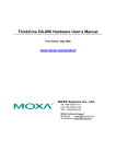
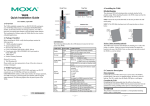
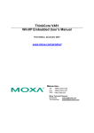
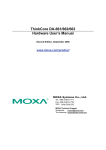
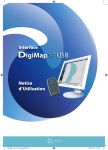
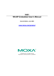
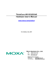
1
Rear View
LED Name
Power
ThinkCore V481-XPE
Quick Installation Guide
Storage
First Edition, November 2007
LAN 1
LAN 2
1. Overview
The ThinkCore V481 is an industrial, ready-to-run embedded computer
that supports VGA and audio, and comes with dual LAN ports, 8 serial
ports, a CompactFlash slot, and a USB port. The V481 is based on the
Intel x86 processor. The VGA interface makes the V481 especially
well-suited for industrial applications, such as SCADA, factory
automation, and applications that require an onsite HMI or monitor.
Top View
Optional Accessories
y Switching power adaptor for the ThinkCore V481:
60W, 24 VDC output, 100 to 240 VAC input (power cord must be
ordered separately); Order No.: 1117224250210
y Power Cords:
Power cord with Australian plug; Order No.: 1705010700510
Power cord with UK plug; Order No.: 1705010700410
Power cord with Euro plug; Order No.: 1705010700210
Power cord with straight US plug; Order No.: 1705010700110
NOTE: Notify your sales representative if any of the above items are
missing or damaged.
Wall or Cabinet Mounting
The ThinkCore V481 has built-in “ears” for attaching the embedded
computer to a wall or the inside of a cabinet. We suggest using two
screws per ear.
DIN-Rail Mounting
An aluminum DIN-Rail mounting kit is a standard accessory. If you need
to reattach the DIN-Rail mounting kit to the ThinkCore V481, make sure
the stiff metal spring is situated towards the top, as shown in the
following figures. Follow Steps 1 and 2 to mount the V481 on the
DIN-Rail.
STEP1: Insert the top of the
STEP2: The DIN-Rail attachment
DIN-Rail into the slot just below the unit will snap into place as shown.
stiff metal spring.
Front View
To remove V481 from Din-rail, simply reverse Steps 1 and 2.
LED Indicators
There are 6 LED indicators located on the front panel of the ThinkCore
V481.
3. ThinkCore V481 Panel Layout
5. Connector Description
Power Connector
Connect the 9 to 36 VDC LPS or Class 2 power line to the ThinkCore
V481’s terminal block. If the power is properly supplied, the Power LED
will light up.
Grounding the V481
Grounding and wire routing help limit the effects of noise due to
electromagnetic interference (EMI). Run the ground connection from the
ground screw to the grounding surface prior to connecting the power.
The following figures show the panel layouts of the ThinkCore V481.
P/N:1802004810020
—1—
LED Function
Power is on
No power is being received, or
Off
power error exists
Data is being written to or read
Yellow/Blinking
form the storage unit
Off
Storage unit is idle
Yellow
Tx/Link
Link LED
Disconnected, or short circuit
Off
exists
Orange
1000 Mbps Ethernet Mode
(LAN2 Only) (Gigabit Ethernet)
Mode LED
Green
100 Mbps Ethernet Mode
Off
10 Mbps Ethernet Mode
4. Installing the ThinkCore V481
2. Package Checklist
Before installing the ThinkCore V481, verify that the package contains
the following items:
y 1 ThinkCore V481
y Quick Installation Guide (this guide)
y Document and Software CD
y Din-rail Mounting Kit
y 100 cm RJ45-to-RJ45 Ethernet Cross-over Cable
y 20 cm Y-type Cable for Keyboard and Mouse
(CBL-MiniDIN6P/6Px2-20)
y Terminal Block to Power Jack Converter (includes Terminal Block)
y Product Warranty Statement
LED Color
Green
—2—
—3—
ATTENTION
This product is intended to be mounted to a well-grounded mounting
surface, such as a metal panel.
SG: The Shielded Ground (sometimes called
Protected Ground) contact is the right most
contact of the 3-pin power terminal block
connector, as viewed from the angle shown
here. Connect the SG wire to an appropriate
grounded metal surface.
VGA Connector
The ThinkCore V481 comes with a D-Sub 15-pin female connector to
connect a VGA CRT monitor.
PS/2 Connector
The ThinkCore V481 has a PS/2 connector for a PS/2 keyboard or PS/2
mouse connection. This 6-pin mini-DIN connector has the following pin
assignments.
PS/2 Connector Pin No.
Signal Definition
1
PS/2 keyboard data
2
PS/2 mouse data
3
GND
4
VCC
5
PS/2 keyboard clock
6
PS/2 mouse clock
A Y-type cable is included as a standard accessory for connecting a PS/2
keyboard and PS/2 mouse at the same time.
Ethernet Ports
Both the 10/100 and 10/100/1000 Mbps Ethernet ports use RJ45
connectors.
Pin
Signal
1
ETx+
1
8
2
ETx3
ERx+
6
ERxSerial Ports
The serial ports use DB9 connectors. Each port can be configured by
software for RS-232, RS-422, or RS-485. The pin assignments for the
ports are shown in the following table:
Pin
RS-232
RS-422
1
2
3
4
5
6
7
8
DCD
RxD
TxD
DTR
GND
DSR
RTS
CTS
TxDA(-)
TxDB(+)
RxDB(+)
RxDA(-)
GND
-------
RS-485
(4-wire)
TxDA(-)
TxDB(+)
RxDB(+)
RxDA(-)
GND
-------
—4—
RS-485
(2-wire)
----DataB(+)
DataA(-)
GND
-------
1 2 3 4 5
6 7 8 9
SO-DIMM Socket for Memory Module
The ThinkCore V481 has an internal 200-pin SO-DIMM socket for
installing a DDR SDRAM memory module. The V481-XPE comes with
a 512 MB DDR SDRAM Module pre-installed. You may also replace the
module with your own (128 MB to 1 GB) DDR SDRAM memory
module. To replace the module, first remove the bottom cover of the
V481 to expose the SO-DIMM socket.
Compact Flash Socket
The ThinkCore V481-XPE comes with a built-in 1 GB industrial
CompactFlash card to store the WinXP Embedded operating system. A
second CompactFlash socket is located inside the V481. Installing a
second CompactFlash memory card will not affect the operating system.
Remove the bottom cover of the V481 to install the second CompactFlash
card.
USB Hosts
The ThinkCore V481 supports two USB 2.0 hosts. Both hosts are UHCI,
Rev. 2.0 compliant and support Plug & Play and also hot swapping. Both
hosts can be used to connect any USB device, such as a keyboard, mouse,
USB flash disk, or USB CD-ROM. In addition, both USB ports support
system boot up, which is activated by changing BIOS settings.
Audio Interface
The ThinkCore V481 has an audio interface that follows the AC97
standard and supports speaker output and audio line input.
Power On/Off Button
The power on/off button is located above the power input terminal block.
The button supports the ATX power on/off function. By default, the
button is set for “instant off.” You may also configure the button for
“delay 4 seconds” to guard against shutting down the power
unintentionally. In this case, you must press the power button
continuously for at least 4 seconds to shut off the power.
ATTENTION
There is a risk of explosion if the battery is replaced by an incorrect type
of battery.
6. Powering on the V481
To power on the V481, connect the “terminal block to power jack
converter” to the V481’s DC terminal block (located on the left rear
panel), and then connect the power adaptor. Note that the Shielded
Ground wire should be connected to the right most pin of the terminal
block. It takes about 30 seconds for the system to boot up.
7. Starting the V481
Power on the V481 after connecting a monitor, keyboard, mouse, and
checking that the power source is ready. Once the operating system boots
up, the first step is to configure the Ethernet interface. The factory default
settings for the V481’s dual LANs are shown below. You can use a
cross-over Ethernet cable to connect directly from the PC to the V481 to
test if the LAN settings are correct.
LAN 1
LAN 2 (Gigabit)
Default IP Address
192.168.3.127
192.168.4.127
Netmask
255.255.255.0
255.255.255.0
8. Configuring the Ethernet Interface
Follow these steps to configure the Ethernet interface:
Step 1: [My Device] Æ [Control panel] Æ [Network Connections] to
enter the network setting page.
Step 2: Right-Click the LAN interface (e.g., Local Area Connection 2) to
configure and click property. A configuration window will pop up
Step 3: After inputting the proper IP address and netmask, click OK.
Reset Button
The reset button is designed to warm reboot the V481. Pressing the Reset
button initiates a hardware warm reboot. The button plays the same role
as a desktop PC’s reset button. After pressing the reset button, the system
will reboot automatically.
During normal use, you should NOT use the Reset Button. You should
only press the Reset Button if the software is not working properly. To
reset the system, work from the operating system environment by using
the corresponding software reboot function to protect the integrity of data
being transmitted or processed.
Real-time Clock
The embedded computer’s real-time clock is powered by a lithium battery.
We strongly recommend that you NOT replace the lithium battery
yourself. If the battery needs to be changed, please contact the MOXA
RMA service team.
—5—
Copyright © 2007
Moxa Systems Co., Ltd.
All rights reserved.
Reproduction without permission is prohibited.
Tel: +886-2-2910-1230
Fax: +886-2-2910-1231
www.moxa.com
[email protected]
—6—