1
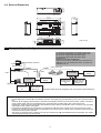
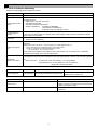
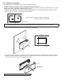
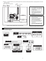
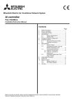
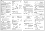
GB
Mitsubishi Electric Air Conditioner Network System
AI controller
PAC-YG63MCA
Installation/Instruction Manual
Table of Contents
Page
1.
2.
3.
4.
5.
6.
7.
8.
9.
10.
11.
Safety Precautions ..............................................1
Usage ..................................................................2
Parts List..............................................................2
Specifications ......................................................2
4-1.
Device Specifications .........................2
4-2.
External Dimensions...........................3
Example of System Configuration .......................3
Installation ...........................................................4
6-1.
Parts Purchased Separately...............4
6-2.
Installation Instructions .......................5
Wiring Instructions ...............................................6
7-1.
Terminal Diagram ...............................6
7-2.
Connecting the Power and M-NET
Transmission Lines.............................7
7-3.
Connecting the Sensors .....................8
(1) Channel 1 Pt100 Input........................8
(2) Channel 1 (Channel 2)
Analog Input ......................................8
7-4.
Connecting Alarm Setpoint Outputs ...9
Initial Settings ....................................................10
Dip Switch Functions .........................................12
LED Display Designations .................................13
10-1.
Alarm Setpoint Output and Error
Displays ............................................13
10-2.
Sensor and Communication Error
Displays ............................................13
System Operation Test......................................14
Before using the device, carefully read this installation/instruction manual to ensure proper operation.
Keep this manual for future reference and give it to the technician when the device is reinstalled or repaired.
1 Safety Precautions
• Thoroughly read the following safety precautions before use.
• Hazards that can occur from incorrect handling are classified by the symbols below:
Warning
Incorrect handling can result in death, serious injury, etc.
Caution
Incorrect handling can result in bodily injury and/or structure damage.
• After reading this manual, keep this manual for future reference. When the device is reinstalled or repaired, give this
manual to those who provide these services. When the user changes, make sure that the new user receives this
manual.
WARNING
Only a dealer or qualified technician should install, relocate,
reinstall, or repair the device.
Improper installation or repair may result in electrical shock or fire.
Do not make any modifications or alternations to the device.
Modifications or improper repair may result in electric shock or fire.
Consult your dealer for repair.
Properly install the device on a stable, load-bearing surface.
Device installed on an unstable surface may fall and cause injury.
All electrical work should be performed by an authorized
electrician according to local regulations and instructions
outlined in this manual.
Capacity shortage to the power supply circuit or improper installation
may result in electrical shock or fire.
Only use the specified cables; securely connect each so that the
terminals do not bear any cable weight.
Improperly connected or short-circuited cables may produce heat and
cause a fire.
Properly install the device according to the instructions in this
Installation/Instruction Manual.
Improper installation may result in electric shock or fire.
CAUTION
Do not install the device in a location where a flammable gas leak
may occur.
Gas may leak, collect around the device, ignite, and/or explode.
Do not install the device in a bathroom, kitchen, or any room
where steam could form. Condensation may develop and cause
electrical shock and/or the device to malfunction.
Do not install the device in environments where large amounts of
oil (including machine), sulfidizing gas, or acidic, alkaline,
chemical sprays are present.
These types of substances may damage internal parts, cause device
performance to be reduced, and cause electrical shock.
Use standard wires with the proper current capacity to avoid the
possibility of current leak, excessive heat, and/or fire.
Do not touch the main circuit board; also, make sure that dust
does not accumulate on the circuit board.
When installing the device in a hospital, communication facilities, etc., provide sufficient protection against frequency noise.
Power generators and inverters, high-frequency medical, or radio communication equipment may interfere with the normal operation of this device.
Subsequently, the device may also affect medical treatment, image broadcasting, etc., by creating frequency noise.
Include some slack in the power supply wires.
Tension on the wires may cause them to excessively heat up and/or
break, resulting in a fire.
Do not immerse the device in water.
Doing so may lead to electric shock or malfunctions.
The maximum applied voltage for the device is 24 VDC - do not
use with an AC power source. (The maximum applied voltage for
the M-NET terminal is 30 VDC.)
Using the incorrect voltage may result in device failure, ignition, and/
or fire.
Do not install the device in a location where there is direct
sunlight or where the temperature may become greater than 40°C
(104°F) or less than 0°C (32°F).
If the device is installed in such place, it may result in deformation or
malfunctions.
1
2 Usage
The AI controller measures temperature and humidity; it also has an alarm capability if the measurement data exceeds
defined setpoints. Historical measurement data can be displayed via only the G(B)-50A Web browser and TG-2000A.
Temperature and humidity cannot be displayed on the G-50A LCD.
Furthermore, an alarm can be output if measurement data exceeds a preset upper or lower limit.
The AI controller also features a function that interlocks M-NET devices for indoor units, etc. set in advance and performs
settings such as temperature control and operation/stoppage using measurement data values.
Caution: Usage Restrictions
• Mitsubishi Electric does not take financial responsibility for damages caused by issues beyond our control or special
circumstances (predicable or unpredictable); and secondary or accidental damages, and damages to other objects. We also
do not take financial responsibility for opportunities lost as a result of device failure, or electrical power failure at the enduser site.
Mitsubishi Electric does not take financial responsibility caused by end-users' requests including, but not limited to, device
testing, startup, readjustment and replacement.
• Do not use this device in disaster prevention security or "critical to life" applications.
3 Parts List
• The following parts should be included in your shipment:
Number
1
2
Part Name
AI controller
Installation/instruction manual (this document)
Quantity
1
1
* In addition to the parts listed above, see your local Mitsubishi Electric dealer to purchase the other parts necessary to operate this device (Refer to
section 6-1). Furthermore, depending on the application, other Mitsubishi Electric parts may be required.
For details, refer to "6. Installation".
4 Specifications
4-1. Device Specifications
Item
Power
Supply
Description
24 VDC±10%: 5 W
M-NET communication
Sensor
Measurement
target
Measurement
range
Pt100
(3-wire system)
Temperature
-30 to 60°C
[-22 to 140°F]
Temperature/
humidity
(Set by system
controller)
Temperature/
humidity
(Set by system
controller)
Ch2
Output
(*2)
Interlock
Function
Environment
Conditions
Dimensions
Weight
Time Backup
During Power
Failure
Installation
Environment
Analog
Analog
Interface
Input
Ch
Ch1
17 to 30 VDC (*1)
4 to 20 mADC
1 to 5 VDC
0 to 10 VDC
4 to 20 mADC
1 to 5 VDC
0 to 10 VDC
Upper/lower limit
alarm interlock output
(non-voltage contact)
Measurement error
±0.3%FS ±0.1°C (0.18°F)
(*3)
[at 25°C (77°F)]
±0.5%FS ±0.1°C (0.18°F)
(*3)
±0.5%FS ±0.1%RH
[at 25°C (77°F)]
±0.5%FS ±0.1°C (0.18°F)
(*3)
±0.5%FS ±0.1%RH
[at 25°C (77°F)]
Applied load
MAX: 24 VDC, 5 W
MIN: 5 VDC, 2 mW
* AC loads cannot be connected.
Screw terminal
block (M3) (*5)
Screw terminal
block (M3) (*5)
External
connection method
Screwless terminal
block (3 poles)
Screwless terminal
block (2 poles)
Screwless terminal
block (2 poles)
Screw terminal
block (M3.5) (*5)
Interlock M-NET devices according to measurement data values. (*4)
Operating temperature range
0 to 40°C [32°F to 104°F]
Storage temperature range
-20 to 60°C [-4°F to 140°F]
Humidity
30 to 90%RH (no condensation)
200 (W) × 120 (H) × 45 (D) mm / 77/8 (W) × 43/4 (H) × 125/32 (D) in
0.6 kg / 13/8 lb
Temperature
In the event of power failure or shut-off, the internal capacitor will continue to track time for approximately one week.
(The internal capacitor takes about 24 hours to fully charge; a replacement battery is not necessary.)
Inside a control panel (indoors)
* Use this product in a hotel, a business office environment or similar environment.
*1: Supply electric power from a power supply unit for the transmission line or an outdoor unit. Furthermore, the power consumption factor of the MNET circuitry of this unit is "1/4" (equivalent to one ME Remote Controller).
*2: Configure the dip switch settings for the analog input method to use while referring to "9. Dip Switch Functions".
*3: The measurement error for the system includes the measurement error for this unit, sensor, and wiring.
a%FS (full scale) = a% × ([measurement range's upper limit value] - [lower limit value])
*4: Settings for the interlock function are performed from the Maintenance Tool. For details, refer to the operation manual for the Maintenance Tool.
*5: M3 and M3.5 are sizes of the screw on the terminal block (ISO metric screw thread). The number indicates the screw diameter (mm).
2
26
(11/32)
4-2. External Dimensions
46 (113/16)
45 (125/32)
9 (3/8)
200 (77/8)
150 (529/32)
4.5
(3/16)
Al controller
PAC-YG63MCA
[ OUTPUT ] Non-voltage Contact Output
Ch1
Ch2
Alarm
Alarm
[ Output LEDs ]
Ch1
Ch2
Alarm
Alarm
110 (411/32)
120 (43/4)
N623
Al controller
PAC-YG63MCA
MODEL
SERVICE REF. PAC-YG60MCA-J
INPUT VOLTAGE
This device complies with Part15 of the FCC Rules.Operation is
subject to the following two conditions: (1)this device may not cause
harmful interference, and (2)this device must accept any interference
received, including interference that may cause undesired operation.
WEIGHT
[ INPUT ]
Ch1
JAPAN
[ 24 VDC Power Supply]
Ch2
4 to 20 mA / 1 to 5 V / 0 to 10 V
83.5 (35/16)
27 (13/32)
26
(19/32)
15
26 (11/32)
4 to 20 mA / 1 to 5 V / 0 to 10 V
IN
Unit: mm (in)
(11/32)
Pt100
DC24V;0.2A
0.6 kg / 13/ 8 lb
SERIAL No.
MADE
5 Example of System Configuration
(1) Channel 1 temperature or humidity sensor input
(2) Channel 2 temperature or humidity sensor input
(3) Channel 1 upper/lower limit alarm output
(4) Channel 2 upper/lower limit alarm output
<Restrictions>
Maximum of 50 units per G(B)-50A
However, the number of units that can be connected to a
G(B)-50A is up to 50 including this device, an indoor unit,
LOSSNAY unit, etc.
Centralized control line
Power supply unit
PAC-SC50KUA
M-NET
TB3
TB7
G-50A or GB-50A
Indoor control line
M-NET
AI controller
LAN
CITY MULTI
24 VDC Power
Supply
(3) (4)
AI controller
G(B)-50A Web or TG-2000A
24 VDC Power
Supply
(3) (4)
(1) (2)
Temperature sensor,
humidity sensor,
etc.
Upper/lower limit
alarm interlock
devices, etc.
(1) (2)
Temperature sensor,
humidity sensor,
etc.
Upper/lower limit
alarm interlock
devices, etc.
* This figure omits the power supply line and only shows the transmission line.
Note:
• For the shield ground of the M-NET centralized control line, use single-point grounding at the power unit for the transmission
line.
However, when supplying electric power to the M-NET centralized control line from the R410A series outdoor unit without
using a power supply unit for the transmission line, use single-point grounding at the TB7 of that outdoor unit.
Furthermore, when connecting the M-NET transmission line of this device to the M-NET indoor control line, use grounding
at the TB3 for each outdoor unit system.
• If the M-NET transmission line of this device is connected to an M-NET indoor control line and the outdoor unit is down
because, for example, the power supply is interrupted for servicing or there is a failure, the AI controller cannot be set and
monitored from the system controller.
• The sensor connected to the AI controller can only be monitored from G(B)-50A Web browser and TG-2000A. The sensor
cannot be monitored from the G-50A LCD.
3
6 Installation
6-1. Parts Purchased Separately
Prepare the following parts to install this device.
Required Part
Specification
Unit fixing screws
M4 screw × 4 (* M4: ISO metric screw thread)
Power supply for this
device
Commercially available power source: 24 VDC±10% 0.2 A (Minimum loading), SELV circuit, power line with
grounding terminal
Ripple noise: Lower than 200 mVp-p
Compatible specification
Authorized or CE marked products.
Subject to regulations: - IEC60950 (or EN60950)
- CISPR22/24 (or EN55022/24)
- IEC61000-3-2/3-3 (or EN61000-3-2/3-3)
Power supply for
sensors
A separate power supply for sensors may be required.
In the case of 24 VDC voltage, the capacity of the power supply for this unit can be increased so that the
power supply can be shared.
Power line
Use a sheathed vinyl cord or cable.
At least 0.75 mm² (AWG18)
M-NET transmission
line
Type of the cable: Sheathed vinyl cords or cable which comply with the following specifications or
equivalent.
• CPEV Φ1.2 mm to Φ1.6 mm • CVVS 1.25 mm² to 2 mm² (AWG 16 to 14)
* CPEV: PE insulated PVC jacketed shielded communication cable
* CVVS: PVC insulated PVC jacketed shielded control cable
PE: Polyethylene PVC: Polyvinyl chloride
Power needs to be supplied to the M-NET circuitry of this device. Use an outdoor unit or a separately
purchased power supply unit for the transmission line.
Signal lines
(Sensor input lines)
Shows the size of the electric wire (copper wire) that is adapted to the terminal block of this device. Refer
to the usage and cautionary items of the sensor when performing settings. However, use a line with shielded
line.
Electric wire size ···· (1) Solid wire: Φ0.65 mm (AWG21) - Φ1.2 mm (AWG16)
(2) Stranded wire: 0.75 mm² (AWG18) - 1.25 mm² (AWG16)
Single strand: At least Φ0.18 mm
[Parts to be Purchased Separately]
Name
Power supply unit
Model
Application
Remark
PAC-SC50KUA Power supply to the M-NET transmission line
This is not required when power is to be
supplied from an outdoor unit.
[Commercially available parts]
Part
Use
Remark
External 24 VDC
power source
Supplies power to the AI controller.
Refer to "Power supply for this device" and "Power
supply for sensors" in "Required Part" above for the
capacity of the power supply.
Sensor
Measures temperature and humidity.
Temperature sensor (PAC-SE40TSA) cannot be
connected.
4
6-2. Installation Instructions
The AI controller PAC-YG63MCA does not have a waterproof structure.
Be sure to install the AI controller inside a control panel that is located indoors.
Prepare a control panel capable of storing this device such as the one shown in the figure. (Install the device in a control
panel strong enough to withstand a weight of 0.6 kg [13/8 lb].)
This device can be installed horizontally, or as shown below, vertically. The following diagram also provides a rough
estimate of how much space is required around the installation.
100
(315/16)
100
100
(315/16)
(315/16)
100
(315/16)
Size of the device: 200 (W) × 120 (H) × 45 (D) mm/
77/8 (W) × 43/4 (H) × 125/32 (D) in
Unit: mm (in)
Note: The space shown above does not include space for peripherals. Additionally, the amount of space necessary varies according
to the functions that are used and the wiring method. Secure enough space appropriate for the type of installation.
(1) Fix the top of this device to the control panel at two points by loosely tightening the screws (M4) that were procured locally.
Fix the bottom in place with two screws and then tighten all four of the screws.
Screw pitch
150 (529/32)
110 (411/32)
Unit: mm (in)
(2) To remove the cover, as shown in the figure, remove the two screws for fixing the cover in place and then remove the cover by
unhooking the upper hook section from the lower case. To attach the cover, hook the upper hook section on the lower case and
then fix the cover in place with the two screws that were removed.
Hooks
Screws for fixing
the cover
Note: Two hooks are located on the upper section of the cover.
5
(3) Refer to "7. Wiring Instructions" and connect the wires for the power line, M-NET transmission line, output signal lines, and sensor
input signal lines.
M-NET Sensor input signal lines
Output
signal lines
AI
controller
Junction
terminal
block
Power line
Note:
• Do not install the sensor input signal
lines parallel to or near the M-NET
transmission line or power line. Also
avoid loop wiring.
• Be sure to ground this device, PACSC50KUA and 24 VDC Power
source. Measurement accuracy
may be affected if devices are not
grounded.
Relay
24 VDC
Power
source
+V
-V
FG
L
Caution:
• Perform wiring so that the terminal
block is not strained.
If strained, use a wire guide or
junction terminal to alleviate the
stress on the terminal block.
• Do not connect the wires directly from
the top of the control panel to the
terminal block.
Moisture may enter this device along
the wiring and cause electric shock or
fire.
N
PAC-SC50KUA
M-NET
Diagram Image (Installed within a Control Panel)
* The wiring in the diagram has been simplified.
7 Wiring Instructions
7-1. Terminal Diagram
Non-voltage Contact
Output
Function
Settings
LED17
M-NET
power on
SW01
Output
LEDs
SW02
SW03
SW08 SW09
LED03 / 02
CN03
M-NET
Address
Status LEDs
10s
1s
SW06
SW07
LED 11/ 12/ 13/ 14/ 15/ 16 (CPU power on)
M-NET
A/
B/
Analog Input
Setting
S
SW11
SW12
24 VDC Power Supply
V+ /
CN02
CN01
CN10
Channel 1
Pt100 Input
CN05
CN08
Channel 1
Analog Input
Channel 2
Analog Input
6
V- /
FG
7-2. Connecting the Power and M-NET Transmission Lines
Tightening torque for terminal screws: 1 N·m
Connect the M-NET transmission line of this device to a power
supply unit (PAC-SC50KUA) for the M-NET transmission line
or an outdoor unit (either a centralized control line or indoor
control line can be connected).
CN02
A/B/S
* Only the M-NET circuitry of this device receives the power from the
M-NET transmission line. The power consumption factor is "1/4"
(equivalent to one ME Remote Controller).
Field
Connections
(example)
(M2) (M1)
AI controller
S/B/A
M-NET
V+/V-/FG
R
Fuse
AC power Line
Arrester
Varistor
Noise
Filter
Varistor
U
U
24 VDC
Power
source
S
FG
* Functional
ground
Figure 7-1 Example of Connecting the Power Line and M-NET Transmission Line
Caution:
• Use a power line and M-NET transmission line that satisfy the specifications described in "6-1. Parts Purchased Separately".
• Attach a circuit comprising the following components to the supply primary side of the 24 VDC power supply.
(1) Varistor, (2) Arrester, (3) Noise filter, (4) Fuse
• It is important to pay attention to the polarity when connecting to the 24 VDC power supply terminal block.
Connecting the positive and negative in the reverse order will cause a failure.
• Fix the power line and M-NET transmission line in place on the outside to ensure that the terminal block is not affected by
any external force.
Not securely connecting and fixing the wires in place may cause heat generation and fire.
• Make sure that the copper wiring is not short-circuiting the plates (cover, lower case) or neighboring wires.
Cover the shielded line of the M-NET transmission line with materials such as vinyl tape and prevent short-circuiting with the
plates.
Note:
• If the M-NET transmission line of this device is connected to an M-NET indoor control line and the outdoor unit is down
because, for example, the power supply is interrupted for servicing or there is a failure, the AI controller cannot be set and
monitored from the system controller.
• Be sure to ground this device, PAC-SC50KUA and 24 VDC Power source.
Measurement accuracy may be affected if devices are not grounded.
7
7-3. Connecting the Sensors
• For channel 1, select one of the following four types: Pt100 detection, 4 to 20 mADC, 1 to 5 VDC, or 0 to 10 VDC analog
input.
• For channel 2, select one of the following three types: 4 to 20 mADC, 1 to 5 VDC, or 0 to 10 VDC analog input.
• The wire length depends on the specifications of the sensor. However, since the use of long wires makes the device
susceptible to noise, using wires shorter than 12 m (39.4 ft) is recommended. Use a shielded line for the sensor line
and connect to the FG terminal on this unit or the FG terminal on the control panel.
(1) Channel 1 Pt100 Input
To use these, various settings need to be configured. Refer to "8. Initial Settings".
B/A/B
CN10
Device side
Field
Connections
B A B
t°
Pt100 (3-wire system)
Caution:
• Use a 3-wire system for Pt100.
• A/B polarity is important for Pt100.
Be sure to match the polarity when using Pt100.
• Do not install the sensor input line parallel to or near the M-NET transmission
line or power line.
Also avoid loop wiring.
Furthermore, confirm the precautions for the sensor.
• Strip 12±1 mm (15/32 ±1/32 in) of the wire coating and insert firmly into the
terminal.
• Make sure that the copper wiring is not short-circuiting the plates (cover, lower
case) or neighboring wires.
• Perform wiring so that the terminal block is not strained.
If strained, use a wire guide or junction terminal to alleviate the stress on the
terminal block.
(2) Channel 1 (Channel 2) Analog Input (4 to 20 mADC, 1 to 5 VDC, 0 to 10 VDC)
To use these, various settings need to be configured.
Refer to "8. Initial Settings".
(b) When 4 to 20 mADC (type for which power is
supplied to the signal line) is connected
(a) When 1 to 5 VDC, 0 to 10 VDC, or 4 to 20 mADC
(type for which power is supplied to the sensor)
is connected
Device side
Device side
CN05
(CN08)
CN05
(CN08)
Field
Connections
Field
Connections
Power supply
Sensor
Sensor
Power supply
Caution:
• Select a power supply that is suitable for the sensor to be used.
• Do not install the sensor input line parallel to or near the M-NET transmission line or power line. Also avoid loop wiring.
Furthermore, confirm the precautions for the sensor.
• Strip 12±1 mm (15/32 ±1/32 in) of the wire coating and insert firmly into the terminal.
• Make sure that the copper wiring is not short-circuiting the plates (cover, lower case) or neighboring wires.
• Perform wiring so that the terminal block is not strained.
If strained, use a wire guide or junction terminal to alleviate the stress on the terminal block.
8
7-4. Connecting Alarm Setpoint Outputs (Non-valtage Contacts)
The maximum wire length is 100 m. However, since the use of long wires makes the device susceptible to noise, using
wires no more than 10 m long is recommended.
To use these, various settings need to be configured. Refer to "8. Initial Settings".
Load
Caution:
• To use X1 relay, obtain one that satisfies the following
specifications.
Operating coil
[Applied load]
MAX: 24 VDC, 5 W (Built-in diode)
MIN: 5 VDC, 2 mW (Built-in diode)
*1 AC loads cannot be connected.
*2 Provide a power supply (V1, V2) that matches the load
and relay to be used.
• To drive a direct load, use ones within the following.
[Applied load]
MAX: 24 VDC, 5 W
MIN: 5 VDC, 2 mW
* AC loads cannot be connected.
• Make sure that the copper wiring is not short-circuiting the
plates (cover, lower case) or neighboring wires.
• Perform wiring so that the terminal block is not strained.
If strained, use a wire guide or junction terminal to alleviate
the stress on the terminal block.
• Do not connect the wires directly from the top of the control
panel to the terminal block.
Moisture may enter this device along the wiring and cause
electric shock or fire.
Power supply
V1 (DC)
Power supply
Field
V2 (DC)
Connections
X1
CN03
Ch1
Device
side
Upper/lower
limit alarm
Ch2
Upper/lower
limit alarm
Tightening torque for terminal screws: 1 N·m.
* The contact of the internal relay is always ON during
detection of an upper/lower limit alarm. (Level output)
9
8 Initial Settings
After completing the procedures described in "6. Installation" and "7. Wiring Instructions", set the initial settings in
accordance with the procedure described below.
(1) M-NET address settings
10s
1s
SW06
SW07
Note:
• An address from 01 to 50 can be set.
• Set an address that is not the same as that of
another unit.
The address is set to "01" at factory default.
In the case of address "41"
(2) Use the dip switches to select functions.
Select the function required for each input/output channel to be used.
The switch assignment for each channel is shown below. Configure each of the settings while referring to "9. Dip Switch
Functions ".
• For channel 1, select one of the following four types: Pt100 detection, 4 to 20 mADC, 1 to 5 VDC, or 0 to 10 VDC analog input.
• For channel 2, select one of the following three types: 4 to 20 mADC, 1 to 5 VDC, or 0 to 10 VDC analog input.
(a) When using Pt100 detection (only channel 1 can be used)
Ch
Ch1
Setting
Pt100 used
Setting Switch
Pt100
To not use
(1) SW01-1
(2) SW01-3
ON
ON
OFF
OFF
(b) When using one of the analog inputs (4 to 20 mADC detection, 1 to 5 VDC detection, and 0 to 10 VDC detection)
Ch
4 to
Setting Switch 20 mADC
Setting
Ch1
Setting of sensor to use
(1) SW11-1
(2) SW11-2
(3) SW01-1
(4) SW01-2
(5) SW01-3
Ch2
Setting of sensor to use
(1) SW12-1
(2) SW12-2
(3) SW02-1
(4) SW02-2
1 to
5 VDC
0 to
10 VDC
To not
use
ON
ON
ON
OFF
OFF
OFF
ON
ON
OFF
OFF
OFF
OFF
ON
ON
OFF
OFF
OFF
OFF
OFF
OFF
ON
ON
ON
OFF
OFF
ON
ON
OFF
OFF
OFF
ON
ON
OFF
OFF
OFF
OFF
(c) When using upper/lower limit alarm interlock output
Ch
Setting
Setting Switch
To use
To not use
Ch1
Usage of upper/lower limit alarm interlock output
(1) SW01-5
ON
OFF
Ch2
Usage of upper/lower limit alarm interlock output
(1) SW02-5
ON
OFF
(d) Measurement data backup interval setting (for servicing)
Ch
Common
Setting
Measurement data backup interval setting
10
Setting Switch
1 min
2 min
5 min
10 min
(1) SW03-1
(2) SW03-2
OFF
OFF
OFF
ON
ON
OFF
ON
ON
(3) Turn on the power of this device.
Verify that the LED16 (CPU power on) and LED17 (M-NET power on) are lit.
(4) Set the time.
Set the current time from a system controller (G(B)-50A, TG-2000A) or a Maintenance Tool.
(5) Configure the settings of the system controller (G(B)-50A or TG-2000A).
Configure settings for the system controller (G(B)-50A or TG-2000A) such as the type of sensor to use and the measurement
range.
The main items that should be set are shown below.
(a) When using Pt100 detection (only channel 1 can be used)
Ch
Ch1
Setting
Setting with G(B)-50A or TG-2000A
Measurement category setting
Select temperature/humidity (Be sure to select
temperature.)
Measurement range setting
Set the upper limit and lower limit values
(Set a range from -30°C [-22°F] to 60°C [140°F].)
Measurement correction
Input the measurement temperature correction value
(offset value)
(b) When using an analog input (4 to 20 mADC detection, 1 to 5 VDC detection, or 0 to 10VDC detection)
Ch
Ch1
Ch2
Setting
Setting with G(B)-50A or TG-2000A
Measurement category setting
Select the temperature/humidity
Measurement range setting
Set the upper limit and lower limit values
Measurement correction
Input the measurement correction value (offset value)
Measurement category setting
Select the temperature/humidity
Measurement range setting
Set the upper limit and lower limit values
Measurement correction
Input the measurement correction value (offset value)
(c) When using upper/lower limit alarm interlock output
Ch
Setting
Setting with G(B)-50A or TG-2000A
Ch1
Upper/lower limit alarm detection value and
cancellation value settings
Upper/lower limit alarm detection value and cancellation
value settings
Ch2
Upper/lower limit alarm detection value and
cancellation value settings
Upper/lower limit alarm detection value and cancellation
value settings
(6) Settings for the interlock function are performed from the Maintenance Tool.
Perform settings such as interlock criteria for this device from Maintenance Tool.
For details, refer to the operating manual for the Maintenance Tool.
11
9 Dip Switch Functions
Supported
Channel
SW
SW01
1
Function
Selection of the input to use
2
Selection of the analog input
type (1)
3
4
SW02
Channel 1
–
Pt100
detection
Set the type of analog input for channel 1 (1).
* This should also be set in accordance with the selection
of analog input type (2) (SW11-1 and 2).
* The setting of SW01-2 is disabled when SW01-3 is ON.
Set to OFF
Specify whether to use channel 1 upper/lower limit
alarm interlock output.
Unused
Set to OFF
7
Unused
Set to OFF
8
Unused
1
Selection of the input to use
No
Yes
2
Selection of the analog input
type (1)
4 to 20 mADC/
1 to 5 VDC
detection
0 to 10 VDC
detection
Channel 2
No
Yes
Set to OFF
Specify whether to use the channel 2 input terminal.
Set the type of analog input for channel 2 (1).
* This should also be set in accordance with the selection
of analog input type (2) (SW12-1 and 2).
Unused
Set to OFF
Unused
Set to OFF
5
Selection of upper/lower limit
alarm interlock output use
6
Unused
Set to OFF
7
Unused
Set to OFF
8
Unused
Set to OFF
No
Yes
Specify whether to use channel 2 upper/lower limit
alarm interlock output.
2
Measurement data backup interval
1-minute interval: (2 hours worth)
2-minute interval: (4 hours worth)
5-minute interval: (10 hours worth)
10-minute interval: (20 hours worth)
3
Unused
Set to OFF
4
Unused
Set to OFF
5
Unused
Set to OFF
6
Unused
Set to OFF
7
Unused
Set to OFF
8
Unused
1
SW03-1
OFF
OFF
ON
ON
SW03-2
OFF
ON
OFF
ON
Set to back up measurement data to the fixed memory.
Excess past data will be erased.
Set to OFF
(Address 10s)
0 to 9 (decimal)
(Address 1s)
0 to 9 (decimal)
SW07
An address from 01 to 50 can be set.
Set an address that is not the same as that of another
unit.
1
Unused
Set to OFF
2
Unused
Set to OFF
3
Unused
Set to OFF
4
Unused
Set to OFF
5
Unused
Set to OFF
6
Unused
Set to OFF
1
Unused
Set to OFF
2
Unused
Channel 1
SW11-1
OFF
OFF
ON
ON
SW11-2
OFF
ON
OFF
ON
Set the type of analog input for channel 1 (2)
*1: This setting is not necessary when SW01-3 is ON.
Channel 2
Selection of analog input type (2)
0 to 10 VDC detection :
1 to 5 VDC detection :
Setting not possible
:
4 to 20 mADC detection:
SW12-1
OFF
OFF
ON
ON
SW12-2
OFF
ON
OFF
ON
Set the type of analog input for channel 2 (2)
1
1
2
Set to OFF
Selection of analog input type (2)
0 to 10 VDC detection :
1 to 5 VDC detection :
Setting not possible
:
4 to 20 mADC detection:
2
SW12
0 to 10 VDC
detection
Specify whether to use the channel 1 input terminal.
6
M-NET address
SW11
Yes
Unused
SW06
SW09
No
4 to 20 mADC/
1 to 5 VDC
detection
Remark
5
4
SW08
ON
Selection of upper/lower limit
alarm interlock output use
3
SW03
OFF
Set the dip switches for function selection according to the system to be used.
At factory default, the SW01, SW02, SW03, SW08, and SW09 dipswitches are all set to OFF; the SW11 and SW12
dipswitches are both set to ON, and the M-NET address is set to 01.
Be sure to turn off the power before changing switch settings.
12
10 LED Display Designations
The LEDs of this device indicate the upper/lower limit alarm interlock output status and error status of this device.
10-1.Alarm Setpoint Output and Error Displays
Display Item
Display LED
Content
Note
Power supply status
Output
status
Ch1, 2
(1) Power supply to CPU
:On,
:Flashing
: Lights when the CPU is energized.
(2) Power supply to M-NET
circuit
LED17
(M-NET power on)
: Lights when the M-NET is energized.
(1) Upper/lower limit alarm
interlock output status
LED03/02
(Output LEDs)
: Flashes during M-NET communication.
Output
Method
Level
Output
Error status (*1)
:Off,
LED16
(CPU power on)
(1) 4-digit error code
LED12/13/14/15
(Status display LEDs)
Ch1
Ch2
LED 03
LED 02
: Alarm output
: Alarm stop
: Alarm output
: Alarm stop
Refer to "10-2. Sensor and Communication Error
Displays".
*1: When a sensor error or communication error occurs, the error status is displayed.
10-2.Sensor and Communication Error Displays
If a sensor error or communication error occurs, a 4-digit error code will be repeatedly displayed according to the steps
shown below.
"Sensor and Communication Error Displays" consist of the following 10 steps. This operation is performed repeatedly to
indicate the 4-digit error code for the error.
Note
LED11
LED12
LED13
LED14
:On,
:Off,
:Flashing
LED15
Function
Remark
STEP1
"Sensor and
Communication Error
Displays"
Starting Point Indication
LEDs 12 to 15 flash 3 times
STEP2
Blank
Turn Off
Common
STEP3
Error code display (Binary number indication)
2
3=8
22=4
/
/
21=2
/
20=1
/
STEP4
STEP5
Blank
/
/
/
/
Error code 100's digit
indication
In the case of 6,
Blank
/
/
/
/
/
/
/
/
Turn Off
Error code 10's digit
indication
In the case of 0,
Error code 10's digit
STEP8
STEP9
Turn Off
Error code 100's digit
STEP6
STEP7
Error code 1000's digit
indication
In the case of 6,
Error code 1000's digit
Blank
Turn Off
Error code 1's digit
Error code 1's digit indication
In the case of 7,
Blank
Turn Off
STEP10
The error codes that are displayed for M-NET communication errors and sensor errors are as shown below.
Error Code
Description of Error
Error Code
Description of Error
6600
Multiple address error
6607
No ACK error
6601
M-NET polarity unset error
6608
No return of response frame
6602
Transmission processor hardware error
5010
Sensor trouble in Channel 1
6603
Transmission bus-busy error
5020
Sensor trouble in Channel 2
6606
Communications with transmission processor error
13
11 System Operation Test
Use the following procedure to confirm operation of the system.
(1) Configure the settings of this device and the system controller while referring to "8. Initial Settings".
(2) Confirm whether the measurement values of channel 1 and channel 2 are displayed on the system controller properly.
* Depending on the conditions, compare the measurement values with those of, for example, a commercially available portable
thermohygrometer.
If the measurement accuracy of the sensor used results in extreme differences in the measurement values, use the
measurement correction value (offset value) input function of the system controller to correct the measurement values.
(3) When upper/lower limit alarm interlock is to be used, input a value that exceeds the set alarm level and confirm whether the alarm
is displayed on the controller. Furthermore, confirm whether the alarm output operation takes place from the contact output at the
same time.
If there is a problem, check the wiring and settings.
For details on configuring settings, refer to "8. Initial Settings" and "9. Dip switch functions".
14
This product is designed and intended for use in the residential,
commercial and light-industrial environment.
This product at hand is
based on the following
EU regulations:
• Low Voltage Directive 2006/95/EC
• Electromagnetic Compatibility Directive
2004/108/EC
NOTE:
This equipment has been tested and found to comply with the limits for a Class
B digital device, pursuant to Part 15 of the FCC Rules. These limits are designed
to provide reasonable protection against harmful interference in a residential
installation. This equipment generates, uses and can radiate radio frequency
energy and, if not installed and used in accordance with the instructions, may
cause harmful interference to radio communications.
However, there is no guarantee that interference will not occur in a particular
installation.
If this equipment does cause harmful interference to radio or television
reception, which can be determined by turning the equipment off and on, the
user is encouraged to try to correct the interference by one or more of the
following measures:
- Reorient or relocate the receiving antenna.
- Increase the separation between the equipment and receiver.
- Connect the equipment into an outlet on a circuit different from that to which
the receiver is connected.
- Consult the dealer or an experienced radio/TV technician for help.
HEAD OFFICE: TOKYO BLDG., 2-7-3, MARUNOUCHI, CHIYODA-KU, TOKYO 100-8310, JAPAN
WT04975X02
Printed in Japan