1
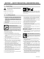
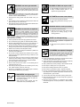
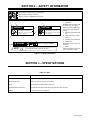
OM-815 October 1994 Eff. w/Serial Number KC310301 Processes Multiprocess Welding Description Mounting Rack For Up To Four XMT 300 Welding Power Sources With AUTO-LINK And Requiring 230/460 Volt Input Power R XMT 4-Rack Visit our website at www.MillerWelds.com From Miller to You Thank you and congratulations on choosing Miller. Now you can get the job done and get it done right. We know you don’t have time to do it any other way. That’s why when Niels Miller first started building arc welders in 1929, he made sure his products offered long-lasting value and superior quality. Like you, his customers couldn’t afford anything less. Miller products had to be more than the best they could be. They had to be the best you could buy. Today, the people that build and sell Miller products continue the tradition. They’re just as committed to providing equipment and service that meets the high standards of quality and value established in 1929. This Owner’s Manual is designed to help you get the most out of your Miller products. Please take time to read the Safety precautions. They will help you protect yourself against potential hazards on the worksite. We’ve made installation and operation quick and easy. With Miller you can count on years of reliable service with proper maintenance. And if for some reason the unit needs repair, there’s a Troubleshooting section that will help you Miller is the first welding figure out what the problem is. The parts list equipment manufacturer in will then help you to decide which exact part the U.S.A. to be registered to the ISO 9001 Quality System you may need to fix the problem. Warranty and Standard. service information for your particular model are also provided. Miller Electric manufactures a full line of welders and welding related equipment. For information on other quality Miller products, contact your local Miller distributor to receive the latest full line catalog or individual catalog sheets. To locate your nearest distributor or service agency call 1-800-4-A-Miller, or visit us at www.MillerWelds.com on the web. Working as hard as you do – every power source from Miller is backed by the most hassle-free warranty in the business. Miller offers a Technical Manual which provides more detailed service and parts information for your unit. To obtain a Technical Manual, contact your local distributor. Your distributor can also supply you with Welding Process Manuals such as SMAW, GTAW, GMAW, and GMAW-P. Call 1-800-4-A-MILLER for your local Miller distributor. Your distributor gives you ... Service You always get the fast, reliable response you need. Most replacement parts can be in your hands in 24 hours. Support Need fast answers to the tough welding questions? Contact your distributor. The expertise of the distributor and Miller is there to help you, every step of the way. Miller offers a Technical Manual which provides more detailed service and parts information for your unit. To obtain a Technical Manual, contact your local distributor. Your distributor can also supply you with Welding Process Manuals such as SMAW, GTAW, GMAW, and GMAW-P. For practical information on welding, process applications, and Miller products, visit our website at www.MillerWelds.com TABLE OF CONTENTS SECTION 1 – SAFETY PRECAUTIONS - READ BEFORE USING . . . . . . . . . . . . . . . . . . . . . . . . . . . . 1-1. Symbol Usage . . . . . . . . . . . . . . . . . . . . . . . . . . . . . . . . . . . . . . . . . . . . . . . . . . . . . . . . . . . . . . . . 1-2. Arc Welding Hazards . . . . . . . . . . . . . . . . . . . . . . . . . . . . . . . . . . . . . . . . . . . . . . . . . . . . . . . . . . 1-3. Additional Symbols For Installation, Operation, And Maintenance . . . . . . . . . . . . . . . . . . . . . 1-4. Principal Safety Standards . . . . . . . . . . . . . . . . . . . . . . . . . . . . . . . . . . . . . . . . . . . . . . . . . . . . . 1-5. EMF Information . . . . . . . . . . . . . . . . . . . . . . . . . . . . . . . . . . . . . . . . . . . . . . . . . . . . . . . . . . . . . . SECTION 2 – SAFETY INFORMATION . . . . . . . . . . . . . . . . . . . . . . . . . . . . . . . . . . . . . . . . . . . . . . . . . . . SECTION 3 – SPECIFICATIONS . . . . . . . . . . . . . . . . . . . . . . . . . . . . . . . . . . . . . . . . . . . . . . . . . . . . . . . . . SECTION 4 – INSTALLATION . . . . . . . . . . . . . . . . . . . . . . . . . . . . . . . . . . . . . . . . . . . . . . . . . . . . . . . . . . . 4-1. Selecting A Location And Moving Rack . . . . . . . . . . . . . . . . . . . . . . . . . . . . . . . . . . . . . . . . . . . 4-2. Installing Welding Power Source Onto Rack . . . . . . . . . . . . . . . . . . . . . . . . . . . . . . . . . . . . . . . 4-3. Welding Power Source Input Power Connections . . . . . . . . . . . . . . . . . . . . . . . . . . . . . . . . . . . 4-4. Common Work Connections . . . . . . . . . . . . . . . . . . . . . . . . . . . . . . . . . . . . . . . . . . . . . . . . . . . . 4-5. Paralleling Welding Power Sources For SMAW . . . . . . . . . . . . . . . . . . . . . . . . . . . . . . . . . . . . 4-6. Connecting Input Power To Rack . . . . . . . . . . . . . . . . . . . . . . . . . . . . . . . . . . . . . . . . . . . . . . . . SECTION 5 – MAINTENANCE & TROUBLESHOOTING . . . . . . . . . . . . . . . . . . . . . . . . . . . . . . . . . . . . 5-1. Routine Maintenance . . . . . . . . . . . . . . . . . . . . . . . . . . . . . . . . . . . . . . . . . . . . . . . . . . . . . . . . . . 5-2. Overload Protection . . . . . . . . . . . . . . . . . . . . . . . . . . . . . . . . . . . . . . . . . . . . . . . . . . . . . . . . . . . 5-3. Troubleshooting . . . . . . . . . . . . . . . . . . . . . . . . . . . . . . . . . . . . . . . . . . . . . . . . . . . . . . . . . . . . . . SECTION 6 – ELECTRICAL DIAGRAM . . . . . . . . . . . . . . . . . . . . . . . . . . . . . . . . . . . . . . . . . . . . . . . . . . . SECTION 7 – PARTS LIST . . . . . . . . . . . . . . . . . . . . . . . . . . . . . . . . . . . . . . . . . . . . . . . . . . . . . . . . . . . . . . WARRANTY 1 1 1 3 3 4 5 5 6 6 6 7 8 9 10 11 11 12 12 13 14 SECTION 1 – SAFETY PRECAUTIONS - READ BEFORE USING som _nd_5/97 1-1. Symbol Usage Means Warning! Watch Out! There are possible hazards with this procedure! The possible hazards are shown in the adjoining symbols. Y Marks a special safety message. . Means “Note”; not safety related. This group of symbols means Warning! Watch Out! possible ELECTRIC SHOCK, MOVING PARTS, and HOT PARTS hazards. Consult symbols and related instructions below for necessary actions to avoid the hazards. 1-2. Arc Welding Hazards Y The symbols shown below are used throughout this manual to call attention to and identify possible hazards. When you see the symbol, watch out, and follow the related instructions to avoid the hazard. The safety information given below is only a summary of the more complete safety information found in the Safety Standards listed in Section 1-4. Read and follow all Safety Standards. D If earth grounding of the workpiece is required, ground it directly with a separate cable – do not use work clamp or work cable. Y Only qualified persons should install, operate, maintain, and repair this unit. D Wear a safety harness if working above floor level. D Keep all panels and covers securely in place. Y During operation, keep everybody, especially children, away. D Clamp work cable with good metal-to-metal contact to workpiece or worktable as near the weld as practical. ELECTRIC SHOCK can kill. Touching live electrical parts can cause fatal shocks or severe burns. The electrode and work circuit is electrically live whenever the output is on. The input power circuit and machine internal circuits are also live when power is on. In semiautomatic or automatic wire welding, the wire, wire reel, drive roll housing, and all metal parts touching the welding wire are electrically live. Incorrectly installed or improperly grounded equipment is a hazard. D Do not touch electrode if you are in contact with the work, ground, or another electrode from a different machine. D Use only well-maintained equipment. Repair or replace damaged parts at once. Maintain unit according to manual. D Insulate work clamp when not connected to workpiece to prevent contact with any metal object. D Do not connect more than one electrode or work cable to any single weld output terminal. SIGNIFICANT DC VOLTAGE exists after removal of input power on inverters. D Turn Off inverter, disconnect input power, and discharge input capacitors according to instructions in Maintenance Section before touching any parts. D Do not touch live electrical parts. D Wear dry, hole-free insulating gloves and body protection. D Insulate yourself from work and ground using dry insulating mats or covers big enough to prevent any physical contact with the work or ground. D Do not use AC output in damp areas, if movement is confined, or if there is a danger of falling. D Use AC output ONLY if required for the welding process. D If AC output is required, use remote output control if present on unit. D Disconnect input power or stop engine before installing or servicing this equipment. Lockout/tagout input power according to OSHA 29 CFR 1910.147 (see Safety Standards). D Properly install and ground this equipment according to its Owner’s Manual and national, state, and local codes. D Keep your head out of the fumes. Do not breathe the fumes. D Always verify the supply ground – check and be sure that input power cord ground wire is properly connected to ground terminal in disconnect box or that cord plug is connected to a properly grounded receptacle outlet. D When making input connections, attach proper grounding conductor first – double-check connections. D Frequently inspect input power cord for damage or bare wiring – replace cord immediately if damaged – bare wiring can kill. D Turn off all equipment when not in use. D Do not use worn, damaged, undersized, or poorly spliced cables. D Do not weld in locations near degreasing, cleaning, or spraying operations. The heat and rays of the arc can react with vapors to form highly toxic and irritating gases. D Do not drape cables over your body. FUMES AND GASES can be hazardous. Welding produces fumes and gases. Breathing these fumes and gases can be hazardous to your health. D If inside, ventilate the area and/or use exhaust at the arc to remove welding fumes and gases. D If ventilation is poor, use an approved air-supplied respirator. D Read the Material Safety Data Sheets (MSDSs) and the manufacturer’s instructions for metals, consumables, coatings, cleaners, and degreasers. D Work in a confined space only if it is well ventilated, or while wearing an air-supplied respirator. Always have a trained watchperson nearby. Welding fumes and gases can displace air and lower the oxygen level causing injury or death. Be sure the breathing air is safe. D Do not weld on coated metals, such as galvanized, lead, or cadmium plated steel, unless the coating is removed from the weld area, the area is well ventilated, and if necessary, while wearing an air-supplied respirator. The coatings and any metals containing these elements can give off toxic fumes if welded. OM-815 Page 1 ARC RAYS can burn eyes and skin. Arc rays from the welding process produce intense visible and invisible (ultraviolet and infrared) rays that can burn eyes and skin. Sparks fly off from the weld. D Wear a welding helmet fitted with a proper shade of filter to protect your face and eyes when welding or watching (see ANSI Z49.1 and Z87.1 listed in Safety Standards). D Wear approved safety glasses with side shields under your helmet. D Use protective screens or barriers to protect others from flash and glare; warn others not to watch the arc. D Wear protective clothing made from durable, flame-resistant material (leather and wool) and foot protection. BUILDUP OF GAS can injure or kill. D Shut off shielding gas supply when not in use. D Always ventilate confined spaces or use approved air-supplied respirator. HOT PARTS can cause severe burns. D Do not touch hot parts bare handed. D Allow cooling period before working on gun or torch. MAGNETIC FIELDS can affect pacemakers. WELDING can cause fire or explosion. Welding on closed containers, such as tanks, drums, or pipes, can cause them to blow up. Sparks can fly off from the welding arc. The flying sparks, hot workpiece, and hot equipment can cause fires and burns. Accidental contact of electrode to metal objects can cause sparks, explosion, overheating, or fire. Check and be sure the area is safe before doing any welding. D Protect yourself and others from flying sparks and hot metal. D Do not weld where flying sparks can strike flammable material. D Remove all flammables within 35 ft (10.7 m) of the welding arc. If this is not possible, tightly cover them with approved covers. D Be alert that welding sparks and hot materials from welding can easily go through small cracks and openings to adjacent areas. D Watch for fire, and keep a fire extinguisher nearby. D Be aware that welding on a ceiling, floor, bulkhead, or partition can cause fire on the hidden side. D Do not weld on closed containers such as tanks, drums, or pipes, unless they are properly prepared according to AWS F4.1 (see Safety Standards). D Connect work cable to the work as close to the welding area as practical to prevent welding current from traveling long, possibly unknown paths and causing electric shock and fire hazards. D Do not use welder to thaw frozen pipes. D Remove stick electrode from holder or cut off welding wire at contact tip when not in use. D Wear oil-free protective garments such as leather gloves, heavy shirt, cuffless trousers, high shoes, and a cap. D Remove any combustibles, such as a butane lighter or matches, from your person before doing any welding. FLYING METAL can injure eyes. D Welding, chipping, wire brushing, and grinding cause sparks and flying metal. As welds cool, they can throw off slag. D Wear approved safety glasses with side shields even under your welding helmet. OM-815 Page 2 D Pacemaker wearers keep away. D Wearers should consult their doctor before going near arc welding, gouging, or spot welding operations. NOISE can damage hearing. Noise from some processes or equipment can damage hearing. D Wear approved ear protection if noise level is high. CYLINDERS can explode if damaged. Shielding gas cylinders contain gas under high pressure. If damaged, a cylinder can explode. Since gas cylinders are normally part of the welding process, be sure to treat them carefully. D Protect compressed gas cylinders from excessive heat, mechanical shocks, slag, open flames, sparks, and arcs. D Install cylinders in an upright position by securing to a stationary support or cylinder rack to prevent falling or tipping. D Keep cylinders away from any welding or other electrical circuits. D Never drape a welding torch over a gas cylinder. D Never allow a welding electrode to touch any cylinder. D Never weld on a pressurized cylinder – explosion will result. D Use only correct shielding gas cylinders, regulators, hoses, and fittings designed for the specific application; maintain them and associated parts in good condition. D Turn face away from valve outlet when opening cylinder valve. D Keep protective cap in place over valve except when cylinder is in use or connected for use. D Read and follow instructions on compressed gas cylinders, associated equipment, and CGA publication P-1 listed in Safety Standards. 1-3. Additional Symbols For Installation, Operation, And Maintenance FIRE OR EXPLOSION hazard. MOVING PARTS can cause injury. D Do not install or place unit on, over, or near combustible surfaces. D Do not install unit near flammables. D Do not overload building wiring – be sure power supply system is properly sized, rated, and protected to handle this unit. D Keep away from moving parts such as fans. D Keep all doors, panels, covers, and guards closed and securely in place. FALLING UNIT can cause injury. H.F. RADIATION can cause interference. D Use lifting eye to lift unit only, NOT running gear, gas cylinders, or any other accessories. D Use equipment of adequate capacity to lift and support unit. D If using lift forks to move unit, be sure forks are long enough to extend beyond opposite side of unit. D OVERUSE can cause OVERHEATING D D Allow cooling period; follow rated duty cycle. D Reduce current or reduce duty cycle before starting to weld again. D Do not block or filter airflow to unit. D D D High-frequency (H.F.) can interfere with radio navigation, safety services, computers, and communications equipment. D Have only qualified persons familiar with electronic equipment perform this installation. The user is responsible for having a qualified electrician promptly correct any interference problem resulting from the installation. If notified by the FCC about interference, stop using the equipment at once. Have the installation regularly checked and maintained. Keep high-frequency source doors and panels tightly shut, keep spark gaps at correct setting, and use grounding and shielding to minimize the possibility of interference. STATIC (ESD) can damage PC boards. D Put on grounded wrist strap BEFORE handling boards or parts. D Use proper static-proof bags and boxes to store, move, or ship PC boards. ARC WELDING can cause interference. MOVING PARTS can cause injury. D Keep away from moving parts. D Keep away from pinch points such as drive rolls. D D WELDING WIRE can cause injury. D Do not press gun trigger until instructed to do so. D Do not point gun toward any part of the body, other people, or any metal when threading welding wire. D D D Electromagnetic energy can interfere with sensitive electronic equipment such as computers and computer-driven equipment such as robots. D Be sure all equipment in the welding area is electromagnetically compatible. To reduce possible interference, keep weld cables as short as possible, close together, and down low, such as on the floor. Locate welding operation 100 meters from any sensitive electronic equipment. Be sure this welding machine is installed and grounded according to this manual. If interference still occurs, the user must take extra measures such as moving the welding machine, using shielded cables, using line filters, or shielding the work area. 1-4. Principal Safety Standards Safety in Welding and Cutting, ANSI Standard Z49.1, from American Welding Society, 550 N.W. LeJeune Rd, Miami FL 33126 Safety and Health Standards, OSHA 29 CFR 1910, from Superintendent of Documents, U.S. Government Printing Office, Washington, D.C. 20402. Recommended Safe Practices for the Preparation for Welding and Cutting of Containers That Have Held Hazardous Substances, American Welding Society Standard AWS F4.1, from American Welding Society, 550 N.W. LeJeune Rd, Miami, FL 33126 National Electrical Code, NFPA Standard 70, from National Fire Protection Association, Batterymarch Park, Quincy, MA 02269. Safe Handling of Compressed Gases in Cylinders, CGA Pamphlet P-1, from Compressed Gas Association, 1235 Jefferson Davis Highway, Suite 501, Arlington, VA 22202. Code for Safety in Welding and Cutting, CSA Standard W117.2, from Canadian Standards Association, Standards Sales, 178 Rexdale Boulevard, Rexdale, Ontario, Canada M9W 1R3. Safe Practices For Occupation And Educational Eye And Face Protection, ANSI Standard Z87.1, from American National Standards Institute, 1430 Broadway, New York, NY 10018. Cutting And Welding Processes, NFPA Standard 51B, from National Fire Protection Association, Batterymarch Park, Quincy, MA 02269. OM-815 Page 3 1-5. EMF Information Considerations About Welding And The Effects Of Low Frequency Electric And Magnetic Fields Welding current, as it flows through welding cables, will cause electromagnetic fields. There has been and still is some concern about such fields. However, after examining more than 500 studies spanning 17 years of research, a special blue ribbon committee of the National Research Council concluded that: “The body of evidence, in the committee’s judgment, has not demonstrated that exposure to powerfrequency electric and magnetic fields is a human-health hazard.” However, studies are still going forth and evidence continues to be examined. Until the final conclusions of the research are reached, you may wish to minimize your exposure to electromagnetic fields when welding or cutting. To reduce magnetic fields in the workplace, use the following procedures: OM-815 Page 4 1. Keep cables close together by twisting or taping them. 2. Arrange cables to one side and away from the operator. 3. Do not coil or drape cables around your body. 4. Keep welding power source and cables as far away from operator as practical. 5. Connect work clamp to workpiece as close to the weld as possible. About Pacemakers: Pacemaker wearers consult your doctor first. If cleared by your doctor, then following the above procedures is recommended. SECTION 2 – SAFETY INFORMATION mod1.1 2/93 Read all safety messages throughout this manual. Obey all safety messages to avoid injury. Learn the meaning of WARNING and CAUTION. 1 2 2 WARNING 3 ELECTRIC SHOCK can kill. • Do not touch live electrical parts. • Disconnect input power before installing or servicing. Safety Alert Symbol 2 Signal Word WARNING means possible death or serious injury can happen. CAUTION MOVING PARTS can injure. 4 1 • Keep away from moving parts. • Keep all panels and covers closed when operating. CAUTION means possible minor injury or equipment damage can happen. 3 Statement Of Hazard And Result 4 Safety Instructions To Avoid Hazard 5 Hazard Symbol (If Available) 6 Safety Banner 5 6 WARNING READ SAFETY BLOCKS at start of Section 3-1 before proceeding. Read safety blocks for each symbol shown. 7 7 NOTE Turn Off switch when using high frequency. NOTE Special instructions for best operation – not related to safety. Figure 2-1. Safety Information SECTION 3 – SPECIFICATIONS Table 3-1. Rack Specifications Description Overall Dimensions Height: 48-5/8 in (1.23 m); Width: 63 in (1.60 m); Depth: 40 in (1.02 m) Required Input Power 230 Or 460 Volts AC; 50/60 Hz; Three-Phase Weight Net: 850 lb (385.6 kg); Ship: 860 lb (390.1 kg) Required Welding Power Source 300 Amp XMT With AUTO-LINK Requiring 230 Or 460 Volts Input Power Capacity 4 Welding Power Sources Maximum OM-815 Page 5 SECTION 4 – INSTALLATION 4-1. Selecting A Location And Moving Rack WARNING ELECTRIC SHOCK can kill. • • FUMES can be hazardous; LACK OF F RESH AI R AND PRO PER VENTILATION can be harmful. Do not touch live electrical parts. • • Disconnect input power conductors from deenergized supply line BEFORE moving rack. FIRE OR EXPLOSION can result from placing unit on, over, or near combustible surfaces. • • Do not breathe welding fumes. Place unit only where there is a good fresh air supply and proper ventilation. FAL L I NG EQ UI PM ENT can cau se serious personal injury and equipment damage. Do not locate unit on, over, or near combustible surfaces. Do not install unit near flammables. • Move unit with crane or fork lift vehicle of adequate capacity. swarn11.1* 3/93 1 1 Lifting Eye Use lifting eye to move unit. 2 Lifting Forks If using lifting forks, be sure forks are fully inserted. 2 ST-158 366 Figure 4-1. Location And Movement Of Rack 4-2. Installing Welding Power Source Onto Rack 1 6 As Shipped Bracket Remove user-supplied bolt or lock if applicable. 2 Securing Bolts Loosen. In Use 3 Front Bracket Swing end near rack center away from rack. 4 Rear Bracket 5 Securing Bracket Place welding power source on rack so rear is against rear bracket and securing bracket is centered between welding power source feet. 4 Swing front bracket back into position. 1 Tighten securing bolts. 2 5 3 Reinstall user-supplied bolt or lock if applicable. 6 Weld Cable Hanger ST-158 332 / S-0548 / ST-151 268-A Figure 4-2. Welding Power Source Installation OM-815 Page 6 4-3. Welding Power Source Input Power Connections WARNING ELECTRIC SHOCK can kill. • • • • Do not touch live electrical parts. Turn Off welding power source, and disconnect input power to rack before inspecting or installing. Have only qualified persons install unit. Installation must meet National Electrical Code and all other codes. NOTE swarn3.1* 2/93 When installing conductors from the welding power source, torque the Power circuit breaker terminals and grounding terminal to 40 in-lbs (4.5 N·m). 1 2 5 7 8 Tools Needed: 6 4 3 ST-158 333 / ST-151 269-B Have only qualified persons make this installation. 1 Control Box 2 Access Door Open access door with same number as welding power source location. 3 Welding Power Source Input Power Cord 4 Strain Relief Connector 8 Insert input power cord through strain relief into entry hole for opened access door. 5 Grounding Conductor – Green Or Green With Yellow Stripe(s) 6 Input Conductors 7 Power Circuit Breaker Terminals Grounding Terminal Install input conductors from welding power source to Power circuit breaker. Install grounding conductor to grounding terminal. Close and secure access door. Figure 4-3. Welding Power Source Input Power Connections Table 4-1. Weld Cable Size* Total Cable (Copper) Length In Weld Circuit Not Exceeding 100 ft (30 m) Or Less Welding Amperes 10 To 60% Duty Cycle 60 Thru 100% Duty Cycle 100 150 200 250 300 350 400 500 600 700 800 900 1000 1250 1500 4 3 3 2 1 1/0 1/0 2/0 3/0 4/0 4/0 2-2/0 2-2/0 2-3/0 2-4/0 4 3 2 1 1/0 2/0 2/0 3/0 4/0 2-2/0 2-2/0 2-3/0 2-3/0 2-4/0 3-3/0 150 ft (45 m) 200 ft (60 m) 250 ft (70 m) 300 ft (90 m) 350 ft (105 m) 400 ft (120 m) 1/0 3/0 4/0 2-2/0 2-3/0 2-3/0 2-4/0 3-3/0 3-4/0 3-4/0 4-4/0 4-4/0 1/0 3/0 4/0 2-2/0 2-3/0 2-4/0 2-4/0 3-3/0 3-4/0 4-4/0 4-4/0 10 Thru 100% Duty Cycle 4 2 1 1/0 2/0 3/0 3/0 4/0 2-2/0 2-3/0 2-3/0 2-4/0 2-4/0 3-3/0 3-4/0 3 1 1/0 2/0 3/0 4/0 4/0 2-2/0 2-3/0 2-4/0 2-4/0 3-3/0 3-3/0 4-3/0 4-4/0 2 1/0 2/0 3/0 4/0 2-2/0 2-2/0 2-3/0 2-4/0 3-3/0 3-4/0 3-4/0 4-3/0 4-4/0 1 2/0 3/0 4/0 2-2/0 2-3/0 2-3/0 2-4/0 3-3/0 3-4/0 3-4/0 4-4/0 4-4/0 *Weld cable size (AWG) is based on either a 4 volts or less drop or a current density of at least 300 circular mils per ampere. S-0007-D OM-815 Page 7 4-4. Common Work Connections WARNING ELECTRIC SHOCK can kill. • • • • • ARCING can burn skin or damage electrical equipment. Do not touch live electrical parts. • Turn Off welding power sources by placing Power circuit breakers in the Off position before making any weld output connections. Do not connect welding output of different polarities to the same structure. See ANSI Z49.1 and OSHA Title 29, Chapter XVII, Part 1910, Subpart Q (addresses at beginning of manual). Do not handle or come in contact with two live electrodes at the same time. • Do not change position of the welding cable connectors while welding. Be sure the connectors are secure in receptacles before welding. INADEQUATE WORK CABLE CONNECTIONS can cause serious damage to input power service and create a hazardous condition. • Connect an electrical cable of adequate size between the isolated terminal and the workpiece whenever any welding power sources are connected to the isolated terminal. The following procedure is for Electrode Positive welding connections. 3 1 2 Positive (+) Weld Output Cables Determine cable lengths and sizes according to welding power source Owner’s Manual. 5 2 Isolated Terminal 3 Negative (–) Weld Output Cables Determine cable sizes according to welding power source Owner’s Manual. Cable must reach from negative (–) output receptacle to isolated terminal. 4 4 2 4 Common Negative (–) Weld Output Cable Cable must be able to carry combined weld output of all welding power sources using common work connections. Use Table 4-1 to select proper cable size. 5 Terminal Lugs Use lugs of proper amperage capacity and hole size for connecting to isolated terminal. 3 GTAW GMAW SMAW 1 GTAW GMAW SMAW Figure 4-4. Common Work Connections OM-815 Page 8 For Electrode Negative, reverse cable connections. Positive (+) weld output cables connect to isolated terminal, negative (–) weld output cables go to electrode. Common weld output cable is positive. ST-155 335 / Ref. ST-154 540-A 4-5. Paralleling Welding Power Sources For SMAW WARNING ELECTRIC SHOCK can kill. • • • • • ARCING can burn skin or damage electrical equipment. Do not touch live electrical parts. Turn Off welding power sources by placing Power circuit breakers in the Off position before making any weld output connections. Do not connect welding output of different polarities to the same structure. See ANSI Z49.1 and OSHA Title 29, Chapter XVII, Part 1910, Subpart Q (addresses at beginning of manual). Do not handle or come in contact with two live electrodes at the same time. • • INADEQUATE WORK CABLE CONNECTIONS can cause serious damage to input power service and create a hazardous condition. • UNDERSIZED WELDING CABLES can cause fire. • Do not change position of the welding cable connectors while welding. Be sure the connectors are secure in receptacles before welding. Connect an electrical cable of adequate size between the isolated terminal and the workpiece whenever any welding power sources are connected to the isolated terminal. Use single cables of adequate capacity to carry the total combined amperage of the paralleled welding power sources. Set the Amperage/Voltage control on all paralleled welding power sources to the same value. The isolated terminal may be used as a common connection point if no other connections are made to it. The procedure shown is for Electrode Positive welding connections. 1 Weld Output Cables Determine cable sizes according to welding power source Owner’s Manual. Cables must reach cable connection point. Cables connected together must be the same polarity. 2 Connection Point Cover with proper insulating material after making connections. 1 3 1 4 4 4 2 SMAW – + Terminal Lugs Use lugs of proper amperage capacity and hole size for connection. Common Weld Output Cable Cable must be able to carry combined weld output of all welding power sources connected in parallel. Use Table 4-1 to select proper cable size. For Electrode Negative, reverse cable connections. Positive (+) weld output cables connect to work, negative (–) weld output cables go to electrode. 1 Securely cover connection with proper insulating material. 3 4 ST-158 334 / Ref. ST-154 540-A Figure 4-5. Paralleling Welding Power Sources For SMAW OM-815 Page 9 4-6. Connecting Input Power To Rack WARNING ELECTRIC SHOCK can kill. • • • • Do not touch live electrical parts. Turn Off welding power sources before inspecting or installing rack. Have only qualified persons install rack. Installation must meet National Electrical Code and all other codes. swarn3.1* 2/93 Have only qualified persons make this installation. 1 Rear Control Box Center 2 Access Panel Remove access panel. 1 2 3 Line Disconnect Device Of Proper Rating 4 Input Conductors 5 Grounding Conductor Select size and length using Table 4-2. Conductors must be able to carry the combined amperage draw of all welding power sources mounted on the rack. Conductor insulation must comply with national, state, and local electrical codes. Use lugs of proper amperage capacity and correct hole size. 6 User-Supplied Strain Relief Connector Insert conductors through strain relief. 7 Input Terminal Block 8 Line Terminals 9 Ground Terminal Connect grounding conductor to ground terminal first. Then connect input conductors to line terminals. Reinstall access panel. 8 4 7 3 Install grounding conductor and input conductors in conduit or equivalent to deenergized line disconnect device. Connect grounding conductor first, then line input conductors. 10 Be sure grounding conductor goes to an earth ground. 10 Overcurrent Protection 6 5 9 5 Select type and size using Table 4-2. Install into deenergized line disconnect device (fused disconnect switch shown). ST-151 270-C Figure 4-6. Input Power Connections OM-815 Page 10 Table 4-2. Electrical Service Requirements* Input Voltage 230 460 Recommended Standard Fuse Or Circuit Breaker Rating In Amperes1 250 125 Input Conductor Size In AWG/Kcmil2 1/0 4 229 (70) 397 (121) 4 6 Max Input Conductor Length In Feet (Meters)3 Grounding Conductor Size In AWG/Kcmil4 * These values are calculated from the 1993 edition of the National Electrical Code (NEC). 1 Recommended fuse or circuit breaker size is that closest to 150% of rated input amperage of the welding power source. Article 630-12(a) of NEC allows fuse or circuit breaker sizing up to 200% of rated input amperage. 2 Input conductor size is for insulated copper wire with 75°C rating with not more than three single current-carrying conductors in a cable or raceway (Table 310-16 of NEC). 3 Maximum length is to prevent more than a 3% voltage drop between service entrance and input terminals of the welding power source (Articles 210-19(a) and 215-2(b) of NEC). 4 The grounding conductor shall be colored or identified as specified in the NEC. Grounding conductor size for copper wire is not required to be larger than input conductor (Article 250-95 of NEC). Ref. S-0092-G SECTION 5 – MAINTENANCE & TROUBLESHOOTING WARNING ELECTRIC SHOCK can kill. • • Do not touch live electrical parts. Turn Off welding power sources, and disconnect input power to rack before inspecting, maintaining, or servicing. Maintenance to be performed only by qualified persons. 5-1. Routine Maintenance 3 Months Turn Off all power before maintaining. Tape Or Replace Cracked Cables 6 Months See Section 7 Replace Unreadable Labels OR –– Blow Out Or Vacuum Inside During Heavy Service, Clean Monthly Clean And Tighten Weld Connections ST-151 267-B Figure 5-1. Maintenance Schedule OM-815 Page 11 5-2. Overload Protection 1 Power Circuit Breakers CB1-CB4 Each Power circuit breaker CB1 through CB4 protects the welding power source connected to it from overload. If a Power circuit breaker opens, the matching welding power source would shut down. Manually reset the Power circuit breaker. 1 ST-158 333 / Ref. ST-155 839 / Ref. ST-151 269-B Figure 5-2. Circuit Breaker Locations 5-3. Troubleshooting WARNING ELECTRIC SHOCK can kill. • • Do not touch live electrical parts. Turn Off welding power sources, and disconnect input power to rack before inspecting, maintaining, or servicing. Troubleshooting to be performed only by qualified persons. Table 5-1. Rack Trouble Trouble No weld output from any welding power sources; units completely inoperative. No weld output from one welding power source. OM-815 Page 12 Remedy Section Place line disconnect switch in On position. 4-6 Check line fuse(s) and replace if needed. Reset circuit breakers. 4-6 Check for proper input power connections to rack. 4-6 Place applicable Power circuit breaker in On position. 5-2 Check for proper input power connections to welding power source. 4-3 Check applicable welding power source according to its manual. –– SECTION 6 – ELECTRICAL DIAGRAM SA-155 857 Figure 6-1. Circuit Diagram For Rack Control Box OM-815 Page 13 SECTION 7 – PARTS LIST Item No. Part No. Description Quantity Figure 7-1. Main Assembly ... ... ... ... ... ... ... ... ... ... ... ... ... ... 1 2 3 4 5 6 7 8 9 10 11 12 13 14 . . . 155 878 . . . 032 473 . . +155 844 . . . 151 928 . . . 148 851 . . . 049 399 . . . 153 926 . . . 151 946 . . . 153 927 . . . 134 327 . . . 155 156 . . . 147 380 . . . 147 331 . . . . Fig 7-2 .. .. .. .. .. .. .. .. .. .. .. .. .. .. COVER, top . . . . . . . . . . . . . . . . . . . . . . . . . . . . . . . . . . . . . . . . . . . . . . . . . . . . . . . . . . . . . . GASKET, lift eye . . . . . . . . . . . . . . . . . . . . . . . . . . . . . . . . . . . . . . . . . . . . . . . . . . . . . . . . . . BASE . . . . . . . . . . . . . . . . . . . . . . . . . . . . . . . . . . . . . . . . . . . . . . . . . . . . . . . . . . . . . . . . . . . . RETAINER, hold down brkt . . . . . . . . . . . . . . . . . . . . . . . . . . . . . . . . . . . . . . . . . . . . . . . . . BRACKET, nut-sert . . . . . . . . . . . . . . . . . . . . . . . . . . . . . . . . . . . . . . . . . . . . . . . . . . . . . . . . NUT, speed push-on-type .312 stud .625 OD x .45 . . . . . . . . . . . . . . . . . . . . . . . . . . . . . BRACKET, hold down right . . . . . . . . . . . . . . . . . . . . . . . . . . . . . . . . . . . . . . . . . . . . . . . . . WASHER, flat nyl .317 ID x .500 OD x .032thk . . . . . . . . . . . . . . . . . . . . . . . . . . . . . . . . BRACKET, hold down left . . . . . . . . . . . . . . . . . . . . . . . . . . . . . . . . . . . . . . . . . . . . . . . . . . LABEL, warning general precautionary . . . . . . . . . . . . . . . . . . . . . . . . . . . . . . . . . . . . . . . CHAIN, sash stl No. 30 double loop (order by ft) . . . . . . . . . . . . . . . . . . . . . . . . . . . . . . . PIN, cotter hair .148dia x 2.687 lg x .625 shaft . . . . . . . . . . . . . . . . . . . . . . . . . . . . . . . . . PEG, cable holder . . . . . . . . . . . . . . . . . . . . . . . . . . . . . . . . . . . . . . . . . . . . . . . . . . . . . . . . . CONTROL BOX . . . . . . . . . . . . . . . . . . . . . . . . . . . . . . . . . . . . . . . . . . . . . . . . . . . . . . . . . . . Hardware is common and 1 1 1 4 4 4 1 8 1 1 3ft 8 4 1 1 not available unless listed. 2 3 Fig 7-2 14 13 4 5 6 7 12 11 8 9 10 8 ST-158 153-A Figure 7-1. Main Assembly +When ordering a component originally displaying a precautionary label, the label should also be ordered. To maintain the factory original performance of your equipment, use only Manufacturer’s Suggested Replacement Parts. Model and serial number required when ordering parts from your local distributor. OM-815 Page 14 . Hardware is common and 1 not available unless listed. 19 2 20 21 18 17 22 23 3 11 12 16 4 15 5 9 6 10 7 11 8 14 12 13 ST-158 152 Figure 7-2. Control Box OM-815 Page 15 Item No. Dia. Mkgs. Part No. Description Quantity Figure 7-2. Control Box (Fig 7-1 Item 14) . . . 1 . . . . . . . . . . . . . 155 846 . . . 2 . . . CB1-4 . . 147 810 ... 3 ................... + . . . 4 . . . . . . . . . . . . . 155 843 . . . 5 . . . . . . . . . . . . . 145 743 . . . 6 . . . . . . . . . . . . . . 148 311 . . . 7 . . . . . . . . . . . . . 078 034 . . . 8 . . . . . . . . . . . . . 010 855 . . . 9 . . . . . . . . . . . . . 010 357 . . . 10 . . . . . . . . . . . . . 604 102 . . . 11 . . . . . . . . . . . . . 124 245 . . . 12 . . . . . . . . . . . . . 155 949 . . . 13 . . . . . . . . . . . . . 057 360 . . . 14 . . . . . . . . . . . . +155 847 . . . 15 . . . . . . . . . . . . +147 228 . . . 16 . . . . . . . . . . . . . 148 025 . . . 17 . . . . DB1 . . . 147 861 . . . 18 . . . . . . . . . . . . . 147 225 . . . 19 . . . . . . . . . . . . . 084 435 . . . 20 . . . . . . . . . . . . . 039 045 . . . 21 . . . . . . . . . . . . . 602 247 . . . 22 . . . . . . . . . . . . . 602 216 . . . 23 . . . . . . . . . . . . . 601 840 . . . . . . . . . . . . . . . . . . . 020 279 . . . . . . . . . . . . . . . . . . . 087 318 . . . . . . . . . . . . . . . . . . . . 010 311 . . . . . . . . . . . . . . . . . . . 010 145 .. .. .. .. .. .. .. .. .. .. .. .. .. .. .. .. .. .. .. .. .. .. .. .. .. .. .. COVER, top control box . . . . . . . . . . . . . . . . . . . . . . . . . . . . . . . . . . . . . . . . . . CIRCUIT BREAKER, mag 3P 60A 600V . . . . . . . . . . . . . . . . . . . . . . . . . . . . NAMEPLATE, (order by model and serial number) . . . . . . . . . . . . . . . . . . . BLANK, door opening . . . . . . . . . . . . . . . . . . . . . . . . . . . . . . . . . . . . . . . . . . . . LUG, univ w/scr 600V 2-14 wire . . . . . . . . . . . . . . . . . . . . . . . . . . . . . . . . . . . DOOR, access w/hinge . . . . . . . . . . . . . . . . . . . . . . . . . . . . . . . . . . . . . . . . . . FASTENER, screw sltd hd .736 lg . . . . . . . . . . . . . . . . . . . . . . . . . . . . . . . . . RETAINER, screw No. 2 . . . . . . . . . . . . . . . . . . . . . . . . . . . . . . . . . . . . . . . . . NUT, speed No. 2 clip-on-type knrl . . . . . . . . . . . . . . . . . . . . . . . . . . . . . . . . . CONNECTOR, clamp cable 1.000 . . . . . . . . . . . . . . . . . . . . . . . . . . . . . . . . . LABEL, warning electric shock can kill . . . . . . . . . . . . . . . . . . . . . . . . . . . . . . LABEL, caution unmatched voltage can cause . . . . . . . . . . . . . . . . . . . . . . BLANK, snap-in nyl 1.375mtg hole . . . . . . . . . . . . . . . . . . . . . . . . . . . . . . . . . CONTROL BOX . . . . . . . . . . . . . . . . . . . . . . . . . . . . . . . . . . . . . . . . . . . . . . . . COVER, box large . . . . . . . . . . . . . . . . . . . . . . . . . . . . . . . . . . . . . . . . . . . . . . . LUG, univ w/scr 600V 2/0-6 wire . . . . . . . . . . . . . . . . . . . . . . . . . . . . . . . . . . DISTRIBUTION BLOCK, pwr 600V . . . . . . . . . . . . . . . . . . . . . . . . . . . . . . . . BRACKET, mtg distribution block . . . . . . . . . . . . . . . . . . . . . . . . . . . . . . . . . . SCREW, cap brs hexhd .500-13 x 2.000 . . . . . . . . . . . . . . . . . . . . . . . . . . . . TERMINAL BOARD, black . . . . . . . . . . . . . . . . . . . . . . . . . . . . . . . . . . . . . . . WASHER, flat stl SAE .500 . . . . . . . . . . . . . . . . . . . . . . . . . . . . . . . . . . . . . . . WASHER, lock stl split .500 . . . . . . . . . . . . . . . . . . . . . . . . . . . . . . . . . . . . . . . NUT, brs hex .500-13 jam . . . . . . . . . . . . . . . . . . . . . . . . . . . . . . . . . . . . . . . . CLAMP, stl cush .750dia x .281mtg hole . . . . . . . . . . . . . . . . . . . . . . . . . . . . CLAMP, stl cush 1.000dia x .203mtg hole . . . . . . . . . . . . . . . . . . . . . . . . . . . CLAMP, nyl .750 clamp dia x .500 wide . . . . . . . . . . . . . . . . . . . . . . . . . . . . . CLAMP, nyl .500 clamp dia . . . . . . . . . . . . . . . . . . . . . . . . . . . . . . . . . . . . . . . 1 4 2 4 4 4 4 4 4 4 2 3 4 1 4 1 1 1 1 1 1 1 2 2 1 2 1 +When ordering a component originally displaying a precautionary label, the label should also be ordered. To maintain the factory original performance of your equipment, use only Manufacturer’s Suggested Replacement Parts. Model and serial number required when ordering parts from your local distributor. OM-815 Page 16 Notes Notes Effective January 1, 2000 (Equipment with a serial number preface of “LA” or newer) This limited warranty supersedes all previous Miller warranties and is exclusive with no other guarantees or warranties expressed or implied. Warranty Questions? Call 1-800-4-A-MILLER for your local Miller distributor. Your distributor also gives you ... Service You always get the fast, reliable response you need. Most replacement parts can be in your hands in 24 hours. Support Need fast answers to the tough welding questions? Contact your distributor. The expertise of the distributor and Miller is there to help you, every step of the way. * LIMITED WARRANTY – Subject to the terms and conditions below, Miller Electric Mfg. Co., Appleton, Wisconsin, warrants to its original retail purchaser that new Miller equipment sold after the effective date of this limited warranty is free of defects in material and workmanship at the time it is shipped by Miller. THIS WARRANTY IS EXPRESSLY IN LIEU OF ALL OTHER WARRANTIES, EXPRESS OR IMPLIED, INCLUDING THE WARRANTIES OF MERCHANTABILITY AND FITNESS. Within the warranty periods listed below, Miller will repair or replace any warranted parts or components that fail due to such defects in material or workmanship. Miller must be notified in writing within thirty (30) days of such defect or failure, at which time Miller will provide instructions on the warranty claim procedures to be followed. Miller shall honor warranty claims on warranted equipment listed below in the event of such a failure within the warranty time periods. All warranty time periods start on the date that the equipment was delivered to the original retail purchaser, or one year after the equipment is sent to a North American distributor or eighteen months after the equipment is sent to an International distributor. 1. 5 Years Parts – 3 Years Labor * * 2. 3 Years — Parts and Labor * * * * * * 3. Original main power rectifiers Inverters (input and output rectifiers only) Transformer/Rectifier Power Sources Plasma Arc Cutting Power Sources Semi-Automatic and Automatic Wire Feeders Inverter Power Supplies Intellitig Engine Driven Welding Generators (NOTE: Engines are warranted separately by the engine manufacturer.) 1 Year — Parts and Labor * * * * * * * * * * * * * * * * * DS-2 Wire Feeder Motor Driven Guns (w/exception of Spoolmate 185 & Spoolmate 250) Process Controllers Positioners and Controllers Automatic Motion Devices RFCS Foot Controls Induction Heating Power Sources Water Coolant Systems HF Units Grids Maxstar 140 Spot Welders Load Banks Miller Cyclomatic Equipment Running Gear/Trailers Plasma Cutting Torches (except APT & SAF Models) Field Options (NOTE: Field options are covered under True Blue for the remaining warranty period of the product they are installed in, or for a minimum of one year — whichever is greater.) 4. 6 Months — Batteries 5. 90 Days — Parts * * MIG Guns/TIG Torches Induction Heating Coils and Blankets * * * * * APT, ZIPCUT & PLAZCUT Model Plasma Cutting Torches Remote Controls Accessory Kits Replacement Parts (No labor) Spoolmate 185 & Spoolmate 250 Canvas Covers Miller’s True Blue Limited Warranty shall not apply to: 1. Consumable components; such as contact tips, cutting nozzles, contactors, brushes, slip rings, relays or parts that fail due to normal wear. 2. Items furnished by Miller, but manufactured by others, such as engines or trade accessories. These items are covered by the manufacturer’s warranty, if any. 3. Equipment that has been modified by any party other than Miller, or equipment that has been improperly installed, improperly operated or misused based upon industry standards, or equipment which has not had reasonable and necessary maintenance, or equipment which has been used for operation outside of the specifications for the equipment. MILLER PRODUCTS ARE INTENDED FOR PURCHASE AND USE BY COMMERCIAL/INDUSTRIAL USERS AND PERSONS TRAINED AND EXPERIENCED IN THE USE AND MAINTENANCE OF WELDING EQUIPMENT. In the event of a warranty claim covered by this warranty, the exclusive remedies shall be, at Miller’s option: (1) repair; or (2) replacement; or, where authorized in writing by Miller in appropriate cases, (3) the reasonable cost of repair or replacement at an authorized Miller service station; or (4) payment of or credit for the purchase price (less reasonable depreciation based upon actual use) upon return of the goods at customer’s risk and expense. Miller’s option of repair or replacement will be F.O.B., Factory at Appleton, Wisconsin, or F.O.B. at a Miller authorized service facility as determined by Miller. Therefore no compensation or reimbursement for transportation costs of any kind will be allowed. TO THE EXTENT PERMITTED BY LAW, THE REMEDIES PROVIDED HEREIN ARE THE SOLE AND EXCLUSIVE REMEDIES. IN NO EVENT SHALL MILLER BE LIABLE FOR DIRECT, INDIRECT, SPECIAL, INCIDENTAL OR CONSEQUENTIAL DAMAGES (INCLUDING LOSS OF PROFIT), WHETHER BASED ON CONTRACT, TORT OR ANY OTHER LEGAL THEORY. ANY EXPRESS WARRANTY NOT PROVIDED HEREIN AND ANY IMPLIED WARRANTY, GUARANTY OR REPRESENTATION AS TO PERFORMANCE, AND ANY REMEDY FOR BREACH OF CONTRACT TORT OR ANY OTHER LEGAL THEORY WHICH, BUT FOR THIS PROVISION, MIGHT ARISE BY IMPLICATION, OPERATION OF LAW, CUSTOM OF TRADE OR COURSE OF DEALING, INCLUDING ANY IMPLIED WARRANTY OF MERCHANTABILITY OR FITNESS FOR PARTICULAR PURPOSE, WITH RESPECT TO ANY AND ALL EQUIPMENT FURNISHED BY MILLER IS EXCLUDED AND DISCLAIMED BY MILLER. Some states in the U.S.A. do not allow limitations of how long an implied warranty lasts, or the exclusion of incidental, indirect, special or consequential damages, so the above limitation or exclusion may not apply to you. This warranty provides specific legal rights, and other rights may be available, but may vary from state to state. In Canada, legislation in some provinces provides for certain additional warranties or remedies other than as stated herein, and to the extent that they may not be waived, the limitations and exclusions set out above may not apply. This Limited Warranty provides specific legal rights, and other rights may be available, but may vary from province to province. miller_warr 7/00 Owner’s Record Please complete and retain with your personal records. Model Name Serial/Style Number Purchase Date (Date which equipment was delivered to original customer.) Distributor Address City State Zip For Service Call 1-800-4-A-Miller or see our website at www.MillerWelds.com to locate a DISTRIBUTOR or SERVICE AGENCY near you. Always provide Model Name and Serial/Style Number. Contact your Distributor for: Welding Supplies and Consumables Options and Accessories Personal Safety Equipment Service and Repair Miller Electric Mfg. Co. An Illinois Tool Works Company 1635 West Spencer Street Appleton, WI 54914 USA Replacement Parts Training (Schools, Videos, Books) International Headquarters–USA USA Phone: 920-735-4505 Auto-Attended USA & Canada FAX: 920-735-4134 International FAX: 920-735-4125 Technical Manuals (Servicing Information and Parts) Circuit Diagrams European Headquarters – United Kingdom Phone: 44 (0) 1204-593493 FAX: 44 (0) 1204-598066 Welding Process Handbooks www.MillerWelds.com Contact the Delivering Carrier for: File a claim for loss or damage during shipment. For assistance in filing or settling claims, contact your distributor and/or equipment manufacturer’s Transportation Department. PRINTED IN USA 2000 Miller Electric Mfg. Co. 6/00