1
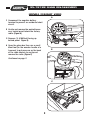
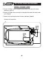
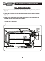
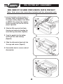
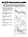
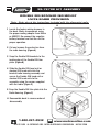
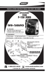
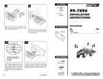
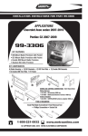
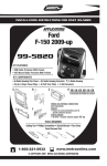
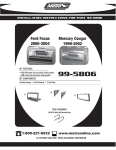
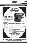
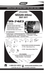
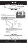
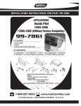
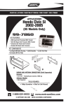
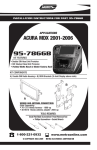
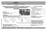
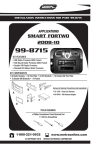
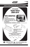
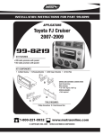
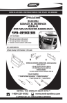
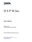
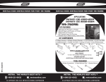
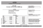
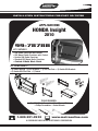
INSTALLATION INSTRUCTIONS FOR PART 99-7878B
APPLICATIONS
HONDA Insight
2010
99-7878B
KIT FEATURES
• DIN Radio Provision with Pocket
• ISO Mount Radio Provision with Pocket
• Double DIN Radio Provision
• Stacked ISO Mount Units Provision
• Painted A Matte Black Finish
KIT COMPONENTS
• A) Radio Housing • B) ISO Brackets • C) ISO Trim Plate • D) Double DIN Brackets
• E) Double DIN Trim Plate • F) Pocket
A
D
C
B
E
F
TOOLS REQUIRED:
Small Flat Blade Screwdriver/ Panel Removal Tool
• Phillips Screwdriver • Socket Wrench
1-800-221-0932
www.metraonline.com
© COPYRIGHT 2009 METRA ELECTRONICS CORPORATION
99-7878B
TABLE OF CONTENTS
Dash Disassembly
- Honda Insight 2010 . . . . . . . . . . . . . . . . . . . . . . . . . . . . . . . . .1,2
Kit Assembly
- Kit Preparation . . . . . . . . . . . . . . . . . . . . . . . . . . . . . . . . . . . . . . . . . . 3
- DIN Mount Radio Provision with Pocket . . . . . . . . . . . . . . . . . . . . . . . .4
- ISO Mount Radio Provision with Pocket. . . . . . . . . . . . . . . . . . . . . . . . 5
- Double DIN /Stacked ISO Mount Units Radio Provision . . . . . . . . . . . . .6
Note:
Refer also to the instructions included with the aftermarket radio.
KNOWLEDGE IS POWER
Enhance your installation and fabrication skills
by enrolling in the most recognized and respected
mobile electronics school in our industry.
Log onto www.installerinstitute.com
or call 800-354-6782 for more information
and take steps toward a better tomorrow.
95-7878B DASH DISASSEMBLY
HONDA INSIGHT 2010
A
1 Disconnect the negative battery
terminal to prevent an accidental short
circuit.
AUTO
2 Unclip and remove the pocket/accessory socket panel below the factory
radio. (Figure A)
FRONT
PUSH
REAR
OFF
3 Remove (1) 8 MM bolt facing up
behind panel. Figure B)
POWER
OUTLET
4 Open the glove box then use a small
blunt tool (ie: the wooden handle of a
hammer) to put pressure on the back
of the radio chassis to unclip and
remove the radio. (Figure C)
B
TO
AU USH
P
FRONT
REAR
OFF
Continued on page 2.
C
1
95-7878B DASH DISASSEMBLY
HONDA INSIGHT 2010
5 Remove (2) Phillips screws securing the hazard switch to the back of the factory
radio panel. (Figure D)
6 Remove (2) Phillips screws securing the air bag light to the back of the factory radio
panel. (Figure D)
7 Remove the (8) retaining clips from the factory radio panel. (Figure D)
Continue to kit preparartion.
D
8 RETAINING CLIPS
HAZARD
SWITCH
TWO
SCREWS
AIR BAG
SWITCH
TWO
SCREWS
2
99-7878B KIT PREPARATION
KIT PREPARATION
1 Secure the hazard switch into the radio housing panel using the factory hardware.
(Figure A)
2 Secure the air bag light into the radio housing panel using the factory hardware.
(Figure A)
3 Attach the (8) retaining clips to the radio housing panel in the same location as
removed from the factory radio panel. (Figure A)
Continue to kit assembly.
A
8 RETAINING CLIPS
HAZARD
SWITCH
TWO
SCREWS
AIR BAG
SWITCH
TWO
SCREWS
3
99-7878B KIT ASSEMBLY
DIN MOUNT RADIO PROVISION WITH POCKET
*Note: Refer also to the instructions included with the aftermarket radio.
A
1 Locate the factory wiring harness in
the dash. Metra recommends using
the proper mating adapter from Metra
or AXXESS. Re-connect the negative
battery terminal and test the unit for
proper operation.
2 Slide the DIN cage into the Radio
Housing and secure by bending the
metal locking tabs down. (Figure A)
3 Snap the pocket into the bottom
opening of the radio housing.
(Figure B)
B
4 Slide the aftermarket head unit into
the cage and secure. (Figure C)
5 Reassemble dash in reverse order of
disassembly.
C
4
99-7878B KIT ASSEMBLY
ISO MOUNT RADIO PROVISION WITH POCKET
*Note: Refer also to the instructions included with the aftermarket radio.
A
1 Locate the factory wiring harness in
the dash. Metra recommends using
the proper mating adapter from Metra
or AXXESS. Re-connect the negative
battery terminal and test the unit for
proper operation.
2 Mount the ISO Brackets to the head
unit with the screws supplied with
the unit. (Figure A)
3 Snap the pocket into the bottom
opening of the radio housing.
(Figure B)
B
4 Slide the head unit into the radio
opening until the side clips engage.
(Figure C)
5 Snap the Trim plate into the Radio
Housing. (Figure C)
6 Reassemble dash in reverse order of
disassembly.
C
5
99-7878B KIT ASSEMBLY
DOUBLE DIN/STACKED ISO MOUNT
UNITS RADIO PROVISION
*Note: Refer also to the instructions included with the aftermarket radio.
A
1 Locate the factory wiring harness in
the dash. Metra recommends using
the proper mating adapter from Metra
or AXXESS. Re-connect the negative
battery terminal and test the unit for
proper operation.
2 Cut and remove the center bar from
the radio housing. (Figure A)
3 Snap the Double DIN brackets to the
inside edge of the Double DIN trim
plate. (Figure B)
B
4 Slide the Double DIN head unit or
stacked ISO head units into the
bracket/radio housing assembly and
secure the Double DIN head unit or
stacked ISO head units to the
assembly using the screws supplied
with the radio. (Figure C)
5 Snap the Double DIN trim plate into the
Radio Housing. (Figure C)
C
6 Reassemble dash in reverse order of
disassembly.
1-800-221-0932
www.metraonline.com
REV. 07/15/09 © COPYRIGHT 2009 METRA ELECTRONICS CORPORATION INST99-7878B