1
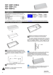
(3)- (MAYTAG)
FRONT LOAD WASHER MACHINE
CONTROL
BOARD KIT #12001454_ AND #12001725.
Se ,ce
Yr IG
Instruction
Sheet
16008915
2707490-0200
This instruction
REPAIR
PART
NO.
DESCRIPTION:
II
sheet is to be used with :
12001454,
12001725
Machine Control Board Kit
:
II II
II
This kit contains:
22002988
Machine
Control
22002335
Jumper
Wire
22002281
Pilot Lamp
Board
(Red Wire
(Yellow
No. 3)
16002292
Schematic
16008915
Instruction
Sheet
based)
I
I
The following
are servicing.
chart will depict which components
Model Number
Prior to Series 17
Series 17 & Later
MAH300OAWA
A
B
MAI_000AWQ
A
B
MAH3000A_
A
B
i
apply to the washer you
84.iDE BOARD - LEFT
= Use all components and follow instruction steps 1 - 11 below.
B = Use only the 22002988 board and follow instruction steps 1,2, 9, 10 & 11 below.
Procedure:
1.unplug the washer.
Z Remove the three screws securing the rear
console cover plate to the console and lay
the console forward carefully onto a sen,ice
blanket on the top cover.
3. Locate the ON Lightin the console and remove
the Black No. 3 wireand theWhite ,'Jo. 11
wire from the signal lamp assembly. Unsnap and
discard the ON Light lamp assembly.
4. Fold the Black No. 3 wire back and tape the wire
to the main harness out of the way.
5. Locate and remove connector P7 from the left
side of the Machine Control board.
6. Insert the jumper wire (Red Wire No. 3), found in
the service repair assembly, into position
number 5 of the P7 connector, then reconnect the
P7 connector beck onto the Machine
Control Board.
7. Remove the Yellow based indicator lamp found in
the service assembly and position the
lamp where the previous ON Light lamp assembly was previously removed. Then snap the new
lamp assembly into the console.
8, Connect the White No. 11 wire and the Red No. 3
wire to the new yellow based lamp assembly.
9, Remove the existing electrical schematic taped to
the rear wall of the console and replace
with the electdcal schematic found in the service
assembly.
lO,Reposition the console into the updght position
on the topcover and secure the three
screws fastening the console to the rear console
cover plate.
11.Replacement
is complete.