1
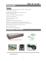
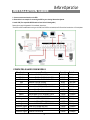
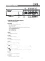
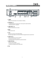
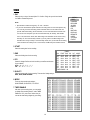
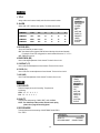
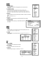
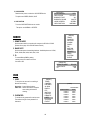
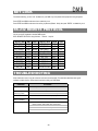
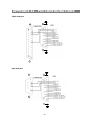
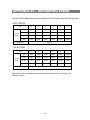
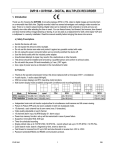
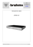
4 CH Digital Multiplex Recorder
User Manual
Please read this instructions thoroughly before operation and keep the manual in a safe
place for further reference.
773 V 0.9
DMR
WARNING
All the safety and operating instructions should be read before operation. The improper operation may cause
permanent damage.
• Please use the provided adaptor (Other adaptor is not suitable for this machine).
• Please lift and place this equipment gently.
• Do not expose this equipment to open sunlight.
• Do not use this equipment near water or in contact with water.
• Do not spill liquid of any kind on the equipment.
• Please power down the unit before unplugging.
• Do not switch the Power On & Off within short period of time (within 3 seconds).
• Do not attempt to service this equipment by yourself.
• Installation should be made by qualified service personnel.
The lightning flash with arrowhead symbol, within an equilateral triangle, is intended to alert
the user to the presence of uninsulated "dangerous voltage" within the product's enclosure that
may be of sufficient magnitude to constitute a risk of electric shock to persons.
The exclamation point within an equilateral triangle is intended to alert the user to the presence
of important operating and maintenance-(servicing) instructions in the literature accompanying
the appliance.
1
TABLE OF CONTENTS
What do you get ?
DMR
• FEATURES ---------------------------------------------------------------- ------------------------ 3
• PACKAGE CONTENT ---------------------------------------------------------------- ----------
3
Before Operation
• INSTALLATION GUIDE ---------------------------------------------------------------- --------
4
• FRONT PANEL ---------------------------------------------------------------- -------------------
5
• BACK PANEL ---------------------------------------------------------------- ---------------------
7
Basic Operation
• START THIS UNIT ---------------------------------------------------------------- ---------------- 8
• OPERATION ---------------------------------------------------------------- ------------------------ 8
Detailed Menu Setup
• ACCESS MENU ---------------------------------------------------------------- ------------------
10
• MAIN MENU ---------------------------------------------------------------- -----------------------
10
• MENU OPTIONS ---------------------------------------------------------------- -----------------
11
• MOTION DETECTION ---------------------------------------------------------------- ----------
14
Advanced Operation
• OPERATION OPTIONS ---------------------------------------------------------------- -------- 16
• KEY LOCK ---------------------------------------------------------------- ------------------------ 17
• RS-232 PROTOCOL ---------------------------------------------------------------- ------------ 17
Trouble Shooting ---------------------------------------------------------------- ------------------
17
Specifications ---------------------------------------------------------------- ----------------------
18
APPENDIX #1 – INSTALLING THE HDD ----------------------------------------------------
19
APPENDIX #2 – PIN CONFIGURATIONS ---------------------------------------------------
21
APPENDIX #3 – RACK MOUNT ----------------------------------------------------------------
23
APPENDIX #4 – RECORDING SPEED -------------------------------------------------------
24
2
What do you get ?
FEATURES
DVR Features
l Wavelet compression format replaces Time-Lapse VCR + Multiplexer / Quad
l 4 audio inputs / 2 audio outputs
l On Screen Display and Remote Control via Video Server & PC
l Picture-in-picture (PIP) in live
l Motion detection & motion trigger recording function
l Alarm input & output function
l Video loss detected on each channel
l Linear Zoom (2x~4x)
l Multiplexer & Quad recording mode switching
l Recording rate up to full size 30 images/sec. or Quad size 120 images/sec.
l Support 1 removable HDD with hot-swap capability, IDE TYPE (over 250 GB)
l Quick multiple search by date/time, alarm, full, motion list
l Security password protection
l RS-232, RS-485 communication protocol
PACKAGE CONTENT
Digital Multiplex Recorder(with HDD cartridge)
Accessories pack
User Manual
2 Keys for Cartridge
Power Adapter and Cord
NOTE : Please check the package to make sure that you receive the complete accessories which includes the
components shown above.
3
INSTALLATION GUIDE
Before Operation
1. Connect cameras and monitor to the DVR.
2. Shown below is an example of connecting the DVR to your existing Observation System.
3. Install HDD (The compatible HDD Brands are listed in the following table.)
Please refer to page.22 Appendix #1 for installation instructions.
*The HDD must be installed before turning on the DMR, but if HDD is not installed, the DVR would be functioned as 4 CH multiplexer.
COMPATIBLE HARD DISK MODELS
Manufacturer
Model
Capacity
Rotation
HITACHI
HITACHI
HITACHI
Deskstar 180 GXP (120 GB)
Deskstar 7K250, HDS722516VLAT20
Deskstar 7K250, HDS722525VLAT80
120GB
160GB
250GB
7200 rpm
7200rpm
7200rpm
IBM
IBM
Maxtor
Deskstar 120GXP (80GB)
Deskstar 120GXP (120GB)
DiamondMax 536DX(60GB) 4W060H4
80GB
120GB
60GB
7200 rpm
7200 rpm
5400rpm
Maxtor
Maxtor
Maxtor
Maxtor
Seagate
Seagate
DiamondMax Plus 9
DiamondMax Plus 9, Model#6Y120L
DiamondMax Plus 9, Model#6Y160L0
80GB
120GB
160GB
250GB
80GB
120GB
7200 rpm
7200 rpm
7200rpm
7200rpm
7200rpm
7200 rpm
Seagate
Barracuda 7200.7 Plus, ST3160023A
Western Digital Caviar WD1200BB-00CAA1
160GB
120GB
7200 rpm
7200rpm
Western Digital Caviar WD2000BB-00DWA0
Western Digital CaviarSE WD2500JB
200GB
250GB
7200rpm
7200rpm
MaxLine Plus Ⅱ , Model#7Y250P0
Barracuda ATA IV, ST380021A
Barracuda ATA V, ST3120023A
4
DMR
FRONT PANEL
1. REMOVABLE HDD CARTRIDGE & KEYHOLE
Please refer to page.22 Appendix #1.
2. LED LIGHT
The LED Light is ON under following condition.
• HDD : HDD status display
• HDD Full : HDD is full
• ALARM : To turn off the ALARM LED light, please refer to page.14 and set the
ALARM mode as OFF.
• TIMER : When Timer is set as Enabled
• PLAY : On Playing mode
• REC : On Recording mode
3. MENU
Press MENU to enter main menu.
4. ENTER
Press ENTER for confirmation.
5. SEARCH
Press SEARCH for searching recorded video.
6. ZOOM
Press ZOOM to enlarge the picture display.
7.
/+ Picture in Picture
Press PIP button for Picture in Picture screen, and “+ ” can be used for detail change.
8.
/-
Press “
4 channels display mode
” button for 4 channels display mode, and “ - ” can be used for detail change.
9. SLOW
To slow down the speed of playing mode.
10. POWER
Press Power to turn ON / OFF the DMR.
5
11. REC
Press REC to start recording.
12. PLAY
Press PLAY to playback recorded video.
13. PAUSE / Up
• Pause : Under DMR play mode, it can pause the action.
• UP : Under setup mode, it works as Up button.
14. STOP / Down
• STOP : Under DMR Record / Play mode, it can stop the moment action.
• DOWN : Under setup mode, it works as Down button.
15. REW / Left
• REW : Under DMR play mode, it can play video backward at different speeds. (Press REW again to adjust
speed as 1, 2, 4, 8, 16, 32 times)
• Left : Under setup mode, it works as Left button.
16. FF / Right
• FF : It can play video forward at high speed, and press FF again to adjust speed from 1, 2, 4, 8, 16, 32 times.
• Right : Under setup mode, it can work as Right button.
17. CAMERA SELECT (1-4)
Press the Camera Select (1-4) to select specified camera.
6
DMR
REAR PANEL
1. P0WER
Please use the provided power cord (The adaptor is embedded).
2. EXTERNAL I/O
• Controlled remotely by an external device or control system like Video Web Server.
• Alarm input, external I / O explanation.
3. VIDEO INPUT (1-4)
Connect to video source, such as camera.
4. MAIN
Connect to Main monitor.
5. CALL
Connect to CALL monitor. Show the Switch Display.
When alarm trigger happens, the call monitor will show the triggered channel for a period of time.
6. AUDIO IN (1-4)
Connect to audio sources, such as a microphone.
• IPS should be set to 30 (for NTSC) or 25 (for PAL)
* 4 audio inputs, but can only record one input at the same time.
7. AUDIO OUT (R/L)
Connect to monitor or speaker.
• IPS should be set to 30 (for NTSC) or 25 (for PAL)
* with 2 mono audio outputs from the same source.
8. FAN
7
Basic Operation
GETTING STARTED
Before using the DMR, please have a HDD installed ready, or it will be functioned as 4 CH multiplexer (refer to Appendix #1
for installation or removal of a HDD).
1. Connect the AC Power Cord and plug into an electrical outlet then press the power switch “ON”. The Red LED
indicator light will be ON and the DMR is in Standby mode.
2. Press the Power button. The POWER LED will turn from red to orange, and other red LED indicators will turn ON. It
takes approximately 5 to 15 seconds to boot the system with the message : “ HDD Detecting ”. Once connected, the
POWER LED will change to green color, and the Alarm LED will be ON.
3. Before operating the DMR, set the system time first. (refer to page.11).
NOTE : If the HDD is not installed correctly or not installed, the “ HDD not found” message will
appear only 3 seconds and then return to 4 CH Multiplexer display mode.
OPERATION
RECORDING
The DMR offers a variety of recording modes, such as record continuously, by scheduled time, and by events. You can
set up recording speed and resolution. You can set these options by selecting MENU / RECORD before recording, please
refer to page.13. Under the recording status, if power is off accidentally, recorded video will still be stored in the HDD.
DMR will return to original recording situation after power restores again.
On the screen, you will find the date, time, HDD recording type, the amount of available GB left in the HDD memory and
the letter “
” represents the method of recording that is occurring.
(OW : HDD Overwrite)
2002 – JAN – 01 01:02:03
● OW
NOTE : 1. When the HDD is full under O/W Recording mode, previous recorded files
will be overwritten without further warning notices.
2. If the HDD capacity is only 5 GB left, it will display “ 5 GB” on the up-right screen and shows orange
color, and it will buzz for seconds; so as in 4GB, 3GB, 2GB and 1GB. If the O/W Recording mode
(NOTE 1) is on, it won’t have the warning buzzer.
There are 4 recording modes: Alarm, Motion, Timer and Manual Record.
1. ALARM RECORDING
DMR is triggered by an alarm input.
symbol will be shown on the triggered channel.
2. MOTION TRIGGER RECORDING
Recording is triggered by motion detection.
symbol will be shown on the triggered channel.
3. TIMER RECORDING
Recording is scheduled by a Timer. It will indicate by the symbol
.
4. MANUAL RECORDING
Recording is initiated manually by pressing the REC button. Symbol
8
will be shown.
PLAY BACK
Press “ PLAY ” button, the DMR will show the last recording.
1. FAST FORWARD (F.F.) & FAST REWIND (F.R.)
You can increase the speeds of Fast Forward and Rewind on the DMR.
In the Play mode, press ” ► ” once to get 2X speed forward and press twice to get 4X speed,… and the maximum
speed can reach 32X.
Press ”◄ ” once to get 1X speed rewind and press twice to get 2X speed, … and the maximum speed can reach
32X.
2. SLOW FORWARD (S.F.) & SLOW REWIND (S.R.)
You can also slow down the speeds of Forward and Rewind on the DMR.
In the Play mode, press the SLOW button and you will enter Slow mode.
Press ” SLOW ” once to get 1/2X speed forward and press ” ► ” to get 1/4X speed,… and the slowest speed can
reach
1/32X.
Press ”◄ ” once to get 1/2X speed rewind and press twice to get 1/4X speed, … and the slowest speed can reach
1/32X.
3. PAUSE
It will let you pause the current image displayed on the screen.
4. STOP
Press “ STOP ” under any circumstance, DMR will return to live monitoring mode.
5. IMAGE JOG DIAL
It will allow you to manually view video frame-by-frame, one image at a time.
While in PLAY mode, press “ PAUSE ”, it will pause the screen.
Pressing “ ► ” button advances the frozen screen one image forward.
Pressing “ ◄ ” button moves back one image.
CAMERA SELECT (1-4)
Press Camera Select (1-4) to select appointed camera to display on full screen mode.
9
Detailed Menu Setup
MAIN MENU
There are 12 options available in the Main Menu:
(MENU)
TIMER
CAMERA
RECORD
ALARM
DWELL
PIP
MOTION
DISPLAY
REMOTE
USER
SYSTEM
EVENT
TIMER ---------- Programs Specific Time to Record
CAMERA ------- Camera Channel Setup
RECORD ------- Record Mode Setup
ALARM --------- Alarm Setup
DWELL --------- Dwell time Setup
PIP --------------- Picture in Picture Setup
MOTION -------- Motion Detection Setup
DISPLAY ------- Display Mode Setup
REMOTE ------- Remote Control Setup
USER ----------- User Password Setup
SYSTEM ------- System Setup
EVENT --------- Event List
Outlined below are the buttons used for Menu setting :
•
•
•
•
•
“ Up” and “ Down” : Scroll up and down or change values when an option is selected and is blinking
“ Left” and “ Right” : Scroll sideways within a menu option that has been selected
“ + ” and “ - ” : Increase and decrease the number or change values when an option is selected and is blinking
ENTER : Selects a submenu / an option under a submenu for browsing / modification
MENU : Completes modification of a menu option; exits a menu
10
DMR
MENU OPTIONS
SYSTEM
1. AUDIO INPUT
To choose one of 4 channels to record. ( It can only record 1 input)
2. BUZZER
Set the BUZZER “ON”, it will buzzer by event occurrence when the setting is ON.
3. EXT ALARM
To set the EXTERNAL AUDIBLE ALARM. It will be trigged by event occurrence
when the setting is ON.
4. VLOSS ALARM
To set the VLOSS ALARM. When the setting is “ON”, the alarm will occurrence by the setting
of Buzzer, EXT alarm or Alarm Duration.
(MENU)
TIMER
CAMERA
RECORD
ALARM
DWELL
PIP
MOTION
DISPLAY
REMOTE
USER
SYSTEM
EVENT
5. MOTION ALARM
To set the MOTION AUDIBLE ALARM. When the setting is “ON”, the alarm will occurrence
by the setting of Buzzer, EXT alarm or Alarm Duration.
6. HDD OVERWRITE
To set the HDD OVERWRITE. When the HDD is full under O/W recording mode, previous recorded files
will be overwritten without further warning notices when the HDD OVERWRITE is ON.
7. MESSAGE LATCH
To select whether the DMR messages will disappear after 10
second or remain on screen. NO is the default setting which the
messages will disappear after 10 sec.
NOTE : Video loss, Alarm and Motion messages will be shown
the same as Alarm Duration time.
8. DATE DISPLAY
To set the date Y/M/D, M/D/Y, D/M/Y and OFF on monitor or not.
9. DATE
To set the date shown on the DMR.
(SYSTEM)
AUDIO INPUT
1
BUZZER
ON
EXT ALARM
ON
VLOSS ALARM
ON
MOTION ALARM
ON
HDD OVERWRITE
YES
MESSAGE LATCH
YES
DATE DISPLAY
D/M/Y
DATE
26-DEC-2003 [FRI]
TIME
22:55:34
CLEAR HDD
YES
SYSTEM RESET
YES
10. TIME
To set the time on the DMR.
11. CLEAR HDD
Delete all the contents of the HDD. When you choose “YES” on this option, press “ENTER” and you
will be prompted with the question shown: Press “→ ” to clear HDD or press ”← ” to cancel.
12. SYSTEM RESET
Reset all system settings back to factory default settings.
11
TIMER
1. DAY
Select the day, or days of the week (Mon–Fri / Sat-Sun / Daily) that you wish to schedule
the DMR to automatically record.
NOTE :
1. Special Date could be changed by “ +” and “ -” buttons.
2. If you have selected the specific date and recording timer set from that specific day
to a new day, then the Recording Timer Schedule will be set as whole week. For
specific date of Recording Timer Schedule, it is not recommended to set End Time
over 23:59. For example:If you set Timer Schedule Day as Sunday, and START
from 11:30, but End on 00:20, then Recording Timer Schedule is set as from every
Sunday's 11:30 to next Sunday‘s 00:20. If you only want to set Recording Timer
Schedule from every Sunday 11:30 to Monday 00:20, then you should set Recording
(MENU)
TIMER
CAMERA
RECORD
ALARM
DWELL
PIP
MOTION
DISPLAY
REMOTE
USER
SYSTEM
EVENT
Timer Schedule as Sunday from 11:30 to 23:59, and Monday from 00:00 to 00:20.
2. START
Select the starting time for the recording.
3. END
Select the finishing time for the recording.
4. IPS
Stands for Images Per Second and it could let you see Record submenu
for more details.
NTSC- 30、 15、 8、 4、 2、 1
PAL- 25、 12、 6、 3、 2、 1
5. QUALITY
Select the image quality for the recording. There are four Quality settings :
BEST, HIGH, NORM and BASE.
6. MODE
There are three record mode settings :
QUAD-FRAME, QUAD-FIELD, FULL-FIELD.
7. TIMER ENABLE
After sets up the recording timer, you can enable
or disable timer recording function., when TIMER
ENABLE is “ON”, press “menu” button then you
can see the timer setting diagram by your setting.
12
(TIMER)
DAY START END IPS
DAILY 01:00 22:00 30
OFF 00:00 00:00 30
OFF 00:00 00:00 30
OFF 00:00 00:00 30
OFF 00:00 00:00 30
OFF 00:00 00:00 30
OFF 00:00 00:00 30
OFF 00:00 00:00 30
TIMER ENABLE : ON
QLT MODE
BEST Q-FR
BEST Q-FI
BEST Q-FI
BEST Q-FR
BEST Q-FR
BEST Q-FR
BEST Q-FI
BEST Q-FI
CAMERA
1. TITLE
(MENU)
TIMER
CAMERA
RECORD
ALARM
DWELL
PIP
MOTION
DISPLAY
REMOTE
USER
SYSTEM
EVENT
Assign a title to each camera. Initially each title is the camera’s number.
2. ALARM
Select LOW / OFF / HIGH for alarm polarity. The default value is LOW.
TITLE
ALARM
REC
BR
CT
CL
HUE
CAMERA 1
LOW
ON
18
15
15
18
CAMERA 2
OFF
OFF
18
15
15
18
CAMERA 3
HIGH
OFF
18
15
15
18
CAMERA 4
HIGH
ON
18
15
15
18
3. RECORD (REC)
Set up which channel you want to record.
ON : when alarm input is triggered, DMR will record alarming channel more frequently.
For example : when CH01 is triggered, the record method will become 1-2-1-3-1-4… .
OFF : DMR will not record.
4. BRIGHTNESS (BR)
Have a video bright adjustment of each channel. The level is from 0 to 63.
5. CONTRAST (CT)
Have a video contrast adjustment of each channel. The level is from 0 to 63.
6. COLOR (CL)
Have a video color contrast adjustment of each channel. The level is from 0 to 63.
7. HUE (HUE)
Have a video hue adjustment of each channel. The level is from 0 to 63.
RECORD
1. RECORD IPS
Select the images per second of recording. The options are
as following :
NTSC- 30、 15、 8、 4、 2、 1
PAL- 25、 12、 6、 3、 2、 1
2. QUALITY
There are four quality settings : BASIC, BEST, HIGH, NORMAL.
NOTE : The relationship of Record time, IPS and record quality,
please refer to page.26 Recording Speed.
(MENU)
TIMER
CAMERA
RECORD
ALARM
DWELL
PIP
MOTION
DISPLAY
REMOTE
USER
SYSTEM
EVENT
3. RECORD MODE
There are three record mode settings : QUAD-FRAME, QUAD-FIELD,
FULL-FIELD.
(RECORD)
RECORD IPS
QUALITY
RECORD MODE
13
30
NORMAL
QUAD-FRAME
ALARM
1. ALARM ENABLE
To set the ALARM ENABLE. It will be triggered by event occurrence when the
setting is ON.
2. ALARM DURATION
Set the reaction time which was determined by how long the alarm mode
responded to a buzzer. Default setting is 10 sec. Options are 10 SEC, 15 SEC, 20
SEC, 30 SEC, 1 MIN, 2 MIN, 3 MIN, 5 MIN, 10 MIN, 15 MIN, 30 MIN, ALWAYS, AUTO.
3. REC IPS
Select the images per second of recording during an ALARM. The options are as following:
NTSC- 30、 15、 8、 4、 2、 1
PAL- 25、 12、 6、 3、 2、 1
(MENU)
TIMER
CAMERA
RECORD
ALARM
DWELL
PIP
MOTION
DISPLAY
REMOTE
USER
SYSTEM
EVENT
4. QUALITY
There are four quality settings during an ALARM : BASE, BEST, HIGH, NORM.
5. RECORD MODE
There are three record mode settings : QUAD-FRAME, QUAD-FIELD,
FULL-FIELD.
(ALARM)
ALARM ENABLE
YES
ALARM DURATION
15 MIN
RECORD IPS
30
QUALITY
NORMAL
RECORD MODE
QUAD-FRAME
DWELL
1. NORM
To set up the DWELL time period that each channel auto sequentially shows on call
monitor. The level is from 1 to 15 SEC or OFF.
2. ALARM
To set up the DWELL time period when alarm input is triggered. The level is from 1 to
15 SEC or OFF.
(DWELL)
NORM ALARM
CAM1
01
01
CAM2
01
01
CAM3
01
01
CAM4
01
01
(MENU)
TIMER
CAMERA
RECORD
ALARM
DWELL
PIP
MOTION
DISPLAY
REMOTE
USER
SYSTEM
EVENT
PIP
1. FULL SCREEN
To set up the full screen background picture display.
2. PIP SCREEN
To set up the picture with a 1/9 size screen “insert”.
3. POSITION
There are six position settings : D/L, D/M, D/R, U/L, U/M, U/R.
(PIP)
FULL SCREEN
PIP SCREEN
POSITION
14
CAM 1
CAM 2
D/R
(MENU)
TIMER
CAMERA
RECORD
ALARM
DWELL
PIP
MOTION
DISPLAY
REMOTE
USER
SYSTEM
EVENT
MOTION
1. SEN (Sensitivity)
Sets the sensitivity of the Pixel-based Motion Detection feature from 1fo 70.
2. MD-NVM
Sets the number of targets in which Motion must occur in order to trigger an Alarm
(from 1-99 target areas).
Note: MD-NVM cannot be less than the number of targets set in the AREA.
3. RE
Sets the Reference image to which the current screen is compared (from 1-99).
For example, the value 64 would compare the current image to the 64th previous
screen image.
(MENU)
TIMER
CAMERA
RECORD
ALARM
DWELL
PIP
MOTION
DISPLAY
REMOTE
USER
SYSTEM
EVENT
4. DET
The motion detection on each channel setup can be turned to
ON or OFF individually.
5. AREA
Press the ENTER button on this option to set the Pixel-based
Motion Detection Area for each channel. Green targets
represent the Motion Detection Area(Figure 1-2), and Purple
targets represent motion currently taking place (Figure 1-3).
To modify the Motion Detection Area, use the following controls:
CAM1
CAM2
CAM3
CAM4
SEN
70
70
70
70
(MOTION)
MD-NVM RE DET
03
64 ON
03
64 OFF
03
64 ON
03
64 ON
AREA
AREA
AREA
AREA
MOTION RECORD : ON
DAY
START
END
DAILY 00 : 00
00 : 00
+ : turns the selected target ON/OFF.
▲ ▼ ◄ ► : navigates between targets
- :turns all targets on the screen ON/OFF
Zoom: turns all targets in the selected row ON/OFF
6. MOTION RECORD
When the DET setting is “ON”, you can set up the MOTION RECORD function,
1. Select “ON” to set up the motion trigger record: It can automatically switch to Record Mode. The motion detection will
change the scanning sequence and shows
on the monitor.
NOTE: The trigger recording time will depend on ALARM DURATION mode setting (Please refer to page.11 for ALARM DURATION) and it will
record from the last trigger time. For example, when the alarm duration setting is 1 min, the recording time is from 9:00:00 to 9:01:00. If the
motion detection trigged again at 9:00:40, the trigged recording time will from 9:00:00 to 9:00:40 and 9:00:40 to 9:01:40. The total
recording time is 00:01:40.
2. Select ”OFF”: The screen still shows
and if it is in record mode, the motion detection will change the scanning
sequence.
For example : If the motion is detected on Camera #1, its recording & scanning sequence will be more frequently. The sequence
will be as 1st, 2nd, 1st, 3rd, 1st, … 4th. And channel 1 will show
on the screen. If 2nd camera and 3rd camera
both motion detection are activated, they will be scanning as 2st, 3rd, 1st, 2nd, 3rd, 4th, 2nd, 3rd, 1st, 2nd, 3rd,
4th … and vice versa. And CH2 & CH3 will show
for a period of time which is same as Alarm Duration time.
15
7. DAY / START / END
To setup the DAY and the START/ END time for motion trigger recording timer setting.
Figure 1-1
Figure 1-2
MOTION DETECTION SETUP
MOTION DETECTION SETTING — ROW SETUP
1
2
3
4
5
6
7
8
9
1
10 11 12 13 14 15 16
2
3
4
5
6
7
8
9
10 11 12 13 14 15 16
1
2
3
4
5
6
7
8
9
11
12
1
2
3
4
5
6
7
8
9
11
12
Figure 1-3
Figure 1-4
MOTION DETECTION TRIGGERED-TURN INTO PURPLE
BACK TO MOTION DETECTION SETTING
1
2
3
4
5
6
7
8
9
1
10 11 12 13 14 15 16
1
2
3
4
5
6
7
8
9
11
12
2
3
4
5
6
7
8
9
10 11 12 13 14 15 16
1
2
3
4
5
6
7
8
9
11
12
DISPLAY
1. TITLE DISPLAY
To set the title shown on monitor or not.
2. OSD COLOR
Select the OSD (On screen display) color. The options are
YELLOW, WHITE, GREEN, BLACK, BLUE, RED, PINK, CYAN.
3. BORDER TYPE
To set the BORDER TYPE on screen display.
The options are 8/4, 4/2, 2/1 or OFF.
4. BORDER COLOR
Select the BORDER COLOR. The options are
YELLOW, WHITE, GREEN, BLACK, BLUE, RED, PINK, CYAN.
16
(MENU)
TIMER
CAMERA
RECORD
ALARM
DWELL
PIP
MOTION
DISPLAY
REMOTE
USER
SYSTEM
EVENT
5. LOSS SCREEN
Retain the last picture or select the LOSS SCREEN color.
The options are GREEN, BLACK, BLUE.
6. OSD POSITION
To set the OSD POSITION shown on monitor.
(DISPLAY)
TITLE DISPLAY
OSD COLOR
BORDER TYPE
BORDER COLOR
LOSS SCREEN
OSD POSITION
YES
YELLOW
4/2
WHITE
GREEN
NORMAL
The options are NORMAL or CENTER.
REMOTE
1. REMOTE MODE
Set the remote mode for connection with computer via RS-232 or RS-485.
(Please refer to page. 23 for RS-232 Remote Control).
2. BAUD RATE
Set the remote protocol transmitting baud rate. Available options are 115200,
57600, 19200, 9600, 4800, 3600, 2400, 1200.
3. ID
To control different DMR by setting
remote protocol. ID number can be set
from 000 to 255.
(MENU)
TIMER
CAMERA
RECORD
ALARM
DWELL
PIP
MOTION
DISPLAY
REMOTE
USER
SYSTEM
EVENT
(REMOTE)
REMOTE MODE
BAUD RATE
ID
RS-485
9600
255
USER
1. USER
To set up the user account for controlling. It
allows 8 users setting.
Supervisor – Control all the functions.
Other User – Review all functions except the
menu setting and event list
cleaning.
2. PASSWORD
To set the security password for each account.
The maximum length of user password is 4
characters.
(MENU)
TIMER
CAMERA
RECORD
ALARM
DWELL
PIP
MOTION
DISPLAY
REMOTE
USER
SYSTEM
EVENT
18
(USER)
PASSWORD
SUPERVISOR
USER 1
USER 2
USER 3
USER 4
USER 5
USER 6
USER 7
0000
0000
0000
0000
0000
0000
0000
0000
EVENT
A single page can display 16 recorded events. Press “◄ ” or “► ” to change the
pages or press ▲ + ▼ to CLEAR the EVENT record.
DISK FULL: HDD is full
PWR REST : Power restored
M-HD REMS: HDD remove
M-HD REPL: HDD replace
M-HD ERR : HDD error
M-HD WARM: HDD warning
K UNLOCKS: Key is unlock
(MENU)
TIMER
CAMERA
RECORD
ALARM
DWELL
PIP
MOTION
DISPLAY
REMOTE
USER
SYSTEM
EVENT
DMA ERROR: DMA error
C1 VLOSS : Camera 1 is video loss
C2 ALARM : Camera 2 has been triggered by external I/O alarm
C3 MOTION: Camera 3 has been triggered by motion detection
SYSTEM ERROR: System might fail
CAM 2 VLOSS: Channel: 2 Video loss
CAM 3 ALARM: Channel: 3 External I/O Alarm have triggered
POWER RESTORE : Power restored
17
C1 VLOSS
C2 ALARM
K UNLOCKS
M-HD ERR
M-HD WARM
PWR REST
PMA ERROR
M-HD REPL
↑
26-DEC-2002 03:00:00
26-DEC-2002 03:00:00
26-DEC-2002 03:00:00
26-DEC-2002 03:00:00
26-DEC-2002 03:00:00
26-DEC-2002 03:00:00
26-DEC-2002 03:00:00
26-DEC-2002 03:00:00
+↓ : CLEAN
OPERATION OPTIONS
Advanced Operation
ZOOM
Press ZOOM button to enlarge the display of main picture. It displays zoomed picture on main picture and a
small window inserted. The inserted window contains a movable 1/4 view size of the appointed camera. The
range is from 2X to 4X.
•Press PIP : Zoom in
•Press QUAD : Zoom out
•Press the “Zoom” button again to leave the zoom pointer.
•Press Camera (1-4) to select channel.
•Press ▲ ▼ ◄ ► to move the zoom position.
VIDEO LOSS
Screen will display ‘LOSS” in the center of display picture, if the video input is not connected properly.
SEARCH
1. LAST RECORD
LAST RECORD
FULL LIST
ALARM LIST
MOTION LIST
TIME SEARCH
Play the last recorded piece of video.
2. FULL LIST
List all recorded video on the HDD which sorted by time.
: Motion Recording
: Manual Recording
: Alarm Recording
: Timer Recording
M : Storage in Master HDD
S : Storage in Slave HDD
2003-JAN-01 01:02:03 M
2003-JAN-05 05:02:03 M
2003-MAR-12 04:02:03 M
2003-APR-02 03:02:04 M
2003-MAY-01 05:02:03 M
2003-AUG-09 01:02:01 M
← : PAGE UP → : PAGE DOWN
NOTE: It will display different color on each record list
mention above.
3. ALARM LIST
List all recorded video triggered by an Alarm.
NOTE : If there are no Alarm in the record, the screen will
display “EMPTY”.
4. MOTION LIST
List all motion triggered records.
5. TIME SEARCH
Find video recorded on a specific date that is entered.
19
DMR
KEY LOCK
For advanced security, you can “Lock” the buttons on your DMR. Key-Lock prevents other people from using the system.
Press ENTER and MENU at the same time to enable Key Lock.
Press ENTER and MENU at the same time and key in password (Default : 0000), then press “ENTER“ to disable Key Lock.
RS-232 REMOTE PROTOCOL
You can use the PC keyboard to simulate DMR keypad.
DATA: REMOTE PROTOCOL using 8 bit data、 1 start bit、 1stop bit
F UNCT ION CODE AS CII FUNCT ION CODE AS CII
KEY_MENU
KEY_SEARCH
KEY_ENTER
KEY_QUAD
KEY_ZOOM
KEY_PIP
KEY_SLOW
KEY_REC
KEY_LEFT
KEY_UP
0x4D
0x73
0x0D
0x51
0x5A
0x70
0x53
0x72
0x4C
0x55
M
KEY_PLAY
s
KEY_DOWN
ENTER
KEY_RIGHT
Q
KEY_POWER
Z
KEY_KEY_LOCK
p
KEY_CH1
S
KEY_CH2
r
KEY_CH3
L
KEY_CH4
TINER REC PROCEED
U
0x50
0x4E
0x52
0x57
0x4B
0x31
0x32
0x33
0x34
0X54
P
N
R
W
K
1
2
3
4
T
TROUBLESHOOTING
When malfunction occurs, it may be not serious and can be corrected easily. The table below describes some typical
problems and their solutions. Please check them before calling your DMR dealer.
PROBLEM
No power
l
SOLUTION
Check power cord connections.
l
Confirm that there is power at the outlet.
Not working when
press any button
l
l
Check if it is under Key Lock mode.
Press "MENU" & "ENTER" to exist Key Lock mode.
No recorded video
l
Check if the HDD is installed properly.
Timer Record enable
does not working
No live video
l
Check if the Record Enable is set to YES
l
Check camera video cable and connections.
l
Check monitor video cable and connections.
l
Confirm that the camera has power.
l
Check camera lens setting.
20
DMR
SPECIFICATIONS
Video format
Hard disk storage
Record mode
Camera Input Signal
Camera Loop Back
Main Monitor Output
Call Monitor Output
Audio input
NTSC/EIA or PAL/CCIR
IDE type, UDMA 66, supported 200 GB HDD
Manual / Alarm / Timer / Motion
Composite video signal 1 Vp-p 75Ω BNC, 4 channels
Composite video signal 1 Vp-p 75Ω BNC, 4 channels
Composite video signal 1 Vp-p 75Ω BNC
Composite video signal 1 Vp-p 75Ω BNC
4 audio inputs, (RCA) *
2 audio outputs, (RCA) **
16 * 12 targets per camera
Audio output
Motion Detect Area
Motion Detect Sensitivity
Video Loss Detection
Refresh Rate
Recording Rate
Dwell Time
Picture in Picture
Key Lock
Picture Zoom
Camera Title
Video Adjustable
Alarm Input
Alarm Output
Remote Control
Time Display Format
Power Source
99 Levels
Yes
Up to 240 images/sec. for NTSC / 200 images/sec. for PAL
Up to 30 images/sec. for NTSC / 25 images/sec. for PAL
Programmable (1~15 Sec)
Yes (Movable)
Yes
2*2 ~4*4 (Movable)
8 letters
Hue/ Color/ Contrast/ Brightness Adjustable
TTL input, Hi (5V), Low (GND)
COM./N.O/N.C
RS-232 or RS-485
YY/MM/DD, DD/MM/YY, MM/DD/YY, OFF
AC90~220V, 47Hz~63Hz
<32W
Power Consumption
Operation Temperature
RS-232C / RS-485 (bps)
10 ~ 40 ℃
115200 、 57600 、 19200 、 9600 、 4800 、 3600 、 2400 、 1200
Dimension (mm)
343(W) x 223(L) x 59(H)
2.05 k gs
Net Weight
•Specifications are subject to change without notice.
✻ 4 audio inputs, can select only 1 during operation for recording
✻ ✻ with 2 mono audio outputs from the same source.
21
APPENDIX #1 – INSTALLING the HDD
Follow the steps carefully in order to ensure correct installation.
The compartment located on the front panel of the DMR is the removable Cartridge, in which you insert the HDD. The various
parts of the Cartridge are labeled for your reference.
1.Remove the Cartridge from the DMR
Step 1
Remove the Cartridge from the DMR.
Step 2
Put HDD into the HDD cartridge.
Please notice the bottom side is power side
as chart shows.
2.
Step 3
Screw the HDD to the cartridge. Please be
aware that the screw hole is different from
different brands HDD.
3.
For example, for Western Digital, it is to the
right side; for IBM and Maxtor, it is to the left
side.
22
APPENDIX #2 – PIN CONFIGURATIONS
15 pin com port
•
•
DVR
•
•
9 pin com port
•
•
DVR
DQR
•
•
23
PIN 1. RS232-TX : RS-232
DQR can be controlled remotely by an external device or control system, such as a control keyboard, using RS232 serial communications signals.
PIN 2. RS232-RX : RS232
DQR can be controlled remotely by an external device or control system, such as a control keyboard, using RS232 serial communications signals.
PIN 3, 4, 5, 6 ALARM INPUT
To connect wire from ALARM INPUT (PIN 3, 4, 5, 6) to GND ( PIN 9 ) connector, DQR will start recording and
buzzer will be on. When alarm has been triggered, signal becomes “Low”, and it will stop all alarm activities.
Under normal operation, signal remains “High”.
PIN 7. EXTERNAL ALARM NC
Under normal operation COM connect with NC and disconnect with NO. But when alarm triggered, COM
disconnect with NC, and connect with NO.
PIN 8. EXTERNAL ALARM NO
Under normal operation, COM will disconnect from NO. But when Alarm triggered, COM will connect with NO.
PIN 9. GND
GROUND
PIN 10. RS485-B
DQR can be controlled remotely by an external device or control system, such as a control keyboard, using
RS485 serial communications signals.
PIN 11. RS485-A
DQR can be controlled remotely by an external device or control system, such as a control keyboard, using
RS485 serial communications signals.
PIN 12. DISK FULL (OUTPUT)
When HDD is full, it sends a signal to trigger next DQR record mode, if you install another DQR. Under normal
operation, the signal remains “High”. But when disk full, DQR will send the “Low” signal.
PIN 14. ALARM RESET (INPUT)
To connect wire from ALARM RESET ( PIN 14 ) to GND ( PIN 9 ) connector, it can disable ALARM. An external
signal to ALARM RESET ( PIN 14 ) can be used to reset both ALARM OUTPUT signal and DQR’s internal buzzer.
When alarm has been triggered, signal becomes “Low”, and it will stop all alarm activities. Under normal operation,
signal remains “High”.
PIN 15. EXTERNAL ALARM COM
Under normal operation COM connect with NC and disconnect with NO. But when alarm
triggered, COM disconnect with NC, and connect with NO.
24
APPENDIX #4 – RECORDING SPEED
The Record Time is different based on Record Speed and Record Quality. Please refer to following table.
NTSC SYSTEM
IPS
Record
Quality
30
15
8
4
2
1
Best
48hr
96hr
180hr
360hr
750hr
1440hr
High
60hr
120hr
226hr
450hr
937hr
1800hr
Normal
96hr
192hr
360hr
750hr
720hr
2880hr
Basic
160hr
320hr
600hr
1250hr
1200hr
4800hr
HDD Type
240 GB
PAL SYSTEM
IPS
Record
Quality
25
12
6
3
2
1
Best
48hr
100hr
202hr
406hr
608hr
1216hr
High
60hr
126hr
254hr
506hr
760hr
1520hr
Normal
98hr
202hr
406hr
810hr
1216hr
2440hr
Basic
162hr
336hr
676hr
1350hr
2026hr
4050hr
HDD Type
240 GB
Note: Above data is obtained from actual test of recording normal TV program. (For
Reference Only)
26