1
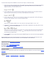
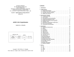
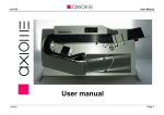
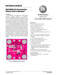
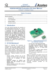
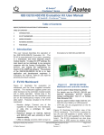
Maxim > App Notes > MICROPROCESSOR SUPERVISOR CIRCUITS
Keywords: sequencing, sequencer, monitor, reset, voltage tracking, voltage tracker
Sep 20, 2006
APPLICATION NOTE 3918
User's Guide for the MAX6877 Power-Supply Tracker/Sequencer
Abstract: This application note is a step-by-step User's Guide for designing with the MAX6877 voltage tracker and
sequencer. The note explains how to make suitable component calculations.
Figure 1. The basic circuit for the MAX6877.
MAX6877 Overview
●
●
●
●
●
Tracks or sequences up to three voltages
Closed-loop tracking control with programmable slew rate
Program thresholds with resistors
Program slew rate and timing delays with capacitors
Fault output and power-good output
Description
The MAX6877 voltage tracker/sequencer can track or sequence up to three voltages. Use the TRACK/SEQ pin to select
tracking or sequencing. The device will either track or sequence the three voltages, but it cannot track and sequence
simultaneously. Power-up begins when EN/active-low UV is asserted and all three input voltages are above their
thresholds. In the example circuit in Figure 1, EN/active-low UV is connected to the 12V bus, so the circuit will turn
on when the bus exceeds its threshold and turn off when it falls under its threshold.
To create a basic design with the MAX6877, such as the one in Figure 1, follow these steps:
1. Select the input voltage thresholds for IN1, IN2, and IN3. The input voltages must exceed these thresholds for
power-up to begin. Use the following formula to set the resistor-divider values for IN1. (For IN2 or IN3,
replace R1 with R3, or R5 and R2 with R4 or R6.)
2. Select the EN/active-low UV threshold using the following formula. EN/active-low UV can also be used as a
logic-level input to control power up. If not used, connect EN/active-low UV to ABP.
3. Set the voltage slew rate. (This is the rate at which the voltages at the outputs OUT1, OUT2, OUT3 ramp up
and down.) Select capacitor CSLEW by using the following formula:
where CSLEW is in farads, and SR is in V/s. CSLEW must be in the range of 100pF < CSLEW < 1nF.
4. In sequencing-mode only, the voltages come up one after another, separated by a time delay which is set by
capacitor CDELAY using the following formula:
where CDELAY is in farads, and tDELAY is in seconds. tDELAY is also the delay time from when all thresholds are
exceeded to the start of sequencing or tracking. CDELAY can be safely left out of the circuit, in which case
tDELAY becomes the default 200µs.
5. Pick the MOSFETs for each channel. Ensure that the MAX6877 gate-drive circuit can drive the gate capacitance
of the MOSFET.
Multiple MAX6877 parts can be connected together by connecting the power-good output of the first device to the
enable input (EN/active-low UV) of the next device. For more information, see the data sheet.
Application Note 3918: www.maxim-ic.com/an3918
More Information
For technical support: www.maxim-ic.com/support
For samples: www.maxim-ic.com/samples
Other questions and comments: www.maxim-ic.com/contact
Automatic Updates
Would you like to be automatically notified when new application notes are published in your areas of interest? Sign up
for EE-Mail.
Related Parts
MAX6877: QuickView -- Full (PDF) Data Sheet -- Free Samples
AN3918, AN 3918, APP3918, Appnote3918, Appnote 3918
Copyright © by Maxim Integrated Products
Additional legal notices: www.maxim-ic.com/legal