1
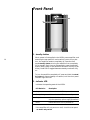
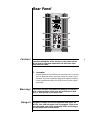
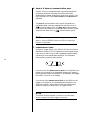
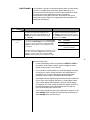
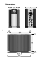
Owner’s Manual
Nº33H
Monaural
Power Amplifier
Important Safety Instructions
1. Read these instructions.
2. Keep these instructions.
3. Heed all warnings.
4. Follow all instructions.
5. Do not use this apparatus near water.
6. Clean only with a dry cloth.
7. Do not block ventilation openings. Install in accordance with the manufacturer’s instructions.
8. Do not install near any heat sources such as radiators, heat registers, stoves, or another apparatus
that produces heat.
9. Do not defeat the safety purpose of the polarized or grounding-type plug. A polarized plug has
two blades with one wider than the other. A grounding-type plug has two blades and a third
grounding prong. The wide blade or third prong is provided for safety. If the provided plug
does not fit into the outlet, consult an electrician for replacement of the obsolete outlet.
10. The MAINS cord is intended to be the safety disconnect device for this apparatus. Ready access
to the MAINS cord shall be maintained at all times.
i
11. Protect the power cord from being walked on or pinched, particularly at plugs, convenience
receptacles, or the point where it exits from the apparatus.
12. Only use attachments and accessories specified by the manufacturer.
13. Unplug this apparatus during lightning storms or when unused for long periods of time.
14. Refer all servicing to qualified service personnel. Servicing is required when the apparatus has
been damaged in any way, such as when the power cord or plug has been damaged; liquid has
been spilled or objects have fallen into the apparatus; or the apparatus has been exposed to
rain or moisture, does not operate normally, or has been dropped.
15. Ventilation should not be impeded by covering the ventilation openings with items such as
newspapers, table cloths, curtains, etc.
16. No naked flame sources, such as candles, should be placed on the apparatus.
17.
Terminals marked with this symbol may be considered HAZARDOUS LIVE and the
external wiring connected to these terminals requires installation by an INSTRUCTED
PERSON or the use of ready-made leads or cords.
Warning!
To reduce the risk of fire or electric shock, do not expose the apparatus to rain or moisture. Do
not place objects containing liquid, such as vases, on this apparatus.
FCC Notice
This equipment has been tested and found to comply with the limits for a Class B digital device,
pursuant to part 15 of the FCC Rules. These limits are designed to provide reasonable protection
against harmful interference in a residential installation. This equipment generates, uses, and can
radiate radio frequency energy and, if not installed and used in accordance with the instructions,
may cause harmful interference to radio communications. However, there is no guarantee that
interference will not occur in a particular installation. If this equipment does cause harmful
interference to radio or television reception, which can be determined by turning the equipment
off and on, the user is encouraged to try to correct the interference by one or more of the following
measures:
•
Reorient or relocate the receiving antenna.
•
Increase the separation between the equipment and the receiver.
•
Connect the equipment into an outlet on a circuit different from that to which the receiver is
connected.
•
Consult an authorized Mark Levinson dealer or an experienced radio/TV technician for help.
Caution!
Changes or modifications not expressly approved by the party responsible for compliance could
void the user’s authority to operate the equipment.
ii
Canada
This Class B digital apparatus complies with Canadian ICES-003.
Cet appareil numérique de la classe B est conforme à la norme NMB-003 du Canada.
3 Oak Park
Bedford, MA 01730-1413 USA
Telephone:
781-280-0300
Fax:
781-280-0490
www.marklevinson.com
Customer Service
Telephone:
781-280-0300
Sales Fax:
781-280-0495
Service Fax: 781-280-0499
Product Shipments
16 Progress Road
Billerica, MA 01821-5730 USA
Part No. 070-630273 | Rev 3 | 02/05
“Mark Levinson” and the Mark Levinson logo are registered trademarks
of Harman International Industries. U.S. patent numbers and other
worldwide patents issued and pending.
“Madrigal Audio Laboratories” and the Madrigal Audio Laboratories
logo are registered trademarks of Harman International Industries.
U.S. patent numbers and other worldwide patents issued and pending.
©2005 Harman Specialty Group. All rights reserved.
This document should not be construed as a commitment on the
part of Harman Specialty Group. The information it contains is
subject to change without notice. Harman Specialty Group assumes
no responsibility for errors that may appear within this document.
Documentation
Conventions
This document contains general safety, installation, and operation
instructions for the Nº33H Power Amplifier. It is important to read
this document before attempting to use these components. Pay
particular attention to safety instructions.
Appears on the component to indicate the
presence of uninsulated, dangerous voltages
inside the enclosure – voltages that may be
sufficient to constitute a risk of shock.
Appears on the component to indicate important
operation and maintenance instructions
included in the accompanying documentation.
Appears on the component to indicate
compliance with the EMC (Electromagnetic
Compatibility) and LVD (Low-voltage Directive)
standards of the European Community.
iii
Warning!
Calls attention to a procedure, practice,
condition, or the like that, if not correctly
performed or adhered to, could result in
personal injury or death.
Caution!
Calls attention to a procedure, practice,
condition, or the like that, if not correctly
performed or adhered to, could result in
damage or destruction to part or all of the
component.
Note
Calls attention to information that is essential to
highlight.
Table of Contents
Unpacking . . . . . . . . . . . . . . . . . . . . . . . . . . . . . . . . . . . . . .2
Opening the Shipping Crate . . . . . . . . . . . . . . . . . . . . . . . . . . . .2
Moving the Nº33H . . . . . . . . . . . . . . . . . . . . . . . . . . . . . . . . . . .3
Product Registration . . . . . . . . . . . . . . . . . . . . . . . . . . . . . . . . . .3
Installation Considerations . . . . . . . . . . . . . . . . . . . . . . . . . .4
Placement . . . . . . . . . . . . . . . . . . . . . . . . . . . . . . . . . . . . . . . . .4
Ventilation . . . . . . . . . . . . . . . . . . . . . . . . . . . . . . . . . . . . . . . . .4
Power Requirements . . . . . . . . . . . . . . . . . . . . . . . . . . . . . . .5
Warm-up & Break-in Period . . . . . . . . . . . . . . . . . . . . . . . . . . . . .6
Continuous Operation . . . . . . . . . . . . . . . . . . . . . . . . . . . . . . . .6
Special Design Features . . . . . . . . . . . . . . . . . . . . . . . . . . . . .7
Massive Power Supply . . . . . . . . . . . . . . . . . . . . . . . . . . . . . . . .7
AC Power Regeneration . . . . . . . . . . . . . . . . . . . . . . . . . . . . . . .7
Fully Balanced Design . . . . . . . . . . . . . . . . . . . . . . . . . . . . . . . .8
True Voltage Source . . . . . . . . . . . . . . . . . . . . . . . . . . . . . . . . . .8
Extensive Protection . . . . . . . . . . . . . . . . . . . . . . . . . . . . . . . . . .8
Front Panel . . . . . . . . . . . . . . . . . . . . . . . . . . . . . . . . . . . .10
Rear Panel . . . . . . . . . . . . . . . . . . . . . . . . . . . . . . . . . . . . .11
Linking . . . . . . . . . . . . . . . . . . . . . . . . . . . . . . . . . . . . . . .15
Making Link Connections . . . . . . . . . . . . . . . . . . . . . . . . . . . . .15
Constructing Link Communication Cables . . . . . . . . . . . . . . . . .16
Creating a Slave Chain . . . . . . . . . . . . . . . . . . . . . . . . . . . . . . .16
Link Controls . . . . . . . . . . . . . . . . . . . . . . . . . . . . . . . . . . . . . .19
Troubleshooting . . . . . . . . . . . . . . . . . . . . . . . . . . . . . . . . .20
Care & Maintenance . . . . . . . . . . . . . . . . . . . . . . . . . . . . . .22
Specifications . . . . . . . . . . . . . . . . . . . . . . . . . . . . . . . . . . .23
Dimensions . . . . . . . . . . . . . . . . . . . . . . . . . . . . . . . . . . . .24
Declaration of Conformity . . . . . . . . . . . . . . . . . . . . . . . . . .25
Notes . . . . . . . . . . . . . . . . . . . . . . . . . . . . . . . . . . . . . . . . .26
1
Unpacking
Warning!
DO NOT attempt to lift or move the Nº33H without adequate
assistance. Failure to follow the procedures included in this
owner’s manual may result in personal injury and/or product
damage.
The shipping weight of each Nº33H Monaural Power Amplifier is
approximately 220 pounds (100 kg). To avoid injury, handle the
Nº33H with extreme care. At least two strong people are required
to unpack the Nº33H amplifier from its shipping crate.
Two pair of knit, white gloves with special gripping surfaces on
the palms and fingers are included with your new Nº33H. Please
wear these gloves when lifting and moving the amplifier.
When unpacking the Nº33H:
•
DO keep the Nº33H shipping crate upright at all times, as
indicated by the arrows on the outside of the crate. The
Nº33H shipping crate is modular in design to facilitate the
unpacking process.
•
2
DO save all screws and packing materials for possible future
shipping needs.
•
DO inspect the Nº33H for signs of damage during shipment.
If damage is discovered, contact an authorized Mark Levinson
dealer for assistance making the appropriate claims.
Caution!
DO NOT attempt to lift the entire Nº33H at one time, even with
two people. Always lift one end ONLY, leaving the other end
supported by the base of the shipping crate or the floor.
DO NOT try to lift the Nº33H while bending at the waist. When
lifting, keep your back straight and use your leg muscles to lift.
Opening the Shipping
Crate
1. Carefully cut the nylon straps around the crate. Note that
the straps may be under tension, causing them to snap
outward when cut. To avoid personal injuries, keep your face
and body as far as possible from the box when cutting each
strap.
2. Remove the screws securing the top of the crate to the base.
3. Lift the top of the crate upward until it clears the top of the
Nº33H. Then set the top of the crate aside.
4. Use a socket wrench to remove:
Moving the Nº33H
•
The four 9/16-inch hexagonal-head bolts that secure the
Nº33H to the base of the crate. These bolts attach directly
to the bottom of the Nº33H’s feet and are accessible
underneath the pallet on which the Nº33H sits.
•
The two 9/16-inch hexagonal-head bolts that hold the
retaining bar in place.
Please read and understand these instructions before attempting
to move the Nº33H from the shipping crate base.
Note:
Protect delicate floor surfaces before moving the Nº33H off
the crate and onto the floor.
1. Position two people at the front of the Nº33H to support its
weight; a third person may be needed to hold the base of the
crate in place while the Nº33H is moving.
2. When all people are in position, carefully slide the Nº33H off
of the crate’s base and onto the floor.
As the front of the Nº33H clears the front edge of the crate,
the two people positioned at the front of the Nº33H must
begin to support its weight. To do this, use the “handle” built
into the sculpted faceplate (located just above the Mark
Levinson logo) or the front heat sinks.
3. Continue to slide the Nº33H forward until its center section
clears the front edge of the base. Then lower the front of the
Nº33H to the floor.
At this point, the floor should support the front of the Nº33H
and the base of the crate should support the rear.
4. Position two people at the rear of the Nº33H; a third person
may be needed to slide the base of the crate out from
underneath the Nº33H.
5. Grip the rear heat sinks. Then lift the rear of the Nº33H,
leaving the front supported by the floor.
6. When the rear of the Nº33H is lifted, slide the base of the
crate out from underneath the Nº33H, then carefully lower
the rear of the Nº33H to the floor.
Product Registration
Please register your Nº33H Monaural Power Amplifier within 15
days of purchase. Register online at www.marklevinson.com or
complete and return the included product registration card. Retain
the original, dated sales receipt as proof of warranty coverage.
3
Installation Considerations
The Nº33H requires special care during installation to ensure
optimal performance. Pay particular attention to the information
included in this section.
Placement
Your Mark Levinson Nº33H Monaural Power Amplifiers are specifically designed to stand on the floor, and must be used as freestanding units. In most installations, locating them near the loudspeakers is best. Obviously, this approach minimizes the length of
the speaker wires and necessitates longer interconnecting cables
from the preamplifier to the power amplifiers. The advantage to
this strategy is that that the interconnecting cables carry low-current signals which are more readily transmitted over distances
with great accuracy than are the necessarily high current signals
required by loudspeakers.
You should leave at least six inches (15 cm) of free space behind
each Nº33H so that the AC cord and connecting signal cables
have sufficient room to bend without crimping or undue strain.
You should also position each amplifier for easy access to the rear
panel power switch. This switch effectively disconnects the amplifier from the AC mains.
4
Caution!
Before moving the Nº33H, make sure it is powered off with the
rear panel power switch. Then, make sure the power cord is
disconnected from the electrical outlet.
Ventilation
Your Mark Levinson Nº33H power amplifier is designed to complement your listening room visually, with a tall and narrow
frontal area that reduces the effective “footprint” and makes it far
more presentable than would be the case with a more traditionally proportioned design. As a result, it can be more easily placed
beside your loudspeakers. As freestanding units, the Nº33H amplifiers normally will have no problem with ventilation. Please follow the precautions below.
•
DO select a dry, well-ventilated location out of direct sunlight.
•
DO ensure free air flow around the Nº33H to allow for
adequate heat dissipation through air circulation.
•
DO keep the top plate and heat sinks free from obstructions
that could reduce air circulation.
•
DO use fans to increase air circulation if the Nº33H is
installed in an enclosed space.
•
DO NOT place the Nº33H on a thick rug or carpet or cover
the Nº33H with a cloth, as this might prevent proper cooling.
•
DO NOT expose the Nº33H to high temperatures, humidity,
steam, smoke, dampness, or excessive dust. Avoid installing
the Nº33H near radiators and other heat-producing appliances.
Note
Each Nº33H dissipates about 360 watts of heat energy when
idle; it is normal and safe for it to run warm.
Power Requirements
When shipped, the Nº33H is configured for 100V, 120V, 220V,
230V or 240V AC power operation at 50 or 60Hz based on the
country for which it is manufactured. Before operating the Nº33H,
make sure the ~ac mains connector label indicates the correct
operating voltage for the current location.
Caution!
Do not attempt to adjust the operating voltage. Consult an
authorized Mark Levinson dealer if the operating voltage is
incorrect or if the operating voltage must be changed for
relocation purposes.
Be advised that different operating voltages may require the
use of different power cords and/or attachment plugs. Contact
an authorized Mark Levinson dealer for assistance.
Your Mark Levinson Nº33H Monaural Power Amplifier is characterized by its remarkable ability to pass a musical signal with utter
integrity, regardless of how demanding that signal and the loudspeakers used might be. When called upon to do so, the Nº33H is
capable of generating truly prodigious power levels into almost
any speaker load, on either an instantaneous or a continuous
basis.
Depending on the demands placed on the Nº33H by your loudspeaker and your listening habits, it is possible for the quality and
current capability of your electrical service to become the limiting
factor in the performance of your system.
In this case, consider installing a dedicated AC circuit for your
amplifiers. Contact a licensed electrician for assistance. If more
than one AC circuit is providing power to the system, contact a
licensed electrician to ensure that all components are operating
with the same solid, low-impedance ground reference.
5
Note
Building regulations and electrical codes differ from location
to location, making it impossible to anticipate the requirements of high-current AC circuits such as the Nº33H. Contact
a local, licensed electrician for information.
Warm-up & Break-in
Period
Although the Nº33H delivers superior performance from the
first time it is powered on, this performance will continue to
improve as various components “break in.” You should notice the
greatest performance improvements within the first 25 to 50
hours of use. The amplifier should continue to improve in sound
quality for approximately 300 hours.
After this initial period, performance will remain consistent unless
power is disconnected, allowing the amplifier to cool down.
(Power is considered disconnected when the Nº33H is powered off
with the rear panel ~ac mains relay switch or the power cord is
disconnected from the electrical outlet; or an extended power failure or power outage occurs. Power is not disconnected when the
Nº33H is in standby.) When power is returned, the Nº33H will
require a brief warm-up period of about 2 minutes before the
amplifier sound quality is at its best. (You will never have to
repeat the full 300 hour break-in period.)
6
Continuous Operation
The Nº33H should be unplugged during lightning storms and
extended periods of non-use. Otherwise, it is designed for continuous
operation. For best performance, make sure the power cord is connected to an electrical outlet at all times. During normal operation, do not use the rear panel ~ac mains relay switch to power
off the Nº33H. Instead, use the standby button to place the
Nº33H into standby, which allows the power amplifier to remain
warmed-up to deliver optimal performance at all times.
Special Design Features
While the Nº33H Monaural Power Amplifier is straightforward in
everyday use, it includes several design features that are responsible for its outstanding performance. In particular, it defies the
accepted wisdom that it is impossible to design a large, powerful
amplifier that also has all the finesse of the finest smaller amplifiers.
Massive Power Supply
The Nº33H features a 3.47 kVA low-noise toroidal transformer in a
fully balanced power supply—a design that provides separate
power supplies for the amplifier’s inverting and non-inverting
halves. In addition, each Nº33H uses four 60,000 µF low-ESR
capacitors.
Heavy bus bars enhance the efficiency of power distribution within the amplifier and eliminate variances introduced by the wiring
harnesses commonly found in even high-performance amplifiers.
High-frequency power supply bypass is accomplished using individual PC boards that use 32 components of several different film
types. The resulting uniformly low power supply impedance seen
by various circuits within the Nº33H lays the foundation for massive power and extraordinary finesse.
7
AC Power Regeneration
The detrimental sonic effects of noisy, unbalanced AC power
supplies are widely known. Commercially available passive AC
line conditioners provide some measure of AC power filtering and
surge protection for line-level components such as preamplifiers
and digital audio processors. However, these line conditioners
cannot handle the large, instantaneous currents that power amplifiers require. In effect, the line conditioner becomes a bottleneck
in the otherwise free flow of power through the amplifier and
loudspeakers, greatly reducing the dynamic impact of the signal.
To avoid these performance bottlenecks, the Nº33H uses built-in
line conditioning techniques. When AC power is delivered to the
Nº33H, it is rectified, filtered, and regulated into positive and negative DC voltages. A portion of this DC power is used to drive an
oscillator circuit that regenerates a pure 60 Hz sinewave. This
sinewave is then used to power a separate power supply dedicated
to all voltage gain stages. The dedicated power supply benefits
from a truly balanced source as well as the total elimination of AC
noise and fluctuations. As a result, the Nº33H’s critical voltage
gain stages operate in a truly optimized environment, passing a
musical signal with outstanding low-level resolution and detail.
Fully Balanced Design
A truly balanced input topology eliminates the need for an input
buffer amplification stage, allowing the first stage differential
amplifier to be driven directly by the source. Matched impedances
are presented to the source and both signals travel through identical
circuit paths.
Meticulous attention to the layout of the amplifier, including
careful mirror-imaging of circuits to cancel magnetic fields, was
essential to minimize magnetic field distortions that can occur
with such a massive power delivery system. The input signal
remains balanced, and rejection of common mode noise and
distortion is achieved in the loudspeaker’s voice coil.
True Voltage Source
The Nº33H operates like a true voltage source—maintaining the
appropriate voltage at a given time (based on signal demands)
without particular regard for the current demands of the associated
loudspeakers. Whether the loudspeakers require a 1 or 50-amp current, the Nº33H will deliver.
Forty output transistors distributed throughout the four main heat
sinks conduct and control the flow of power to the associated
loudspeakers. Ten complementary pairs of output transistors are
used in both the inverting and non-inverting output stages.
No known high-quality loudspeaker can continuously absorb the
full power of the Nº33H; but many loudspeakers require these
extreme bursts of power on a short-term basis when reproducing
music at realistic levels. The Nº33H provides these short bursts
without creating power supply sag or altering sonic performance.
Its imperturbable nature is reflected in the authority and control
with which it reproduces musical signals.
8
Extensive Protection
The Nº33H is designed to shut down if it senses certain fault
conditions that could cause damage to itself or associated
loudspeakers. These fault conditions include:
•
The presence of DC (direct current) at the output
•
Sustained output current (≥40 amps), indicating a
short-circuit across the outputs
•
Over or under-voltage conditions at the ~ac mains
connector
•
Unsafe operating temperatures in a critical area within the
amplifier.
When powered on or placed in standby, the Nº33H will
automatically power off—as if the rear panel power switch had
been set to the off position—if a fault condition is detected. It
will not power on again until the fault condition is corrected. To
restore normal operation, remove the cause of the fault and power
cycle the amplifier with the ~ac mains relay switch on the rear
panel.
In addition, the AC input to each transformer is fused to protect
against excessive current conditions such as driving shorted
outputs. In-rush limiting prevents premature aging of power
supply components during power-up, and switches to off-line
once the power supply has been charged.
Finally, the Nº33H incorporates a controlled clipping circuit that
prevents output devices from saturating. The harsh high-frequency
harmonics generated by hard-clipped output devices are avoided
by the wave-shaping action of this controlled clip circuitry.
9
Front Panel
REFERENCE
MONAURAL
AMPLIFIER
Nº 33H
2
1
1. standby button
10
When power is first applied to the Nº33H power amplifier, and
assuming the rear panel AC mains switch is set to its on position, the amplifier remains completely off. Press the front
panel standby button to bring the amplifier from completely
off to standby. Each time you subsequently press the standby
button (after a delay of ten seconds to allow all circuitry to stabilize), the Nº33H is toggled between standby mode and fully
on.
To turn the amplifier completely off, press and hold the standby button for approximately one second, until the front panel
indicator light turns off.
2. indicator LED
Indicates the operating state of the Nº33H.
LED Behavior
Description
Fully lit
Indicates that the Nº33H is powered on.
Slowly blinking
Indicates that the Nº33H is in standby.
Dimly lit
Indicates that the main power supply is off, and
only the supervisory power supply operational.
Not lit
Indictes that the Nº33H is powered off.
If the amplifier will not power on at all, check the rear panel
~ac mains relay switch.
Rear Panel
3
4
balanced
single ended
inputs
CAUTION
ATTENTION
RISK OF ELECTRIC SHOCK
DO NOT OPEN
RISQUE DE CHOC ELECTRIQUE
NE PAS OUVRIR
This device complies with Part 15 of the FCC rules.
Operation is subject to the following two conditions:
(1) This device may not cause harmful interference, and
(2) this device must accept any interference received,
including interference that may cause undesired operation.
MONAURAL POWER AMPLIFIER Nº 33H
US
C
communication ports
6
5
slave out
slave in
+ outputs Class 2 wiring
~ ac mains relay
2
Caution!
remote turn-on jacks
7
5
~ ac mains 875W
1
Before making any connections, turn the master volume on the
associated preamplifier all the way down, then power off the
Nº33H and all associated components and disconnect them
from electrical outlets.
1. ~ac mains
Provides power to the Nº33H when the power cord is connected to an electrical outlet. One high-current AC power cord is
provided. This cord is specially designed to support potential
current requirements when the Nº33H is driving low-impedance loads.
Warning!
Danger!
The Nº33H has been safety-tested and designed for operation
with a three-conductor power cord. Do not defeat the “third
pin” or “earth ground” of the power cord.
Dangerous voltages and current capabilities exist within the
Nº33H, even when the power cord is unplugged. There are no
user-serviceable parts inside the amplifier. Refer all servicing to
an authorized Mark Levinson dealer.
11
2. ~ac mains relay switch
The AC mains switch turns the amplifier completely off by
disconnecting the supervisory power supply from the AC
mains. Since this small supervisory supply controls the main
power supply access to AC power, shutting down the supervisory power supply also disconnects the main supply from AC.
3. balanced input
Receives balanced audio input from the associated preamplifier.
One XLR connector is available.
For best performance, use balanced connections whenever
possible. Refer to the illustration below and to the associated
preamplifier documentation to ensure that Nº33H XLR input
pin assignments correspond to the associated preamplifier XLR
output pin assignments. If not, wire the cable so that the
appropriate input pin connects to the appropriate output pin.
Pin 1: Signal ground
Pin 2: Signal + (non-inverting)
Pin 3: Signal – (inverting)
Connector ground lug: chassis ground
12
Note
Before making balanced connections, remove the U-shaped
shorting-strap between pins 1 and 3 on the Nº33H XLR input
and save it for possible future use. This shorting-strap is
installed when the Nº33H is shipped.
4. single-ended input
Receives unbalanced audio input from a preamplifier with single-ended outputs. These signals are converted to balanced signals upon entering the chassis and processed as balanced signals thereafter. One RCA connector is available.
If the associated preamplifier does not support balanced
connections, connect the RCA output on the preamplifier to
the RCA input on the Nº33H. To reduce the chance of noise at
the (otherwise unterminated) inverting XLR input, insert the
supplied U-shaped shorting strap between pins 1 and 3. (This
shorting strap is installed when the Nº33H is shipped.)
5. loudspeaker binding posts (outputs)
Provide audio output. Two pair of custom-made, gold-plated,
high-current binding posts labeled + (positive) and – (negative) are included. Positive binding posts are red; negative
binding posts are black.
These binding posts are designed to facilitate high pressure,
high contact area connections without the use of tools such as
nut drivers. A simple finger-tightening actually yields higher
contact pressure than traditional hex binding posts. There is
no need to exert unusual effort when tightening.
Caution!
NEVER connect power amplifier outputs to any component
other than a loudspeaker.
NEVER short-circuit power amplifier outputs.
NEVER connect power amplifier outputs to another power
amplifier’s outputs.
For best performance, use high-quality loudspeaker cables
with either spade or hook lugs.
13
Spade Lug
Caution!
Hook Lug
•
Connect the + (positive) binding posts on the Nº33H to
positive inputs on the associated loudspeaker.
•
Connect the – (negative) binding posts on the Nº33H to
negative inputs on the associated loudspeaker.
DO NOT OVERTIGHTEN the Nº33H binding posts. Tight, highcontact pressure connections can be achieved with finger-tightening.
DO NOT FORCE the Nº33H binding post “wings” up and over a
bent or oversized connector. Doing so may result in binding
post damage. If the connector obstructs “wing”-turning, slide it
into place when the binding post opening provides a snug fit.
Then, use quarter-turns to tighten the connection as needed.
6. slave in & slave out communication ports
Provide “links” to compatible Mark Levinson preamplifiers
and power amplifiers, allowing the Nº33H and linked
preamplifiers or power amplifiers to share Link controls. Two
6-pin modular RJ-11 jacks labeled slave in and slave out are
available.
The slave in communication port can be connected to a
compatible Mark Levinson preamplifier that offers Link or
communication ports. The slave out communication
ports can be connected to a compatible Mark Levinson power
amplifier that offers Link or
communication ports.
Note
Refer to “Linking” BEFORE linking the Nº33H to other Mark
Levinson components.
7. remote turn-on jacks
Provide DC trigger control. One 1/8-inch (3.5mm) mini-jack is
available to receive 5–12V DC signals from a connected component, and one 1/8-inch mini-jack is available to pass these signals along to a connected power amplifier. The illustration
below shows tip polarity requirements.
14
5 to 12V, positive tip polarity
Connect one of the remote turn-on jacks on the Nº33H to the
trigger out connector on a compatible component. Toggling
the connected component between on and standby will toggle
the Nº33H into and out of standby.
Connect the other remote turn-on jack on the Nº33H to the
trigger in connector on a compatible power amplifier. The
Nº33H will pass DC signals along to the connected power
amplifier, creating a “daisy-chain” of trigger control.
Note
The Nº33H must be powered on with the ~ac mains relay
switch to respond to remote trigger commands.
Linking
Linking is available for all Mark Levinson components that offer
Link or
communication ports, including master, slave in,
slave out,
,
input, and
control communication
ports. These communication ports can be used to “link” compatible
Mark Levinson components in a slave chain, allowing them to
share Link controls.
The Nº33H offers two Link communication ports labeled slave in
and slave out. The slave in communication port can be connected
to a compatible Mark Levinson preamplifier that offers Link or
communication ports. The slave out communication port
can be connected to a compatible Mark Levinson power amplifier
that offers Link or
communication ports.
The Nº33H can be connected to the following Mark Levinson
components:
Making Link
Connections
•
Nº30 Series preamplifiers, including the Nº32, Nº38, and
Nº38S.
•
Nº300 Series preamplifiers, including the Nº320S, Nº326S,
Nº380, and Nº380S.
•
Nº400 Series power amplifiers, including the Nº431, Nº432,
Nº434, and Nº436.
•
Nº39 and Nº390S CD Processors.
•
Refer to the appropriate documentation for Link compatibility
information about other Mark Levinson components.
•
DO use Link or
slave in, slave out,
communication ports.
•
communication ports, such as master,
,
input, and
control
DO use supplied Link communication cables, which are
provided in the accessory box.
•
DO use constructed Link communication cables. Refer to
“Constructing Link Communication Cables” for additional
information.
•
Caution!
DO NOT use RS-232 ports or other rear panel connectors.
Link connections must be made using Link or
communication ports and supplied or constructed Link
communication cables. Connections made with other connectors
or cables may damage the Nº33H and other linked components,
possibly voiding the manufacturer’s warranty and/or standard
repair policies.
15
Constructing Link
Communication Cables
Link communication cables can be constructed using an
8-conductor modular telephone cable with the appropriate plug
crimped on each end.
•
Use an 8-pin RJ-45 plug when connecting to a preamplifier.
RJ-45 plugs provide an 8-pin connection.
•
Use a 6-pin RJ-11 plug when connecting to a power amplifier.
RJ-11 plugs provide a 6-pin connection in which connector
pins 7 and 8 are not used.
Note
BEFORE making Link connections, refer to the appropriate
documentation for Link or
communication port
specifications for other Mark Levinson components.
When linking components with constructed Link communication
cables, twist the cable 180˚ as shown in the illustration below for
a straight-through (pin 1-to-pin 1) connection.
Note
Contact an authorized Mark Levinson dealer for additional
assistance with making Link connections.
16
Nº33H
Monaural Amplifier
Mark Levinson
Preamplifier
6-Pin RJ-11 Plug (Pin 1)*
8-Pin RJ-45 Plug (Pin 1)
Locking Tab
180˚ Twist
Locking Tab
Mark Levinson
Power Amplifier
Nº33H
Monaural Amplifier
6-Pin RJ-11 Plug (Pin 1)*
6-Pin RJ-11 Plug (Pin 1)*
Locking Tab
180˚ Twist
Locking Tab
*Pins 7 and 8 are not used
Creating a Slave Chain
Making Link connections creates a slave chain that facilitates
communication among linked components, allowing them to
share certain controls.
All slave chains:
•
Must include compatible Mark Levinson components. The
Nº33H is compatible with the components listed on the
previous page. Refer to the appropriate documentation for
Link compatibility information about other Mark Levinson
components.
•
Must include components that are connected in a certain
order to prevent communication from terminating. Power
amplifiers such as the Nº33H must be the last components in
a slave chain.
Note
The slave chains in this section include preamplifiers and
power amplifiers. However, slave chains can also include
digital audio processors and digital transports. Refer to the
appropriate documentation for information about including
these Mark Levinson components in a slave chain.
The table below indicates slave chain requirements for preamplifiers
and power amplifiers.
Component
Requirements & Connections
Preamplifier
• No maximum number per slave chain.
(e.g., Nº320S)
• Connect the
or slave out communication port on
the preamplifier to the slave in communication port
on the Nº33H.
Power Amplifier
(e.g., Nº33H)
• Maximum of six per slave chain.
• Connect the slave in communication port on the
Nº33H to the
or slave out communication port on
the preamplifier.
• Connect up to six power amplifiers in a “daisy chain”
using slave in/
input-to-slave out/
control
communication port connections. The slave out/
control communication port on the last power
amplifier is not connected.
To create a slave chain that includes the Nº33H:
1. Make sure the Nº33H and all associated components are
powered off.
2. Connect the slave in communication port on the Nº33H to
the
or slave out communication port on the preamplifier.
If desired, connect the slave out communication port on the
Nº33H to the slave in/
input communication port on
another power amplifier. Up to six power amplifiers can be
included in a slave chain using “daisy chain” slave in/
input-to-slave out/
control communication port
connections. The slave out/
control communication
port on the last power amplifier is not connected.
Refer to the table above and to the illustration on the next
page for additional assistance.
17
Nº320S
Preamplifier
Step A:
Connect the
(slave out)
communication port on the preamplifier
to the slave in communication port
on the first Nº33H
slave in slave out
Nº33H
Monaural Amplifier
Step B:
Connect the slave out communication
port on the first Nº33H to the
slave in communication port on the
second Nº33H.
slave out slave in
Nº33H
Monaural Amplifier
Step C:
Connect the slave out communication
port on the second Nº33H to the
slave in communication port on a third
power amplifier. This step can be repeated
to include up to six power amplifiers in the
slave chain.
3. When Link connections have been made, power on linked
components ONE AT A TIME in the order specified below.
Allow each component to complete its initialization sequence
before proceeding to the next component.
A. Digital Transports
18
B. Digital Audio Processors
C. Preamplifier
D. Power Amplifiers (begin with the first power amplifier in
the slave chain)
At this point, the front panel standby LEDs on all linked
components should be blinking in unison.
Note
Linked components must be powered on ONE AT A TIME
in the specific order listed in step 3 (above) to ensure proper
functioning of Link controls. DO NOT use a power strip
switch to power on several components at once. When
power is supplied to a strip, connected components that do
not include a power button will automatically power on.
4. Take the linked preamplifier out of standby.
•
All linked power amplifiers should come out of standby as
well. If this does not occur, repeat steps 3 and 4. If problems
persist, contact an authorized Mark Levinson dealer.
Link Controls
Component
Control
Standby Link
Fault Condition
Link
Linking Mark Levinson components allows them to share certain
controls. The table below provides a general description of
controls the Nº33H shares with other linked components. Some
controls may not be available for certain component
combinations. Other Mark Levinson components may share
additional controls. Refer to the appropriate documentation for
additional information.
Preamplifier
Placing the linked preamplifier into standby
also places all linked power amplifiers into
standby. Taking the linked preamplifier out of
standby also takes all linked power amplifiers
out of standby.
Power Amplifier
Placing a linked power amplifier into standby
also places all other linked power amplifiers
into standby. Taking a linked power amplifier
out of standby also takes all other linked power
amplifiers out of standby.
If a linked power amplifier experiences a fault condition,
it will report the fault condition to the linked preamplifier.
If this occurs, the power amplifier number and fault
condition code will appear on the preamplifier front
panel display.
Code
Description
HOT!
Indicates a thermal fault
condition
DCO!
Indicates a DC offset that
cannot be corrected
The power amplifier number refers to its position in the
slave chain. For example, AMP1 refers to the first power
amplifier in the slave chain. Power amplifier fault
condition codes are described in the table to the right.
19
Note the following:
•
Linked components must be powered on ONE AT A TIME in
the specific order listed in step 3 (previous page) to ensure
proper functioning of Link controls.
•
Link controls must be enabled on the linked digital transport
linking menu, which allows activation and deactivation of
individual Link controls. Refer to the appropriate digital
transport owner’s manual for additional information.
•
Some Mark Levinson digital transports accommodate a maximum
of four front panel display characters. In these cases, certain
input names appear abbreviated on the front panel display.
For example, an input named No320S will appear as No32 on
the digital transport front panel display even though the
input is associated with the Nº 320S.
•
The linked preamplifier and power amplifier(s) must be in the
same standby state to allow the linked power amplifier(s) to
enter standby after a power failure.
Troubleshooting
Incorrect operation is sometimes mistaken for malfunction. If
problems occur, refer to this troubleshooting section. If problems
persist, contact your Mark Levinson dealer.
1. No audio and the front panel indicator LED is not lit.
•
Examine ~ac mains connections to ensure the power cord
is connected to the electrical outlet.
•
Make sure the Nº33H is powered on with the rear panel
power switch.
•
Examine the electrical circuit breaker to ensure that power
is supplied to the electrical outlet to which the Nº33H is
connected.
•
A power loss or power outage may have occurred. In this
case, power cycle the Nº33H with the power switch,
waiting at least 10 seconds between powering the Nº33H
off and on.
•
A fuse may be blown inside the Nº33H. In this case,
disconnect the power cord from the electrical outlet.
Then, contact an authorized Mark Levinson dealer. Do not
attempt to replace the fuse. There are no user-serviceable
parts within the Nº33H.
20
Danger!
Potentially lethal voltages and current capabilities exist within
the Nº33H, even when the power is cord disconnected from the
electrical outlet. DO NOT attempt to open the amplifier’s cabinet.
There are no user-serviceable parts inside the amplifier. Refer all
servicing to an authorized Mark Levinson dealer.
2. No audio and the front panel indicator LED is
dimly lit.
•
A power loss or power outage may have occurred. In this
case, power cycle the Nº33H with the rear panel power
switch, waiting at least 10 seconds between
powering the Nº33H off and on.
3. No audio and the front panel indicator LED is
blinking slowly.
•
The Nº33H is in standby. To take it out of standby, press
and release the standby button. The Nº33H will power on.
4. No audio and the front panel indicator LED is lit
at full brightness.
•
Danger!
The Nº33H is powered on, but is not passing a signal.
Power the Nº33H off with the ~ac mains relay switch,
then examine the signal cables to ensure a solid connection between the Nº33H and the associated preamplifier
and loudspeakers.
Power the Nº33H off with the ~ac mains relay switch before
touching the loudspeaker wires.
5. The Nº33H keeps powering off.
•
A fault condition may be present at the input (for example, a DC signal from the preamplifier) or the output (for
example, short-circuited loudspeaker wires). If this occurs:
a.
Power the Nº33H off with the rear panel ~ac mains
relay switch.
b. Disconnect the input signal and loudspeaker wires.
c.
Wait 10 seconds.
d. Power the Nº33H on with the ~ac mains relay switch.
If the Nº33H powers on without entering standby, a fault
condition is present at the input or the output. To isolate
the problem:
a.
Power the Nº33H off with the ~ac mains relay switch.
b. Reconnect the loudspeaker wires.
c.
Power the Nº33H on with the ~ac mains relay switch.
If the Nº33H powers on into standby, the fault condition
is present at the input. If not, the fault condition is present at the output.
6. If all else fails...
•
Power cycle the Nº33H with the rear panel ~ac mains relay
switch, waiting at least 10 seconds between powering the
Nº33H off and on.
•
Contact an authorized Mark Levinson dealer.
21
Care & Maintenance
To remove dust from the cabinet of your Nº33H, use a feather
duster or a lint-free soft cloth. To remove dirt and fingerprints:
1. Dampen a soft, lint-free cloth with isopropyl alcohol, then
lightly clean the surface of the unit with the cloth, moving
with the “grain” of the anodized, brushed aluminum.
Do not use excessive amounts of alcohol that could drip off
the cloth and into the unit.
2. Following the cleaning with alcohol, dampen a clean cloth
with water and wipe over the surface you just cleaned with
alcohol. This removes the alcohol residue.
Caution!
22
Never apply liquid cleaners directly to the Nº33H. The direct
application of liquids can result in damage to electronic components inside the unit.
Specifications
The correlation between published specifications and performance
is unreliable. Measurements of your amplifier yield excellent
results by any standards. However, only those specifications that
apply to its actual operation are included here.
All specifications are subject to change at any time.
Rated power output:
•
34.6 Vrms (150 W) @ 8Ω
•
34.6 Vrms (300 W) @ 4Ω
All of the above power ratings were measured as continuous (rms)
power from 20Hz–20kHz with no more than 0.3% THD.
Frequency response:
•
Within 0.2 dB from 20Hz to 20kHz
Signal-to-Noise ratio:
•
–75 dB CCIR
Input impedance:
•
100kΩ (balanced)
•
50kΩ (unbalanced)
Voltage gain:
•
26.8 dB
Input sensitivity:
•
1.59V (full-rated output)
Power consumption:
•
360W in idle; 130W in standby
Mains voltage:
•
Determined by the requirements of the country for which the
unit was manufactured; cannot be reset by dealer or user
Overall dimensions:
•
See “Dimensions”
Shipping weight:
•
220 pounds (100 kg)
Connector complement:
•
Four custom binding posts
•
One 3-pin XLR balanced input connector
•
One RCA input connector
•
Two 1⁄8" mini-jacks for remote turn-on
•
Two Mark Levinson communications ports on RJ-11
•
One captive high-current AC receptacle
•
Less than 0.05Ω from 20–20,000Hz
Output impedance:
23
Dimensions
24
Declaration of Conformity
Application of Council Directive(s):
89/336/EEC and 73/23/EEC, as amended.
Standard(s) to which Conformity is Declared:
•
EN 55013 : 2001
•
EN 55020 : 2002
•
EN 60065 : 1998
•
EN 61000-3-2 : 2000
•
EN 61000-3-3 : 1995 + A1 : 2001
Manufacturer:
Harman Specialty Group
3 Oak Park
Bedford, MA 01730-1413 USA
The equipment identified here conforms to the Directive(s) and
Standard(s) specified above.
Type of Equipment:
Monaural Power Amplifier
Models:
Mark Levinson Nº33H
Date:
January 2005
Harman Specialty Group
Vice President of Engineering
3 Oak Park
Bedford, MA 01730-1413 USA
Telephone: 781-280-0300
Fax: 781-280-0490
www.harmanspecialtygroup.com
25
Notes
26
3 Oak Park, Bedford, MA, 01730-1413 USA | Telephone: 781-280-0300 | Fax: 781-280-0490 | www.marklevinson.com
Customer Support: Telephone: 781-280-0300 | Sales Fax: 781-280-0495 | Service Fax: 781-280-0499
Product Shipments: 16 Progress Road, Billerica, MA 01821-5730 USA
Part No. 070-630273 | Rev 3 | 02/05