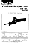
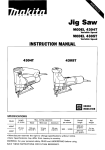
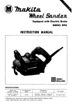
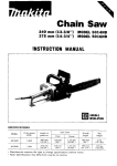
1
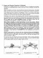
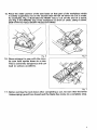
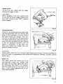
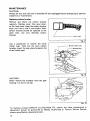
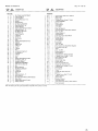
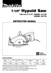
7-iw
Hypoid Saw
185 mm (7-1/4") MODEL 517 7 8
MODEL 5277B
INSTRUCTION MANUAL
DOUBLE
INSULATlON
Max. cutting capacities
Blade
diameter
185 mm
17-1/4"1
62 mm
(2-3/8")
50 O
450
No load speed
(RPMI
Overall
length
Net
weight
40 mm
(1-9/16")
44 mm
(1-23/32")
4,300
439 mm
(17-1/4"1
6.8 kg
(15.0 Ibs)
GENERAL SAFETY RULES
(For All Tools)
WARNING! Read and understand all instructions. Failure
to follow all instructions listed below, may result in electric
shock, fire and/or serious personal injury.
SAVE THESE INSTRUCTIONS
READ ALL INSTRUCTIONS.
1. Keep your work area clean and well lit. Cluttered benches and dark areas invite
accidents.
2. Do not operate power tools in explosive atmospheres, such as in the presence
of flammable liquids, gases, or dust. Power tools create sparks which may
ignite the dust or fumes.
3.Keep bystanders, children, and visitors away while operating a power tool.
Distractions can cause you t o loose control.
4. Double Insulated tools are equipped with a polarized plug (one blade is wider
than the other.) This plug will fit in a polarized outlet only one way. If the
plug does not fit fully in the outlet, reverse the plug. If it still does not fit,
contact a qualified electrician t o install a polarized outlet. Do not change
the plug in any way. Double insulation H eliminates the need for the three
wire grounded power cord and grounded power supply system.
5. Avoid body contact with grounded surfaces such as pipes, radiators, ranges
and refrigerators. There is an increased risk of electric shock if your body is
grounded.
6. Don't expose power tools t o rain or wet conditions. Water entering a power
tool will increase the risk of electric shock.
7. Do not abuse the cord. Never use the cord t o carry the tools or pull the plug
from an outlet. Keep cord away from heat, oil, sharp edges or moving parts.
Replace damaged cords immediately. Damaged cords increase the risk of
electric shock.
8. When operating a power tool outside, use an outdoor extension cord marked
"W-A' or "W." These cords are rated for outdoor use and reduce the risk
of electric shock.
9. Stay alert, watch what you are doing and use common sense when operating
a power tool. Do not use tool while tired or under the influence of drugs,
alcohol, or medication. A moment of inattention while operating power tools
may result in serious personal injury.
IO. Dress properly. Do not wear loose clothing or jewelry. Contain long hair. Keep
your hair, clothing, and gloves away from moving parts. Loose clothes, jewelry
or long hair can be caught in moving parts.
2
11. Avoid accidental starting. Be sure switch is off before plugging in. Carrying
tools with your finger on the switch or plugging in tools that have the switch
on invites accidents.
12. Remove adjusting keys or switches before turning the tool on. A wrench or
a key that is left attached to a rotating part of the tool may result in personal
injury.
13. Do not overreach. Keep proper footing and balance at all times. Proper footing
and balance enables better control of the tool in unexpected situations.
14. Use safety equipment. Always wear eye protection. Dust mask, non-skid
safety shoes, hard hat, or hearing protection must be used for appropriate
conditions.
15. Use clamps or other practical way t o secure and support the workpiece t o
a stable platform. Holding the work by hand or against your body is unstable
and may lead to loss of control.
16. Do not force tool. Use the correct tool for your application. The correct tool
will do the job better and safer at the rate for which it is designed.
17. Do not use tool if switch does not turn it on or off. Any tool that cannot
be controlled with the switch is dangerous and must be repaired.
18. Disconnect the plug from the power source before making any adjustments,
changing accessories, or storing the tool. Such preventive safety measures
reduce the risk of starting the tool accidentally.
19. Store idle tools out of reach of children and other untrained persons. Tools
are dangerous in the hands of untrained users.
20. Maintain tools with care. Keep cutting tools sharp and clean. Properly
maintained tools, with sharp cutting edges are less likely to bind and are easier
to control.
21. Check for misalignment or binding of moving parts, breakage of parts, and
any other condition that may affect the tools operation. If damaged, have
the tool service before using. Many accidents are caused by poorly maintained
tools.
22. Use only accessories that are recommended by the manufacturer for your
model. Accessories that may be suitable for one tool, may become hazardous
when used on another tool.
23. Tool service must be performed only by qualified repair personnel. Service
or maintenance performed by unqualified personnel could result in a risk of
injury.
24. When servicing a tool, use only identical replacement parts. Follow instructions in the Maintenance section of this manual. Use of unauthorized parts
or failure to follow Maintenance Instructions may create a risk of electric shock or
injury.
3
Specific Safety Rules
1. DANGER! Keep hands away from cutting area and blade. Keep your second
hand on auxiliary handle, or motor housing. If both hands are holding the
saw, they cannot be cut by the blade.
Keep your body positioned t o either side of the saw blade, but not in line
with the saw blade. KICKBACK could cause the saw to jump backwards. (See
"Causes and Operator Prevention of Kickback")
Do not reach underneath the work while blade is rotating. The guard can
not protect you from the blade below the work. Don't attempt to remove cut
material when blade is moving.
CAUTION: Blades coast after turn off.
2. Check lower guard for proper closing before each use. Do not operate saw
if lower guard does not move freely and close instantly. Never clamp or tie
the lower guard into the open position. If saw is accidentally dropped, lower
guard may be bent. Raise the lower guard with the Retracting Handle and make
sure it moves freely and does not touch the blade or any other part, in all angles
and depths of cut.
3.Check the operation and condition of the lower guard spring. If the guard
and the spring are not operating properly, they must be serviced before use.
Lower guard may operate sluggishly due to damaged parts gummy deposits,
or a buildup of debris.
4. Lower guard should be retracted manually only for special cuts such as
"Pocket Cuts" and "Compound Cuts." Raise lower guard by Retracting
Handle. As soon as blade enters the material, lower guard must be released.
For all other sawing, the lower guard should operate automatically.
5. Always observe that the lower guard is covering the blade before placing
saw down on bench or floor. An unprotected, coasting blade will cause the
saw to walk backwards, cutting whatever is in its path. Be aware of the time
it takes for the blade to stop after switch is released.
6. NEVER hold piece being cut in your hands or across your leg. It is important
to support the work properly to minimize body exposure, blade binding, or
loss of control.
7. Hold tool by insulated gripping surfaces when performing an operation where
the cutting tool may contact hidden wiring or its o w n cord. Contact with
a "live" wire will also make exposed metal parts of the tool "live" and shock
the operator.
8. When ripping always use a rip fence or straight edge guide. This improves
the accuracy of cut and reduces the chance for blade binding.
9. Always use blades with correct size and shape (diamond vs. round) arbor
holes. Blades that do not match the mounting hardware of the saw will run
eccentrically, causing loss of control.
IO. Never use damaged or incorrect blade washers or bolts. The blade washers
and bolt were specially designed for your saw, for optimum performance and
safety or operation.
4
11. Causes and Operator Prevention of Kickback:
Kickback is a sudden reaction to a pinched, bound or misaligned saw blade,
causing an uncontrolled saw to lift up and out of the workpiece toward the
operator.
When the blade is pinched or bound tightly by the kerf closing down, the blade
stalls and the motor reaction drives the unit rapidly back toward the operator.
If the blade becomes twisted or misaligned in the cut, the teeth at the back
edge of the blade can dig into the top surface of the wood causing the blade
to climb out of the kerf and jump back toward operator.
Kickback is the result of tool misuse and/or incorrect operating procedures
or conditions and can be avoided by taking proper precautions as given below.
Maintain a firm grip with both hands on the saw and position your body and
arm t o allow you t o resist KICKBACK forces. KICKBACK forces can be
controlled by the operator, if proper precautions are taken.
When blade is binding, or when interrupting a cut for any reason, release
the trigger and hold the saw motionless in the material until the blade comes
t o a complete stop. Never attempt t o remove the saw from the work or pull
the saw backward while the blade is in motion or KICKBACK may occur.
Investigate and take corrective actions to eliminate the cause of blade binding.
When restarting a saw in the workpiece, center the saw blade in the kerf
and check that saw teeth are not engaged into the material. If saw blade
is binding, it may walk up or KICKBACK from the workpiece as the saw is
restarted.
Support large panels t o miniinize the risk of blade pinching and KICKBACK.
Large panels tend to sag under their own weight. Supports must be placed
under the panel on both sides, near the line of cut and near the edge of the
panel as shown in Fig. 1.
To minimize the risk of blade pinching and kickback. When cutting operation
requires the resting of the saw on the work piece, the saw shall be rested
on the larger portion and the smaller x e cut off.
To avoid kickback, do support board
or panel near the cut.
I
Fig. 1
Don't support board or panel away
or panel near the cut.
Fig.
:
5
Do not use dull or damaged blade. Unsharpened or improperly set blades
produce narrow kerf causing excessive friction, blade binding and KICKBACK.
Blade depth and bevel adjusting locking levers must be tight and secure before
making cut. If blade adjustment shifts while cutting, it may cause binding
and KICKBACK.
Use extra caution when making a "Pocket Cut" into existing walls or other
blind areas. The protruding blade may cut objects that can cause KICKBACK.
NEVER place your hand or fingers
behind the saw. If kickback occurs,
the saw could easily jump backwards
over your hand, possibly causing
severe injury.
Fig.
12. Adjustments. Before cutting be sure depth and bevel adjustments are tight.
13. Avoid Cutting Nails. Inspect for and remove all nails from lumber before
cutting.
14. When operating the saw, keep the
cord away from the cutting area and
position it so that it will not be caught
on the workpiece during the cutting
operation.
Operate with proper hand support,
proper workpiece support, and
supply cord routing away from the
work area.
A typical illustration of proper hand
support, workpiece support, and
supply cord routing.
Fig. 4
WARN ING:
It is important t o support the workpiece properly and to hold the saw firmly
to prevent loss of control which could cause personal injury. Fig. 4 illustrates
typical hand support of the saw.
6
15. Place the wider portion of the saw base on that part of the workpiece which
is solidly supported, not on the section that will fall off when the cut is made.
As examples, Fig. 5 illustrates the RIGHT way to cut off the end of a board,
and Fig. 6 the WRONG way. If the workpiece is short or small, clamp it down.
DON'T TRY TO HOLD SHORT PIECES B Y HAND!
Fig.
Fig. 5
1
16. Never attempt t o saw with the circular saw held upside down in a vise.
This is extremely dangerous and can
lead t o serious accidents.
I
I
7
SYMBOLS
Described below are symbols commonly listed on tools.
v
S
.................................
.................................
.................................
.................................
.................................
.................................
.................................
volts
amperes
herts
kilograms
hours
minutes
seconds
%
.................................
alternating current
----
.................................
direct current
.................................
no load speed
.................................
alternating or direct current
A
Hz
kg
h
min
%
-
Dl .................................
.................................
A b .................................
.../min ................................
@ .................................
8
Class II Construction
splash-proof construction
watertight construction
revolutions or reciprocation per minute
number of blows
OPERATION
Removing or installing saw blade
CAUTION :
Always be sure that the tool is switched off and unplugged before removing or installing
the blade.
To remove the blade, press the shaft lock
so that the blade cannot revolve and use
the wrench to loosen the hex bolt clock-
wise. Then remove the hex bolt, outer
flange and blade.
Shaft lock 2
Fig.
~
To install the blade, follow the removal procedure in reverse. BE SURE TO TIGHTEN
THE HEX BOLT SECURELY.
Fig.
CAUTION:
.Be sure the blade is installed with teeth
pointing up a t the front of the tool.
.Use only the Makita wrenches to install
or remove the blade.
.One side of the inner flange is for 5/8"
hole diameter or the blade; the other side
i s for 13/16" hole diameter.
Mounting shaft
1
-Hex
bolt
Fig. 1
Use the correct side for the hole diameter of the blade you intend to use. Mounting the
blade on the wrong side can result in dangerous vibration.
9
Adjusting depth of cut
Loosen the lever on the depth guide and
move the base up or down. At the desired
depth of cut, secure the base by tightening
the lever.
I
CAUTION:
0 Use a shallow depth of cut when cutting thin workpiece for cleaner, safer cuts.
0 After adjusting the depth of cut, always tighten the lever securely.
Fig. 11
Bevel cutting
Loosen the lever on the bevel scale plate on
the front of the base. Set for the desired
angle (0'-45') by tilting accordingly, then
tighten the lever securely.
p
v
e
l scale plate
Lever
Fig. 12
Sighting
The front of the base is notched to provide
two guide edges.
For straight cuts, align the edge with 0 engraved on it with your cutting line on the
work piece.
For 45' bevel cuts, align the edge with 45'
engraved on it with your cutting line.
/
/
Fig. 1
10
Switch action
To start the tool, simply pull the trigger.
Release the trigger to stop.
1
CAUTION :
Before plugging in the tool, always check
to see that the switch trigger actuates properly and returns to the "OFF" position
when released.
Cutting operation
Grasp the rear handle with your right hand,
the front grip with your left. Set the base
plate on the workpiece to be cut without
the blade making any contact. Then turn
the tool on and wait until the blade attains
full speed. Now simply move the tool forward over the workpiece surface, keeping
it flat and advancing smoothly until the
sawing is completed. To get clean cuts,
keep your sawing line straight and your
speed of advance uniform.
Rear hand'e
I
Fig. 1
CAUTION :
Always gently keep the tool moving straight ahead when cutting. Forcing or twisting the
tool will result in overheating of the motor and dangerous kickback, possibly causing
severe injury.
Guide rule
The handy guide rule allows you to do
extra-accurate straigtt cuts. Simply slide
the guide rule up snugly against the side of
the workpiece and secure it in position
with the clamp screw on the front of the
base. It also makes repeated cuts of uniform width possible.
Fig. 16
1J
MA1NT ENANCE
CAUTION:
Always be sure that the tool is switched off and unplugged before attempting to perform
inspection or maintenance.
Replacing carbon brushes
Remove and check the carbon brushes
regularly. Replace when they wear down
to the limit mark. Keep the carbon brushes
clean and free to slip in the holders. Both
carbon brushes should be replaced a t the
same time. Use only identical carbon
brushes.
t
i
m
i
L
;
mark
L
Fig. 17
Use a screwdriver to remove the brush
holder caps. Take out the worn carbon
brushes, insert the new ones and secure the
brush holder caps.
7Brush
holder cap
I
Fig. 18
CAUTION :
Never remove the breather from the gear
housing. It is not an oil cap.
///
Fig. 1
To maintain product SAFETY and RELIABILITY, repairs, any other maintenance or
adjustment should be performed by Makita Authorized or Factory Service Centers,
always using Makita replacement parts.
12
ACCESSORIES
CAUTION :
These accessories or attachments are recommended for use with your Makita tool specified in this
manual. The use of any other accessories or attachments might present a risk of injury t o persons.
The accessories or attachments should be used only in the proper and intended manner.
0
Guide rule
Part No. 165153-3
Wrench 13
Part No. 782016-4
0
Chisel tooth combination saw blade
For rip and cross-cut work.
Most frequently used for
general carpentry.
0
Corn bination saw blade
For rip and cross-cut work
Part No.
792446-1
1
I
I
1
Diameter &
r: : id
7- 114"
,185 mm)
0
Carbide-tipped saw blade
Faster, smoother, longer sawing
without blade sharpening.
Cuts wood, drywall, plastics,
hard wood, etc.
A-90037
1
1
7- 114"
( 1)8, , 5
,,,,
518''
20
h: : ,
518''
40
13
Sep.-07-'95
US
185 mm (7-1/4")
HYPOID SAW
Model 5177B/5277B
Note: The switch and other part configurations
may differ from country to country.
14
MODEL 51778152770
$&
1
2
3
4
5
6
7
8
9
10
11
12
13
14
15
16
17
18
15
20
21
22
24
25
26
27
28
25
30
31
32
33
34
35
1
1
1
1
1
1
1
1
1
3
1
1
1
1
1
1
1
36
37
38
39
40
41
42
43
1
44
45
46
47
1
1
1
1
1
1
1
2
3
1
Sep.-07-'95
,&,
DESCRIPTION
Hex Flange Head Bolt M8xZO
Outer Flange 40
Inner Flange 40
Bearing Retainer23-36
Spindle
Woodruff Key 4
Ball Bearing 6003DDW
RetalnlnQRlng 5-42
Tension Spring 4
Tapping Screw Bind CT M5x20
Retaining Ring 5-12
Ball Bearing 6201LLB
Flat Washer 12
Hypaid Gear 36
0 Ring 50
011Seal 17
Bearing Box
LWW
Tapping Screw Bind CT 4x12
Breather
Safely Cover
0 Ring 14
Cap 20
0 Ring 5
Pin 6
CompressIan SprlnQ 6
Flat Washer 6
0 Ring 6
C0"W
Grip
Tapping Screw Bind CT 5x20
Ball Bearing 629LLB
InsulationWasher
ARMATURE ASSEMBLY
(With Item 33 34 8 36)
Fall
Bearing Retainer
Ball Bearing 6003LLB
0 Ring 16
011
Seal 22
Ring 17
Retaining Ring 5-17
Gear HOUSI~Q
Pan Head Screw M5x10 (With Washer)
Blade Case
Tapping Screw Bind CT 5x20
Rubber Sleeve 6
48
49
50
51
52
53
54
55
56
51
58
59
62
63
1 6 4
65
66
67
68
69
70
71
72
73
14
75
76
71
18
79
80
81
82
83
84
85
86
81
88
89
90
91
92
53
1
1
1
2
1
1
1
1
1
1
1
1
1
1
1
1
1
1
1
1
2
4
1
1
2
2
1
1
2
1
1
1
1
1
4
1
1
I
US
DESCRIPTION
Countersunk Head Screw M6x28
Makita Mark
Baffle Plate
Tapping Screw Flange PT 5 x 6 5
FIELD ASSEMBLY
Depth Guide
Flat Washer 8
Lever Plate
Lock Plate
Hex Bolt M8x20
Pan Head Screw M4x8 IWith Washerl
Hex Nut M 8
Spring Washer 8
Flat Washer 8
Cap Square Neck Bolt Max24
Screw M6x14
Screw M5x12
Flat Washer 8
Lever Plate
Lock Plate
Hex Nut M 8
Pan Head Screw Max8 IWith Washer)
Flat Head Screw M 8
Base
Hex Niit M 6
Spring Washer 6
Flat Washer 6
Tapping Screw Flange PT 4x20
Tapping Screw Flange PT 5x25
Flat Head Screw M 6
Flat Washer 8
Brush Holder Cap
Carbon Brush
Triac Circuit (51778 only)
Handle Set [With Item 871
Tapping Screw Flange PT 4x12
Strain Relief
Cord Guard
Cord
Handle S e t IWith Item 821
Switch
Tapping Screw Bind CT 5x30
Motor Housing
Name Plate
Breather Retainer
lNot Illustratedl
Pan Head Screw M4x12 IWith Washerl
lNot llluStrated1
Note The Switch and other part specifIcalions may differ from country to country
15
MAKITA LIMED ONE YEAR WARRANTY
Warranty Policy
Every Makita tool is thorou ly inspected and tested before leaving the factory. It is warranted t o
be free of defects from workanshl and materials for the period of ONE YEAR from the date of
original urchaae. Should any t r o u b i develop during this one-year period, return the COMPLETE
tool, fr&t prepaid, to one of Makita’s Factory or Authorized Service Centers. If inspection shows
the trouble is caused by defective workmanahip or material, Makita will repair (or at our option,
replace) without charge.
This Warranty does not apply where:
repairs have been made or attempted by others:
repairs are required because of normal wear and tear:
The tool has been abused, misused or improperly maintained;
alterations have been made t o the tool.
IN NO EVENT SHALL MAKITA BE LlABLE FOR ANY INDIRECT. INCIDENTAL OR CONSEQUENTIAL DAMAGES FROM THE SALE OR USE OF THE PRODUCT. THlS DISCLAlMER
APPLIES BOTH DURING AND AFTER THE TERM OF THlS WARRANTY.
MAKITA DISCLAIMS LIABILITY FOR ANY IMPLIED WARRANTIES, INCLUDING IMPLIED
WARRANTIES OF “MERCHANTABILITY” AND “FITNESS FOR A SPECIFIC PURPOSE.”
AFTER THE ONE-YEAR TERM OF THIS WARRANTY.
This Warranty gives you specific legal rights, and you may also have other rights which vary from
state t o state. Some states do not allow the exclusion or limitation of incidental or consequential
damages, so the above Limitation or exclusion may. not apply to you. Some states do not allow
limitation on how long an implied warranty lasts, so the above limitation may not apply to you.
~~~
~
Makita Corporation of America
2650 Buford Hwy., Buford, GA 30518
MCA 5-96
884044A068
PRINTED IN USA
1997-01-4D