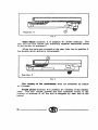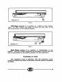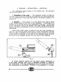
1
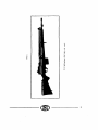
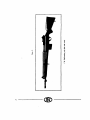
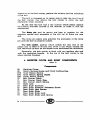
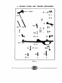
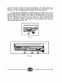
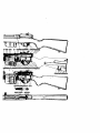
F.N. MODEL 49
SELF - LOADING
RIFLE
USER'S MANUAL
Fabrlque Natlonale
d'Armes de Guerre
Societe Anonyme
HEPSTAL- LEZ - LIEGE
(BELGIUM)
--0!>--
~
";;
~"
_;:.
E
;;"
0::
~
-o""'0
~
Qj
V)
:i
..;
3
"i
~
.,>
-o
·;;
-..
0
u:
~
~
"'
.5
-o
]
~
z
...;
GINIRAL CHARACTIRIITICI
The F.N. Self-loadlnq Rifle Is a lboulder weapcm which has been
developed to use the Infantry cartrldqes i.e. rimless
cartrid~es of a calibre of about 8 mm (7 mm, 7,5 mm.
7,65 mm, 7,9 mm, .30) developlnq a muzzle enerc;Jy of
approximately 350 kqm. This rifle con be manufactured for
all above mentioned ammunitions and calibers.
....a.ocl at as11u"r -
It is a self-loadinq rifle, I.e. that the
followlnq operations are automatically performed without
Interference of the ehooter :
Unlocklnq the mechanism,
Extraction and election of the fired case,
Cockinq the hammer,
Feedinq a cartridc;Je Into the chamber,
Lockinc;J the mechanism.
The Standard type of the F. N. Self-loadlnq Rifle is deslqned
as to deliver slnqle shot fire only.
On apecial requ. .t. however, thla rifle may be cleaiqned as to be able to
deliver either : lllnqle llhot or luu automatic lire.
Wbcl Wl&lllllll - The rifle is locked and the openlnq of the
mechanism c:m only occur when there is practically no
more pressure in the chamber. This makes the extraction
of the fired c:ase more easy and ensures a more regular
functionlnq as It Is less sensible to unavoidable variations
of ammunitions.
The bolt of the F. N. Self-loading Rifle is In one piece, it is
locked downwards at the rear of the maqazine.
Ga. Dll llr - The F. N. Self-loadinc;J Rifle is a qas operated
weapon. The qas port is located sufficiently near the
muzzle as to allow the pressure in the chamber to drop
before the mechanism is unlocked : the qas intake system
permits to toke into the mechanism exactly sufficient gas to
operate the weapon. This qas r8c;JUlation enables to suit
to atmospheric conditions as well as to variations in
ammunition.
As a consequence of the fact that only the required quantity
of qas is allowed to pass into the gas cylinder, the foulinq
of the parts submitted to the action of qas is reduced to
a minimum. On the other hand, the escape of the excess
--oro
5
of gas outside of the ;weapon sweeps continuously into the
air the residues of powder combustion, this also reduces
the possibility of fouling.
Cloaed bolt. - In opposition to the automatic machine rifles
which generally fire from an open bolt, the self-loading
rifles lire with closed bolt i.e. that the bolt is in its forward
position and locked when the trigger Is depressed.
Consequently the bolt of the F. N. Self-loading Rifle Is not
held at the rear after each shot. The bolt, after performing
automatically all its functions, returns to the forward position. This feature enables to obtain a high standard ol
aCCt;racy.
Capacity. - Owing to the capacity of the magazine 00 cartridges),
located in the lower part of the stock, the efficiency of the
weapon is greatly increased. Moreover it Is possible to
reload the magazine while partially empty.
StabUlty. - The weapon Is so designed that the center of gravity
is practically in line with the point where the stock rests
against the shoulder of the shooter. The upward swing of
the muzzle is consequently greatly reduced and there is
practically no iumping of the gun when fired. This also gives
in a high standard of accuracy.
Llqht welqht. - Notwithstanding the fact that it is an automatic
weapon, owing to a thorough study of the functions and
the resistance of the components, the weight of the F. N.
Self-loading Rifle has been kept very low.
Weather proofD.-. --- There are no openings allowing dust or
mud into the mechanism.
Safetr. - The weapon is absolutely safe, the very principle of
the relative motions of the working parts prevents the firing
as long as the locking of the mechanism is not complete.
Further, the firing pin stop prevents the forward motion of
the firing pin ln any position of the bolt except when lt is
locked. Accidental firing is consequently materially impossible.
AcceuJbUlty. - By the fact that the complete dismounting of the
working parts may be performed immediately without
using any tool, all· the components of the mechanism are
6
0!>--
easily accessible. This makes the maintenance of the
components very easy and permits to clear immediately an
accidental stoppage.
Slmplldty. - The weapon is very simple. It consists only in a
few groups of components. The instruction of the soldier
is consequently very easy.
Bolt and Bolt-carrier catches. - The bolt catch holds the bolt
open when the magazine is empty. When the rille has
been completely or partially refoaded, pulling slightly back
the cocking handle and releasing it, will release the mecha·
nism forward pushing a cartridge ahead of it into the
chamber. A hand operated bolt·carrier catch permits to hold
the mechanism in the open position with a loaded magazine.
LoadiDcJ the
CJUD. - In opposition to other weapons of similar
type, the F. N. Self·loading rifle does not require a special
clip to load the magazine. The loading can be performed
by single cartridges or by means of ordinary clips holding
5 rounds. Owing to the hand operated bolt-carrier catch,
it is possible to reload a magazine partially unloaded.
In addition to a high efficient
safety which locks the trigger mechanism and is easy to
control in the dark, the rifle is provided with a cocking
indicator, which extending below the trigger guard when
the hammer is cocked, is easily felt. When the cocking
indicator protrudes the shooter is aware that he has to set
the qun at safe if he does not intend to use it immediately.
Safety and cocldnq IDcllcator. -
a.etloD. -
Occurs to the right and forward to prevent disturbing
neiqhbouring shooters.
Graade IGUDcbJDq. -
A plug fitting the head of the gas cylinder
permits to cut inlet of gas from the barrel to the gas cylinder.
In this case the mechanism does not work automatically
and must be operated directly by hand. This device is
specially provided for the launching of grenades.
Acceuorte.. -
On special request the rifle is supplied with :
a bayonet
a blank firing attachment
a muzzle brake.
®---
7
DllcaJPTION
The main components of the F. N. SeU-loadinq Rifle are:
I. Receiver, Barrel and Gas cylinder Assembly.
2. Bolt and Bolt-Carrier Assembly.
3. Receiver Cover with Rear Siqht.
4. Trlqqer Guard with Trlqqer Mechanism.
5. Stock and Forearm.
6. MCJ9CJZ1ne with Maqazlne Platform and Platform Sprlnq.
'
I. RECEIVER . BARREL · GAS CYLINDER ASSEMBLY
s•
6~
IBlA
ID
12
13
!SA or
215A
216~
217 I
-4
15B
~
10 - - - - - - - - -
.u
t'
:::
®--
Components
I
Barrel Assembly.
lA Barrel.
18 Gas Cylinder.
IC Gas Cylinder Securing Pin.
lD Piston Guide.
IE Piston Guide Securing Pin.
3
Muzzle Cap,
5
Front Sight.
6
Gas AdJusting Sleeve.
8
Gas Cylinder Plug.
12
Piston.
13
Piston Return Spring.
15
Receiver
15A ~ Receiver Body.
or
• 215A
158 Locking Shoulder.
• 216
Safety Sear.
• 217
Safety Sear Spring.
19
Cover Plate.
The front end of the ba:rNl is threaded in order to take muzzle
The barrel is breached to the receiver and Is fitted with the
qas cylinder, which is one piece with the front siqht base, the
front sight protecting winqs and the bayonet stud. The barrel is
also fitted with the piston quide, secured to the barrel by means
of a pirt.
cap.
The 9CD cyllllc:ler Is pressed on to the barrel and is localized
by means of a shoulder and secured by means of its securing
pin. '
The qas cylinder plug, with its plunger and plunger spring,
fils the front end of the qas cylinder. The gas cylinder is also fitted
with the gas adJusting sleeve. A:n aperture cut in the front of the
receiver serves as a qulde for the rear end of the piston. The
front end of the receiver serves as a stop for rear end of the piston
return spring. Further, the piston Is controlled, in its middle part,
by the piston quide.
The top of the Neel?er, which houses the mechanism, is
completely cut open, while its underside has two openinqs : one
for the hammer at the rear, and one forward for the carlridqes.
• Camp n
Ill uaed for rlfl• allowlnq alnq!. ahot and lull automatic lire.
®
--------11
At the front of the receiver is the lead for the cartridges into the
chamber. At the rear of the receiver are: the locking shoulder
(which bemg pressed into the receiver. is a separate part so that
the correct head space carT be obt:::Jined) and the housings for the
holding open device and for the ejector. On the side, the receiver
is fitted with flanges in order to lead the bolt carrier.
If the rifle 1s desaqned to deliver single shot and full automatic fire, a safely
sear and ils spnnq. which forces the sear bacir. afler lhe hammer hal been
!Jb<rated. are anached lo ll:e receiver.
f'h<~
upper part of the receiv€:r is fitted to secure the receiver
cover.
The underside of the receiver has three threaded holes for
the screws assembling the receiver to the stock and to the trigger
guard.
12------------------
2.~M
11!!111
-
•
-..
-
...I
27 •• 117
II
•
u
15
Plate IV.
21
22
23
Bolt.
Extractor.
Extractor Sprinq.
24 Flrinq Pin - Front End.
25 Flrinq Pin SprinQ.
~~ ~ Flrinq Pin Safety Stop.
or
• 227
28
Bolt Carrier.
Flrinq Pin - Rear End.
The bolt houses the extractor and Its sprinq, the flrinq pin
and Its sprtnq and flrinq pin safety stop. It has one luq at the
front and two luqs at the rear. These two luqs cammed by the
• Componenl uMd lor rifiea atlowlnq alnqle ahol and lull automarlc: lire.
------------------- ~ ------~---------13
slopes cut in the bolt carrier, perform the locking and the unlocking
of the bolt.
'
The bolt is recessed on its upper side to take the iron! lug of
the bolt carrier. this allows the bolt carrier to carry the bolt
rearwards when recoiling.
At the rear the bolt has a flat surface which bears against
the locking shouider located in the receiver, in order to lock the
mechanism.
The flriD9 pill and its spring are kept in position by the
extractor spring stud engaging in the slot cut in flrinq pin rear
end.
The firinq pin safety stop prevents the protrusion of the firing
pin until the bolt is properly locked.
The bolt carder, against which strikes the rear end of the
piston rod, is fitted at its fore end whith a luq which carries the
bolt rearward as soon as the slopes have performed the unlocking.
Externally, the bolt carrier is fitted with two guiding ribs and
with the operatinq handle. In the top of the bolt carrier is the
return sprlnqs housing.
3. RECEIVER COVER AMD SIGHT COMPONENTS
(Plate VI
Ca~~q~aa•ts
65
66
67 A
67C
670
70
71
72
73
74
75
76
77
78
79
a
Receiver Cover.
Return Sprinqs Guide and Cover Locking Key.
Inner Return Spring.
Inner Return Spr!9g Guide.
Outer Return Spring.
Bolt Carrier Catch.
Bolt Carrier Catch Stop.
Bolt Carrier Catch Spring.
Sight Leaf.
Rear Sight Aperture.
Rear Sight Aperture AdJusting Screw.
Rear Sight Leaf Spring.
Rear Sight Slide.
Rear Sight Slide Lock.
Rear Sight Slide Lock Spring.
® ----------
I
"
...
75
73
7.
-
79
I
78
•
'76
0
t
•
65
~·
?I
70
71
....
67A
67
c
67A
~
67D
Plate V.
The Rec:elYer coYer houses the return springs and their guide,
the receiver cover locking key and the bolt carrier catch. On the top
of the cover is the rear sight base which supports the sight leaf, with
the rear sight slide and the rear sight aperture. The fore end of
the receiver cover is recessed to take the clip when the cartridges
are introduced in the magazine.
-----------------15
4. TRIGGER GUARD AND TRIGGER MECHANISM
~3IA . . . .IA
39
or
239 .....
41 '
3
co I
'~~
42
36
43A'
44
I
35
43B
Sl
30
'-..
or
~
43C o
::a
~
137
45A 45B -
138
46 . . . .
230
9
J
ssJ
5.f-
ssl
•
S8 '
Plate VI.
16---------------
232=1.
~1
&
or /
•239
40
41
42
43
43A
438
43C
44
45A
458
46
51
52
53
54
55
56
57
58
• 232A
• 2328
•232C
A=illorr
s..,.
Auxiliary StKir Spring.
Auxiliary Sear SprinQ Plunger.
Trigger Axis Pin.
Bolt Stop, complete (Holding Open Device).
Bolt Stop Body.
Bolt Stop Spring.
Bolt Stop Washer.
Bolt Stop Retainer.
Bolt Stop Retainer Plunger.
Bolt Stop Retainer Plunger Spring.
Safety, complete.
Eiector.
Magazine Catch.
Magazine Catch Spring.
Magazine Catch Axis Pin.
Trigger Guard Front Screw.
Trigger Guard Center Screw.
Trigger-Guard Rear Screw.
Trigger Guard Screw Stop Screw.
Automatic Fire Lever Body.
Automatic Fire Lever Arm.
Automatic Fire Lever Arm Plunger.
• Components used lor rill•• allowinq ainqle shot and lull automatic lire.
-------------------~ -----------------17
• 2320
• 232E
* 232F
Automatic Fire Lever Arm Stop.
Automatic Fire Lever Stud.
Automatic Fire tever Locking Screw.
The Trlqqer quard is fixed to the receiver by me:ans of three
screws and stop screws.
The trigger guard holds the hammer and its springs, ihe
hammer spring guide (which also acts as a cocking indicator), the
trigger, the trigger spring and the trigger spring plunger. The
trigger guard also holds the auxiliary sear, its sprlnq and its
spring plunger and the safety. In the case of rifles designed to
lire automatically the trigger guard also holds the automatic
fire lever.
In the front of the trigger guard is the magazine housing. In
its middle part the trigger guard holds the magazine catch, its
spring, the bolt stop and its spring and the ejector.
S. STOCK · HANJ>GUARP
(Plate VII)
85A
or
• 285A
858
SSE
85F
86A
868
86C
86D
86E
87
88
89
89A
898
89C
90
STAIB
STA.l9
!
Stock.
J
Trigger Guard Rear Screw Bushing.
Recoil Lug.
Recoil Lug Nut.
Handguard Body (2 parts).
Handguard Front Cap.
Handguard Front Cap Rivet.
Handguard Rear Cap.
Handguard Rear Cap Rivet.
Stock End Cap.
Stock End Cap Screw.
Lower Band assembly.
Lower Band Bodv.
Lower Band Screw.
Lower Band Screw Retaining Collar.
Swivel. complete.
Swivel Plate and Butt Plate Screw.
Swivel Plate Pin.
• Components uaed lor rilles allowinq ainqle shot and lull automatic lire.
18 - - - - - - - - - - - - - - - - - -
~
--------------------
86 B.C.
.187 -
88
89 A
86 A
G
86 D.E.
89
s.c.1J so
85E
85F
-
0
85 A
or
-858
STA 20
STA '1:1
&,
--
STA IE
STA 26
'1 ~ 1
STA18
Plate VII.
----------------~ ---------------19
STA.20
STA.27
STA.26
Swivel Plate.
Swivel.
Butt Plate. Standard Type.
•• For steel b1Jt1 pla!e w1th trap and brass butt plate with trap see Plates
Vlll and IX.
STEEL BUTT PLATE WITH TRAP
STA 54
- t
STA 55
STA 52
STA 51
Plate VII!
Compoanta
STA.SI Bu_tt Plate with Trap.
STA.52 Butt Plate Trap.
STA.54 Butt Plate Trap Plunger.
STA.55 Butt Plate Trap Spring.
w ------------------
lllA88 IU'TT PLA,TE WITH TllAP
e
Dill
1''
STA 36 STA 35 STA 32
~
STA 34
STA 33
Plate IX.
Compm"mla
STA.32
STA.33
STA.34
STA.35
STA.36
Butt
Butt
Butt
Butt
Butt
Plate.
Plate Trap.
Plate Trap Pivot.
Plate Trap Sprill9·
Plate Trap Spring Screw.
The atock, in one piece, is made of walnut and consists of
the fore-end and the butt.
The for.and is fitted at the front to hold the cap, and recessed
further back for the lower band. Underneath, the butt is fitted with
the butt plate, which is secured by means of two screws.
The stock is grooved to take the barrel, the receiver, the trigger
guard, the magazine and the recoil lug. The housing of the rear
screw of the triqger guard holds a bushing.
The top of the barrel is covered with a handquard fitted with
a front cap and a rear cap. The rear oap is seated in a recess
provided in the front end of the receiver. The handcniard, In two
pieces, is secured at its front end by the front end cap, in the
middle by the lower band and at the rear by the .receiver.
For rifles used by snipers the stock can be fitted with a cheek
piece which is secured to the stock by means of screws.
------------------- ~ -----------------21
6. MAGAZINE WITH MAGAZINE FOLLOWER
AND FbLLOWER SPRING
61
2
62
60
Plate X.
Component•
60
61
62
Magazine Assembly.
Magazme Follower.
Magazme Follower Spring.
The Magazine holds 10 cartridges and can be removed from
the rifle. In front it 1s held in position in the trigger guard by
means of a hook, and at the rear by the magazine catch.
The follower sprmg rmses the cartridges, through the magazine
follower.
22-------------------
1. ACCESSORIES SUPPLIED ON SPECIAL REQUEST
I
5
'j
501
2
503
~
STA 44
506
S07
Plate XI.
U.t of Acc:euoriH
2
503
506
STA. 44
STA. 45
507
93
Bayonet.
Scabbard.
Muzzle Brake.
Blank Firing Attachment.
Barrel Cleaner.
Barrel Cleanl.nQ Brush.
Chamber Cleaning Brush.
Cleaner Case.
Sling.
N. B. - The key SOl is supplied with each rifle, it is used for
adiustement of the gas.
----------------~
HOW THE F. N. SELF-LOADING
RIFLE WORKS
The gun being ready for firing the action on the trigger
releases the hammer. Under the tension of its springs, the hammer
strikes the firing pin, which in turn strikes the primer of the cartridge
and ignites the powder charge.
!st. phase. -
The
bolt opeu UDder tbe actloD of tbe qaa.
A small amount of gas escapes through a port bored In the
and passes in the gas cylinder where it kicks the piston back.
The piston drives the bolt carrier back. The bolt carrier unlocks the
bolt and pulls it upwards to the rear. Thg extractor. which fits to the
bolt. draws the empty shell out of the chamber. When the empty
case is completely disengaged from the chamber its bottom
strike:; the ejector which ejects it to the right out of the gun. In
its backward motion the bolt carrier cocks the hammer and
compresses the recoil springs.
ba~rel
2d. phase -
The bolt Is eloMd UDder tbe te.loD of n~eoU IIPdD9L
As for any weapon firing with closed bolt, as soon as the
bolt carrier has completed its backward motion, the recoil
springs drive it forward. The bolt earner itself forces the bolt
forward. The bolt drives a cartridge ahead out of the magazine
and pushes it into the chamber. The bolt Is then locked downwards
in the receiver by the action of the bolt carrier.
DETAILS OF OPERATION
1. THE ENGINE
In addition to the barrel (lA), the components of the engine
are: the gas cylinder (!Bl. the piston (12) and its spring (13), the
gas cylinder plug (8) and the gas adjusting sleeve (6).
SIDqle •hot cmd full automatic fire
In the F. N. Self-Loading Rifle, the utilization of gas presents
several outstanding features :
2~
--------oro
F'iq. I.
a) Short CJCD cyUnder. The gas cylinder (IB) is a very
short tubular element, easily cleaned, after the gas cylinder plug
and the piston have been removed. As experience has shown that
the gas acted on the piston in the way of a hammer blow, without
any expanding, the long cylinders which were generally, used in
gas operated rifles, have consequently become useless.
b) Gcu escape. - After they have acted iri the way of a blow
on the piston, the gas escape outside through a slot (A) located on
top of the front end of the gas cylinder.
The handicap of. the gas operated weapons being the fouling,
the advantage of this gas escape system is the permanent
sweeping outwards of the combustion residues.
c) Gaa requlalloD. - The size of the slot for the escape of gas
and its location are such, that when it is completely open the
pressure exerted by the gas on the piston is insufficient to operate
the mechanism. That is the point where the regulator intervenes.
The regulator is built from a simple· threaded sleeve (6), screwed
around the gas cylinder. When the sleeve Is screwed in, the
opening for gas escape decreases and consequently the thrust of
the gas on the piston is growing, a good functioning of the rifle,
without undue fatigue for the mechanism, is thus ensured. The
gas regulation is carried out by the manufacturer, when the rifle
is assembled. It may not be changed by the soldier. The regulator has therefore been intentionally located under the handguard.
On the other hand, it is a very easy task for the armourer to refix
the gas regulation if, eventually, another regulation has to be
adopted, either in order to use a lot of special ammunition, or to
use the rifle in a country in which the atmospheric conditions are
completely different
0!>--25
d) llldepeacleace of the piMoa. - The piston (12) and the bolt
carrier (27) are located in a ·straight line, without any connection.
The return of the piston is performed instantly under the action
of its own sprinq (13) without the interference of the return sprinqs.
It is owing to this oriQin::d feature that it is possible to load the
gun the same way as a repeatinl;r rifle.
Turning 180" ihe gas cylinder plug (8A), cuts the inlet of the
gas. The piston does not transmit any thrust on the bolt carrier.
The rifle can then be used like a repeater by pulling the bolt
carrier by hand.
2. HOW THE OPENING AND THE CLOSING
OF THE MECHANISM IS OPERA TED
The components acting in this phase are: the receiver OSA)
or (215A) the bolt (21), the bolt carrier (27) or (227), the return
spring (67 A - 2 pieces - and 0), the cover (65).
The bolt .carrier (27) or (22:') moves alonQ the receiver USA)
or (215A). It is pushed rearwards by the piston (12) and is forced
forwards by the 2-piece return spring (67 A). The bolt is in one piece
and its positive locking is performed when Its flat surface at the
rear is in line with the locking shoulder made In treated steel and
pressed In the receiver at the rear of the magazine. The respective
motions of the bolt and of the bolt carrier are controlled as
follows:
When the cartridge is fired (posihon 1), the bolt is in its
locking position A and Is located in this position by the contact of
surface B of the bolt carrier.
The opeDIDq operatloD may be schemed In three phases :
26 - - - - - - - - -
Flnt Phaae (position 1 to position 2) : Break of contact of the
surface at B. The bolt Is stlll locked (Al while the pressure in
barrel is dropping.
Position 2
FIQ. 3.
SecODCl PhCIM (position 2 to position 3) : Unlocking of the
mechanism. The contact between surfaces C forces the bolt up.
----------------~
Position 3
f"iq. 4.
Third Phaae (position 3 to position 4) : Direct openlnq. The
bolt and the bolt carrier are travelling toqether rearwards owinq
to the contact of surfaces F.
When the parts are stopped at the rear, they are in position 4,
the double return sprinq is compressed.
Position 4
Flq. S.
The clcmnq of the mecbcmluD may be schemed as below
in 3 phases:
Fourth phase (position 4' to position sr: Closlnq of the mechanism. The bolt carrier pushes the bolt forwards owinq to the
contact of surfaces G till the bolt is stopped by rear end of the
barrel.
28------------------
Position 5
FIQ. 6.
FUih PbaH (position 5 to position 6) : Lockinq of the mechanism. At this moment the slope H forces the rear part of the
bolt downwards, in the lockinq position.
Position 6
FIQ. 7.
Sbdla PbaM (position 6 to position 1). Confirmation of the
lockinq. The bolt carrier continues Ita movement forward and the
bolt Ia maintained In the lockinq position by the aurfacea B.
The repeatlnq cycle Ia Identical with the automatic cycle.
Instead to receive the thrust of the piston, the bolt earrler Ia operated
by hand.
----------------~
3. FEEDING -
EXTRACTION -
EJECTION
The additional parts actin'g in this phase are : the extractor
(22) and the eiector (51).
a) Extraction of the caae. - The extractor which is fitted on
the right side of the bolt performs this operation by direct extraction
for the withdrawal of the case (see above : 3d phase- position 3 to
position 4).
b) EJec:tioD. - The ejector is of the fixed type and is fitted
in the trigger guard at the rear of the magazine. It protudes in a
groove cut at the left and in the underside of the bolt. At the end
oi the rearward motion (3d phase), the case strikes against the
ejector and being compelled to pivot around the extractor is ejected
rightwards.
There exist other types of ejectors but the type choosen for
the F. N. rifle has the great advantage to help the shooter to know
how his rifle is working, as the ejection occurs nearly at the end
of the travel of the bolt to the rear at the moment when its Is at
the point to be stopped against the rear wall of the receiver.
r, __
-- --
I......JJ
--
l"iq. 8.
A violent ejection shows that the recoil motion develops at
a too Qreat velocity and with a needless violence to perform
the funcllonlnq, with the consequence that the wear and tear of
the mechanism is amplified. Thanks to the requlator, it Is then
30---®
very eas'y to ensure, with ~ thorouqh knowledge of the whereabouts a perfect functioning of thb rifle.
With ejectors which are lilted elastically on the receiver this
cannot ba reached.
c) Introduction of a cartridqe. - The bolt has two ribs on its
lower side, these ribs, when )he bolt is closing (see above
4th phase, - position 4 to position 5) push alternatively the left
or the right side cartridge directly into the chamber.
As soon as the cartridge leaves the lips of the magazine, it
is caught by the extractor and moves with the bolt. This characteristic, taken from the best repeaters, presents several advantages :
l. The double feedin~ is impossible ;
2. The extractor is spared, because it has not to go over the
rim of the cartridge as it is the case when the cartridge is first
introduced into the chamber.
3. The closing is smoother. It ought to be mentioned that the
closing is only due to the energy stored durinq the recoil in the
springs and not to a positive mechanical action.
4. HOW THE FIRING ACTION WORKS
For rilles firing only single shot, the firing action is fitted in
the trigger guard (30) and consists of :
- The hammer (31Al with its sprin~s (34A-Bl and its guide
(31 8) which serves also as a cocking indicator.
-
The trigger (36) which serves as the principal sear.
-
The rear hook acting as the auxiliary sear (39).
-
The safety (46).
The firing of the cartridge occurs by means of a firing pin (in
two parts) (24-28) housed in the bolt.
The characteristics of the mechanism are as follows :
- - - - - - - - - 31
flq
9.
fig. 10.
Action of rifle firinq only 1inqle 1hot ftre.
a) Separation of the 1hot1 in 1inqle 1hot fire. - The device
which allows to lire exclusively shot by shot, has been taken over
from an outst::mding weapon (The Browning automatic shotgun).
Since more than SO years it el!sures a perfect functioning to this
popular gun.
The hammer (31 Al is forced backwards by the recoil of the
bolt and bolt carrier and it is in any case caught by the double
hook. which is made up by the front end of the trigger acting
as the main sear (36) and by the linked hook actinq as the
auxiliary sear (39).
Indeed if. per chance, owing to the effect of the recoil the
hnger of the shooter has left the trigger at the moment the hammer
is sent backwards, the hammer is directly caught by the main
sear (36). If on the contrary, which is generally the case, the trigger
1s still depressed by the finger, the hammer is caught by the
auxlliary sear (39) which has been put on its way by the motion
of the trigger. The hammer is caught in this position as long as
the trigger 1s depressed. In order to fire the next shot one has first
to release the trigger. - The hammer is then released by the auxiliary sear (39) but is at once and unavoidably caught by the r ...,in
sear (36). To fire again one has to depress the trigger once more.
32-------------------
Fiq. 11
Fiq. 12.
Action of rUle flriDq 11Dqle lhot and full automatic fiN
for rifles at?1e to shoot either ainqle shot or lull automatic lire, the lollowlnq
parts are desiqned as to deliver this kind of llrinq, their item number are
then as follows:
Auxiliary sear (39) superseded by auxiliary sear (239) :.
Hammer (31 A) superseded by hammer (231 Al:
Receiver body (I SA) ouperaeded by receiver body (21 SAl :
Bolt carrier (27) superseded by bolt carrier (227):
Triqqer quard (30) superseded by triqqer quard (230) :
Stock (8SA) superseded by stock (285A).
further on the lollowinq parts are used :
Safety sear (216A);
Safety sear sprinq (217) ;
Automatic lire lever (2.32).
S.. th... components on liQ. 11 and 12 as well as the sectional view of weapon
at the end ol this pamphlet.
It ouQht furthermore to be noticed that :
J• The weapon being on safety, with the trigger locked, the
cocking of the rifle by hand is possible owing to the oval slot (A)
of the hammer, which is consequently able to move longitudinally.
2" If the finger depresses the trigger at the moment the hammer
returns backwards any shock to the finger is prevented owing to
the elasticity of the linkage of the auxiliary sear.
b) Double pull. - This is the result of the action of the auxiliary
sear spring which resting against the trigger cooperates with the
trigger spring and gives the shooter the feeling of a • double pull •
motion.
----------------33
c) Cocldnq indicator.
As the hammer is completely
concealed in the weapon. it is desirable that there should be a
way to make surf' externally .if the riile is ready or not for action.
To this end, the gu1de (318) of the hammer spring protrudes beneath
the trigger guard when the hammer is cocked. It is thus easy,
even in the dark, to make sure by mere feeling if the hammer is
cocked or not.
d) Safety. - The safety (46) is located or, the side of the
trigger guard, it is consequently very easily accessible and is
easily actuated without removing the hand from the butt.
As the angle between the positions • fire • and • Safety • is
important, the safety is easily felt in the dark and even visible
from a cert:::~in distance.
The arm of the safety is fitted, inwardly, with a spring plunger
which fixes it in the selected position. In the • safety • position,
the safety wor,ks like a skid against the trigger in such a way that
the more the action on the trigger is shmp, the more the aafety is
confirmed.
FuU
1111~
lire.
In a rifle equiped lor lull automatic lire, the worltinq of the action lo different
from that oi the sinqle shot lire in the lollowinq points :
As the automatic llre·lever (232) 11 located In the pooltlon • A • : the cylin·
drlcal 1=art of the lever body Ia In contact with the tang of the auxiliary Mar 1239)
and prevents the oear to pivot forward when the trigger Ia depreued. The
enqaqement of the hammer (231A) by the auxiliary oear Ia conaequentl,y lmpoa·
aible when the trigger is depressed. In other words, th" auxiliary oear (239) io
owltched out and does not interfere any more in the action.
On the other hand, ao long aa the trigger ia depressed, the main Mar being
no more in the way of the hammer (231): this is not catched alter each ahot. The
'main oear is however superseded by the safety sear (216) whose rear end
penetrates a groove in the hammer and keeps it at the rear until the bolt-carrier
comes t:ack to ito forward . :.>Osition. The safety oear Ia then pushed forward•
by the bolt-carrier and Ito spring (21 7) compresaed. The hammer lo then free
to be flung forward unaer the a:tlon of Its opringa (3-4-A-Bl.
When the trigger io released, the main oear, which Ia one piece with the
trigger, Ia again in the way of the hammer and catch81 the hammer rearwardo,
a:opplng consequently the firing.
5. LOADING
The reloading of the rifle as il is designed with its piston
on top of the barrel. is possible owing to :
1· The independence of the piston and of the bolt carrier,
which en:::lbles the piston to move back to its location under. the
3~-----------------
action of its own spring as soon as It has thrown the bolt carrier
rearwards.
'
2° The action of the holding open· device which holds the bolt
and bolt carrier to the rear.
F'lq. 13.
This device (43A) consists of a plunger located vertically at
the rear of the magazine and in front of the bolt when the bolt is
in its lull rearward position. The spring/.of this plunger, keeps
the plunger downward, In its housing i~he trigger guard, and
consequently out of the functioning of the weapon as long as
there are cartridges in the magazine. When the last cartridge
has been fired and the bolt has travelled to the rear, the magazine
platform rear end engages the front end of the bolt stop, lifting
the stop in front of the bolt and preventing It to return in the closing
position. The shooter is consequently warned that the magazine
of his rifle is empty.
As the piston has returned to its forward position and as the
bolt is held to the rear, the magazine is open to be ~elilled. It is
only necessary to insert two clips, with 5 rounds each, one alter
each other in the grooves out in the receiver and to press, with th!!l
thumb of the right hand, on the upper cartridge of each clip in
order to introduce the 2 bundles of 5 cartridges into the magazine.
Alter the cartridges have been introduced into the mac;razlne,
---------- 01> ---------
35
closinq the rifle only requires a short pull on the operatlnc; handle,
so introducinq a cartrldqe •Into the chamber. Pullinq of the
operatlnq handle compels Indeed the bolt to withdraw relea11inc;
the holdinq open device which withdraws in Its houslnq under
the action of its sprinq.
If it is desired to refill the maqazine before II Is empty in order
to Qive the rtfle Its full potentiality of fire, the bolt carrter stop is to
be used.
This stop is fitted on the left side of the cover and is perfectly
accessible to the thumb of the right hand after pulling operatlnq
handle, and consequently the bolt, to the rear.
The retraclinq of this slop Is the same as that of the automatic
holding open device.
6.
SAFEGUARDS
The functionlnq of the hand safety, which locks the triqqer,
has been described before.
Further, as detailed below, the rifle may be carrted with
10 cartridges In the magazine, without cartridqe In the chamber.
In order to be ready for firing, only pull operal1n9 handle fully
rearwards and release it.
Flq. 14.
There are two internal safequards which make the firlnq
impossible so long as the rifle is not duly locked.
I" The first of these safequards is performed without the addition of any part, it results only from the relative motions of the bolt
36--®
and of the bolt carrier. In fact, the hammer can only reach the
firing pin when the bolt is locked and positively confirmed in this
position by the complementary mplion of the bolt-carrier.
2• The second safeguard is performed by means of a firing
pin stop (26) which prevents the striker to protude in the la::e of the
bolt so long as the locking of the rifle is not performed, as the bolt
carrier prevents any motion of the firing pin stop upwards (see
fig. 15). On the contrary. when the rifle is lo:::ked, the firing pin
stop is allowed to raise and does no more prevent the motions
of the firing pin (see fig. 16).
fiq. 15.
Flq. 16.
----------------~
HOW TO HANDLE THE RIFLE
TO MAKE, THE GUN SAFE
With thumb of right hand, rotate safety lever downwards. In
this pos1t1on of safety lever, trigger is positively locked. Moreover
safPty lever prevents the finger of the shooter to reach the trigger.
It is so very easy, even in the dark, to make sure that the gun is
safe.
To release safety, reverse the movement ol safety lever
upwards. with index hnger of nght hand.
TO OPEN AND TO CLOSE THE BOLT
To open the bolt, grasp with right hand operating handle and
draw it fully back. If there are no cartridges in magazine, bolt
will be held in the open position by bolt catch which, under the
action of magazine platform. protrudes before the bolt.
To close the bolt, push down magazine platform with thumb
of left hand. at the some time draw bolt carrier slightly back with
right hand. Under the tension of its spring, bolt catch is forced
down and does no more protrude in the path of bolt. Release
gently mechanism forward, withdraw left thumb when bolt is
above mQgazine platform.
LOADING THE RIFLE
With right hand, grasp operating handle and pull mechanism
to the rear. The mechanism will be held open by the bolt catch.
Loading the gun may be carried out either by inserting single
cartridges into magazine, or by means of 5 rounds clips. When
the loading is completed, draw slightly back slide handle and
let it go, mechanism will close forward under the !hension of
recoil springs, pushinQ a cartridge into the chamber.
The magazine holds 10 cartridges but it is not necessary to
fill it, the mechanism will close in the same way whatever the
number of cartridges in magazine may be .
.Jt is possible to close the mechanism without introducinQ a
cartridqe into the chamber with the magazine loaded with 10
rounds : with riqht hand, grasp o-perating handle and pull it
slightly ba=k. with thumb of left hand push down cartridqes of
magazine and release qently the mechanism, retaining it with
riqht hand. The mechanism will so close above the top of the
cartridges in the magazine and there will be no round In the
chamber. This is an oriqinal way to transport safely the loaded
~------------------
®--
gun. To make the weapon ready for firing, one has just to cock
the mechanism to Introduce a c101rtrid:;e into the chamber.
If the weapon is partially unloaded. it is possible to complete
the loading of the magazine : grasp operating handle with right
hand, pull mechanism fully rearwards. With thumb or right
hand depress bolt carrier catch and release operating handle,
the bolt carrier will be held In the rear position by bolt carrier
catch.
Complete the loadinq of maqazlne, pull slightly back operating
handle, bolt carrier catch will release .the bolt -carrier. Release
operatinq handle, mechanism will close pushlnq a round into
the chamber.
The possibility to load the gun either with single rounds or
standard clips, and the possibility to complete the loading of
maqazlne are orlqlnal features of the F. N. self loadinq rifle. In
comparison to similar weapons.
Unloading the qun may be carried out In two ways :
The first method Is to cock. the gun, without firing, with the
safety on. as many times as there are cartridges in the magazine.
When the magazine is unloaded, the mechanism will be held in
the rear position by bolt catch. In order to close the mechanism,
with left hand, push down magazine platform. while right hand
pulls operating handle slightly backwards, release gently
mechanism.
The second method is a follows : release magazine by pressing
with nose of·cartridge on magazine catch. while other hand gathers
magazine and cartridges, cock the gun in order to eject cartridge
inserted in chamber. Replace magazine.
All operations necessary for loading or unloading may be
performed with gun on safety. The safety does not prevent the
motion of mechanism either forwards or rearwards.
FIRING THE RIFLE
TQ fire. put safety off. sight the rifle and depress the
trigger.
With
a
rille fitted for the full automatic shooting; to shoot :
Sia9le ahol fire. - Put !ire lever 1n position • S. A. •, put safety in the • off •
pos111on. Sight the nfle and depress the trigger. Ea=h time the trigger is depressed
a shot w1ll be fned.
FuU CNiomatk lire. With the fire lever put in position • A •. put safety
• off • by turning safety lever. Sight the rifle and depress the trigger. The firing
w1ll be automatically performed as long as the trigger is depressed and as long
there are carlrldges in the magazine. The firing stops as soon as the trigger
11 released.
01>--39
STRIPPING AND ASSEMBLING
L nELD STRIPPING AND ASSEMBLING
STRIPPING THE MECHANISM
Turn receiver cover locking key 180" upwards. grasp receiver
cover and slide it forward against action of recoil springs, raise
slightly rear end of receiver cover in order to disengage cover
trom guides in receiver. Release cover rearward. Cover and
recoil spnngs will so be removed from receiver. Grasp operating
handle and pull back bolt carrior and bolt assembly until guides
of bolt carrier are In line with clearance cut in guides of receiver.
Lift fronl-end of bolt carrier and bolt assembly and remove bolt
carrier and bolt assembly from receiver. Remove bolt from bolt
carrier.
STRIPPING THE BOLT
First remove firing pin stop. Using nose of cartridge, lift
extractor spring out of spring housing cut in bolt and rot~te
extractor spring 90''. Remove extractor. Grasp bolt at both ends
between thumb and index finger. Push firing pin in bolt. Remove
extractor spring, firing pin and firing pin spring. Take firing pin
spring off firing pin.
REMOVING THE PISTON
Using nose of cartridge depress gas cylinder plug catch and
rotate plug 90'•. Remove gas cylinder plug. Tilt rifle forword,
piston and piston spring will slide out of gos cylinder. Remove
piston spring from piston.
STRIPPING THE MAGAZINE
Using nose of cartridge, lift magazine catch and remove
magazine from trigger guard. Remove magazine platform and
platform spring. Disengage magazine spring from magozine
platform.
The weapon is so disassembled for complete cleaning.
ASSEMBLING THE BOLT
Replace firing pin spring on firing pin. Replace firing pin
and firing pin spring in bolt. Depress firing pin in bolt and replace
~0 - - - - - - - - -
Q!)--
extractor spring head in bolt (extractor spring being at an angle
of 900 with the bolt). Release firing pin which, under the tension
of firing pin spring will hold extractor spring. Replace extractor
in its seat. Rotate extractor spring 90" in order to ir.sert it in
extractor seat. Replace firing pin stop.
ASSEMBLING THE MECHANISM
Replace bolt in bolt carrier. Seize bolt and bolt c:::mier
assembly at both ends between thumb and index and replace
bolt and bolt carrier assembly in re:::eiver to enable guides of
bolt to pass through clearance cut in guides of receiver. When
bolt and bolt carrier assembly is home push it forwards. Grasp
receiver cover, turn upwards cover locking key, insert recoil
springs in hole ol bolt-carrier. Compress re:::oil springs pushing
cover forward.
Replace cover downwards in receiver, front end first, and
release cover as to allow it to drop backwards fully home in its
guides. Turn cover locking key downwards. Test motions ol
mechanism a few times by hand in order to make sure assembly
is correct.
ASSEMBLING THE PISTON
Replace piston sprirtg on piston, replace piston and piston
spring in gas cylinder (head ol piston turned to the muzzle).
Replace gas cylinder plug, depressing plug catch, and turn plug
in such a way that letter A is turned outside. Release gas cylinder
plug catch.
ASSEMBLING THE MAGAZINE
Insert magazine platform spring in magazine platform. Replace
magazine platform and spring in magazine, take care to replace
them in correct position. Seize magazine and introduce magazine
in trigger guard, engaging first froni stud of magazine in recess
in trigger guard. Press on magazine bottom until magazine is
caught by magazine catch.
IL COMPLETE STRIPPING AND ASSEMBLY
The rifle ought first to be stripped as described for the field
stripping.
----------------~1
COMPLETE STRIPPING OF THE RECEIVER COVER
Remove the return sprmgs by disen:;!agmg, with the help of
a screw-driver. the first coil of the inner sprmg from the end of
its rod. Separate the outer spring from the inner springs and the
inner spnngs from their guide.
To stnp the backsight : depress tail of sight leave in order
to compress the stght spring and to disengage the leave studs
from the shoulders. Draw back the sight leave an::l remove it
from the cover. Remove the leaf spring from its housing, using
the hole cut in the spring. Grasp rear of leaf in right hand.
with the left hand grasp the sight slide and slide lock,
depress slide lock, and remove slide an::l slide lock from the leaf.
Remove slide loc:k and its spring from the sight slide.
Unscrew the two lateral adjusting screws and remove rear
sight aperture.
In order to strip the bolt carrier catch : with the help of the
point of a bullet depress the bolt carrier catch spring, this will
allow to turn the bolt carrier catch body outwards. Remove the
spring, remove the catch by raising it. remove bolt carrier c:atch
stop.
STRIPPING OF THE HANDGUARD
Unscrew front end cap screw. Remove front end cap from
the front. Remove front part of handguard swinging its front end
upwards.
Unscrew lower band screw which will free swivel ; lower
band is so able to open. Remove lower band from the front.
Remove rear part of handguard. swinging its front end
upwards.
STRIPPING THE GAS REGULA TOR SLEEVE
With the handguard removed. it is only necessary to unscrew
gas regulator ~leeve using, if necessary, gas regulator key_
Remove gas regulator sleeve.
STRIPPING THE BARREL - RECEIVER ASSEMBLY
Uns:;rew trigger guard stop s:::rews. unscrew and remove
trigger guard screws. the bGurel-receiver assembly may thus be
removed from the stock.
~2------·------------
®--
To remove cover plate, raise ill! front end in order to· disengage
it from its groove and swing the cover 90".
In the c:aM of rifles lilted for the lull automatic firinq. with the barrel·receiver
aoMmbly removed from the stock it is possible to remove the safety sear from the
recetver. O.preu safety sear forwards and at the same time diMnqaqe safety
sear from ita housinq by raioinq il. The safety sear and ill oprinq are thus frH.
STRIPPING OF THE TRIGGER-GUARD
With the trigger guard screws and their stop screws removed,
it is possible to remove the trigger guard assembly fr<Jm the
stock.
In order to remove the bolt stop, dePmaa the bolt stop retainer
plunqer, remove bolt stop retainer, bolt stop retainer plunqer and
its sprinq. Remove bolt stop.
In order to dismount the ejector and the maqazine catch and
its sprinq, remove, from left to riqht the maqazine catch axis pin.
In order to dismount the action, let the ham1.1er gently down,
If it is cocked, remove trlqqer axis pin, remove auxiliary sear, Its
spring and its plunger, remove the tr!qqer, its sprlnq and Its
plunqer.
·
In the c:a" of rifle lilted for the full automatic flrlnq, remove the automatic
lire lever. to thll end. owlnq II backwards vertically with the trlqqer quard.
remove automatic lire lever from the triqqer quard.
In order to remove the safety - after the action has been
stripped - swinq the safety lever in the intermediate position
between the safety position and the fire position, remove then
safety from the trlqqer c;ruard.
STRIPPING THE STOCK
To remove the various con)ponents : take out their screws.
ASSEMBLING THE STOCK
Replace the components of stock and fix them by
their screws.
mean~
of
ASSEMBLING THE TRIGGER· GUARD
To replace the safety : replace safety axis In the triqqer-quard,
lntroducinq It from the ric;rht and locating the safety lever In the
~----------------43
intermediate position between • Safe • and • Off •· Depreu safety
spring plunger. press solei)' fully home.
To assemble the action; replace trigger sprinc;r and plunger
in their housing, replace the trigQer In the trigger guard from the
top, taking care that the stud fitted on the safety lever is engac;red
in the groove cut in the trigger. replace auxiliary sear spring and
plunger in their housing in the auxiliary sear, replace auxiliary
sear assembly into the trigger guard, the hooks. of trigger
and of auxiliary sear facinq each other and axis holes
b3ing in line, replace trigger axis pin.
in
In the riOea fitted for the full automatic lire. replace the· automatic: lire lever
the triqqer quard, awinq ll in position • S. A. •·
To replace the elector and the magazine catch : replace in its
housing the mac;razine catch spring, replace In lric;rger quard
mac;razine catch and elector puttinq their pin holes In line. Replace
magazine catch axis pin from right to left.
To replace the bolt stop, replace bolt stop In lis houslnc;r In
the trtc;rc;rer quard, replace bolt stop retainer plunc;rer and sprtnc;r.
replace bolt stop retainer as to enc;rac;re head of bolt stop re:alner
plunger Into Its houslnc;r cut In the bolt stop retainer.
ASSEMBUNG ·RECEIVER· BARREL GROUP
For the riO.. whlc:h are lilted lor the luU CNt~ II$ : .-place the ealely
aprlnq (wllh the _ . . eoll downwardal on thriCIIety - · Replace eafety
qroup In the -lver reveralnq operation ol atrlpplnq, takln9 care that apr;n; Ia pi~ In lla houalno.
Put the protective cover in:o position from the rtc;rht, vertically,
and c;rive it a quarter tum clockwise.
Replace receiver and barrel in position on the stock. Replace
and screw fully In trtc;rc;rer quard screws and stop screws.
ASSEMBUNG GAS REGULATOR SLEEVE
Screw rec;rulator sleeve on c;ras cylinder. with the retalntnc;r
sprinc;r to the rear. Use key if necessary.
ASSEMBUNG HANDGUARD
Replace handquard rear part, tnserttnc;r first its rear end Into
the c;rroove cut In the receiver. replace lower band and swivel.
,, ___________________ ~ --------------------
screw in lower band screw. Replace handguard front part.
inserting first its rear end under lower band. Replace front end
cap as to fix front end of handqu,ard and screw in front end cap
screw.
ASSEMBLING THE COVER
Replace bolt carrier stop : replace bolt carrier catch stop and
bolt carrier catch spring in their housing in the bolt carrier stop.
Place bolt carier catch axis in its housing in the cover, at an angle
of about 60", depress bolt carrier catch stop and tum bolt carrier
stop home.
To assemble the rear sight : replace sight aperture. Replace
rearsight slide lock spring in sight slide, replace slide lock in sight
slide taking care that the crosspieces are opposite. Depress slide
lock and replace slide assembly on sear leaf taking care that the
figures of the sight are turned the same side as the slide cross
piece. Make surer that sliding the slide along the leaf is easy; and,
on the other hand, that the claw of the slide lock engages well in
the notches of sight leaf when sltde lock is released.. Replace rear
leaf spring in its housing. Replace sight leaf on the receiver
(figures of leaf being turned upwards) to this end depress leaf
spring and slide the studs of the leaf beneath the shoulders in rear
sight base. Replace and screw in sight aperture screws.
Replace return sprinqs : to this end place inner springs and
inner spring guide in outer spring, replace the return springs
assembly on the rod of cover.
GENERAL ASSEMBLY OF RIFLE
See assembly after • Field Stripping •. page 40.
----------------~5
RECOMMENDATIONS
1. The nfle must always be on safe during transport.
2. Workmg parts ought to be slightly oiled. It is however
important not to overlubncate when the rifle is used in a sandy
country. It 1s then better to keep the gun nearly dry.
3. Make sure before firing that barrel is clean.
4. Make sure that magazine is clean and dry.
S. Make sure that magazine is fully home in trigger guard and
well engaged by magazine catch.
6. Do not mtroduce by hand a cartridge in a hot barrel.
7. In case of misfire, wait a few seconds before opening the
mechanism.
8. Adiustement of gas if necessary is periodically carried out
by field armourer, the soldier has not to trouble about it.
9. In case of stoppage, open mechanism and hold it open by
means of bolt carrier catch.
10. After daily firing, remove gas cylinder and clean It as
well as piston. Make sure that piston is well free In gas cylihdei.
II. In order to be ready for immediate firing, the rifle muy
be transported with magazine loaded with 10 rounds but with the
bolt closed on empty chamber. To open fire, it Is just necessary
to cock the n:rachanislll12. Whl;n the weapon is not firing, protective cover on right
side of receiver ought to be pushed forward in order to avoid
sand and dust to get into lhe mechanism.
NUMERIC4L DATA
4,300 kq
Weiqht of rifle
.
0,920 kq
Weiqht of barrel assembly
1,120 kg
Lenqht of rifle
1.110 m
Weiqht of sinqle barrel
Lenqht of barrel
. . . .
590 mm
Weiqht of bayonet (230 mm lonq)
0,320 kq
Weiqht of bayozUM. with scabbard
0,550 kq
Weiqht of bayonet (385 mm lonq) .
0.450 kq
Weiqht of long bayonet with scabbard.
0,700 kq
----------------~
COMPONENT PARTS
N. B. -
• Componenla used lor nfllis allowmq automatic lirinq.
Number c! pari.
I
lA
18
IC
lD
IE
3
5
6
8
SA
88
8C
BD
12
13
15
15A- •215A
158
•
216A
2168
•
216C
•
217
19
19A
198
21
22
23
24
25
26
27- *227
28
30- *230
31
31A- *231A
318
31C
NAME
Barrel Assembly
Barrel . . . .
Gas Cylinder .
Gas Cylinder SecurinQ Pin
Piston Guide . . . . .
Piston Guide SecurinQ Pin
Muule Cap . . . . .
Front Sic;~ht . . . . . .
Gas adiustinq Sleeve . .
Gas Cylinder Pluq, complete
Gas Cylinder Plug . . . .
Gas Cylinder Pluq Plunqer .
.
Gas Cylinder Pluq Plunger Spring .
Gas Cylinder Plug Plunger Washer .
Piston . . . . .
Piston return Spring
Receiver . . · . . . . . . .
Receiver Body . . . . . . .
Locking Sl:iou1der
. . . . .
Safety Sear (for automatic firing)
Safety Sear Spring Rest
Spring Rest Axis Pin
Safety Sear SprinQ .
Cover Plate, complete
Cover Plate Body
Cover Plate Stud
Bolt
. . . . .
Extractor
Extractor Spring
Firing Pin - Rear End
firing Pin Sprinq
Firing Pin Safety Stop
Bolt Carrier
Firing Pin - Front End
Trigger Guard . . .
Hammer, complete .
Hammer Body
··
Hammer Spring Guide
Hammer Sprinci Guide Axis Pin
Ouanl. per Gun.
I
I
I
I
I
I
I
I
I
I
I
OJ)--
NAME
Number of part.
232
232A
232B
232C
232D
232E
232F
34
34A
34B
35
36
37
38
39. •239
40
41
42
43
43A
43B
43C
44
45A
45B
46
46A
46B
46C
46D
46E
46F
46G
51
52
53
54
55
56
57
58
60
60A
SOB
Quant. per Gun.
Automatic
Automatic
Automatic
Automatic
Automatic
Fire Lever . .
Fire Lever BOdy
Fire Lever Arm
Fire Lever Arm Plunger
Fire Lever Arm Stop
Automati~ Fire Lever Stud
Automatic Fire Lever Locking Screw
Hammer Spring
Hammer outer Spring
Hammer inner Spring
Hammer Axis Pin
Trigger
. . . . .
Trigger Spring
Trigger Spring Plunger
Auxiliary Sear
Auxiliary Sear Spring .
Auxiliary Sear Spring Plunger
Trigger Axis Pin . . . . . .
Bolt Stop, complete (Holding Open Device) .
Bolt Stop Body
Bolt Stop Spring . . . .
Bolt Stop Washer
Bolt Stop Retainer
Bolt Stop Retainer Plunger
Bolt Stop Retainer Plunger Spring
Safety, complete . .
Safety Body
Safety Lever
Safety Spring Plunger
Safety Spring . . .
Safety Lever Plug
Safety Lever Plug Pin
Safety Stud . .
Eiector
. . . . .
Magazine Catch
Magazine Catch Spring
Magazine Catch Axis Pin
Trigger Guard Front Screw
Trigger Guard Center Screw
Trigger Guard Rear Screw
Trigger Guard Stop Screw
Magazine, complete . . .
Magazine Case . . . .
Magazine Case Rear Wall
--01>
I
I
3
-----------------~9
Number of part.
soc
600
60E
60F
60G
60H
61
62
65
66
66A
668
660
66E
66F
66G
67
67A
67C
670
70
70A
708
70C
71
72
73
74
75
76
77
78
79
85
85A · "285A
85B
85E
85F
86
86A
868
86C
860
so
NAME
Quant. per Gun.
Maqazine Case Lug
Cartridge Front Guide
Magazine Catch Hook
Magazine Rivet, long
Magazine Rivet. short
Magazine Catch Hook Rivet
Mag:lZine Platform
Magazine Platform Spring
Receiver Cover
Return Spring Guide and Cover Lockinq
Key, complete
Retu, n Spring Guide
Cover Locking Key
Cover Locking Key Plunger
Cover Locking Key Plunger Washer
Cover Locking Key Cap
Cover Locking Key Cap Washer
Return Springs, complete with Guide .
Inner Return Spring .
Inner Return Springs Guide
Outer Return Spring .
Bolt Carrier Catch, complete
Bolt Carrier Catch Body
Bolt Carrier Catch Head
Bolt Carrier Catch Washer
Bolt Carrier Catch Stop
Bolt Carrier Catch Spring
Rear Sight Leaf
Rear Sight Aperture
Rear Sight Aperture Adiusting Screw
Rear Sight Leaf Spring
Rear Sight Slide
Rear Sight Slide Lock
Rear Sight Slide Lock Spring
Stock
Stock Body
Trigger Guard Rear Screw Bushing
Recoil Lug
Recoil Lug Nut
Handquard. complete
Handguard Body (2 pieces)
Handguard Front Cap
Handquard Front Cap Rivet
Handguard Rear Cap
Q!)
I
I
I
I
2
2
I
I
I
2
I
I
I
I
I
I
I
1
I
2
1
I
I
1
I
1
2
I·
Nwaber of part.
86E
87
87A
878
88
89
89A
89B
89C
90
90A
STA.27
90C
STA.l8
STA.l9
STA.20
STA.26
93
93A
938
STA.40
501
NAME
HandQuard Rear Cap Rivet
front End Cap - assembly
front End Cap Body
front End Cap BushinQ
front End Cap Screw
Lower Band assembly
Lower Band Body
Lower Band Screw
Lower Band Screw RetainlnQ Screw .
Swivel. complete
Swivel Support
Swivel
Swivel Pin
Swivel Base and Butt Plate Screw .
Swivel Base Pin
Swivel Base
Butt Plate, Standard Type
SlinQ, complete
Slinq Leather
Sllnq Buckle
Slln9 Button
Gas Rec;rulator Key
Quant. per G"n.
2
1
2
1
4
I
1
1
BAYOIIET
61
62
63
64
65
66
66a
66b
66c
66d
66e
67
68
69a
70
71
72
Blade
Handle
Cross Guard
Plunqer· Catch
Stock
Scabbard
Scabbard SprtnQ
Scabbard Sprinq Screw
Scabbard Hook
Scabbard Collar
Scabbard Button
Plunqer Catch Nut
Stock Screw
Washer
Handle Pin
Cross Guard Pin
Plunc;rer Catch Sprinq
®
I
1
1
1
2
1
1
I
I
1
1
1
2
2
2
2
I
51
NAME
Number of part.
O..:ant. per Gun.
BRASS Bun PLATE WlTH TRAP
STA.32
STA.33
STA.34
STA.35
STA.36
Butt
Butt
Butt
Butt
Butt
Plate
Plate
Plate
Plate
Plate
.....
Trap
Trap Pivot
Trap Sprinq
.
Trap Sprinq Screw
STEEL Bun PLATE WlTH TRAP
STA.51
STA.52
STA.53
STA.54
STA.55
Butt
Butt
Butt
Butt
Butt
Plate
Plate
Plate
Plate
Plate
. . . . .
Trap
Trap Pivot .
Trap Plunqer
Trap Sprinq
ACCESSORIES TO IE SUPPLIED OK SPECIAl. BEQUEST
2
503
506
507
STA.44
STA.45
Muzzle Brake
Blank Flrinq Attachment
Barrel Cleaner
Cleaner ea..
Barrel Cleaninq Bruah
Chamber Cleaninq Bruah
52------------------~
n
"J" .
(r .