1
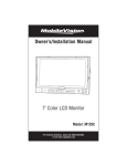
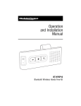
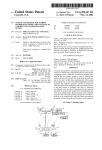
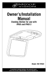
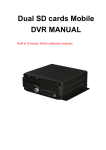
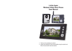
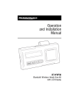
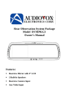
Owner’s/Installation Manual
-
+
MENU
CAM
MODE
POWER
7” Color LCD Monitor
Model: M135C-4
For Technical Assistance, please call (800) 638-3600,
or visit www.magnadyne.com
Table of Contents
Introduction............................................................................................................................... 2
Warning / Caution...................................................................................................................... 2
Monitor Features and Controls.................................................................................................. 3
Remote Control Functions......................................................................................................... 3
General Operation................................................................................................................... 4-5
Wiring Diagram ......................................................................................................................... 5
Installation Instructions............................................................................................................. 6
Technical Specifications............................................................................................................. 7
Warranty.................................................................................................................................... 8
Introduction
Congratulations on the purchase of a quality MobileVision 7” LCD Monitor. This system has
been designed to provide years of trouble free operation.
The information enclosed provides a quick reference of the operations and maintenance of the
new monitor.
This product must be installed and used in accordance with this manual. Any alterations to this
product that enables it to be used in any way other than intended or designed could distract the
driver and result in an accident causing injury or death. Magnadyne Corporation disclaims any
and all liability that may result from failure to install and operate in any other manner in which
this was intended.
Warning
Backing Up Your Vehicle
Do not backup your vehicle while looking at the monitor. Always look in the direction of your
vehicle’s motion. Use the monitor only as an aid in safety confirmation. The actual distance
may be different than it appears in the monitor. The range of the image in the monitor is limited. Always be aware that blind spots may exist and not appear at all times on your monitor.
The product is intended to assist in safe driving and allows the driver to have a broader field
of vision during backup. You, as the driver, are solely responsible for the safe operation of
your vehicle and the safety of your passengers and pedestrians, and for abiding of all state
and local traffic regulations. Do not use any features of this system to the extent it distracts
you from safe driving. Your first priority while driving should always be the safe operation
of your vehicle. MobileVision will not accept any responsibility whatsoever for accidents
and/or injuries resulting from failure to observe these precautions or safety instructions.
Caution
• FCC REGULATIONS STATE THAT ANY UNAUTHORIZED CHANGES OR MODIFICATIONS TO THIS
EQUIPMENT MAY VOID THE USER’S AUTHORITY TO OPERATE IT.
• TO REDUCE THE RISK OF FIRE OR ELECTRIC SHOCK, DO NOT EXPOSE THIS EQUIPMENT TO RAIN OR
MOISTURE.
• THIS DEVICE IS INTENDED FOR CONTINUOUS OPERATION.
• TO REDUCE THE RISK OF FIRE OR ELECTRIC SHOCK AND ANNOYING INTERFERENCE, USE ONLY THE
RECOMMENDED ACCESSORIES.
2
Monitor Features and Controls
-
+
MENU
CAM
MODE
POWER
2
3
4
5
1
1. Volume Buttons (- and +): Press to adjust
the speaker’s volume.
2. Menu Button: Press to access the monitor’s
adjustment features.
3. Camera Selection Button (CAM): Press to
select the desired camera view: Left, Right,
Front or Rear.
6
7
4. Camera Display Configuration Button
(MODE): Press to select different camera
display configurations.
5. Power Button: Press to turn the monitor
on or off.
6. IR Sensor: Receives signal from the
remote control.
7. Speaker
Remote Control Functions
1
4
MODE
5
2
3
MENU
CAM1
CAM2
CAM3
CAM4
1. Screen Display Selection Button (MODE):
Press to adjust the screen’s camera views.
2.
, , or Navigation Buttons: Press
these buttons to adjust the speaker’s volume or adjust the selected menu function.
CAM 1 = Left Side Camera
CAM 2 = Right Side Camera
CAM 3 = Front Camera
CAM 4 = Rear Camera
3. Camera(s) Display Configuration Button
(MODE): Press to select different camera
display configurations.
4. Power Button: Press to turn the screen on
or off.
5. Menu Button: Press to access the monitor’s
adjustment features.
3
General Operation
Turning the Monitor On:
The monitor is operational by activating the ignition
key then manually pressing the power switch on the
unit.
MENU
CAM
MODE
POWER
Selecting the Camera View
Press to select the desired camera view.
Note: When the camera is automatically selected (Example:
the vehicle is put into reverse) the camera image will
automatically override the selected camera image.
-
+
MENU
CAM
MODE
POWER
-
+
MENU
CAM
Adjusting the Speaker’s Volume
Press these buttons (- or +) to adjust the speaker’s
volume.
Configuring Monitor’s Camera Display
Press the MODE to select the desired camera display
configuration.
Note: When the camera is automatically selected (Example:
the vehicle is put into reverse) the camera image will
automatically override the selected camera display.
+
Camera
Display
Configurations
MENU
CAM
MODE
POWER
LEFT
RIGHT
FRONT
REAR
LEFT
FRONT
RIGHT
REAR
4
LEFT
RIGHT
FRONT
REAR
M
General Operation
Monitor Adjustment
To access the monitor adjustment features, press the
MENU button. Use the - or + buttons to make adjustments to the selected function.
Menu Functions:
• Brightness
• Contrast
• Saturation
• Hue
• Volume
• Language
• Rotating
• Rotating
• Mirror 1
• Mirror 2
• Mirror 3
• Mirror 4
• Reset
-
+
CAM
MENU
-
MODE
+
MENU
POWER
CAM
M
Wiring Diagram
Red Wire: 12 Volt Switched
Purple Wire: Trigger Camera 4 (Rear)
Black Wire: Ground
Yellow Wire: Trigger Camera 3 (Front)
Brown Wire: Trigger Camera 2 (Right Side)
Camera 3
Front View Camera
3
Camera 4
Rear View Camera
4
Camera 2
Right View Camera
2
Camera 1
Left View Camera
1
Green Wire: Trigger Camera 1 (Left Side)
5
Installation Instructions
Pedestal Mounting the Monitor
1. Loosen the thumb wheel on the base support so the nut attached to the thumb wheel
can slide into the monitor’s mounting channel.
2. Slide the thumb wheel nut into the channel on the back of the monitor.
3. Position the monitor to the desired height and tighten the base support thumb wheel.
4. Adjust the tilt knob.
5. Use the double-sided foam (supplied) or mounting screws (not supplied) to secure the base
support to the desired location.
Monitor’s
Mounting
Channel
Nut
Base Support
Thumb Screw
Tilt Knob
Double Sided
Mounting Foam
6
Technical Specifications
Display Size: 7-inch
Display Format: 16:9
System: PAL/NTSC
Power Supply: 12-32V
Power: 12W
Picture Resolution: 800x480
7
Warranty
ONE (1) YEAR LIMITED WARRANTY
Magnadyne Corporation or its authorized agents will within one year from the date of sale
to you, repair, replace or refund the retail sales price of said product or any part thereof, at
the option of the Magnadyne Corporation or its authorized agents, if said product or part
is found defective in materials or workmanship, when properly connected and operating
on the correct power requirements designated for the specific product. This warranty and
Magnadyne Corporation or its authorized agent’s obligations hereunder do not apply where
the product was; damaged while in the possession of the consumer, subjected to unreasonable or unintended use, not reasonably maintained, utilized in commercial or industrial
operations, or serviced by anyone other than Magnadyne Corporation or its authorized
agents, or where the warning seal on the product is broken or the power and/or plugs
are detached from the unit. Magnadyne Corporation or any of its authorized agents will
not assume any labor costs for the removal and reinstallation of any product found to be
defective, or the cost of transportation to Magnadyne Corporation or its authorized agents.
Such cost are the sole responsibility of the purchaser.
This warranty does not cover the cabinet appearance items or accessories used in connection with this product, or any damage to recording or recording tape, or any damage
to the products resulting from improper installation, alteration, accident, misuse, abuse or
acts of nature.
MAGNADYNE CORPORATION OR ITS AUTHORIZED AGENTS SHALL NOT BE LIABLE TO
ANYONE FOR CONSEQUENTIAL OR INCIDENTAL DAMAGES OR CLAIMS EXCEPT THOSE
ACCORDED BY LAW. NO EXPRESSED WARRANTY OR IMPLIED WARRANTY IS GIVEN
EXCEPT THOSE SET FORTH HEREIN. NO IMPLIED WARRANTY SHALL EXTEND BEYOND
ONE YEAR FROM THE DATE OF SALE.
This warranty extends only to the original purchaser of the product and is not
transferable. Some states do not allow limitations on how long an implied warranty lasts,
and some states do not allow the exclusion or limitation of incidental or consequential
damages, so the above limitations or exclusion may not apply to you. This warranty gives
you specific legal rights, and you may have other rights that vary from state to state.
“NOTE: The manufacturer is not responsible for any radio or TV interference caused by
unauthorized modifications to this equipment. Such modifications could void the User’s
authority to operate the equipment.”
Defective merchandise should be returned to the original point of purchase or
secondly, to Magnadyne Corporation, 1111 W. Victoria Street, Compton CA 90220.
Return Authorization must be obtained before sending, or merchandise may be refused.
Copyright © 2011 MobileVision
M135C-4-UM Rev. A 6-17-11