1
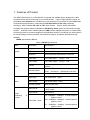
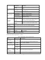
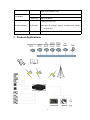
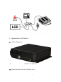
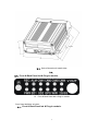
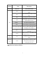
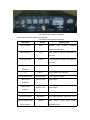
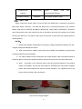
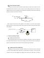
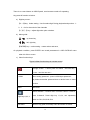
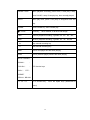
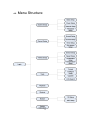
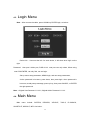
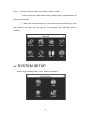
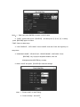
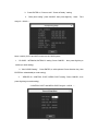
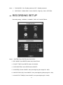
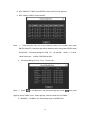
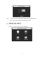
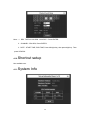
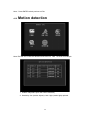
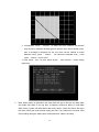
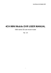
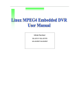
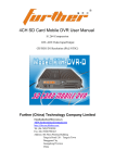
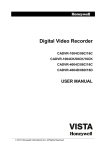
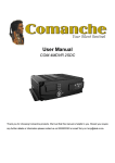
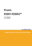
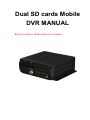
Dual SD cards Mobile
DVR MANUAL
Built-in G-sensor, Motion detection modules.
Contents
1.
2.
3.
4.
FEATURES OF PRODUCT………………………………………………………………….3
PRODUCT APPLICATIONS…………………………………………………………………6
APPEARANCE OF PRODUCT……………………………………………………………..7
DEVICE USER GUIDE…………………………… ………………………………………14
4.1. Remote control function………………………………………………………………14
4.2. Menu Structure……………………………………… … …………………………….17
4.3. Login Menu……………………………………… ……… …………………………..18
4.4. Main Menu……………………………… ……………… ……………………………18
4.5. System Setup………………………………
……… …………………………….19
4.6. Recording Setup
………………………………… … …………………………. 22
4.7. Vehicle Info
…………………………………………
……………………………24
4.8. Management Tools
………………………………
…………………………….26
4.9. Playback Menu
………………………………………
…………………………..28
4.10.Shortcut setup…………………………………………… …………………………….29
4.11. System Info
……………………………………………
…………………………31
4.12 Motion Detection…………………………………………
……………………………32
2
1. Features of Product
The MDVR (Automotive) is a cost-effective, functional and scalable device designed for video
surveillance and remote monitoring of your mobile assets. It uses a high-speed processor, an
embedded Linux platform and combines the most advanced IT processes such as H.264 Video
Compression/Decompression, networking and GPS(excluded in this unit) positioning
technology. MDVR enables CIF, HD1 and D1 video formats. Drivers' driving information,
recording and wireless data are uploaded to SD Memory Cards which are used as the storage
medium. A MDVR centric software platform (CMS) can be realized with links to a Central Alarm
monitoring system for remote management and playback analysis. The MDVR may look simple in
its exterior design, provides powerful auto black box features, installation flexibility and high
reliability.
MDVR Specifications Blank 1。
Blank 1 MDVR Specifications
Items
System
Parameters
Specifications
Language
Chinese/English
OSD
Graphical User interface(OSD menu)
Password
Users Password/ Administrator Password
Video input
4-CH video input
1.0Vp-p,75Ω
Video output
1-CH video output
1.0Vp-p,75Ω
Preview
Vision
Recording Ratio
Audio
Image
processing
storage
Support 1 channel or synchronous 4 channels
preview.
PAL 25 Frame/s CCIR625 line, 50 field
NTSC
30 Frame/s
CCIR525 line, 60 field
Image Compression
H.264 Main profile, 75fps D1/s
Audio input
4-ch Audio input
Audio output
1-ch Audio output
Recording mode
Audio & Video sync.
Video format
4-ch CIF: 25fps, 4-ch HD1: 25fps, 2D1: 25fps
+ 2CIF: 25fps,
Video stream
ISO14496-10
Video Rate(kbps)
CIF: 1536Kbps ~ 128Kbps,8 levels optional.
Highest:1 level
HD1: 2048Kbps ~ 380Kbps,8 levels optional.
Highest:1 level
D1: 2048Kbps ~ 400Kbps,8 levels optional.
Highest:1 level
&
3
600Ω
600Ω
Alarm
Communication
Port
Audio Bitrate
4Kbytes/s
Storage
Support Dual SD card storage, 32GB for
each.
Alarm input
6 alarm input, No alarm below 4V, high level
alarm above 4V.
Alarm output
2 alarm output, high level 12V output.
Serial Interface
Support 1-RS232 interface
Serial Interface
Support 2-RS485 interface
WIFI
Interface(excluded)
Support 802.11b/g
Auto Station reporter Support connecting Auto Station Reporter or
control panel via extended interface
Interface
Extended
interface
Audio
amplifier
power
Support 2-ch audio power amplifier output
GPS(excluded in
this unit)
GPS module(excluded in the unit), Geographic co-ordinates, speed
can be read in coding flow, and can be wireless uploaded.
Motion detection
Yes
Acceleration
Built in acceleration G-Sensor
Software
Analysis
playback
Upgrade
Support SD cards upgrade.
of
PC
Video playback on PC,and analyse the vehicle
info in the file.
MDVR basic electrical Specifications
blank 2。
Blank 2 MDVR basic electrical Specifications
Items
Parameters
Specifications
+ 8V ~ + 36V, When long-term under 8V, or long-term
Power input
8—36V
over 36V, Auto power off, ENTER protected mode.
Power output
12V
12V(+/-0.2V),Max:2A.
≤4V
OFF。
≥5V
ON。
75Ω
75Ω for each video input impedance
Vehicle key signal
Video
input
impedance
Video output Volt
2Vp-p
Input 2Vp-p CVBS analog signal, reveal device input
4
need 75Ω impedance to fit
0—4V
Low level alarm
I/O interface
Above 4V
High level alarm。
1.32GB for each card.
SD-card interface
2 SD cards
2.SD-card for storage, support recording and system
upgrade, etc.
Operating Temp
-40℃-80℃
Under well-ventilated enviroment.
2. Product Applications
5
3. Appearance of Product
3.1. Device Appearance
1.1
MDVR Device Appearance
3.2. Device drawing Dimension & Install Holes
6
3.3. Device Dimension & Install Holes
3.4.
3.5. Front & Back Panel led & Plug-in module.
1.2
Front & Back Panel led & Plug-in module.
Front Panel definition as below:
3.1. Front & Back Panel led & Plug-in module.
7
Interface
VIDEO-OUT
Items
Description
VIDEO-OUT
Video Simulation output
SD1 card recording led, light on as SD1
SD1
exist.
SD1 card recording led, light on as SD2
SD2
exist.
REC
Recording led,light on as recording
GPS signal led,light on as GPS module
GPS
LED
exist(excluded in the unit).
POWER
Led, Light on as power normal
ALM
ALM LED, light on as device abnormal
Light on as CAM1/CAM2/CAM3/CAM4
CAM1/CAM2/CAM3/CAM4
has signal, or else, no light on
Light on as WIFI module exist (excluded
WIFI
in this unit)
Light on as 2G / 3G module exist
2G/3G
(excluded in this unit)
IR
receiver
IR receiver, receive remote control
IR
During working, open key lock, system
Electronic
Lock
signal
LOCK
will load-off 2-SD cards, load-on
recording after 1min auto.
3.2. Back Panel interface definition
8
Pic 8 Back Panel interface definition
Back Panel interface definition as followed:
Pic 8 Back Panel interface definition
Interface
WIFI interface
Items
Description
WIFI
Wireless
LAN
antenna
interface
(excluded in this unit)
GPS interface
GPS
GPS antenna interface (excluded in
this unit)
2G/3G interface
2G/3G
2G/3G antenna interface (excluded in
this unit)
Power input
DC8-36V
Power input interface
interface
LPT
MCU
System adjust info interface
Extended interface
EXTENTION
Control panel interface
Video output
VIDEO- OUT
Video output
AUDIO- OUT
Audio output
interface
Audio output
interface
CAN-BUS interface
CAN-BUS
Vehicle electronic control network
Sensors interface
SENSORS
Swich input interface,high level(>4V)
Vehicle speed pulse
SPEED
Input vehicle speed pulse signal,
input interface
differential input
9
RS485/RS232
RS485/RS232
RS232
interface
Speaker interface
/
RS485
serial
data
communication interface
SPEAKER
Audio power amplifier output
3.3. Power Cable
Figure 8 shows the power cable, one end is 6Pin with White Plug, connected to the device
panel 6Pin White Connector. The Red and Black wire is connected directed to the vehicle's
battery. Red wire is POSITIVE and Black is NEGATIVE. Yellow cable is FIREWIRE. The device
which be turned on when the vehicle's key are in the ignition and turns off or delay turn off when
the keys are taken out. The yellow cable connects the point of panel lamp key opened (point of
vehicle ignition).
NOTES:
1)Please verify battery voltage before connecting. Voltage accepted is between 12V-36V.
A higher voltage will damage the device.
2 ) After connecting the cables, ensure that power cables are insulated to prevent short
circuiting and burning out the battery.
3)The Yellow cable must be connected to the vehicle ignition cable, otherwise the device
will not be able to execute the delayed shutdown and the final moment of the video will be lost.
4)Note:
Connection to the vehicle's engine must be connected directly to the positive
anode of the battery. Do Not Use bond strap for grounding as it will produce negative
pulses that would interfere the device's normal operation. The negative pole of the
power code must be Φ1.5mm and above.
PIC10 Power Supply Diagram
10
3.4. Alarm input and output
The device has 6 alarm input and 2 alarm output interfaces. Various state of alarm level can
be detected while the vehicle is in motion. Action`s such as braking, steering horn etc. Below is a
diagram that shows when the braking vane Is depressed, the MDVR would be able to detect the
high level, otherwise, just detect the low level.
+24V
Braking vane
Stoplight
lissihohao
Connect
MDVR
sensor input cable
Alarm outputs are level output drive capability for the 200MA, if you want to drive relatively
large power device, must be external relay. Shown below is the Alarm output photoelectric alarm
wiring diagram.
MDVR ALM output
1.6
24V
Device Installation Guide
A. Inspecting the Accessories
After unpacking, please check the device for damage or deformation. If there are, please do
not install the device and get in touch with the supplier. In the product box there is a packing list.
Please cross check this list with the device and its accompanying accessories.
B. Installing the SD and SIM Card
SD cards are on the main board, insert SD1 & SD2 from the front board of device. SIM card
is on the communication board, take down the small shield of the device. You can see SIM
interface. Insert it into clip (Negative up). When system supports 3G, then there is a need to
11
install SIM card.
*NOTED: PLS DO NOT LOCK WHEN THE SD SLOT IS OPEN, OR ELSE, THE LOCK
WILL BE DEMAGED.
12
4. DEVICE USER GUIDE
4.1.
Remote control function
13
There is no control button on MDVR panel, need remote control to fit operating.
Key-press & function as below:
a) Digit keys zone:
【0-9】key:Under setting,Use for select digit. During playback and preview,1、
2、3、4 is for the switch of the channels
【+】、【-】key:adjust digit when plus or deduct.
b) Menu guide:
,
: up, down key;
,
: left, right key;
【ENTER】key:under setting,means select and save.;
On playback condition, press ENTER can reveal parameters in OSD OVERLAY menu
when it’s ON on screen.
c) Other function keys:
Figure 8 Other function keys on remote control
Through screen , 2 times press for reboot ( soft start key )
(note:can’t be use now)
LOGIN
When setting password,press LOGIN input password。
Do please remember password due to device have no reset
function.
INFO
Check info
Switch between 1-channel and 4-channel version. Press it,
Digit keys1,2,3,4
show 4-channel. Press digit key 1,2,3,4, can separately
switch to CH1,CH2,CH3,CH4
RETURN
Return to up grade, exit setup menu and return to screen.
14
PAUSE / STEP
When playback recording, press STEP, a time play a step,
press PAUSE, it stop. Press play key, then normally played.
GOTO
When play back, press it can jump to designated time and
play.
FRAME
Press FRAME key, then FRAME play.
PLAY key, (when PAUSE, it will show still image)
(PLAY)
FWD
FWD for playback recording, 4 grades: 2X,4X,8X,16X
REW
REW for playback recording, 4 grades: 2X,4X,8X,16X
■
Stop manual recording key
●
Start manual recording key
NEXT
Turn to next page/ next file when playing.
PREV
Turn to previous page/ previous file when playing
AUTO、PRESET、
ZOOM+/-
、
FOCUS+/-
、
PTZ function keys
IRIS+/- 、 PTZ 、
PRESET
、
RECALL、BRUSH
F1、F2、F3
F1 is shortcut key , F2,F3 are Spare keys. (Reserved for
future)
15
4.2.
Menu Structure
16
4.3.
Login Menu
Note:After connect the cable, press LOGIN key ENTER login, as below::
Device No. :Users set the NO. for each device, it will show when login on the
right.
Password:User psw / Admin psw, PWD:111111. user psw can only select, When using
user PSW ENTER, can only find, can not login.
Set-up menu setup parameter, ADMIN login, and can setup parameters,
As the password is incorrect, press down, then press login. when password is
incorrect, reveal prompt message, press up key, then press CANCEL, re-ENTER
the right password.
Note:Original User Password: 111111, Original Admin Password: 111111.
4.4.
Main Menu
Main menu
include: SYSTEM,
RECORD, VEHICLE, TOOLS, PLAYBACK,
SHORTCUT, MODULE, INFO. As below:
17
Note:1、All of the submenu setup, must SAVE, or else not valid.
2、When check box is filled denotes select certain function, unfilled denotes not
select certain function.
3、Digit input can follow digit key on the remote control input directly or using
soft keyboard, the letter must be input by soft keyboard, press RETURN back to
submenu.
4.5.
SYSTEM SETUP
System setup including: Basic, Power, Network, Password.
18
Note:1.Date type: press ENTER for switch Y-M-D/ D-M-N.
2."DATE": system date, press 【ENTER】 , and then press【-】or【+】 to setup,
press【ENTER】again to confirm.
"TIME": Same as date setup.
3. "OPR TIMEOUT", "DEV NUM": Press CANCEL and then Press the digit keys to
setup them.
4. "COMPANY NAME", "VEHICLE NO", "DRIVER NAME",”LINE NUM”: Press
【ENTER】 key to pop out keyboard window, then use
left/right/up/down/ENTER key to setup.
5. Select “SAVE” and press 【ENTER】to save the settings.
Note:1. "Power mode": on and Timing。
2. ‘’Power off delay’’: ACC/OFF。
19
3.Press ENTER on "Power mode" ‘’Power off delay’’ setting.
4.’’Delay time setting’’ press CANCEL then press digit key(Note:Time
range:3—120min)。
Note: It mainly for 3G and WIFI connect to the CMS system
1.’’IP ADDR、NETMASK,GATEWAY” setting: Press CANCEL,then press digit key to
switch(no need setting).
2.’’MAC ADDR Setting’’
Press ENTER, to soft keyboard. Press direction key, then
ENTER the related add(no need setting).
3 . ’’ SERVER IP, CONTROL PORT, MEDIA PORT setting: Press CANCEL, then
press digit key(no need setting).
(CONTROL PORT and MEDIA PORT range 0—65535 )。
20
Note:1、"PASSWORD": ON---Enable password; OFF---Disable password.
2、”USER PSW’’ “ADMIN PSW”: Press CANCEL—Digit key—Save—RETURN。
4.6.
RECORDING SETUP
Recording setting:NORMAL, CHANNEL, TIME LIST, SUB-STREAM。
Note:1.SYSTEM: Press ENTER select PAL/NTSC。
2.REC MODE: Press ENTER select Auto/ Alarm/Timed.
3.PACKET TIME: Press ENTER select 15/30/45/60。
4.OVER WRITTEN: Press ENTER select ON/OFF。
5.ALM PRE(S): Press CANCEL, then press digit key (time range 0S-- 60S).
6.ALM REC DELAY(S): Press CANCEL, then press digit key (delay range 30—900).
7.ALM OUTPUT TIME(S): Press CANCEL, then press digit key(5S---240S).
21
8.REC PROTECT TIME: Press ENTER, select 1/3/5/7/10/15 optional.
9.REC VEHICLE INFO: Press ON/OFF.
Note : 1 、 Press Direction key set up the Channel, select CH1 Enable, then press
ENTER-ON/OFF, Press right key select resolution ratio, then press ENTER select
D1/HD1/CIF。The same settings for FRM(01----30 optional), QUAL(1---8 level,
1level is the best), AUDIO, PREVIEW as Res.
2、The same setting for CH2、CH3、CH4 as CH1。
Note:1.Press
in the digit zoon, and then press digit key, press
digit key set up TIME1 in turn. Press right key, with the same step for TIME2.
2.MONDAY----SUNDAY, the same setup steps as EVERYDAY.
22
, then press
Note:1.Bit rate setting:16/24/32/40/48/56/64/72/80/96/128/160/200/256/384 optional.
2.Frame setting 01/02/03/04/05/07/10/13/15/20/23/25 optional。
4.7.
VEHICLE INFO
Vehicle info:Sensor, Speed, Accelerate, Temperature
23
Note:1.Press ENTER, then press CANCEL can modify the Name, such as setting
icon is on the F-DOOR Enable, pls press ENTER select ON/OFF, Press right
select PW LEVEL, press ENTER, select HIGH/LOW level.
2.The same setting with R-DOOR、BRAKE、LEFT、RIGHT Enable、PW
LEVEL、RECORD、ALM as F-DOOR。
Note:1.SPD SOURDE: GPS/VEHICLE,Press ENTER to switch。
2.SPD ADJUST: Press CANCEL,then press digit key。P/S: Press CANCEL,
then press digit key。
3.SPD UNIT: KM/MPH, Press ENTER for switch.
4.Low speed ALM Enable: press ENTER, select ON/OFF;then press right key,
24
press CANCE, then press digit key set up Threshold, press right key,
then press ENTER set up the Record ON/OFF.
5.High speed ALM Enable: the same setting as low speed ALM Enable.
Note: 1.X setting: Press Direction key, making the setting on the X enable , then
press ENTER—select ON/OFF; press right, then press CANCEL, then
press digit key set up the Threshold, press right, then press
ENTER---select ON/OFF.
2.Y、Z: the same setting as X。
4.8.
MANAGEMENT TOOLS
Management tools:Format、Configuration、Upgrade、Log。
25
Note : Press ENTER select SD1/SD2, then press right key, press ENTER select
format or not.
Warning:Format will lost all the data in the device. For sure, press FORMAT. Or else,
press CANCEL.
Note:Press down key for Reset settings,then press ENTER,system remind message。
For sure to reset, press ENTER. Or else, select EXIT.
26
Note: System upgrade including: file system, application, Press ENTER 。
Note: Press direction key select START TIME, END TIME, then press digit key setting.
4.9.
PLAYBACK MENU
27
Note:1.REC TYPE:ALL/ALARM(ALM REC)Press ENTER。
2.CHANNEL: SD1/SD2, Press ENTER。
3.DATE、START TIME, END TIME, Press left/right key, then press digit key. Then
press SEARCH.
4.10.
Shortcut setup
Not available now.
4.11.
System Info
28
Note:Press ENTER switch previous or Exit.
4.12
Motion detection
Note: ENTER Tool. Press the detection and ENTER it. Take 1 channel for example.
1. Enable: ON(means open the motion detection)
2. Sensitivity: low (motion objects) / mid / high (motion light) optional.
29
3. configuration: Press " ENTER " to select the zoom interface via direction
key( the zoom marked to be dark green if selected, then select another zoom,
then a rectangle of diagonal for the two zoom will be marked a motion
detection zoom, press " Cancel " can cancel the selected zoom, ), then
press "Return"to tool menu.
4. Save: press"Yes"on save. When shows "save success"means setting
implement.
5.
Note: When motion is detected in the area within the gird, it will give out alarm data,
and marks MD alarm in the log files, if happens continuous alarm or multi-alarm
within 30sec, system will write alarm data every 30sec. Users can search the log in
the tools. During the record period setting via user, if any alarms are received, all of
the recording during the setting time will be packed to a alarm recording.
30
REMARK
APPLICATION:
Our Mobile DVR can be used for Buses, cars, coaches, cash carriers, industrial
vehicles, taxi, investigation vehicles, military trucks, police vehicles, ambulances,
Tourism buses, even yachts, aircraft and vessels. It can also be used in farm,
construction site, vacation spot to monitor the around environment if nobody nearby,
etc.
Package Including:
1X unit
1X remote control
1X CD(manual and PC view S/W)
1X Hex wrench
2X Batteries for remote control
1X sensor cable
1X power cable
4X camera cables
1X GPS module (excluded), charged additional
1X 3G module (excluded), charged additional
1X WIFI module (excluded), charged additional
CMS software (optional) charged additional
Control panel (optional), charged additional
31