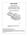
1
DYNA-GLASTM CENTRIFUGAL PUMPS
WITH INTEGRAL TRAP
O
W
N
E
R’
S
M
A
N
U
A
L
INSTALLATION, OPERATION & PARTS
5MPRA Series MODELS
5MPRA6C-146
5MPRA6D-147
5MPRA6E-148
5MPRA6F-156
5MPRA6C3-146
5MPRA6D3-147
5MPRA6E3-148
5MPRA6F3-156
This manual should be furnished to
the end user of this pump; its use will
reduce service calls and chance of
injury and will lengthen pump life.
STA-RITE FOREIGN SALES CORP.
175 WRIGHT STREET, DELAVAN, WISCONSIN 53115 USA
Telephone: (414) 728-5551; Telefax: (414) 728-4461
Cable: STAREX; Telex: (ITT) 4970245
© 1994, Sta-Rite Industries, Inc.
Printed in U.S.A.
S289 (Rev. 3/17/94)
‘5MPRA’ SERIES PUMP WITH TRAP
To avoid unneeded service calls, prevent possible injuries, and get the most
out of your pump, READ THIS MANUAL CAREFULLY!
The Sta-Rite ‘5MPRA’ Series Self-priming Centrifugal pump:
• Is designed for use with swimming pools or as a centrifugal pump.
• Is an excellent performer; durable, reliable.
Table of Contents
Warranty.......................................................................................................2
Safety Instructions ........................................................................................3
Installation ....................................................................................................4
Electrical....................................................................................................5-6
Operation .....................................................................................................7
Storage/Winterizing ...................................................................................7-8
Pump Service...........................................................................................9-10
Troubleshooting Guide ...............................................................................11
Repair Parts List ..........................................................................................12
LIMITED WARRANTY
Pumps, filters, spa systems, skimmers, underwater lights (except bulbs), accessories and fittings manufactured by Sta-Rite are warranted to be free of defects in material and workmanship for one (1) year from date of installation.
HRPB, DEPB and System 3 are warranted against defects in material and workmanship for a period of ten (10) years from date
of installation. Internal filter components and valves are warranted for a period of one (1) year from date of installation.
The foregoing warranties relate to the original consumer purchaser (“Purchaser”) only. Sta-Rite shall have the option to repair
or replace the defective product, at its sole discretion. Purchasers must pay all labor and shipping charges necessary to replace
the product covered by this warranty. Requests for warranty service must be made through the installing dealer. This warranty
shall not apply to any product that has been subject to negligence, misapplication, improper installation or maintenance, or other
circumstances which are not in Sta-Rite’s direct control.
This warranty sets forth Sta-Rite’s sole obligation and Purchaser’s exclusive remedy for defective products.
STA-RITE SHALL NOT BE LIABLE FOR ANY CONSEQUENTIAL, INCIDENTAL OR CONTINGENT DAMAGES WHATSOEVER.
THE FOREGOING WARRANTIES ARE EXCLUSIVE AND IN LIEU OF ALL OTHER EXPRESS WARRANTIES. IMPLIED WARRANTIES, INCLUDING BUT NOT LIMITED TO THE IMPLIED WARRANTIES OF MERCHANTABILITY AND FITNESS FOR A
PARTICULAR PURPOSE, SHALL NOT EXTEND BEYOND THE DURATION OF THE APPLICABLE EXPRESS WARRANTIES PROVIDED HEREIN.
Some states do not allow the exclusion or limitation of incidental or consequential damages or limitations on how long an implied warranty lasts, so the above limitations or exclusion may not apply to you. This warranty gives you specific legal rights and
you may also have other rights which vary from state to state.
Supersedes all previous publications.
Sta-Rite Industries, Inc., 600 S. Jefferson St., Waterford, WI 53185
2
IMPORTANT
SAFETY
INSTRUCTIONS
Always follow basic safety precautions with this equipment, including the following.
To reduce the risk of
injury, do not permit children to
use this product unless they are
closely supervised at all times.
This pump is for use
with permanently installed pools
and may also be used with hot
tubs and spas if so marked. Do
not use with storable pools. A
permanently installed pool is constructed in or on the ground or in
a building such that it cannot be
readily disassembled for storage.
A storable pool is constructed so
that it may be readily disassembled for storage and reassembled
to its original integrity.
SAVE THESE
INSTRUCTIONS
READ AND FOLLOW ALL
INSTRUCTIONS!
This is the safety alert symbol. When you see this symbol on your system
or in this manual, look for one of the following signal words and be alert
to the potential for personal injury.
warns about hazards that will cause death, serious personal
injury, or major property damage if ignored.
warns about hazards that can cause death, serious personal
injury, or major property damage if ignored.
warns about hazards that will or can cause minor personal injury
or property damage if ignored.
NOTICE indicates special instructions not related to hazards.
Carefully read and follow all safety instructions in this manual and on equipment. Keep safety labels in good condition; replace if missing or damaged.
Incorrectly installed or tested equipment may fail, causing
severe injury or property damage.
Read and follow instructions in owner's manual when installing
and operating equipment. Have a trained pool professional perform all pressure tests.
1. Do not connect system to a high pressure or city water system.
2. Use equipment only in a pool or spa installation.
3. Trapped air in system can cause explosion. BE SURE all air is out of system
before operating or testing equipment.
Before pressure testing, make the following safety checks:
•
•
•
•
•
•
Check all clamps, bolts, lids, and system accessories before testing.
Release all air in system before testing.
Tighten Sta-Rite trap lids to 30 ft. lbs. (4.1 kg-m) torque for testing.
Water pressure for test must be less than 25 PSI (7.5 kg/cm2).
Water Temperature for test must be less than 100o F. (38o C).
Limit test to 24 hours. After test, visually check system to be sure it is ready
for operation. Remove trap lid and retighten hand tight only.
NOTICE: These parameters apply to Sta-Rite equipment only. For
non-Sta-Rite equipment, consult manufacturer.
3
DISCHARGE PORT
TO FILTER OR POOL
NOTICE: Port threads
are: Internal - 2" NPT
for direct connection to
pipe. External - 3-1/4"
Buttress. Fits Sta-Rite
U11-200P Union Half
for quick disconnect
pipe connection.
STRAINER BASKET
COVER
SUCTION
PORT
FROM
POOL
OR
VACUUM
FILTERS
Figure 1
PUMP MAY BE BOLTED TO LEVEL
FOUNDATION OR MOUNTING BRACKET
INSTALLATION
Only qualified, licensed personnel should install pump and wiring.
Pump mount must:
Be solid - Level - Rigid - Vibration free. (To reduce vibration and pipe stress,
bolt pump to mount.)
Allow pump suction inlet height to be as close to water level as possible.
Pump will not lift water more than 10'(3m).
Allow use of short, direct suction pipe (To reduce friction losses).
Allow for gate valves in suction and discharge piping.
Have adequate floor drainage to prevent flooding.
Be protected from excess moisture.
Allow adequate access for servicing pump and piping.
NOTICE: When connecting threaded pipe directly to pump, use Teflon tape
or Plasto-Joint Stik1 to seal connections. Do not use pipe dope; pipe dope
causes cracking in some plastics and may damage components in piping system.
When connecting pipe to pump with union half, use Teflon tape or PlastoJoint Stik between pipe and union adapter. Union collar to pump should be
assembled dry and hand-tight.
NOTICE: Pump suction and discharge connections have molded in thread
stops. DO NOT try to screw pipe in beyond these stops.
Teflon Taping Instructions:
Use only new or clean PVC pipe fittings.
Wrap male pipe threads with one to two layers of Teflon tape. Cover entire
threaded portion of pipe.
Do not overtighten or tighten past thread stop in pump port!
If leaks occur, remove pipe, clean off old tape, rewrap with one to two additional layers of tape and remake the connection.
NOTICE: Support all piping connected with pump!
1
Lake Chemical Co., Chicago, Illinois
4
Piping:
Use at least 1-1/2" (38mm) pipe (use 2"(51mm) pipe if possible). Increase size
if a long run is needed. When using 1-1/2" pipe, connect to pump with 1-1/2"
to 2" (38 to 51mm) reducing adapter.
To avoid strains on the pump, support both suction and discharge pipes independently. Place these supports near the pump.
To avoid a strain left by a gap at the last connection, start all piping at the
pump and run pipe away from the pump.
To avoid airlocking, slope suction pipe slightly upward toward the pump.
NOTICE: To prevent flooding when removing pump for service, all flooded
suction systems must have gate valves in suction and discharge pipes.
Fittings:
Fittings restrict flow; for best efficiency use fewest possible fittings.
Avoid fittings which could cause an air trap.
Pool fittings must conform to International Association of Plumbing and
Mechanical Officials (IAPMO) standards.
Use only non-entrapping suction fitting or double suction.
TABLE I - RECOMMENDED FUSING AND WIRING DATA
Serv. to Motor - Dist. in Ft. (M)
Motor
HP
Branch Fuse
Rating Amps*
Max Load
Amps
Voltage/
Hz/Phase
0-100'
(0-30)
101-200'
(30-60)
201-300'
(60-90)
1/2
3/4
1
1-1/2
15
20
20
30
8.5
11.4
14.0
16.6
115/50/1
115/50/1
115/50/1
115/50/1
2.0
2.5
2.5
4.0
2.0
4.0
4.0
6.0
2.5
6.0
6.0
10.0
1/2
3/4
1
1-1/2
15
15
15
15
4.25
5.7
7.0
8.3
230/50/1
230/50/1
230/50/1
230/50/1
2.0
2.0
2.0
2.0
2.0
2.0
2.0
2.0
2.0
2.0
2.0
2.0
1/2
3/4
1
1-1/2
15
15
15
15
2.51
3.38
3.66
4.8
230/50/3
230/50/3
230/50/3
230/50/3
2.0
2.0
2.0
2.0
2.0
2.0
2.0
2.0
2.0
2.0
2.0
2.0
1/2
3/4
1
1-1/2
15
15
15
15
1.45
2.0
1.83
2.8
380/50/3
380/50/3
380/50/3
380/50/3
2.0
2.0
2.0
2.0
2.0
2.0
2.0
2.0
2.0
2.0
2.0
2.0
* Time delay fuses are recommended instead of standard fuses in any motor circuit.
5
}
Metric
Wire
Size
(MM2)
ELECTRICAL
Ground motor before connecting to electrical power supply. Failure to
ground motor can cause severe or fatal electrical shock hazard.
Do not ground to a gas supply line.
To avoid dangerous or fatal electrical shock, turn OFF power to motor
before working on electrical connections.
Ground Fault Circuit Interrupter (GFCI) tripping indicates an electrical
problem. If GFCI trips and will not reset, have a qualified electrician
inspect and repair electrical system.
Hazardous voltage.
Can shock, burn,
or cause death.
Exactly match supply voltage to nameplate voltage. Incorrect voltage
can cause fire or seriously damage motor and voids warranty. If in
doubt consult a licensed electrician.
Ground pump before
connecting to
power supply.
Voltage
BONDING
LUG
Voltage at motor must be not more than 10% above or below motor nameplate rated voltage or motor may overheat, causing overload tripping and reduced component life. If voltage is less than 90% or more than 110% of rated
voltage when motor is running at full load, consult power company.
Grounding/Bonding
GREEN
GROUND
SCREW
Figure 2 – Typical ground screw and
bonding lug locations.
Install, ground, bond and wire motor according to local or National Electrical
Code requirements.
Permanently ground motor. Use green ground terminal provided under motor
canopy or access plate (See Fig. 2); use size and type wire required by code.
Connect motor ground terminal to electrical service ground.
Bond motor to pool structure. Use a solid copper conductor, size No. 8 AWG
(8.4 sq.mm) or larger. Run wire from external bonding lug (see FIg. 2) to reinforcing rod or mesh.
Connect a No. 8 AWG (8.4 sq.mm) solid copper bonding wire to the pressure
wire connector provided on the motor housing and to all metal parts of the
swimming pool, spa, or hot tub and to all electrical equipment, metal piping
or conduit within 5 feet (1.5 m) of the inside walls of swimming pool, spa, or
hot tub.
L2
115
VOLT
LINES
B
WHITE W/
BLACK TRACER
A
L1
BLACK
WHITE W/
BLACK TRACER
BLACK
L2
230
VOLT
LINES
B
Wiring
Pump must be permanently connected to circuit; be sure no other lights or appliances are on the same circuit. Match wire sizes to Table I (Pg. 5).
NOTICE: To prevent dirt, rain, bugs, etc., from entering motor when not
wiring with conduit, be sure to seal wire opening on end of motor.
Use Ground Fault Circuit Interrupter (GFCI) as master on-off switch; it will
sense a short circuit to ground and disconnect power before it becomes dangerous to pool users. Test according to maker’s instructions.
In case of power outage, check GFCI for tripping (which will prevent normal
water circulation). Reset if necessary.
A
L1
Figure 3 – Wiring hook-up diagram
Single Phase
6
OPERATION
NOTICE: NEVER run pump dry. Running pump dry may damage seals, causing leakage and flooding. Fill pump with water before starting motor.
Before removing trap cover:
1. STOP PUMP before proceeding.
2. CLOSE GATE VALVES in suction and discharge pipes.
3. RELEASE ALL PRESSURE from pump and piping system.
If pump is being pressure tested, be sure pressure has been released before removing trap cover.
Do not block pump suction. To do so with body may cause severe or
fatal injury. Small children using pool must ALWAYS have close adult
supervision.
Priming Pump
Hazardous suction.
Can trap hair or
body parts, causing
severe injury
or death.
Do not block
suction.
TO REMOVE
OVERTIGHT
LID
Release all air from filter and piping system: see filter owner’s manual.
In a flooded suction system (water source higher than pump), pump will prime
itself when suction and discharge valves are opened.
If pump is not in a flooded suction system, unscrew and remove trap cover
(see Figure 4); fill trap and pump with water.
NOTICE: Lubricate trap cover “O” Ring with petroleum jelly each time it is removed.
Clean and inspect “O” Ring; reinstall on trap cover.
Replace trap cover on trap; turn clockwise to tighten cover.
NOTICE: Tighten trap cover by hand only (no wrenches)!
Pump should prime now. Priming time will depend on vertical length of suction lift and horizontal length of suction piping.
If pump does not prime, make sure that all valves are open, suction pipe end
is under water, pump is not trying to lift water more than 10'(3m), and that
there are no leaks in suction pipe. See Troubleshooting Guide, Pages 10 and
11.
BOARD
Figure 4 – Use a pry bar or board as
shown to remove tight lid.
Storage/Winterizing:
NOTICE: Allowing pump to freeze will damage pump and void warranty!
NOTICE: Do not use anti-freeze solutions (except propylene glycol) in your
pool/spa system. Propylene glycol is non-toxic and will not damage plastic
system components; other anti-freezes are highly toxic and may damage plastic components in the system.
7
Drain all water from pump and piping when expecting freezing temperatures
or when storing pump for a long time (see instructions below).
Keep motor dry and covered during storage.
To avoid condensation/corrosion problems, do not cover pump with plastic.
For outdoor/unprotected installations:
1. Enclose entire system in a weatherproof enclosure.
2. To avoid condensation/corrosion damage, allow ventilation; do not wrap
system in plastic.
3. Use a 40% propylene glycol/60% water solution to protect pump to -50°F
(-46°C).
Draining Pump
1. Pump down water level below all inlets to the pool.
To avoid dangerous or fatal electrical shock hazard, turn OFF power to
motor before draining pump.
2. Remove trap cover and use low pressure air to blow accumulated water
from the piping system. Use a pry bar or board to remove trap covers that
have been overtightened or have taken a set and cannot be removed by
hand. Lugs have been provided on the trap lid to use a lever or pry bar for
loosening (see Figure 5).
3. Cap inlet piping after draining to keep water out of the pipes.
Hazardous voltage.
Can shock, burn,
or cause death.
Disconnect power
before working
on pump or motor.
4. To prevent pump from freezing, remove trap cover and drain the tank body
through the two drain plugs provided. Clean pump thoroughly; replace trap
cover.
NOTICE: Tighten trap cover by hand only (no wrenches)! If pump is not
anchored, use caution to not break attached piping!
5. Be sure motor is kept dry and covered.
Startup For Winterized Equipment
1. Remove any temporary weather protection placed around system for shutdown.
2. Follow filter manufacturer’s instructions for reactivation of the filter.
3. Inspect all electrical wiring for damage or deterioration over the shutdown
period. Have a qualified serviceman repair wiring as needed.
TO REMOVE
OVERTIGHT
LID
4. Inspect and tighten all watertight connections.
BOARD
Figure 5 – Use a pry bar or board as
shown to remove tight lid.
5. Open all valves in suction and return piping.
6. Remove any winterizing plugs in piping system.
7. Drain all antifreeze from system.
8. Close all drain valves and replace all drain plugs in piping system.
9. Prime pump according to instructions on Page 7.
8
PUMP SERVICE
Pump should only be serviced by qualified personnel.
Be sure to prime pump (Pg. 7) before starting.
Before removing trap cover:
1. STOP PUMP before proceeding.
2. CLOSE GATE VALVES in suction and discharge pipes.
3. RELEASE ALL PRESSURE from pump and piping system.
To avoid dangerous or fatal electrical shock hazard, turn OFF power to
motor before working on pump or motor.
Aside from lubricating trap cover “O” Ring, no lubrication or regular maintenance is needed beyond reasonable care and periodic cleaning of strainer
basket.
If shaft seal is worn or damaged, repair as follows:
Pump Dissasembly/Removing Old Seal
Disconnect power to pump motor.
Hazardous voltage.
Can shock, burn,
or cause death.
Disconnect power
before working
on pump or motor.
Be sure gate valves on suction and return piping are closed before starting work.
Release all pressure by opening all vents before starting work.
1. Drain pump by removing drain plugs on bottom of pump body and trap
body.
2. Be sure there is no pressure in trap body; remove cover (unscrew by turning counterclockwise).
3. Remove 6 nuts, lockwashers and flat washers holding seal plate to pump
body. Pull seal plate and motor away from pump body. (You may have to
CAREFULLY use a screwdriver to separate body from seal plate.)
4. Remove seven screws and washers holding diffuser to seal plate. Remove
diffuser.
5. Remove motor canopy. Being careful not to touch capacitor terminals,
loosen capacitor clamp and move capacitor to one side.
6. Hold shaft with 7/16" open-end wrench on motor shaft flats.
7. Unscrew impeller from shaft (turn counterclockwise when facing it).
NOTICE: On 3 phase models, remove impeller screw (left hand thread turn clockwise) and gasket before removing impeller. Inspect gasket for
damage, cracks, etc. Replace if damaged.
8. Remove four screws holding seal plate to motor.
9. Place seal plate face down on flat surface and tap out ceramic seat (Fig.
6).
10. Remove slinger from motor shaft and inspect for damage or abrasion.
Figure 6
11. Clean seal cavity in seal plate and clean motor shaft.
9
Pump Reassembly/Installing New Seal
1. Ceramic seat must be clean and free of dirt, grease, dust, etc. Wet outer
edge with small amount of liquid detergent; press ceramic seat into seal
plate cavity firmly and squarely with finger pressure (Fig. 6).
2. If ceramic seat will not locate properly, remove it, place face up on bench
and reclean cavity. Ceramic seat should now locate.
3. If seat still will not locate properly, place a cardboard washer over the
polished face and use a piece of 3/4" (19mm) standard pipe for pressing
purposes. NOTICE: Be sure not to scratch or mar polished surface or seal
will leak.
4. Replace slinger on end of motor shaft so that impeller sleeve will push it
into position. If slinger shows signs of wear or damage, replace it.
5. Remount seal plate on motor. Tighten bolts to 60-80 inch-lbs. (69-92
kg/cm) torque.
Figure 7
6. Apply a small amount of liquid detergent to inside diameter of rotating
half of seal.
7. Slide rotating seal member, polished carbon face out, over impeller sleeve
until rubber drive ring hits back of impeller.
NOTICE: Be sure not to nick or scratch polished seal face; seal will leak if
face is damaged.
8. Screw impeller onto shaft (clockwise); this will automatically locate seal in
seal plate.
NOTICE: On 2 HP model; install impeller gasket and lock screw (lefthand thread - turn counterclockwise). Torque lock screw to 50-55 inchlbs. (57.6-63 kg/cm).
9. Mount diffuser on seal plate; tighten screws to 10-14 inch-lbs. (11.2-16.1
kg/cm) torque.
10. Assemble motor and seal plate to pump body with nuts, flat washers and
lock washers. Torque nuts to 120-130 in-lbs. (138-150 kg/cm).
11. Prime pump according to instructions on Page 7.
TROUBLESHOOTING GUIDE
Read and understand safety and operating instructions in this manual
before doing any work on pump!
Only qualified personnel should electrically test pump motor!
FAILURE TO PUMP; REDUCED CAPACITY OR DISCHARGE PRESSURE
Suction leaks/lost prime:
Hazardous voltage.
Can shock, burn,
or cause death.
Disconnect power
before working
on pump or motor.
1. Pump must be primed; make sure that pump volute and trap are full of
water. See priming instructions, Page 7.
2. Make sure there are no leaks in suction piping.
3. Make sure suction pipe inlet is well below the water level to prevent
pump from sucking air.
4. If suction trap gasket is defective, replace it.
5. Make sure pump is not trying to lift water more than 10'(3m).
6. Make sure suction pipe is at least 1-1/2" (38mm) in diameter.
10
Clogged pipe/trap/impeller, worn impeller:
7. Make sure suction trap is not clogged; if it is, clean trap and strainer.
8. Make sure impeller is not clogged (follow steps 1 through 7 under
“Removing Old Seal”, Page 9; check impeller for clogging; follow steps 7
through 11 under “Installing New Seal”, Page 10, for reassembly).
9. Impeller and diffuser may be worn. If so, order replacement parts from
Repair Parts List, Page 12.
Electrical:
10. Pump may be running too slowly; check voltage at motor terminals and at
meter while pump is running. If low, see wiring instructions or consult
power company. Check for loose connections.
11. Pump may be too hot.
A. Check line voltage; if less than 90% or more than 110% of rated voltage consult a licensed electrician.
B. Increase ventilation.
C. Reduce ambient temperature.
D. Tighten any loose connections.
MECHANICAL TROUBLES AND NOISE
1. If suction and discharge piping are not adequately supported, pump assembly will be strained. See “Installation”, Page 4.
2. Do not mount pump on a wooden platform! Securely mount on concrete
platform for quietest performance.
11
1
2 3
BOX A
4
For quick disconnect pipe
connection parts:
5
6
7
Box A
8
8A
8B
Adapter Union Pkg
..................... 11201-0153
12
9
10
23
O-Rings (2)
.................... 35505-1318
13
14
22
21
11
20
15A
19
Box A
18
17
16
15B
REPAIR PARTS LIST
DYNAGLAS POOL PUMP
1/2 through 1-1/2 HP Models
Key
No.
Part
Description
1
2
3
4
5
6
7
8
8A
8B
9
10
11
•
12
13
14
15
16
17
18
19
20
21
22
23
•
•
•
Motor 115/230 Volt/1 Phase
Screw #10-32x1/2"
Bonding Lug
Slinger
Seal Plate
Seal Plate Cord Ring
Shaft Seal
Impeller
Gasket
Impeller Lock Screw*§
Diffuser
Diffuser “O” Ring
Tank and Trap Body (Only)
Drain Plug
Trap Cover
Trap Cover “O” Ring
Trap Basket
Hi-Lo Screw 5/16-14x5/8"
Base
Motor Pad
Screw #8-32x7/8" Rd. Hd.
Lock Washer #8 Ext. Tooth
Flat Washer 3/8"
Lock Washer 3/8"
Nut 3/8-16 Hex
Cap Screws 3/8-16x1" Hex.
Tag, “CAUTION Connect…bonding lug…”
Nameplate
Tag, “CAUTION This pump equipped with
mechanical shaft seal…”
Tag, “CAUTION Securely tighten and center
trap cover prior to pressure testing…”
Decal, “For use with pools and spas…”
Decal “Suitable for outdoor use…”
Decal “Use Copper Conductors Only”
Voltage Sticker 230 Volts
Decal, “…use…75°C wire…”
Decal “Overtight trap lid…”
Tag, “For use on permanent pools…”
•
•
•
•
•
•
•
•
* 3 Phase only
012 0394
Qty.
1
1
1
1
1
1
1
1
1
1
1
1
1
2
1
1
1
2
1
1
7
7
6
6
6
4
1
1
1
Chart at right
U30-692SS
U17-568
C69-24
C3-184P
U9-373
U109-358SS
Chart at right
33455-1047
37337-6080
Chart at right
U9-374
C76-58P
U178-920P
C3-185P
U9-375
C8-58P
U30-919SS
C4-77P
C35-45
U30-542SS
U43-21SS
U43-62SS
U43-12SS
U36-38SS
U30-74SS
C63-9
U33-174
U63-13
1
C63-10
1
1
1
1
1
1
1
U27-425
U27-255
U27-317
U27-153
U27-309
U27-644
U27-599
§ Model 5MPRA6F3-156 uses part no. 37337-6081.
Parts are common to all models listed except as
noted: Key Nos. 1, Motor; 8, Impeller; and
9, Diffuser are listed below.
Model
No.
HP
Motor No.
(Key No. 1)
115/230/50/1
5MPRA6C-146
5MPRA6D-147
5MPRA6E-148
5MPRA6F-156
1/2
3/4
1
1-1/2
J218-573A
J218-574A
J218-575A
J218-864A
230/380/50/3
5MPRA6C3-146
5MPRA6D3-147
5MPRA6E3-148
5MPRA6F3-156
1/2
3/4
1
1-1/2
J218-814A
J218-815A
J218-816A
J218-817A
Model
No.
Impeller No.
(Key No. 8)
Diffuser No.
(Key No. 9)
115/230/50/1
5MPRA6C-146
5MPRA6D-147
5MPRA6E-148
5MPRA6F-156
C105-236P
C105-236PB
C105-236PC
C105-236PE
C1-270PB
C1-270PC
C1-270P
C1-270P
230/380/50/3
5MPRA6C3-146
5MPRA6D3-147
5MPRA6E3-148
5MPRA6F3-156
C105-236PA
C105-236PBA
C105-236PCA
C105-236PEA
C1-270PB
C1-270PC
C1-270P
C1-270P