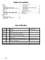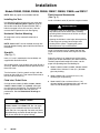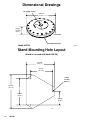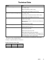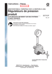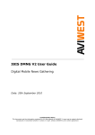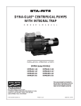
1
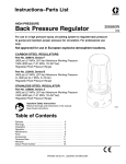
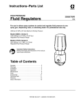
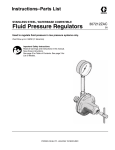
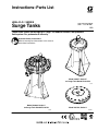
Instructions–Parts List
HIGH–FLO SERIES
307707ZAP
Surge Tanks
ENG
These tanks reduce fluid surging in a high– or medium–volume, low–pressure
fluid system. For professional use only.
Important Safety Instructions
Read all warnings and instructions in this manual.
Save these instructions.
Model 220157, Series E
on Surge Tank Stand Kit 218742
7139A
Model 238983, Series C
on Surge Tank Stand Kit 218742
7287B
Model 233736, Series A
TI1898B
Table of Contents
Warnings . . . . . . . . . . . . . . . . . . . . . . . . . . . . . . . . . . . . . . 3
Installation
All Models . . . . . . . . . . . . . . . . . . . . . . . . . . . . . . . . . . 5
Models 238983, 238984, 238985,
238986, 238987, 238988, 218509, and 220157 . . 6
Model 233736 . . . . . . . . . . . . . . . . . . . . . . . . . . . . . . . 8
Operation
All Models . . . . . . . . . . . . . . . . . . . . . . . . . . . . . . . . . . 9
Models 238983, 238984, 238985, 218509,
238985, 238986, 238987, 238988, and 220157 . 10
Model 233736 . . . . . . . . . . . . . . . . . . . . . . . . . . . . . . 12
Troubleshooting . . . . . . . . . . . . . . . . . . . . . . . . . . . . . . . 13
Service
Models 218509, 220157 . . . . . . . . . . . . . . . . . . . . . 14
Models 238983, 238984, 238985 . . . . . . . . . . . . . 15
Model 233736 . . . . . . . . . . . . . . . . . . . . . . . . . . . . . . 16
Parts Drawings and Lists
Model 218509 . . . . . . . . . . . . . . . . . . . . . . . . . . . . . .
Model 220157 . . . . . . . . . . . . . . . . . . . . . . . . . . . . . .
Models 238983, 238984, 238985, 238986,
238987, 238988 . . . . . . . . . . . . . . . . . . . . . . . . . . . .
Model 233736 . . . . . . . . . . . . . . . . . . . . . . . . . . . . . .
Dimensional Drawings . . . . . . . . . . . . . . . . . . . . . . . . .
Stand Mounting Hole Layout . . . . . . . . . . . . . . . . . . . .
Technical Data . . . . . . . . . . . . . . . . . . . . . . . . . . . . . . . .
Warranty . . . . . . . . . . . . . . . . . . . . . . . . . . . . . . . . . . . . .
Graco Information . . . . . . . . . . . . . . . . . . . . . . . . . . . . .
List of Models
Maximum Fluid
Working Pressure
Part No.
Series
Description
238983,
238986
C
High volume, electropolished stainless steel, 2 npt(f) inlet
and outlet
238984,
238987
C
High volume, electropolished stainless steel, 2 in. sanitary 300 psi (2.1 MPa, 21 bar)
inlet and outlet (Tri–Clamp compatible)
238985,
238988
C
High volume, electropolished stainless steel, 1.5 in. sanitary inlet and outlet (Tri–Clamp compatible)
300 psi (2.1 MPa, 21 bar)
233736
A
High volume, stainless steel, 1/4 bspp(f) air port, 3/4
bspp(f) fluid port
360 psi (2.5 MPa, 25 bar)
218509
E
High volume, carbon steel, 2 npt(f) inlet and outlet
600 psi (4.2 MPa, 42 bar)
220157
E
Medium volume, electropolished stainless steel, 1.25
npt(f) inlet, 1.25 npt(f) outlet
600 psi (4.2 MPa, 42 bar)
A
Surge Tank Stand Kit (not used with Part No. 233736)
n/a
300 psi (2.1 MPa, 21 bar)
Accessory
218742
2
307707
17
18
19
20
21
22
23
24
24
Symbols
Warning Symbol
Caution Symbol
WARNING
CAUTION
This symbol alerts you to the possibility of serious
injury or death if you do not follow the instructions.
This symbol alerts you to the possibility of damage to
or destruction of equipment if you do not follow the
instructions.
WARNING
EQUIPMENT MISUSE HAZARD
Equipment misuse can cause the equipment to rupture or malfunction and result in serious injury.
INSTRUCTIONS
This equipment is for professional use only.
Read all instruction manuals, tags, and labels before operating the equipment.
Use the equipment only for its intended purpose. If you are not sure, call your Graco distributor.
Do not alter or modify this equipment. Use only genuine Graco parts and accessories.
Check equipment daily. Repair or replace worn or damaged parts immediately.
Do not exceed the maximum working pressure of the lowest rated component in your system. See
Technical Data on page 23.
Use fluids and solvents that are compatible with the equipment wetted parts. Refer to the
Technical Data section of all equipment manuals. Read the fluid and solvent manufacturer’s
warnings.
Route hoses away from traffic areas, sharp edges, moving parts, and hot surfaces. Do not expose
Graco hoses to temperatures above 82C (180F) or below –40C (–40F).
Wear hearing protection when operating this equipment.
Do not lift pressurized equipment.
Comply with all applicable local, state, and national fire, electrical, and safety regulations.
PRESSURIZED EQUIPMENT HAZARD
Spray from the gun, hose leaks or ruptured components can splash fluid in the eyes or on the skin and
cause serious injury.
Do not stop or deflect fluid leaks with your hand, body, glove or rag.
Follow the Pressure Relief Procedure on page 9 when: you are instructed to relieve pressure;
stop spraying; clean, check or service the equipment; and install or clean fluid nozzles.
Do not point the spray gun at anyone or at any part of the body.
Tighten all fluid connections before operating the equipment.
Check the hoses, tubes and couplings daily. Replace worn, damaged or loose parts immediately.
Permanently coupled hoses cannot be repaired; replace the entire hose.
307707
3
WARNING
FIRE AND EXPLOSION HAZARD
Improper grounding, poor ventilation, open flames or sparks can cause a hazardous condition and
result in a fire or explosion and serious injury.
Ground the equipment. See Grounding on page 5.
If there is any static sparking or you feel an electric shock while using this equipment, stop pumping immediately. Do not use the equipment until you identify and correct the problem.
Provide fresh air ventilation to avoid the buildup of flammable fumes from solvents or the fluid
being pumped.
Keep the work area free of debris, including solvent, rags, and gasoline.
Electrically disconnect all equipment in the work area.
Extinguish all open flames or pilot lights in the work area.
Do not smoke in the work area.
Do not turn on or off any light switch in the work area while operating or if fumes are present.
Do not operate a gasoline engine in the work area.
Never use 1.1.1–trichloroethane, methylene chloride, other halogenated hydrocarbon solvents or
fluids containing such solvents in pressurized aluminum equipment. Such use could result in a
chemical reaction, with the possibility of explosion.
TOXIC FLUID HAZARD
Hazardous fluid or toxic fumes can cause serious injury or death if splashed in the eyes or on the skin,
inhaled, or swallowed.
Know the specific hazards of the fluid you are using.
Store hazardous fluid in an approved container. Dispose of hazardous fluid according to all local,
state and national guidelines.
Always wear protective eyewear, gloves, clothing and respirator as recommended by the fluid and
solvent manufacturer.
Graco does not manufacture or supply the reactive chemical components that may be used in this
equipment and is not responsible for injury or property loss, damage, expense or claims (direct or
consequential) that arise from the use of such chemical components.
MOVING PARTS HAZARD
Moving parts, such as the air motor piston in the pump, can pinch or amputate your fingers.
Keep clear of all moving parts when starting or operating the pump.
Before servicing this surge tank, follow the Pressure Relief Procedure on page 9 to prevent the
equipment from starting accidentally.
4
307707
Installation
All Models
Grounding
Ground the tank and the rest of your system. See Fire
and Explosion Hazard on page 4.
Static electricity is generated by the flow of fluid
through the pump and hose, but it is dissipated
through proper grounding. If every part of the spray
system is not properly grounded, sparking may occur,
and the system may become hazardous. Sparking
may also occur when plugging in or unplugging a
power supply cord. Sparks can ignite fumes from
solvents and the fluid being sprayed, dust particles and
other flammable substances, and can cause a fire or
explosion and serious injury and property damage.
If you experience any static sparking or feel even a
slight shock while using this equipment, stop spraying
immediately. Check for proper grounding of the entire
system. Be sure you have corrected the problem
before starting to spray again.
Ground the pump and all other spray equipment used
or located in the spray area. The following are
minimum requirements for grounding a basic spray
system. Your system may include other equipment or
objects which must also be grounded. Always check
your local electrical code for detailed grounding
instructions. Be sure your system is connected to a
true earth ground.
Pump: Ground by using a ground wire and clamp
as described in your separate pump instruction
manual.
Air compressors and hydraulic power supplies:
Follow the manufacturer’s recommendations.
All air and fluid lines: Use only grounded hoses with
a maximum of 150 m (500 ft) combined hose length
to ensure grounding continuity. See Hose
Grounding Continuity on page 5.
Surge tank: Connect a ground wire and clamp as
shown in Fig. 1. Loosen the grounding screw (W).
Insert one end of a 1.5 mm2 (12 ga.) minimum
ground wire (Y) behind the grounding screw and
tighten the screw securely. Connect the clamp end
of the ground wire to a true earth ground. Order
Part No. 222011 Ground Wire and Clamp.
Spray gun: Obtain grounding through connection to
a properly grounded fluid hose and pump.
Object being sprayed: Ground according to local
code.
Fluid supply container: Ground according to local
code.
All solvent pails used when flushing must be
grounded according to local code. Use only
grounded metal pails, which are conductive. Do not
place the pail on any non-conductive surface, such
as cardboard or paper, which would interrupt
grounding continuity.
To maintain grounding continuity when flushing or
relieving pressure, always hold a metal part of the
gun firmly to the side of a grounded metal pail, then
trigger the gun.
W
Y
Fig. 1
Hose Grounding Continuity
Proper hose grounding continuity is essential to
maintaining a grounded spray system. Check the
electrical resistance of your air and fluid hoses at least
once a week. If your hose does not have a tag on it
which specifies the maximum electrical resistance,
contact the hose supplier or manufacturer for the
maximum resistance limits. Use a resistance meter in
the appropriate range for your hose to check the
resistance. If the resistance exceeds the
recommended limits, replace the hose immediately. An
ungrounded or poorly grounded hose can make your
system hazardous.
Flushing Safety
Before flushing, be sure the entire system and flushing
pails are properly grounded, and be sure that pressure
is relieved. See Grounding and Pressure Relief
Procedure on page 9.
307707
5
Installation
Models 238983, 238984, 238985, 238986, 238987, 238988, 218509, and 220157
NOTE: Refer to page 8 to install Model 233736.
Installing the Tank
Use Stand Kit 218742 to mount the tank to the floor.
See the Stand Mounting Hole Layout on page 22.
Secure the stand (B) to the floor with M19 (5/8 in.)
bolts that engage at least 152 mm (6 in.) into the
concrete floor to prevent the tank from tipping.
Horizontal / Vertical Mounting
All surge tanks can by mounted horizontally or
vertically.
NOTE: Model 220157 can be mounted vertically with
the fluid direction flowing upward (with the fluid inlet at
the bottom).
Items J, K, and L (mentioned in the text below) are
supplied with Stand Kit 218742.
Secure the bracket (J) to the leg of the stand (B) with a
screw (K). Notice the different bracket positions for the
three tank sizes.
Turn the bracket (J) with a wrench to align it with the
bosses on the surge tank. Then secure the bracket to
the tank with the screws (L).
Fluid Inlet / Outlet Ports
On high-volume models (218509, 238983, 238984,
238985, 238986, 238987, and 238988), either port
may be used as the fluid inlet. The direction of fluid
flow through these models does not affect the
performance. See the Dimensional Drawings on
page 21.
CAUTION
The inlet and outlet adapter fittings on Models
238983, 238984, and 238985 (Ref. No. 3 on page
20) use a non-standard thread to fit into the fluid
cover (Ref. No. 1 on page 20). You must use Gracoapproved fittings to prevent thread damage. Contact
your Graco distributor for optional fittings.
307707
Install a fluid drain valve (H) near the surge tank outlet.
WARNING
A fluid drain valve (H) is required in your system to
help reduce the risk of serious injury, including
splashing fluid in the eyes or on the skin and injury
from moving parts.
Opening the fluid drain valve helps relieve pressure
in the surge tank, pumps, hose and gun after
shutting off the system. Triggering the gun to
relieve pressure may not be sufficient.
Install a fluid shutoff valve (C) before and after the
surge tank to isolate it when servicing the tank. See
Fig. 3.
Stand Kit
(See Fig. 2.)
6
Fluid Lines and Accessories
(See Fig. 3.)
Proper line sizing is an important part of the system.
Contact your Graco distributor if you need assistance.
To obtain proper flow through the system, use the
proper size plumbing from the following list:
Models 238983, 238984, 238985, 238986, 238987,
238988: Use a minimum 51 mm (2 in.) diameter
pipe and plumbing.
Model 218509: Use a minimum 51 mm (2 in.)
diameter pipe and plumbing.
Model 220157: Use a minimum 25 mm (1 in.)
diameter flexible hose between the pump and tank
and a hard or flexible pipe after the tank.
Installation
Models 238983, 238984, 238985, 238986, 238987, 238988, 218509, and 220157
Stand Kit
K
L
L
K
J
J
B
Models 218509,
238983, 238984,
238985, 238986,
238987, 238988
Model 220157
Fig. 2
B
7140B
J*
Typical Installation
J*
KEY
A
B
C
D
E
F
G
H
J
Surge tank
Stand
Fluid shutoff valve
Fluid line
Mix tank
High-Flo pump
Ground wire*
Fluid drain valve*
Bleed-type master air valve*
F
G*
E
* Required for safe operation.
Must be purchase separately.
D
G*
NOTE: This installation is only a
guide for selecting and installing a
system; it is not an actual system
design. Contact your Graco
distributor for assistance in
designing a system to suit your
needs.
A
H*
C
H*
C
B
7141B
Fig. 3
307707
7
Installation
Model 233736
Model 233736 surge tank (A) must be installed
horizontally (see Fig. 4).
Install the surge tank on a short riser tube (B) off the
fluid supply line (D). The air inlet must face up.
Install an air pressure regulator (M) and a ball valve
(N) on the air supply line (P) to the surge tank. The air
regulator controls the air pressure in the tank. The ball
valve prevents air from escaping from the tank during
operation.
Install a fluid valve (T) on the riser tube (B). Close this
valve to allow maintenance of the surge tank while fluid
continues to flow in the main fluid supply line.
Remove the plug (12) and install a fluid priming valve
(R) and drain line (S), for use in bleeding air from the
fluid section.
J*
Typical Installation
KEY
A
B
C
D
E
F
G
H
J
M
N
P
R
S
T
U
Surge tank
Riser tube
Fluid shutoff valve
Fluid line
Mix tank
High-Flo pump
Ground wire*
Fluid drain valve*
Bleed-type master air valve*
Air regulator
Air shutoff valve
Air line to surge tank
Priming valve
Fluid drain line
Fluid valve
Pump air regulator
* Required for safe operation.
Must be purchased separately.
NOTE: This installation is only a
guide for selecting and installing a
system; it is not an actual system
design. Contact your Graco
distributor for assistance in
designing a system to suit your
needs.
U
J*
F
P
G*
E
D
M
T
B
H*
C
G*
N
A
R
S
C
TI1913B
Fig. 4
8
307707
Operation
All Models
Pressure Relief Procedure
WARNING
To reduce the risk of an injury from splashing fluid
or moving parts, follow the Pressure Relief Procedure whenever you
Are instructed to relieve the pressure
Stop dispensing
Check or service any of the system equipment
Install or clean any system components
1. Turn off the power to the pump.
2. In a hydraulic system, close the hydraulic shutoff
valves.
3. In an air-powered system, close the pump air
regulator, and close the bleed-type master air
valve (required in your system).
4. Close the fluid shutoff valves from the supply
tanks.
5. Hold a metal part of the gun firmly to the side of a
grounded metal pail and trigger the gun to relieve
fluid pressure.
6. Open the fluid drain valve (required in your
system), having a container ready to catch the
drainage. Keep hands away from the end of the
drain valve when opening it.
7. Leave the drain valve open until you are ready to
use the system again.
8. For Models 238983, 238984, 238985, 238986,
238987, 238988, 218509, and 220157: To relieve
the gas charge pressure in the surge tank, remove
the cap on the charge valve (6), and press down
on the valve stem until all pressure is relieved.
NOTE: Relieving all gas pressure takes several
minutes.
For Model 233736: Back out the plug (11) to
relieve air pressure in the surge tank.
307707
9
Operation
Models 238983, 238984, 238985, 238986, 238987, 238988, 218509, and 220157
WARNING
Always follow the Pressure Relief Procedure
on page 9 before you remove the surge tank
for any reason.
Tighten all fluid connections securely before
each use.
Never try to stop or deflect leaks with your hand
or body.
Be sure the drain valve connected to the surge
tank is closed before you start the system.
Always keep hands away from the end of the
drain valve when opening it.
NOTE: Always re-torque all of the M12 cap screws
and hex nuts using a star-pattern sequence before you
charge or operate the surge tank to ensure against
fluid or gas leakage. For torque specifications for your
Model No., see the Parts Drawings on pages 17, 18,
and 19.
Charging the Tank
1. The fluid line pressure must be at zero before you
charge the tank. Pressure in the fluid line prevents
the tank from accepting a full charge.
2. Remove the relief valve cap and the tank charge
valve cap from the tank charge valve. See Fig. 5.
WARNING
To reduce the risk of fire or explosion, which could
result in serious injury and property damage,
always use an inert gas, such as nitrogen or
compressed air, to charge the tank. Never use
pure oxygen.
NOTE: Do not install a continuously fed gas charge
supply to the surge tank. Doing so will adversely affect
the surge tank performance.
3. Up to a charging pressure of 120 psi (0.84 MPa,
8.4 bar) compressed air or bottled nitrogen may be
used. For higher pressures, use only nitrogen. For
optimum performance, charge the tank to 2/3
of the anticipated fluid line operating pressure
(see table below). This pressure allows the tank
diaphragm to store enough energy for efficient
operation. Charging takes several minutes.
FLUID LINE PRESSURE
TANK CHARGE PRESSURE
600 psi (4.2 MPa, 41 bar)
400 psi (2.8 MPa, 28 bar)
500 psi (3.5 MPa, 35 bar)
334 psi (2.2 MPa, 22 bar)
400 psi (2.8 MPa, 28 bar)
268 psi (1.8 MPa, 18 bar)
300 psi (2.1 MPa, 21 bar)
200 psi (1.4 MPa, 14 bar)
200 psi (1.4 MPa, 14 bar)
134 psi (0.9 MPa, 9 bar)
100 psi (0.7 MPa, 7 bar)
67 psi (0.5 MPa, 5 bar)
CAUTION
The maximum working pressure for surge tank
Models 238983, 238984, and 238985 is 300 psi (2.1
MPa, 21 bar). For these Models, do not exceed this
fluid line pressure or the associated charge pressure
as shown in the table above.
4. Replace the two caps hand-tight.
Relieving Gas Pressure in the Tank
This tank has a pressure relief valve that
automatically relieves gas pressure (only) in the
tank if it overpressurizes while charging.
To manually relieve gas pressure in the tank,
remove the cap from the charge valve (6). Press
down the stem of the valve until all gas pressure is
relieved.
NOTE: Relieving all gas pressure takes several
minutes.
Flushing Procedure
For the best flushing results, alternate the gas charge
pressure between 2/3 of the fluid pressure (normal
operating condition) and zero pressure. This allows the
flushing solvent to reach all areas of the fluid
containing vessel.
10
307707
Operation
Models 238983, 238984, 238985, 238986, 238987, 238988, 218509, and 220157
relief valve cap
Model 218509 shown
tank charge valve cap
tank charge valve
7142B
Fig. 5
307707
11
Operation
Model 233736
WARNING
Always follow the Pressure Relief Procedure
on page 9 before you remove the surge tank
for any reason.
Relieving Air Pressure in the Tank
To manually relieve air pressure in the tank, back out
the plug (11).
Fill the Tank with Fluid
Tighten all fluid connections securely before
each use.
1. Charge the surge tank with air, as described at left.
Never try to stop or deflect leaks with your hand
or body.
2. Open the fluid valve (T). Ensure that the priming
valve (R) is open.
NOTE: Always re-torque all of the cap screws using a
star-pattern sequence before you charge or operate
the surge tank to ensure against fluid or air leakage.
For torque specifications, see the Parts Drawing on
page 20.
Charging the Tank with Air
The fluid line pressure must be at zero before you
charge the tank. Pressure in the fluid line prevents the
tank from accepting a full charge.
1. See Fig. 4 on page 8. Close the fluid valve (T).
Open the priming valve (R).
2. Open the air valve (N) and set the air regulator (M)
to the desired pressure. When the tank is charged
with air, close the air valve (N) to prevent air from
escaping when fluid is introduced.
For the best results, set the air pressure to 15 psi
(0.1 MPa, 1 bar) below the fluid pressure. Do not
exceed the maximum air pressure of 218 psi (1.5
MPa, 15 bar). For fluid pressures of 232 psi (1.6
MPa, 16 bar) and above, set the air pressure to
218 psi (1.5 MPa, 15 bar).
WARNING
To reduce the risk of fire or explosion, which could
result in serious injury and property damage,
always use compressed air to charge the tank.
Never use pure oxygen.
12
307707
3. Start the pump and slowly increase the fluid
pressure. When fluid flows from the priming valve,
close the valve. The surge tank is ready for use.
CAUTION
The maximum working pressure for Model 233736 is
360 psi (2.5 MPa, 25 bar). Do not exceed this fluid
line pressure.
Flush Before First Use
The surge tank is tested with oil in production. Oil
residue remains in the tank to protect it from corrosion.
Before using, flush the tank thoroughly with a
compatible solvent.
Troubleshooting
WARNING
CAUTION
To reduce the risk of serious injury, including
splashing fluid in the eyes or on the skin, always
follow the Pressure Relief Procedure on page 9
before you check or service the surge tank or
remove the surge tank from the system.
Problem
If you replace the diaphragm, do not attempt to make
a new one yourself. Use only genuine Graco parts.
Other materials may not stand up to the pressures
developed in the tank or to the fluid being pumped. A
ruptured diaphragm will release gas into the paint
line.
Cause
Solution
Surge tank will not accept a
gas charge.
Plugged restrictor in charge valve
(not applicable for Model 233736)
The restrictor is a safety device that
prevents overpressurization during
charging of the tank. Clean or replace
the restrictor bushing:
Ref. No. 25 on page 17.
Ref. No. 25 on page 18.
Ref. No. 13 on page 20.
Poor pulsation reduction.
Incorrect gas charge pressure
Charge the surge tank to recommended air pressure (see Operation
section).
Surge tank undersized for application
Reduce working fluid pressure and/or
flow rate.
Install a larger surge tank model.
Install a surge regulator (SR200)
Surge tank gas charge bleeds
off
off.
Extended pump change-over time
due to worn or held open check
valves
Repair the piston pump.
Ruptured diaphragm
Replace diaphragm.
Relaxed diaphragm seal
Check flange bolt torques. Re-torque
as necessary. See Parts Drawings
for torque specifications.
Damaged diaphragm seal
Replace.
Leaking charge valve or relief valve
Replace charge valve or relief valve.
307707
13
Service
(Models 218509 and 220157)
Installing Diaphragm and Seal Repair Kit
Diaphragm and Seal Repair Kits are available and can
be ordered separately as follows:
Kit 218799, for Model 218509 surge tank
Kit 234118, for Model 220157 surge tank
WARNING
Follow the Pressure Relief Procedure on page 9
before you check or service the surge tank or
remove the surge tank from the system. All fluid
and gas charge pressure must be relieved completely before you attempt any service.
See the Parts Drawings on pages 17 and 18.
Disassembly
1. To manually relieve gas pressure in the tank,
remove the relief valve cap (27) and the cap from
the charge valve (6). Press down the valve stem
until all gas pressure is relieved.
NOTE: Relieving all gas pressure takes several
minutes.
2. Disassemble the surge tank by removing the M12
cap screws (2), lock washers (3), and hex nuts (4).
NOTE: Model 220157 does not contain
lockwashers (3) or hex nuts (4).
3. Separate the air section (7) from the fluid section
(8). Be careful that you do not damage the
machined flange surfaces or components attached
to either housing.
4. Remove and discard the diaphragm (1a) and the
two o-rings (1b).
Reassembly
1. Carefully and thoroughly clean all housing flange
and o-ring sealing surfaces. Clean and dry an area
at least 12 mm (0.5 in.) inside the o-ring diameter
on the upper air housing (7) for application of the
special gasket joint sealant (38).
2. Install the new o-rings (1b), and lay the diaphragm
(1a) in place on the lower fluid housing (8).
3. Remove the printed release paper from the gasket
joint sealant (38) adhesive strip.
NOTE: Be careful not to remove the adhesive with
the release paper. Check to be sure that the
adhesive stays on the joint sealant. If the adhesive
sticks to the release paper and begins to lift off the
joint sealant, stop and trim to a new length, or start
from the opposite end and try again.
4. Place the gasket joint sealant (38) on the upper air
housing (7) within 3 mm (1/8 in.) of the internal
diameter of the o-ring groove as follows. Be careful
that you do not twist or damage the joint sealant
during installation.
a. Begin and finish the sealant ends directly
inward from a bolt hole. See Detail in Parts
Drawings.
b. Overlap the ends of the sealant by at least
10 mm (3/8 in.) as shown. Point the ends
inward.
c.
Trim off excess length of joint sealant as
necessary.
5. Reassemble the housings carefully, making sure
the joint sealant remains in place.
6. Torque the M12 cap screws (2) using a star
pattern sequence, in three successive steps, to a
final torque of 63 to 73 N-m (46 to 54 ft-lb).
7. Follow the instructions for Charging the Tank on
page 10, and see Operation on page 9 to return
the surge tank to service.
14
307707
Service
(Models 238983, 238984, 238985, 238986, 238987, 238988)
Installing Diaphragm Repair Kit
Diaphragm and Seal Repair Kit 248079 is available
and can be ordered separately.
WARNING
Follow the Pressure Relief Procedure on page 9
before you check or service the surge tank or
remove the surge tank from the system. All fluid
and gas charge pressure must be relieved completely before you attempt any service.
See the Parts Drawing on page 19.
Reassembly
1. Carefully and thoroughly clean all housing flange
and diaphragm bead sealing surfaces.
2. Lay the diaphragm (7a,b) in place on the lower
fluid housing (1) with the center contour (the
convex side) facing upward.
3. Lay the cream-colored TPE backing diaphragm (6)
over the diaphragm (7a, b). The diaphragms
should fit closely together.
4. Reassemble the air housing (2) and the fluid
housing (1) carefully. Make sure the diaphragms
remain in the grooves and are not pinched.
Disassembly
1. To manually relieve gas pressure in the tank,
remove the relief valve cap (17) and the cap from
the charge valve (15). Press down the valve stem
until all gas pressure is relieved.
NOTE: Relieving all gas pressure takes several
minutes.
2. Disassemble the surge tank by removing the M12
cap screws (8), plain washers (11), lock washers
(10), and hex nuts (9).
5. Replace the flange hardware with the capscrews,
nuts, and washers that are provided with the
Diaphragm Repair Kit.
6. Torque the M12 cap screws (8) using a
star-pattern sequence in two successive steps to a
final torque of 68 to 81 N-m (50 to 60 ft-lb).
7. Follow the Charging the Tank instructions on
page 10. See the rest of the Operation section on
page 10 to return the surge tank to service.
3. Separate the air housing (2) from the fluid housing
(1). Be careful that you do not damage the
machined flange surfaces or components attached
to either housing.
4. Remove and discard the diaphragms (6 and 7).
307707
15
Service
(Model 233736)
Diaphragm Repair
WARNING
Follow the Pressure Relief Procedure on page 9
before you check or service the surge tank or
remove the surge tank from the system. All fluid
and gas charge pressure must be relieved completely before you attempt any service.
See the Parts Drawing on page 20.
Disassembly
1. To manually relieve air pressure in the tank, back
out the plug (11).
2. Disassemble the surge tank by removing the cap
screws (8).
3. Separate the air housing (2) from the fluid housing
(1). Be careful that you do not damage the
machined flange surfaces or components attached
to either housing.
4. Remove the screw (10) and diaphragm plates (5,
6). Discard the diaphragm (7).
16
307707
Reassembly
1. Carefully and thoroughly clean all housing flange
and diaphragm sealing surfaces.
2. Apply thread sealant to the screw (10). Assemble
the air side plate (6), diaphragm (7), fluid side plate
(5), and screw (10) as shown in the parts drawing.
Torque the screw to 2 to 3 N-m (1.5 to 2.2 ft-lb).
Lay the diaphragm (7) in the lower fluid housing (1)
with the smaller air side plate facing upward.
3. Reassemble the air housing (2) and the fluid
housing (1) carefully. Make sure the diaphragm is
not pinched.
4. Replace the capscrews (8) loosely, then torque the
screws (8) to 18 to 22 N-m (13 to 16 ft-lb), using a
star-pattern sequence.
5. Follow the Charging the Tank with Air
instructions on page 12. See the rest of the
Operation section on page 12 to return the surge
tank to service.
Parts
Model 218509, Series E
carbon steel,
2 npt(f) inlet/outlet
6
2
27
26
28
2
25
29
31
2
1
7
Detail
38
38
see detail
7143A
1b
1b
1a
1b
8
3
1
Torque to 63 to 73 N-m (46 to 54 ft-lb).
2
Apply thread sealant and thread tape to
pipe threads before reassembling.
Ref
No.
Part
No.
1
218799
1a
1b
2
3
4
6
7
8
25
26
107596
107541
107539
104031
180667
180557
180969
108147
Description
REPAIR KIT, surge tank; includes
items 1a, 1b, and 38
. DIAPHRAGM
. O–RING
. CAPSCREW, hex hd; M12 x 50
. LOCKWASHER, spring
. NUT, hex; M12
VALVE, charge, tank
HOUSING, diaphragm
HOUSING, diaphragm
(Model 218509 only)
BUSHING, air valve
ELEMENT, filter
4
1
7138b
Qty.
1
1
2
24
24
24
1
1
1
1
1
Ref
No.
Part
No.
Description
27
28
29
31
33*
38
180942
108519
102042
116343
181068
192258
CAP, relief valve
O–RING; fluoroelastomer
PLUG, pipe
SCREW, grounding
TAG, warning (not shown)
GASKET JOINT SEALANT
Qty.
1
1
2
1
1
1
These parts are available in Diaphragm and Seal
Repair Kit 218799, which can be ordered separately.
*
Extra warning tags are available at no charge.
307707
17
Parts
Model 220157, Series E
electropolished stainless steel,
1.25 npt(f) inlet, 1.25 npt(f) outlet
27
2
6
28
31
26
25
Detail
2
1
38
7
17
7143A
1b
38
see detail
1b
1
Torque to 63 to 73 N-m (46 to 54 ft-lb).
2
Apply thread sealant and thread tape to
pipe threads before reassembling.
1a
1b
8
7137C
Ref
No.
Part
No.
1
234118
1a
1b
2
6
7
8
117638
104031
181408
181410
Description
REPAIR KIT, surge tank; includes
items 1a, 1b, 2, and 38
. DIAPHRAGM
. O–RING
. CAPSCREW, hex hd; M12 x 50
VALVE, charge, tank
HOUSING, diaphragm
HOUSING, diaphragm
Qty.
Ref
No.
Part
No.
Description
1
1
2
18
1
1
1
17
25
26
27
28
31
33*
38
107541
180969
108147
180942
108519
116343
181068
192258
WASHER, lock, spring
BUSHING, air valve
ELEMENT, filter
CAP, relief valve
O–RING; fluoroelastomer
SCREW, grounding
TAG, warning (not shown)
GASKET JOINT SEALANT
These parts are available in Diaphragm and Seal
Repair Kit 234118, which can be ordered separately.
*
18
307707
Extra warning tags are available at no charge.
Qty.
18
1
1
1
1
1
1
1
Parts
17
Models
238983, 238986 Series C
electropolished stainless steel, 2 npt(f) inlet/outlet
238984, 238987 Series C
electropolished stainless steel, 2-in. sanitary inlet/outlet
12
electropolished stainless steel, 1.5-in. sanitary inlet/outlet
Part
No.
1
15D038
2
3a
191768
191771
3b
187004
3c
188286
5
6
7a
107078
191407
118357
7b
15F232
8
9
10
11
12
13
14
15
16
17
18
19
21*
15W044
15W043
107541
109570
180952
180969
108147
104031
238876
180942
108519
116343
181068
4
15
4
14
238985, 238988 Series C
Ref
No.
18
16
Description
13
19
4
Qty.
COVER, fluid; electropolished SST
COVER, air; cast aluminum
FITTING, 2 npt(f)
Used on Models
238983, 238986
FITTING, 2-in. sanitary
Used on Models
238984, 238987
FITTING, 1.5-in. sanitary
Used on Models
238985, 238988
PACKING, o-ring
DIAPHRAGM, backing, TPE
DIAPHRAGM, PTFE; Used on
Models 238983, 238984, 238985
DIAPHRAGM, PTFE; Used on
Models 238986, 238987, 238988
SCREW, M12, cap, hex head
NUT, hex; M12
LOCKWASHER, spring; M12
WASHER, plain
RING, lift
BUSHING, air valve
ELEMENT, filter
VALVE, charge, tank
VALVE, relief
CAP, relief valve
O–RING; fluoroelastomer
SCREW, grounding
TAG, warning (not shown)
8
1
1
1
11
2
2
2
2
2
1
1
6
1
12
12
12
12
1
1
1
1
1
1
1
1
1
7a, 7b
3a
2
3b, 3c
2
These parts are available in Diaphragm Repair
5
Kit 248079, which can be ordered separately.
Extra warning tags are available at no charge.
Included in repair kit 249141.
*
5
3
5
10
1
Torque to 68 to 81 N-m (50 to 60 ft-lb).
2
Torque to 136 to 149 N-m
(100 to 110 ft-lb).
3
4
5
5
2
Apply lubricant to o-ring
surface before reassembling.
Apply thread sealant and
thread tape to pipe threads
before reassembling.
3
1
9
1
3b, 3c
7286C
2
3a
Non-standard thread. Use
Graco-approved fittings only.
307707
19
Parts
Model 233736, Series A
stainless steel, 1/4 bspp(f) air port, 3/4 bspp(f) fluid port
Ref
No.
Part
No.
1
2
5
6
7
8
9
10
11
12
19
20
198776
198775
198779
198778
198777
117033
116898
116899
116901
116902
116343
15F749
Description
Qty.
COVER, fluid;SST
COVER, air; cast aluminum
PLATE, diaphragm, fluid side
PLATE, diaphragm, air side
DIAPHRAGM, PTFE
SCREW, M10, cap, socket head
WASHER
SCREW, cap, socket head
PLUG, hex head
PLUG, socket head
SCREW, grounding
WASHER, seal
1
1
1
1
1
18
1
1
1
1
1
1
11
19
8
5
20
3
2
Keep this part on hand to reduce down time.
6
7
5
10
1
Apply thread sealant.
2
Torque to 2 to 3 N-m (1.5 to 2.2 ft-lb).
3
Torque to 18 to 22 N-m (13 to 16 ft-lb).
4
5
Torque to 47 to 55 N-m (35 to 40 ft-lb).
1
2
1
9
12
4
Torque to 43.4 N-m (32 ft-lb).
TI1899B
20
307707
Dimensional Drawings
334 mm
(13.1 in.)
268 mm
(10.6.in.)
1.25 – 11.5
npt(f) fluid inlet
2 – 11.5
npt(f) fluid
port,
inlet /
outlet
2 – 11.5
npt(f) fluid
port,
inlet /
outlet
1.25 – 11.5
npt(f) fluid
outlet
284 mm
(11.2.in.)
648 mm
(25.5 in.)
383 mm
(15.1.in.)
383 mm
(15.1 in.)
7144A
Model 220157
Model 218509
highest
point
fluid inlet / outlet:
Models 238984, 238987 2 npt(f)
Models 238984, 238987 2-in.
sanitary
(Tri-Clamp compatible)
Models 238985, 238988 1.5-in.
sanitary
(Tri-Clamp compatible)
2 npt(f) shown
7139A
409 mm
(16.1 in.)
fluid inlet / outlet:
Models 238984, 238987 2 npt(f)
Models 238984, 238987 2-in.
sanitary
(Tri-Clamp compatible)
Model 238985, 238988 1.5-in.
sanitary
(Tri-Clamp compatible)
2 npt(f) shown
465 mm
18.3 in.
(all models)
480 mm
18.9 in.
693 mm
27.3 in.
7287B
Models 238983, 238984, 238985, 238986, 238987, 238988
307707
21
Dimensional Drawings
1/4 bspp(f) air port
300 mm
(11.8 in.)
Height:
102 mm
(4.0 in.)
3/4 bspp(f) fluid port
Model 233736
TI1898B
Stand Mounting Hole Layout
(Stand is not used with Model 233736)
350 mm
(13.8 in.)
278 mm
(10.9 in.)
3 holes
17.5 mm
(0.69 in.)
397 mm
(15.6 in.)
320 mm
(12.6 in.)
160 mm
(6.3 in.)
7144A
22
307707
Technical Data
Category
Data
Maximum fluid working pressure
Models 238983, 238984, 238985, 238986, 238987, 238988: 300
psi (2.1 MPa, 21 bar)
Model 233736: 360 psi (2.5 MPa, 25 bar)
Models 218509, 220157: 600 psi (4.2 MPa, 42 bar)
Maximum gas charge pressure
Models 238983, 238984, 238985, 238986, 238987, 238988: 300
(maximum air inlet pressure for Model 233736) psi (2.1 MPa, 21 bar)
Model 233736 (air inlet pressure): 218 psi (1.5 MPa, 15 bar)
Models 218509, 220157: 600 psi (4.2 MPa, 42 bar)
Maximum flow rate*
Models 238983, 238984, 238985,238986, 238987, 238988
218509: 76 lpm (20 gpm)
Model 233736: tank volume is 1.5 liters (0.4 gal.); fluid does not
flow through tank
Model: 220157: 57 lpm (15 gpm)
Maximum operating temperature
Model 233736: 80 C (176 F)
All other models: 50 C (120 F)
Wetted parts
Models 238983, 238984, 238985, 238986, 238987, 238988: 304
& 316 stainless steel, PTFE.
Model 233736: stainless steel, PTFE
Model 218509, 220157: carbon steel, electroless
nickel-plated steel, UHMW polyethylene, fluoroelastomer, PTFE
Model 220157: 304 and 17–4 PH stainless steel, UHMW polyethylene, fluoroelastomer, PTFE, tungsten carbide
* Maximum flow rates are recommended maximums for peak performance. Exceeding these values reduces
the surge tank’s ability to dampen pulsation.
Tri-Clamp is a registered trademark of Tri-Clover Inc.
Canadian Registration Number (CRN)
Model
Alberta
Ontario
218509
0C04874.52
0C4874.5R1
220157
0C04874.52
0C4874.5R1
307707
23
Graco Standard Warranty
Graco warrants all equipment manufactured by Graco and bearing its name to be free from defects in material and workmanship on the
date of sale to the original purchaser for use. With the exception of any special, extended, or limited warranty published by Graco,
Graco will, for a period of twelve months from the date of sale, repair or replace any part of the equipment determined by Graco to be
defective. This warranty applies only when the equipment is installed, operated and maintained in accordance with Graco’s written
recommendations.
This warranty does not cover, and Graco shall not be liable for general wear and tear, or any malfunction, damage or wear caused by
faulty installation, misapplication, abrasion, corrosion, inadequate or improper maintenance, negligence, accident, tampering, or
substitution of non–Graco component parts. Nor shall Graco be liable for malfunction, damage or wear caused by the incompatibility of
Graco equipment with structures, accessories, equipment or materials not supplied by Graco, or the improper design, manufacture,
installation, operation or maintenance of structures, accessories, equipment or materials not supplied by Graco.
This warranty is conditioned upon the prepaid return of the equipment claimed to be defective to an authorized Graco distributor for
verification of the claimed defect. If the claimed defect is verified, Graco will repair or replace free of charge any defective parts. The
equipment will be returned to the original purchaser transportation prepaid. If inspection of the equipment does not disclose any defect
in material or workmanship, repairs will be made at a reasonable charge, which charges may include the costs of parts, labor, and
transportation.
THIS WARRANTY IS EXCLUSIVE, AND IS IN LIEU OF ANY OTHER WARRANTIES, EXPRESS OR IMPLIED, INCLUDING BUT
NOT LIMITED TO WARRANTY OF MERCHANTABILITY OR WARRANTY OF FITNESS FOR A PARTICULAR PURPOSE.
Graco’s sole obligation and buyer’s sole remedy for any breach of warranty shall be as set forth above. The buyer agrees that no other
remedy (including, but not limited to, incidental or consequential damages for lost profits, lost sales, injury to person or property, or any
other incidental or consequential loss) shall be available. Any action for breach of warranty must be brought within two (2) years of the
date of sale.
Graco makes no warranty, and disclaims all implied warranties of merchantability and fitness for a particular purpose in connection
with accessories, equipment, materials or components sold but not manufactured by Graco. These items sold, but not manufactured
by Graco (such as electric motors, switches, hose, etc.), are subject to the warranty, if any, of their manufacturer. Graco will provide
purchaser with reasonable assistance in making any claim for breach of these warranties.
In no event will Graco be liable for indirect, incidental, special or consequential damages resulting from Graco supplying equipment
hereunder, or the furnishing, performance, or use of any products or other goods sold hereto, whether due to a breach of contract,
breach of warranty, the negligence of Graco, or otherwise.
FOR GRACO CANADA CUSTOMERS
The parties acknowledge that they have required that the present document, as well as all documents, notices and legal proceedings
entered into, given or instituted pursuant hereto or relating directly or indirectly hereto, be drawn up in English. Les parties
reconnaissent avoir convenu que la rédaction du présente document sera en Anglais, ainsi que tous documents, avis et procédures
judiciaires exécutés, donnés ou intentés à la suite de ou en rapport, directement ou indirectement, avec les procedures concernées.
Graco Information
For the latest information about Graco products, visit www.graco.com.
TO PLACE AN ORDER, contact your Graco distributor or call to identify the distributor closest to you:
Phone: 612–623–6921 or Toll Free: 1–800–328–0211 Fax: 612–378–3505
All written and visual data contained in this document reflect the latest product information available at the time of publication.
Graco reserves the right to make changes at any time without notice.
Original instructions. This manual contains English. MM 307707
Graco Headquarters: Minneapolis
International Offices: Belgium, China, Japan, Korea
GRACO INC. AND SUBSIDIARIES S P.O. BOX 1441 S MINNEAPOLIS MN 55440–1441 S USA
Copyright 1984, Graco Inc. All Graco manufacturing locations are registered to ISO 9001.
www.graco.com
Revised 07/2011
24
307707