1
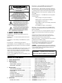
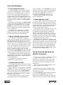
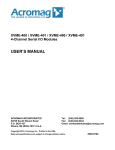
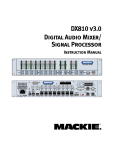
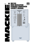
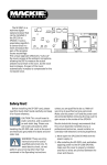
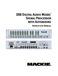
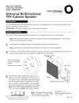
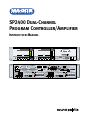
SP2400 Dual-Channel
Program Controller/Amplifier
Instruction Manual
MASTER
VOLUME
ZONE A
MASTER
VOLUME
ZONE B
3
0
3
6
9
15
30
55
INPUTS
3
0
3
6
9
15
30
55
INPUTS
SP2400 MUSIC CONTROLLER
A
B
OVERLOAD
1
2
3
4
1
2
3
4
OFF
115V 60Hz FUSE 115/T8A 220 WATTS
230V 50Hz FUSE 230/T4A 220 WATTS
DIRECT
PAGING MIC
PROGRAM INPUTS
L
THE FOLLOWING ARE TRADEMARKS OR REGISTERED TRADEMARKS OF MACKIE DESIGNS INC
"MACKIE.","MACKIE INDUSTRIAL", AND THE "RUNNING MAN" FIGURE. COPYRIGHT ©2000 ALL RIGHTS RESERVED
LOCAL
1
2
3
4
POWER
COMM PORT
MANUFACTURING DATE
SERIAL NUMBER
SP2400
MUSIC CONTROLLER
ON
STATUS
OFF
STEREO
GROUND
ALL CALL
ZONE A
ZONE B
PARALLEL
INPUTS
PHANTOM
G
+
–
GAIN +40dB
GAIN
CONTROL
LOW
HIGH
U
U
–12 +12
–12 +12
R
1 2 3 4 5 6 7 8
EXPANSION IN
CAUTION:
TO REDUCE THE RISK OF FIRE
REPLACE WITH SAME TYPE FUSE AND RATING
MIC/LINE INPUT B
PHANTOM
G
B
1
2
3
G
+
–
RS485
4
2
1 2 3 4
4
ON
3
-
+
MONO
GAIN
LOW
HIGH
U
U
REMOTE
AMBIENT
MIC
-
+
–12 +12 –12 +12
LOW 80Hz
MID
FREQ
HIGH 12k
U
U
1K
U
PRE OUT
G
+
MIC/LINE INPUT A
ZONE A
–
400
PHANTOM
OUTPUT SUITABLE
FOR CLASS 2 WIRING
+ –
100/ 70V/8
A
3K
G
B
1
2
3
G
+
–
GAIN
I
–15 +15
-
+
AMP IN
–15 +15
250
8k
–15 +15
HIGH
U
U
GAIN +40dB
RS485
REMOTE
AMBIENT
MIC
-
+
–12 +12 –12 +12
MIC
VOX
LOW 80Hz
MID
U
U
FREQ
HIGH 12k
1K
U
PRE OUT
G
1 2 3 4
0 1 2 3 4 5 6 7 8
AMP ADDRESS
LOW
PROGRAM EQ
PAGING
STEREO LEFT
MIC
VOX
GAIN +40dB
1 2 3 4
0 1 2 3 4 5 6 7 8
AMP ADDRESS
3
PROGRAM EQ
PAGING
STEREO RIGHT
OUTPUT SUITABLE
FOR CLASS 2 WIRING
+ –
100/ 70V/8
A
2
REMOTE
1
OUTPUT
PRIORITY
CONCEIVED, DESIGNED, AND MANUFACTURED BY MACKIE DESIGNS INC. • WOODINVILLE • WA • MADE IN USA • FABRIQUE AU USA
ZONE B
I
1
EXPANSION OUT
1 2 3 4
+
–
400
–15 +15
-
+
AMP IN
–15 +15
3K
250
8k
–15 +15
CAUTION
AVIS
8. Power Sources — Connect the SP2400 to a power supply only of the type
described in these operation instructions or as marked on the rear panel.
RISK OF ELECTRIC SHOCK
DO NOT OPEN
RISQUE DE CHOC ELECTRIQUE
NE PAS OUVRIR
9. Power Cord Protection — Route power supply cords so that they are not likely to be
walked upon or pinched by items placed upon or against them, paying particular attention
to cords at plugs, convenience receptacles, and the point where they exit the SP2400.
CAUTION: TO REDUCE THE RISK OF ELECTRIC SHOCK
DO NOT REMOVE COVER (OR BACK)
NO USER-SERVICEABLE PARTS INSIDE
REFER SERVICING TO QUALIFIED PERSONNEL
10. Object and Liquid Entry — Do not drop objects into or spill liquids into the inside
of the SP2400.
ATTENTION: POUR EVITER LES RISQUES DE CHOC
ELECTRIQUE, NE PAS ENLEVER LE COUVERCLE. AUCUN
ENTRETIEN DE PIECES INTERIEURES PAR L'USAGER. CONFIER
L'ENTRETIEN AU PERSONNEL QUALIFIE.
AVIS: POUR EVITER LES RISQUES D'INCENDIE OU
D'ELECTROCUTION, N'EXPOSEZ PAS CET ARTICLE
A LA PLUIE OU A L'HUMIDITE
11. Damage Requiring Service — The SP2400 should be serviced only by qualified
service personnel when:
A. The power-supply cord or the plug has been damaged; or
B. Objects have fallen, or liquid has spilled into the SP2400; or
C. The SP2400 has been exposed to rain; or
The lightning flash with arrowhead symbol within an equilateral
triangle is intended to alert the user to the presence of uninsulated
"dangerous voltage" within the product's enclosure, that may be
of sufficient magnitude to constitute a risk of electric shock to persons.
Le symbole éclair avec point de flèche à l'intérieur d'un triangle
équilatéral est utilisé pour alerter l'utilisateur de la présence à
l'intérieur du coffret de "voltage dangereux" non isolé d'ampleur
suffisante pour constituer un risque d'éléctrocution.
The exclamation point within an equilateral triangle is intended to
alert the user of the presence of important operating and maintenance
(servicing) instructions in the literature accompanying the appliance.
Le point d'exclamation à l'intérieur d'un triangle équilatéral est
employé pour alerter les utilisateurs de la présence d'instructions
importantes pour le fonctionnement et l'entretien (service) dans le
livret d'instruction accompagnant l'appareil.
1. SAFETY INSTRUCTIONS
1. Read Instructions — Read all the safety and operation instructions before
operating the SP2400.
2. Retain Instructions — The safety and operating instructions should be kept for
future reference.
3. Heed Warnings — Follow all warnings on the SP2400 and in these operating
instructions.
4. Follow Instructions — Follow all operating and other instructions.
5. Water and Moisture — Do not use the SP2400 near water – for example, near a
bathtub, washbowl, kitchen sink, laundry tub, in a wet basement, near a swimming
pool, etc.
6. Ventilation — This SP2400 should be situated so that its location or position
does not interfere with its proper ventilation. For example, it should not be
situated on a bed, sofa, rug, or similar surface that may block any ventilation
openings, or placed in a built-in installation such as a bookcase or cabinet that
may impede the flow of air through ventilation openings.
7. Heat — Locate the SP2400 away from heat sources such as radiators, or other
devices which produce heat.
D. The SP2400 does not appear to operate normally or exhibits a marked
change in performance; or
E. The SP2400 has been dropped, or its chassis damaged.
12. Servicing — The user should not attempt to service the SP2400 beyond those
means described in this operating manual. All other servicing should be referred to the
Mackie Service Department.
13. To prevent electric shock, do not use this polarized plug with an extension cord,
receptacle or other outlet unless the blades can be fully inserted to prevent blade
exposure.
Pour prévenir les chocs électriques ne pas utiliser cette fiche polariseé avec un
prolongateur, un prise de courant ou une autre sortie de courant, sauf si les lames
peuvent être insérées à fond sans laisser aucune pariie à découvert.
14. Grounding or Polarization — Precautions should be taken so that the grounding or
polarization means of the SP2400 is not defeated.
15. This apparatus does not exceed the Class A/Class B (whichever is applicable)
limits for radio noise emissions from digital apparatus as set out in the radio
interference regulations of the Canadian Department of Communications.
ATTENTION —Le présent appareil numérique n’émet pas de bruits radioélectriques
dépassant las limites applicables aux appareils numériques de class A/de class B (selon
le cas) prescrites dans le règlement sur le brouillage radioélectrique édicté par les
ministere des communications du Canada.
WARNING — To reduce the risk of fire or electric
shock, do not expose this appliance to rain or moisture.
USING INPUTS 1-4 ........................................... 18
TABLE OF CONTENTS
USING THE 3-BAND EQ ................................... 19
1.
SAFETY INSTRUCTIONS ....................................... 2
USING THE PAGING MIC ................................. 19
2.
INTRODUCTION ..................................................... 3
USING THE AMBIENT MIC .............................. 20
KEY FEATURES ................................................... 3
USING THE LOCAL MIC/LINE INPUT .............. 20
FRONT PANEL FEATURES ................................. 4
USING THE PRE OUT/AMP IN CONNECTIONS .. 21
REAR PANEL FEATURES .................................... 4
LEFT AND RIGHT OUTPUTS ............................ 21
INSTALLATION ....................................................... 6
USING THE REMOTE CONNECTION .............. 21
APPLICATION DIAGRAMS ................................. 6
USING THE RS485 CONNECTION ................... 22
TIPS ON INSTALLING AND USING
THE SP2400 ....................................................... 10
UPGRADING THE SOFTWARE ........................ 22
3.
4.
5.
SPECIFICATIONS .................................................. 23
CONNECTIONS ................................................. 11
BLOCK DIAGRAM ............................................. 23
INTERNAL SETTINGS ...................................... 13
SP2400 SPECIFICATIONS ................................. 24
AC POWER CONSIDERATIONS ....................... 15
6.
THERMAL CONSIDERATIONS ......................... 15
APPENDIX A: Default Settings ................................... 25
OPERATION .......................................................... 16
APPENDIX B: Button Modes ....................................... 26
SP2400 – 2
SP2400 QUICK START ...................................... 16
SERVICE INFORMATION ..................................... 25
APPENDIX C: Voltage Conversion ............................. 27
2. INTRODUCTION
The SP2400 is a microprocessor-based dualchannel music controller with two built-in power
amplifiers designed for use in a variety of installations
requiring high performance, flexible features, and
ease of use, such as retail stores, restaurants, bars,
and theme venues. It provides two outputs that can
be used for either stereo operation or two-zone
coverage. Four stereo line-level inputs are provided
on the rear panel, along with a paging mic input and
two local mic/line inputs.
The program input sources can be independently
assigned to each zone with the Input Select
switches on the front panel. The boxes under the
Input Select buttons on the front panel are sized to
accept Brother P-Touch® labels. Each of the four
inputs has an integral AGC circuit to automatically
compensate for level differences between the input
sources. Input 1 has a buffered line-level output that
may be used for music-on-hold or other external
applications. Program Priority can be assigned to
Input 4 for use with a jukebox or alternative paging
configurations. When a signal is detected at Input 4,
it overrides any other program source assigned to
that channel or zone.
Each of the four input sources can be operated
in either stereo or mono mode. Each zone has a 3band EQ with sweepable mid for tuning the four
program sources.
Each mic input has a 40 dB gain switch for use
with either mic or line-level signals as well as a
variable gain trim, phantom power switch, and a twoband EQ.
In addition, each zone has a variable VOX control
for adjusting the trigger threshold of the paging mic's
ducking circuit. The paging mic operates in both
zones when voice-activated, but can be assigned to
operate in either Zone A or Zone B, or over the entire
system when manually operated with a switch
connected to the PAGING MIC CONTROL connector.
Each zone is equipped with an input for an
optional ambient microphone that can sample the
ambient noise level in the room. The microprocessor
then adjusts the paging mic gain in each zone to
compensate for increased or decreased noise levels
so that the paging mic is always audible above the
background noise.
The Master Volume Up/Down buttons adjust the
overall level that is routed to the PRE OUT
connector (and the AMP IN connector when the
jumper is installed). Internal jumpers are provided
for configuring the amplifier outputs for 70V, 100V,
or 8-ohm operation.
Part No. 0000117 Rev. A 08/01
© 2001 All Rights Reserved. Mackie Industrial. Printed in U.S.A.
Audio expansion connectors are provided on the
rear panel for connecting multiple SP2400s, with
shared audio via balanced busing. Each of the four
program input signals are internally balanced and
can be independently assigned to the balanced bus
with internal assignment switches. The LOCAL/
REMOTE switches on the rear panel are provided for
selecting either local or bus operation for each
input. The paging mic and paging control signal are
also carried over the expansion bus.
A wired remote control is available that can be
used to select input sources and adjust volume levels
for each zone. Each amplifier can be programmed
with a unique address, and two amplifiers with the
same address can be controlled by a single remote
when interconnected by means of the RS485 port.
The remote control fits into a double-gang electrical
box with a Decora®-style faceplate.
In addition, the RS485 port can interface with thirdparty control systems, or a PC-compatible computer
loaded with the SPLinker software application for
computer control of up to 32 zones in a system.
An internal option slot is provided on each of the
two channels for installing an optional DSP card (SPDSP). It provides additional ambient noise sensing
for the Program Inputs using the optional ambient
microphone. As the noise level in the room increases,
the gain on the selected source gradually increases
to keep the music audible above the background noise.
An RS232 port (COMM PORT) is provided on the
front panel for connecting a Palm™ Handheld or
PC-compatible laptop computer for configuring the
optional DSP card.
KEY FEATURES
•
Two Channel Controller/Amplifier
•
4 Stereo, Line-Level Program Inputs
•
1 Page Mic Input
•
1 Local Mic Input per Channel
•
Digital Cross-Fade between Input Sources
•
200 Watts/Channel at 70V and 100V
•
200 Watts/Channel at 8 Ohms
•
Transformerless Amplifier Outputs
•
Ambient Noise Sensing for Page Mic
•
AGC for Music Sources
•
3-Band Sweepable EQ for Music Sources
•
2-Band EQ on each Mic Input
•
Dual-Zone or Stereo Operation
•
Each Zone Addressable (0-31)
•
REMOTE connection for optional Remote Control
•
RS485 Port for Third-Party Control Systems
SP2400 – 3
FRONT PANEL FEATURES
REAR PANEL FEATURES
INPUTS select buttons are used to choose the
program source for its respective zone. Only one
source may be selected at a time. These are nonpriority inputs. However, Input 4 can become a
Program Priority Input by setting the AMP
ADDRESS
switch #7 UP. In this mode, when a
signal is present on Input 4, it automatically
overrides whatever input source is selected for that
zone. This is useful for jukeboxes or alternative
paging configurations.
PROGRAM INPUTS 1-4 are stereo RCA
unbalanced inputs that accept line-level signals. The
LOCAL/REMOTE
switches on the rear panel select
either the local program input signal connected here
or the program signal on the expansion bus. See
"Expansion In/Out" on page 18 for more information.
DIRECT OUTPUT is a buffered line-level output
providing the stereo signal from the program source
connected to INPUT 1. Signal is always present at
the DIRECT OUTPUT, regardless of whether INPUT 1
is selected as the source. This is useful for musicon-hold and other external applications.
INPUT OFF deselects Inputs 1-4 and activates
the MIC/LINE INPUT .
PAGING MIC is the connection for the paging
microphone. There are two connectors available: a
3-pin XLR and a 3-pin Phoenix-type connector. In
both cases, pin 1 is ground, pin 2 is signal high (+),
and pin 3 is signal low (–).
MASTER VOLUME is used to adjust the overall
volume level for Inputs 1-4.
When OFF is selected, the Up/Down MASTER
VOLUME buttons adjust the output level for the
MIC/LINE INPUT . The Master Volume setting for
Inputs 1-4 is retained in memory, and is recalled
when a program source is selected.
CONTROL is a Phoenix-type connector for
connecting external normally-open switches for
remote paging. Three options are available: page to
Zone A, page to Zone B, and page to the entire
system (ALL CALL). Connect the switches between
GROUND and the option of choice.
The Meter indicates the level at the PRE OUT
jack. Normally, it operates as a peak program meter
(PPM). When adjusting the MASTER VOLUME
level, the meter changes from level indication to
level setting indication. After five seconds, the
meters switch back to normal peak program
metering.
PHANTOM applies phantom power (+24VDC) to
pins 2 and 3 of the microphone input. Move both
switches to the down position to turn on phantom
power.
There are three STATUS indicators. The
OVERLOAD LEDs indicate when one of the
amplifiers is beginning to current limit. The ON
LED indicates when the SP2400 is operating.
The GAIN +40 dB DIP switch is used to set the
gain for use with either a mic-level or a line-level
signal. Move both switches to the down position for
mic-level signals, and up for line-level signals.
The COMM PORT is used to connect to the
optional DSP card with a Palm™ Handheld or PCcompatible laptop computer for configuration.
The GAIN variable control is used to trim the mic
preamp gain for the best signal-to-noise ratio.
The LOW variable control is a shelving filter that
provides 12 dB of boost and cut below 100Hz.
Turning the POWER switch on activates the softstart circuit in the power supply. The soft-start
circuit impedes in-rush current from the AC supply.
The HIGH variable control is a shelving filter that
provides 12 dB of boost and cut above 12kHz.
The PAGING MIC VOX variable control adjusts
the ducking threshold for the paging mic. Rotate the
control clockwise to reduce the threshold. Rotate the
control counterclockwise to increase the threshold.
MASTER
VOLUME
ZONE A
3
0
3
6
9
15
30
55
INPUTS
MASTER
VOLUME
ZONE B
3
0
3
6
9
15
30
55
INPUTS
SP2400 MUSIC CONTROLLER
A
B
OVERLOAD
1
2
3
4
1
OFF
SP2400 – 4
2
3
4
OFF
ON
STATUS
COMM PORT
POWER
SP2400s together in a serial fashion. Any of the four
program sources from any SP2400 can be used as
the source for any of the zones in the system by
assigning it to the expansion bus with the internal
Bus Assign switches. This is a balanced bus for the
four stereo input sources. In addition, the paging
mic and paging control signal are also provided on
the EXPANSION bus.
MIC/LINE INPUT is provided to connect a local
microphone in each zone. This is a 3-pin Phoenixtype connector where pin 1 is ground, pin 2 is signal
high (+), and pin 3 is signal low (–).
AMBIENT MIC is a 3-pin Phoenix-type connector
used to connect the optional MT-3100 ambient
microphone, one for each zone. This microphone is
used to detect the ambient noise level in the room.
The microprocessor uses this information to adjust
the paging mic level above the ambient noise. The
ambient mic also provides an input for the optional
DSP card when it is installed.
LOCAL/REMOTE is a set of eight DIP switches
used to select the input source for the channel.
Each program input has two switches, one to select
the left signal source (odd-numbered switches) and
one to select the right signal source (evennumbered switches). Move the switches up to
select the local program source, and down to select
the remote (external) program source from the
EXPANSION bus.
EQ is a 3-band equalizer with a sweepable
midrange that only affects Inputs 1-4. LOW is a
shelving filter that provides 15 dB of boost and cut
below 80Hz. MID is a peaking filter that provides
15 dB of boost and cut at the selected frequency
between 250Hz and 8kHz. HIGH is a shelving filter
that provides 15 dB of boost and cut above 12kHz.
STEREO/MONO switches configure each input
source for either stereo or mono operation. If the
SP2400 is being used in a stereo configuration,
leave the switches up. If it’s being used in a zone
configuration, move the switches down to combine
the left and right channels for mono operation.
AMP ADDRESS is used to assign a unique
address to each amplifier, as well as to enable or
disable features. Switches 1-5 provide 32 separate
addresses, switch 6 determines Master/Slave
status, switch 7 enables Input 4 Priority, and switch
8 enables the optional ambient mic. Any two
amplifiers assigned to the same address can be
controlled by a single remote control when
connected together via the RS485 ports.
PRE OUT is an unbalanced RCA jack that
provides a line-level signal from the preamplifier
stage of the SP2400. This provides a method for
inserting an external signal processor into the signal
chain prior to the amplifier stage. The U-shaped
jumper wire should remain installed between the
PRE OUT and AMP IN jacks for normal operation.
RS485 is a 3-pin Phoenix-type connector in each
zone that provides an interface for the SPLinker
Sound Palette Control PC application software for
centralized computer control of up to 32 zones, as
well as communication between SP2400s.
AMP IN is an unbalanced RCA jack that accepts
a line-level signal. See PRE OUT above.
ZONE A/ZONE B OUTPUTS are 2-pin Phoenixtype connectors that provide speaker-level signals.
The SP2400 is shipped with the outputs configured
for 70-volt operation in U.S. versions, and 100-volt
operation in European versions. Internal jumpers are
provided to configure the amplifier for 8 ohm
systems as well. See page 14 for more information.
The RS485 interface is internally connected
between the two amplifiers, so if both amplifiers are
assigned the same zone with the AMP ADDRESS
switch, the front panel controls and remote controls
operate both sides, ideal for stereo operation.
REMOTE is a 3-pin Phoenix-type connector for
the optional wired remote control (SP-41R), which
provides Input Select and Master Volume control.
Connect the supplied AC linecord to the IEC AC
Socket. The AC line fuse is contained in the socket,
behind the cover located at the bottom of the
socket. Use replacement fuses only as indicated on
the rear panel.
EXPANSION IN/OUT consists of two parallel 25pin D-Sub connectors for connecting multiple
115V 60Hz FUSE 115/ T8A 220 WATTS
230V 50Hz FUSE 230/ T4A 220 WATTS
DIRECT
PAGING MIC
PROGRAM INPUTS
MANUFACTURING DATE
SERIAL NUMBER
SP2400
MUSIC CONTROLLER
L
THE FOLLOWING ARE TRADEMARKS OR REGISTERED TRADEMARKS OF MACKIE DESIGNS INC
"MACKIE.","MACKIE INDUSTRIAL", AND THE "RUNNING MAN" FIGURE. COPYRIGHT ©2000 ALL RIGHTS RESERVED
LOCAL
1
2
3
4
STEREO
GROUND
ALL CALL
ZONE A
ZONE B
PARALLEL
INPUTS
PHANTOM
G
+
–
GAIN +40dB
GAIN
CONTROL
LOW
HIGH
U
U
–12 +12
–12 +12
R
1 2 3 4 5 6 7 8
EXPANSION IN
CAUTION:
TO REDUCE THE RISK OF FIRE
REPLACE WITH SAME TYPE FUSE AND RATING
MIC/LINE INPUT B
PHANTOM
G
B
1
2
3
G
+
–
RS485
4
2
1 2 3 4
4
ON
3
-
+
MONO
GAIN
LOW
HIGH
U
U
REMOTE
AMBIENT
MIC
-
+
–12 +12 –12 +12
LOW 80Hz
MID
FREQ
HIGH 12k
U
U
1K
U
PRE OUT
G
+
MIC/LINE INPUT A
ZONE A
–
400
PHANTOM
OUTPUT SUITABLE
FOR CLASS 2 WIRING
+ –
100/70V/8
A
3K
G
B
1
2
3
G
+
–
GAIN
I
–15 +15
-
+
AMP IN
–15 +15
250
8k
–15 +15
0
LOW
HIGH
U
U
AMP ADDRESS
GAIN +40dB
RS485
REMOTE
AMBIENT
MIC
-
+
–12 +12 –12 +12
MIC
VOX
LOW 80Hz
MID
U
U
FREQ
HIGH 12k
1K
U
PRE OUT
G
1 2 3 4
1 2 3 4 5 6 7 8
PROGRAM EQ
PAGING
STEREO LEFT
MIC
VOX
GAIN +40dB
1 2 3 4
0 1 2 3 4 5 6 7 8
AMP ADDRESS
3
PROGRAM EQ
PAGING
STEREO RIGHT
OUTPUT SUITABLE
FOR CLASS 2 WIRING
+ –
100/70V/8
A
2
REMOTE
1
OUTPUT
PRIORITY
CONCEIVED, DESIGNED, AND MANUFACTURED BY MACKIE DESIGNS INC. • WOODINVILLE • WA • MADE IN USA • FABRIQUE AU USA
ZONE B
I
1
EXPANSION OUT
1 2 3 4
+
–
400
–15 +15
-
+
–15 +15
3K
250
8k
–15 +15
AMP IN
SP2400 – 5
3. Installation
Application Diagrams
Jukebox
Remote Control
Cassette or DAT Recorder
+3
0
–3
–6
–9
– 15
– 30
– 55
CD Player
Digital Satellite Service
INPUT 4 PRIORITY OFF/ON
AMBIENT MIC OFF/ON
ZONE A
Paging Mic
I
0 1 2 3 4 5 6 7 8
To Telephone System
Music-On-Hold
OFF ON
UP
MASTER/SLAVE
1 2 3 4
230/115V 50/60 Hz FUSE 115/T8A
DIRECT
PAGING MIC
PROGRAM INPUTS
MANUFACTURING DATE
SERIAL NUMBER
SP2400
MUSIC CONTROLLER
0 1 2 3 4 5 6 7 8
OFF ON
I
THE FOLLOWING ARE TRADEMARKS OR REGISTERED TRADEMARKS OF MACKIE DESIGNS INC
"MACKIE.","MACKIE INDUSTRIAL", AND THE "RUNNING MAN" FIGURE. COPYRIGHT ©2000 ALL RIGHTS RESERVED
AMP ADDRESS
2
3
EXPANSION IN
TO REDUCE THE RISK OF FIRE
REPLACE WITH SAME TYPE FUSE AND RATING
MIC/LINE INPUT B
PHANTOM
–
A
G
B
1
2
3
G
+
–
GAIN
3
4
–
B
GAIN +40dB
GAIN
CONTROL
AMP ADDRESS
RS485
2
3
4
1 2 3 4
2
1
OUTPUT
PRIORITY
1 2 3 4
4
ON
3
-
LOW
+
HIGH
U
U
–12 +12
–12 +12
MONO
HIGH
PROGRAM EQ
U
U
REMOTE
AMBIENT
MIC
-
+
LOW 80Hz
MID
FREQ
HIGH 12k
U
U
1K
U
OUTPUT
+
–12 +12 –12 +12
+
–
400
–15 +15
-
+
AMP IN
–15 +15
8k
–
A
3K
250
PHANTOM
I
–15 +15
PROGRAM EQ
PAGING
GAIN +40dB
MIC
VOX
LOW 80Hz
100/70V/8
PRE OUT
G
MIC/LINE INPUT A
ZONE A
STEREO LEFT
MIC
VOX
G
B
1
2
G
3
+
–
LOW
HIGH
U
U
RS485
AMBIENT
MIC
REMOTE
-
+
–12 +12 –12 +12
MID
U
U
–15 +15
–15 +15
FREQ
HIGH 12k
1K
U
PRE OUT
G
1 2 3 4
0 1 2 3 4 5 6 7 8
AMP ADDRESS
GAIN
+
–
400
-
+
3K
250
8k
–15 +15
AMP IN
MONO
Ambient Mic
(MT-3100)
S5
ON
S1
REMOTE
1 2 3 4 5 6 7 8
+
Ambient Mic
(MT-3100)
1 2 3 4 5 6 7 8
2
LOW
1 2 3 4
0 1 2 3 4 5 6 7 8
1 2 3 4
1
PAGING
GAIN +40dB
100/70V/8
+
1 2 3 4 5 6 7 8
G
PHANTOM
CONCEIVED, DESIGNED, AND MANUFACTURED BY MACKIE DESIGNS INC. • WOODINVILLE • WA • MADE IN USA • FABRIQUE AU USA
OUTPUT
I
1
EXPANSION OUT
REMOTE
CAUTION:
STEREO
4
4
1 2 3 4 5 6 7 8
ZONE B
1
3
STEREO
R
STEREO RIGHT
LOCAL
2
ZONE
PARALLEL
INPUTS
LOCAL
1
ZONE A
GROUND
ALL CALL
LL
ZONE B
ON
DOWN
SP2400 SWITCH SETTINGS
INTERNAL BUS ASSIGN
SWITCHES
Right Loudspeaker
Left Loudspeaker
+3
0
–3
–6
–9
– 15
– 30
– 55
Remote Control
Note: This illustration demonstrates a typical stereo application using a single SP2400. Each
channel is assigned the same address with the AMP ADDRESS switches (Zone A is Master and
Zone B is Slave). This allows the front panel buttons, and connected remote controls, to control
both sides. Input 4 Priority is turned on to allow the Jukebox to override the other Program Inputs,
and the optional ambient microphones allow the SP2400 to adjust the paging microphone volume
to changing ambient noise levels.
A: Typical Stereo Application
SP2400 – 6
Jukebox
Cassette or DAT Recorder
Zone B
Remote Control
CD Player
Digital Satellite Service
+3
0
–3
–6
–9
– 15
– 30
– 55
Paging Mic
To Telephone System
Music-On-Hold
Paging Mic
Control Switch
A B ALL
INPUT 4 PRIORITY OFF/ON
ZONE A
230/115V 50/60 Hz FUSE 115/T8A
AMBIENT MIC OFF/ON
UP
1 2 3 4
MASTER/SLAVE
DOWN
SP2400-1 SWITCH SETTINGS
DIRECT
1 2 3 4 5 6 7 8
EXPANSION OUT
1
TO REDUCE THE RISK OF FIRE
REPLACE WITH SAME TYPE FUSE AND RATING
MIC/LINE INPUT B
PHANTOM
OUTPUT
G
–
OFF ON
A
G
B
1
2
G
3
+
GAIN
–
LOW
U
I
RS485
4
+
–
B
PHANTOM
GAIN +40dB
GAIN
CONTROL
2
1
OUTPUT
PRIORITY
1 2 3 4
4
ON
3
-
LOW
+
HIGH
U
U
–12 +12
–12 +12
MONO
G
U
+
LOW 80Hz
MID
U
U
-
AMBIENT
MIC
REMOTE
+
FREQ
HIGH 12k
1K
OUTPUT
+
–
–15 +15
–12 +12 –12 +12
+
–15 +15
G
I
–15 +15
8k
–
A
3K
250
PHANTOM
PROGRAM EQ
PAGING
MIC
VOX
GAIN +40dB
LOW 80Hz
100/ 70V/8
U
400
-
MIC/LINE INPUT A
ZONE A
STEREO LEFT
MIC
VOX
PRE OUT
HIGH
1 2 3 4
0 1 2 3 4 5 6 7 8
AMP ADDRESS
3
1 2 3 4
PROGRAM EQ
PAGING
GAIN +40dB
100/ 70V/8
0 1 2 3 4 5 6 7 8
STEREO
CONCEIVED, DESIGNED, AND MANUFACTURED BY MACKIE DESIGNS INC. • WOODINVILLE • WA • MADE IN USA • FABRIQUE AU USA
ZONE B
STEREO RIGHT
+
2
REMOTE
CAUTION:
ZONE B
I
4
R
OFF ON
I
3
ZONE
PARALLEL
INPUTS
LOCAL
2
ZONE A
GROUND
ALL CALL
LL
1
EXPANSION IN
0 1 2 3 4 5 6 7 8
PAGING MIC
PROGRAM INPUTS
MANUFACTURING DATE
SERIAL NUMBER
SP2400
MUSIC CONTROLLER
THE FOLLOWING ARE TRADEMARKS OR REGISTERED TRADEMARKS OF MACKIE DESIGNS INC
"MACKIE.","MACKIE INDUSTRIAL", AND THE "RUNNING MAN" FIGURE. COPYRIGHT ©2000 ALL RIGHTS RESERVED
B
1
2
G
3
+
GAIN
–
U
AMP ADDRESS
RS485
AMBIENT
MIC
REMOTE
-
+
MID
U
U
–15 +15
–15 +15
FREQ
HIGH 12k
1K
U
PRE OUT
HIGH
G
U
+
–
1 2 3 4
0 1 2 3 4 5 6 7 8
AMP IN
LOW
400
-
–12 +12 –12 +12
+
3K
–15 +15
8k
250
AMP IN
AMP ADDRESS
LOCAL
2
3
STEREO
4
1 2 3 4 5 6 7 8
1
2
3
Ambient Mic
(MT-3100)
Local Mic
MONO
S5
S1
ON
1 2 3 4 5 6 7 8
Local Mic
1 2 3 4
4
REMOTE
ON
Ambient Mic
(MT-3100)
Zone B
70V Loudspeakers
Zone A
70V Loudspeakers
1 2 3 4 5 6 7 8
1
+3
0
–3
–6
–9
– 15
– 30
– 55
INTERNAL BUS ASSIGN
SWITCHES
Zone A
Remote Control
AUDIO I/O
Zone D
Remote Control
CD Player
Cassette or DAT Recorder
+3
0
–3
–6
–9
– 15
– 30
– 55
INPUT 4 PRIORITY OFF/ON
ZONE A
230/115V 50/60 Hz FUSE 115/T8A
AMBIENT MIC OFF/ON
1 2 3 4
MASTER/SLAVE
UP
DOWN
SP2400-2 SWITCH SETTINGS
DIRECT
EXPANSION OUT
TO REDUCE THE RISK OF FIRE
REPLACE WITH SAME TYPE FUSE AND RATING
STEREO
G
+
–
B
PHANTOM
GAIN +40dB
GAIN
CONTROL
MIC/LINE INPUT B
PHANTOM
OUTPUT
–
OFF ON
A
G
B
1
2
3
G
+
–
GAIN
LOW
HIGH
U
U
I
RS485
3
4
2
1
OUTPUT
PRIORITY
1 2 3 4
4
ON
3
-
LOW
+
HIGH
U
U
–12 +12
–12 +12
MONO
PROGRAM EQ
PAGING
REMOTE
AMBIENT
MIC
-
+
–12 +12 –12 +12
LOW 80Hz
MID
U
U
FREQ
HIGH 12k
1K
OUTPUT
+
+
–
400
–15 +15
-
+
–15 +15
8k
AMP IN
–
A
3K
250
PHANTOM
I
–15 +15
PROGRAM EQ
PAGING
GAIN +40dB
MIC
VOX
LOW 80Hz
100/ 70V/8
U
PRE OUT
G
MIC/LINE INPUT A
ZONE A
STEREO LEFT
MIC
VOX
GAIN +40dB
1 2 3 4
0 1 2 3 4 5 6 7 8
AMP ADDRESS
2
1 2 3 4
CONCEIVED, DESIGNED, AND MANUFACTURED BY MACKIE DESIGNS INC. • WOODINVILLE • WA • MADE IN USA • FABRIQUE AU USA
ZONE B
STEREO RIGHT
+
1
REMOTE
CAUTION:
100/ 70V/8
0 1 2 3 4 5 6 7 8
4
1 2 3 4 5 6 7 8
ZONE B
I
3
R
OFF ON
I
2
ZONE
PARALLEL
INPUTS
LOCAL
1
ZONE A
GROUND
ALL CALL
LL
THE FOLLOWING ARE TRADEMARKS OR REGISTERED TRADEMARKS OF MACKIE DESIGNS INC
"MACKIE.","MACKIE INDUSTRIAL", AND THE "RUNNING MAN" FIGURE. COPYRIGHT ©2000 ALL RIGHTS RESERVED
EXPANSION IN
0 1 2 3 4 5 6 7 8
PAGING MIC
PROGRAM INPUTS
MANUFACTURING DATE
SERIAL NUMBER
SP2400
MUSIC CONTROLLER
G
B
1
2
G
3
+
–
LOW
HIGH
U
U
RS485
AMBIENT
MIC
REMOTE
-
+
–12 +12 –12 +12
MID
U
U
–15 +15
–15 +15
FREQ
HIGH 12k
1K
U
PRE OUT
G
1 2 3 4
0 1 2 3 4 5 6 7 8
AMP ADDRESS
GAIN
+
–
400
-
+
3K
250
8k
–15 +15
AMP IN
AMP ADDRESS
LOCAL
2
3
STEREO
4
1 2 3 4 5 6 7 8
1
2
3
4
Ambient Mic
(MT-3100)
Local Mic
S5
ON
S1
1 2 3 4 5 6 7 8
ON
Local Mic
Ambient Mic
(MT-3100)
1 2 3 4
MONO
REMOTE
1 2 3 4 5 6 7 8
1
Zone D
70V Loudspeakers
Zone C
70V Loudspeakers
+3
0
–3
–6
–9
– 15
– 30
– 55
INTERNAL BUS ASSIGN
SWITCHES
Zone C
Remote Control
Note: This application uses the Expansion Bus to share audio sources between two SP2400s.
The Digital Satellite Service (Input 1) and the Jukebox (Input 4) connected to Unit 1 are assigned to
the Expansion Bus with the internal Bus Assign switches (on the Input Board). On Unit 2, Inputs 1
and 4 are set to the REMOTE setting, and Inputs 2 and 3 are set to the LOCAL setting.
B: Multiple SP2400s—Multiple Zones—Shared Sources
SP2400 – 7
Jukebox
Zone A
Remote Control
Cassette or DAT Recorder
+3
0
–3
–6
–9
– 15
– 30
– 55
CD Player
Digital Satellite Service
AMBIENT MIC OFF/ON
INPUT 4 PRIORITY OFF/ON
ZONE A
Paging Mic
I
0 1 2 3 4 5 6 7 8
Zone A
Remote Control
OFF ON
UP
1 2 3 4
MASTER/SLAVE
DOWN
SP2400-1 SWITCH SETTINGS
230/115V 50/60 Hz FUSE 115/T8A
DIRECT
2
3
OFF ON
+
MIC/LINE INPUT B
PHANTOM
–
A
G
B
1
2
3
G
+
–
AMP ADDRESS
3
RS485
+
–
GAIN +40dB
GAIN
CONTROL
LOW
HIGH
2
3
4
1 2 3 4
2
1
OUTPUT
PRIORITY
1 2 3 4
4
ON
3
-
+
U
U
–12 +12
–12 +12
MONO
HIGH
U
U
PROGRAM EQ
PAGING
LOW 80Hz
MID
U
U
AMBIENT
MIC
-
+
FREQ
HIGH 12k
1K
OUTPUT
+
+
–
400
–15 +15
-
–12 +12 –12 +12
+
–15 +15
250
G
I
–15 +15
8k
–
A
3K
PROGRAM EQ
PAGING
MIC
VOX
GAIN +40dB
PHANTOM
LOW 80Hz
100/ 70V/8
U
PRE OUT
G
MIC/LINE INPUT A
ZONE A
STEREO LEFT
MIC
VOX
GAIN +40dB
B
1
2
3
G
+
–
AMP ADDRESS
LOW
HIGH
U
U
RS485
REMOTE
AMBIENT
MIC
-
+
MID
U
U
–15 +15
–15 +15
FREQ
HIGH 12k
1K
U
PRE OUT
G
+
–
1 2 3 4
0 1 2 3 4 5 6 7 8
AMP IN
GAIN
400
-
–12 +12 –12 +12
+
3K
–15 +15
8k
250
AMP IN
Local Mic
MONO
S5
S1
ON
1 2 3 4 5 6 7 8
REMOTE
1 2 3 4
4
REMOTE
ON
LOW
1 2 3 4
Zone B
70V Loudspeakers
1 2 3 4 5 6 7 8
2
GAIN
I
0 1 2 3 4 5 6 7 8
1
1
100/ 70V/8
STEREO
1 2 3 4 5 6 7 8
G
+3
0
–3
–6
–9
– 15
– 30
– 55
B
PHANTOM
CONCEIVED, DESIGNED, AND MANUFACTURED BY MACKIE DESIGNS INC. • WOODINVILLE • WA • MADE IN USA • FABRIQUE AU USA
ZONE B
OUTPUT
4
4
STEREO
R
EXPANSION OUT
REMOTE
TO REDUCE THE RISK OF FIRE
REPLACE WITH SAME TYPE FUSE AND RATING
STEREO RIGHT
1
3
ZONE
PARALLEL
INPUTS
1 2 3 4 5 6 7 8
EXPANSION IN
CAUTION:
AMP ADDRESS
LOCAL
2
ZONE A
GROUND
ALL CALL
LL
LOCAL
1
I
0 1 2 3 4 5 6 7 8
MANUFACTURING DATE
SERIAL NUMBER
SP2400
MUSIC CONTROLLER
THE FOLLOWING ARE TRADEMARKS OR REGISTERED TRADEMARKS OF MACKIE DESIGNS INC
"MACKIE.","MACKIE INDUSTRIAL", AND THE "RUNNING MAN" FIGURE. COPYRIGHT ©2000 ALL RIGHTS RESERVED
ZONE B
PAGING MIC
PROGRAM INPUTS
Zone A
70V Loudspeakers
INTERNAL BUS ASSIGN
SWITCHES
AMBIENT MIC OFF/ON
ZONE A
INPUT 4 PRIORITY OFF/ON
MASTER/SLAVE
UP
1 2 3 4
Zone C
Remote Control
230/115V 50/60 Hz FUSE 115/T8A
DIRECT
OFF ON
I
0 1 2 3 4 5 6 7 8
OFF ON
+
LOCAL
STEREO
4
MIC/LINE INPUT B
PHANTOM
–
A
4
+
–
GAIN +40dB
GAIN
CONTROL
LOW
HIGH
1
2
3
G
+
–
GAIN
LOW
HIGH
U
U
2
3
4
1 2 3 4
2
1
OUTPUT
PRIORITY
1 2 3 4
4
ON
3
-
+
U
U
–12 +12
–12 +12
MONO
PROGRAM EQ
PAGING
REMOTE
AMBIENT
MIC
-
+
–12 +12 –12 +12
LOW 80Hz
MID
U
U
FREQ
HIGH 12k
1K
OUTPUT
+
+
–
400
–15 +15
-
+
AMP IN
–15 +15
8k
–
A
3K
250
PHANTOM
I
–15 +15
PROGRAM EQ
PAGING
GAIN +40dB
MIC
VOX
LOW 80Hz
100/ 70V/8
U
PRE OUT
G
MIC/LINE INPUT A
ZONE A
STEREO LEFT
MIC
VOX
GAIN +40dB
1 2 3 4
RS485
1
G
B
1
2
3
G
+
–
LOW
HIGH
U
U
RS485
REMOTE
AMBIENT
MIC
-
+
–12 +12 –12 +12
MID
U
U
–15 +15
–15 +15
FREQ
HIGH 12k
1K
U
PRE OUT
G
1 2 3 4
0 1 2 3 4 5 6 7 8
AMP ADDRESS
GAIN
+
–
400
-
+
3K
250
8k
–15 +15
AMP IN
1 2 3 4
MONO
S5
Zone D
70V Loudspeakers
1 2 3 4 5 6 7 8
ON
S1
REMOTE
1 2 3 4 5 6 7 8
B
I
AMP ADDRESS
3
G
0 1 2 3 4 5 6 7 8
1 2 3 4 5 6 7 8
2
G
+3
0
–3
–6
–9
– 15
– 30
– 55
B
PHANTOM
CONCEIVED, DESIGNED, AND MANUFACTURED BY MACKIE DESIGNS INC. • WOODINVILLE • WA • MADE IN USA • FABRIQUE AU USA
ZONE B
STEREO RIGHT
OUTPUT
1
STEREO
R
EXPANSION OUT
REMOTE
TO REDUCE THE RISK OF FIRE
REPLACE WITH SAME TYPE FUSE AND RATING
100/ 70V/8
3
4
1 2 3 4 5 6 7 8
EXPANSION IN
CAUTION:
AMP ADDRESS
2
3
ZONE
PARALLEL
INPUTS
LOCAL
2
ZONE A
GROUND
ALL CALL
LL
THE FOLLOWING ARE TRADEMARKS OR REGISTERED TRADEMARKS OF MACKIE DESIGNS INC
"MACKIE.","MACKIE INDUSTRIAL", AND THE "RUNNING MAN" FIGURE. COPYRIGHT ©2000 ALL RIGHTS RESERVED
1
0 1 2 3 4 5 6 7 8
1
PAGING MIC
PROGRAM INPUTS
MANUFACTURING DATE
SERIAL NUMBER
SP2400
MUSIC CONTROLLER
ZONE B
I
ON
DOWN
SP2400-2 SWITCH SETTINGS
Zone C
70V Loudspeakers
+3
0
–3
–6
–9
– 15
– 30
– 55
INTERNAL BUS ASSIGN
SWITCHES
Zone C
Remote Control
Note: This application makes the Local Mic/Line Input available to both Zones A and C. When
the OFF button is pressed, the Local Mic is heard in both zones. When Inputs 1-4 are pressed, the
selected input is heard in both zones. Zones A and C are assigned the same AMP ADDRESS, and
connecting the RS485 terminals between the two zones allows the front panel buttons and the
remote controls to affect both zones.
C: Expansion with Local Mic
SP2400 – 8
Note: This application provides independent source selection for each zone, or common input
source selection for both zones (room combining). Both DX8 Selection Remote Controls are used
to select Presets 1 and 2.
For example, Preset 1 might route the CD Player and the Zone A microphone to Zone A, and the
Cassette Player and the Zone B microphone to Zone B, to be used when the divider is in place
between the two zones. Preset 2 might route both microphones and the audio signal from the
laptop to both Zones A and B, to be used when the divider is removed between the two zones.
Both Zones on the SP2400 are assigned the same AMP ADDRESS, so when “OFF” is selected on
the SP2400, the DX8 signal at the Mic/Line Input is routed to the SP2400 outputs. The local input
sources (Tuner and CD 5-Disc Changer) or the Global Background Music via the Expansion I/O can
be routed to the SP2400 outputs by selecting 1, 2, or 4 on the SP2400 front panel.
D: Room Combining—Zones
SP2400 – 9
DOWN
I
ZONE B
3
4
3
S1
4
STEREO
MONO
1 2 3 4
Zone B
70V Loudspeakers
INTERNAL BUS ASSIGN
SWITCHES
1 2 3 4 5 6 7 8
REMOTE
2
1 2 3 4 5 6 7 8
2
LOCAL
AMP ADDRESS
0 1 2 3 4 5 6 7 8
S5
1
AMBIENT MIC OFF/ON
1 2 3 4 5 6 7 8
1
UP
ZONE A
INPUT 4 PRIORITY OFF/ON
0 1 2 3 4 5 6 7 8
I
1 2 3 4
KEY
ON
OFF ON
MASTER/SLAVE
ON
OFF ON
Zone B
SP2400 SWITCH SETTINGS
Zone B
Mic
Remote Controls
–10
–8
–6
–3
0
– 5
– 10
– 15
– 20
– 25
– 30
– 40
Divider
Global Background
Music via Expansion I/O
to Input 1
Zone A
Zone A
Mic
I
–
AMP ADDRESS
0 1 2 3 4 5 6 7 8
+
100/ 70V/8
OUTPUT
STEREO RIGHT
ZONE B
G
B
RS485
A
2
3
REMOTE
1
TO REDUCE THE RISK OF FIRE
REPLACE WITH SAME TYPE FUSE AND RATING
CAUTION:
–
+
POWER
INPUT
22-28V DC,
3A MAX
LINE
LINE
+
–
G
–
MIC
+ G
TRIM
+20
BUS A
-20
0
60
-30dB +30dB
0
60
-30dB +30dB
LINE
MIC
MIC
LINE
TRIM
TRIM
2
C GAIN
MI
1
U
C GAIN
MI
+
–
AMBIENT
MIC
G
EXPANSION OUT
3
4
1
3
REMOTE
2
4
4
Tuner
MONO
1 2 3 4
STEREO
-
+
GAIN
U
U
–12 +12 –12 +12
HIGH
G
+
–
GAIN +40dB
1 2 3 4
PHANTOM
MIC/LINE INPUT B
LOW
-
+
MIC
VOX
PAGING
AMP IN
PRE OUT
–15 +15
U
LOW 80Hz
–15 +15
U
MID
400
250
1K
8k
FREQ
PROGRAM EQ
3K
–15 +15
U
HIGH 12k
+
–
100/ 70V/8
OUTPUT
STEREO LEFT
AMP ADDRESS
R
G
LL
B
1
LINE
RS485
A
OUTPUT
DIRECT
102.5
ZONE A
LINE
6
MIC
TRIM
1
7
2
3
+
–
AMBIENT
MIC
G
3
8
LINE
MIC
TRIM
-
+
U
U
HIGH
A
GROUND
ALL CALL
G
+
G
+
–
-
MIC
VOX
+
AMP IN
PRE OUT
CONTROL
PAGING
–
B
1
1 +5V
G
+
B
ZONE A
LOW 80Hz
ON
–15 +15
U
+
–
+
B
U
MID
–15 +15
400
1K
8k
FREQ
250
+
U
HIGH
–15 +15
U
HIGH 12k
–12 +12
–
Zone A Out
Zone A
70V Loudspeakers
3K
–12 +12
U
LOW
G
COMM PORT
COMBINED
ZONE A/B
PROGRAM EQ
-
GAIN
GAIN +40dB
G
1 2 3 4
PHANTOM
ZONE
–
REMOTE BUS
OUTPUTS
A
PAGING MIC
RECORD
PARALLEL
INPUTS
GAIN +40dB
1 2 3 4
PHANTOM
INPUTS
OUTPUTS
LOGIC I/O
Zone B Out
1 2 3 4 5 6 7 8
MIC/LINE INPUT A
LOW
G 11
12
PHANTOM POWER
48V DC
ON
–12 +12 –12 +12
4
PRIORITY
GAIN
PROGRAM INPUTS
2
U
C GAIN
MI
0
60
-30dB +30dB
Audio
CD 5-Disc Changer
LINE
MIC
TRIM
0
60
-30dB +30dB
C GAIN
MI
U
MANUFACTURING DATE
REMOTE
0
60
-30dB +30dB
C GAIN
MI
U
SERIAL NUMBER
0 1 2 3 4 5 6 7 8
I
5
MIC
TRIM
0
60
-30dB +30dB
C GAIN
MI
U
Cassette Player
MANUFACTURING DATE
LINE
MIC
TRIM
0
60
-30dB +30dB
C GAIN
MI
U
CONCEIVED, DESIGNED, AND MANUFACTURED BY MACKIE DESIGNS INC. • WOODINVILLE • WA • MADE IN USA • FABRIQUE AU USA
EXPANSION IN
2
LOCAL
SERIAL NUMBER
LINE
1 2 3 4 5 6 7 8
1
3
MIC
TRIM
0
60
-30dB +30dB
C GAIN
MI
U
DX8 DIGITAL MIXER
U
SP2400
MUSIC CONTROLLER
LINE
TRIM
+20
BUS B
-20
U
THE FOLLOWING ARE TRADEMARKS OR REGISTERED TRADEMARKS OF MACKIE DESIGNS INC
"MACKIE.","MACKIE INDUSTRIAL", AND THE "RUNNING MAN" FIGURE. COPYRIGHT ©2000 ALL RIGHTS RESERVED
LISTED COMMERCIAL
AUDIO EQUIPMENT
9Z39
, 50/60Hz, 1A MAX
230/115V 50/60 Hz FUSE 115/T8A
R
100 – 240V
THE FOLLOWING ARE TRADEMARKS OR REGISTERED
TRADEMARKS OF MACKIE DESIGNS INC "MACKIE",
"MACKIE INDUSTRIAL", AND THE "RUNNING MAN" FIGURE
CONCEIVED, DESIGNED, AND MANUFACTURED
BY MACKIE DESIGNS INC WOODINVILLE • WA • USA
MADE IN USA • FABRIQUE AU USA • COPYRIGHT ©1999
U
DIRECT OUTPUTS
1 2 3 4 5 6 7 8
CD Player
Laptop with
PowerPoint® Presentation
Remote Controls
–10
–8
–6
–3
0
– 5
– 10
– 15
– 20
– 25
– 30
– 40
Application Diagrams
A: Typical Stereo Application
This diagram depicts a typical setup, using the
SP2400 in a stereo application. A Digital Satellite
Service (DSS) is connected to Input 1, which also
serves as the music-on-hold for the telephone
system. A CD player and cassette deck are connected to Inputs 2 and 3 for general purpose music
playback. A jukebox is connected to Input 4, which is
configured for priority playback via AMP ADDRESS
switch #7.
Both sides are assigned the same AMP ADDRESS,
with the left channel assigned Master status and
the right channel assigned Slave status via AMP
ADDRESS switch #6. This allows the front panel
buttons and both remote controls to operate both
sides simultaneously.
An ambient mic is connected to each side to
provide paging level compensation for varying
ambient noise levels in the room. Both amplifiers
have been configured for 8-ohm operation.
B: Multiple SP2400s: Multiple Zones
In this example, two SP2400s are used in a
system with four separate zones configured for 70V
operation (default configuration for U.S. versions).
Four program sources are connected to Unit 1. Of
these, only the DSS and Jukebox signals are shared
with Unit 2 by means of the Expansion Bus (Inputs
1 and 4 are assigned to the Expansion Bus via the
internal Bus Assign switches). Both units have
sources connected to Inputs 2 and 3 that are
exclusive and not shared between units. Each zone
has a different AMP ADDRESS assigned, and each
remote control exclusively operates its own zone.
The Paging Mic can be manually operated with
the Paging Mic Control Switch, and the Paging Mic
and ALL CALL control signal is transferred to Unit 2
via the Expansion bus.
Each ambient mic and local mic operates
independently in their own zones.
C: Expansion with Local Mic
This example shows how to share the Local Mic/
Line input with another zone, along with the remote
Expansion Bus signals.
Zone A and Zone C are assigned the same AMP
ADDRESS, with Zone A assigned Master status and
Zone C assigned Slave status via AMP ADDRESS
switch #6. This allows the front panel buttons for
both zones, and all the remote controls, to operate
both zones simultaneously.
When an input is selected, it is heard in both
zones because Zone A is set to LOCAL input
SP2400 – 10
source, and Zone C is set to REMOTE input source
over the Expansion Bus. When OFF is pressed, the
Local Mic connected to Zone A is heard in both
zones because the PRE OUT from Zone A is
connected to the MIC/LINE input on Zone C.
Zones B and D can select their own input
sources independently.
D: Room Combining—Zones
In this example, a dividing wall can be extended
to divide the room into two. The Mackie Industrial
DX8 is used to route independent source selections
to each zone (Preset 1 on the Remote Controls), or
common input source selections for both zones
(Preset 2 on the Remote Controls).
For example, Preset 1 might route the CD Player
and the Zone A microphone to Zone A, and the
Cassette Player and the Zone B microphone to
Zone B, to be used when the divider is in place
between the two zones. Preset 2 might route both
microphones and the audio signal from the laptop
to both Zones A and B, to be used when the divider
is removed between the two zones.
Both Zones on the SP2400 are assigned the same
AMP ADDRESS, so when “OFF” is selected on the
SP2400, the DX8 signal at the Mic/Line Input is routed
to the SP2400 outputs. The local input sources (Tuner
and CD 5-Disc Changer) or the Global Background
Music via the Expansion I/O can be routed to the
SP2400 outputs by selecting 1 (global remote), 2 (tuner),
or 4 (CD) on the SP2400 front panel.
Tips on Installing and Using the
SP2400—Plan Ahead!
The key to any successful installation is planning
your system well in advance. Know which
components are going to be used in the system,
their locations, and how they will interface with
each other. Plan the wire routing and AC power
requirements.
Here are some steps to follow to help insure a
smooth installation of the SP2400:
1. How many zones require coverage in the
system? This will determine how many SP2400s
you need in the system.
2. Is the SP2400 going to be used in a stereo or
zone (mono) configuration? This will also
determine the number of SP2400s you need. One
SP2400 will cover two zones in mono or one zone
in stereo. The answer to this question will also
affect the location of the speakers in the room and
the settings for the STEREO/MONO switches for
the input sources.
3. How many program sources are going to be
used? If the number of program sources is four or
less, they can be centralized at one SP2400 and
distributed via the Expansion Bus. If there are more
than four program sources, they must be
distributed among the SP2400s. Determine the
number and location of the program sources that
are going to be used.
Determine which program sources are going to
be used for each zone, and set the LOCAL/REMOTE
and internal BUS ASSIGN switches appropriately.
CAUTION: Never assign more than one
program source to the same channel on
the Expansion Bus.
Zone
A
B
C
D
So
SA urc
T e
CD
Ca
s
Tu set
n te
Ju er
ke
bo
x
If there is a requirement for music-on-hold, use
Input 1 for the continuous music source (i.e.,
satellite feed, prerecorded background music, multidisc CD player). Then use the DIRECT OUTPUT
jacks to route the signal to the telephone system.
If there is a jukebox, use Input 4 in Program
Priority mode (set the AMP ADDRESS switch #7 UP
to activate). When a signal appears at Input 4 it
overrides the selected Input source.
Using a chart similar to the one below can be
very helpful in organizing the various components
of the system:
X
X
X X X X
X X X X
X X
X
X
X
X
X X X
E
F
X
X X
G
X
X
X
X
4. Is there a paging microphone? Is there a
requirement for a local microphone for a guest
speaker? You must decide where the microphones
are going to be located. Avoid placing a microphone
near a speaker, to increase gain before feedback. If
the mics require phantom power, set the PHANTOM
power switches to the down position for the Paging
Mic and Mic/Line Inputs. Make sure the GAIN +40dB
switch is set to the down position as well (+40).
Note: The Paging Mic has priority over the system,
including Input 4.
5. Is there a manual switch for paging? Up to
three switches can be connected to the SP2400
PAGING MIC CONTROL to manually engage the
paging microphone. Otherwise, the paging mic is
voice-activated. Adjust the VOX control as
described on page 19.
Connections
Connecting the Program Sources
All four Program Inputs use unbalanced RCA
connectors. They accept line-level signals (–10
dBV). Each of the Program Inputs is equipped with
an AGC circuit instead of input trim controls. These
circuits automatically adjust the gain for the best
signal-to-noise ratio according to the strength of the
input signal. It also ensures that the relative volume
level remains the same when switching between
input sources.
Use high-quality, two-conductor shielded cable
to make these connections.
Connecting the Microphones
If using the XLR input for the paging microphone,
wire it per AES standard where pin 1 is ground
(shield), pin 2 is signal high (+), and pin 3 is signal
low (–). If using the Phoenix-type connector, strip
the wire back about 1/4" inch, insert the wire as far
as it will go into the appropriate hole in the
connector, and tighten down the screw with a small
slot-head screwdriver. It is recommended that you
use 20 or 22 gauge wire with the Phoenix-type
connectors, where pin 1 (the left-most pin) is
ground (shield), pin 2 is signal high (+), and pin 3 is
signal low (–).
The MIC/LINE INPUT A and B are for a local
microphone. This is a Phoenix-type connector, and
is wired as described in the previous paragraph for
the paging microphone.
All microphone inputs are equipped with a pad
switch for use with line-level signals. When connecting a line-level signal to these inputs, make sure the
GAIN +40dB switches are in the up position.
Connecting the Speakers
The speaker output connectors are twoconductor Phoenix-type, with a position-locking
mechanism. Use 16 or 18 gauge wire for
connecting the amplifier outputs to the speakers. If
SP2400 – 11
the amplifier output is configured for 8-ohm
operation, connect the speaker output directly to an
8-ohm load. The amplifier will deliver up to 250
watts to each speaker. If the amplifier is configured
for either 70V or 100V operation, connect the
speaker output directly to the distributed system.
No output transformer is required. Make sure that
the taps on the speakers add up to 200 watts or
less per amplifier for 70V or 100V systems.
EXPANSION I/O
–15VDC (w/J2 INSTALLED)
N/C
PAGING MIC (+)
INPUT 4 RIGHT (+)
INPUT 4 LEFT (+)
INPUT 3 RIGHT (–)
INPUT 3 LEFT (–)
GROUND
INPUT 2 RIGHT (+)
INPUT 2 LEFT (+)
INPUT 1 RIGHT (–)
INPUT 1 LEFT (–)
25
14
13
1
+15VDC (w/J3 INSTALLED)
PAGING MIC CONTROL
PAGING MIC (–)
INPUT 4 RIGHT (–)
INPUT 4 LEFT (–)
GROUND
INPUT 3 RIGHT (+)
INPUT 3 LEFT (+)
INPUT 2 RIGHT (–)
INPUT 2 LEFT (–)
GROUND
INPUT 1 RIGHT (+)
INPUT 1 LEFT (+)
Connecting the Expansion Bus
These are 25-pin D-Sub connectors (DB25F). The
two connectors are wired in parallel, so it doesn’t
matter which one you use as an input or output.
The signals on the EXPANSION IN/OUT are
balanced so they can be transmitted down long
lines. The limiting factor is the capacitance of the
cable, which causes the higher frequencies to rolloff as the capacitance increases (see chart below).
The chart indicates the lengths of cable at which
the high-frequencies are 1 dB down and 3 dB, using
cable rated at 20pf/ft and 30pf/ft.
Use shielded twisted pairs for the EXPANSION
cable to ensure the best rejection of external noise
(EMI and RFI).
Maximum Feet of Cable vs. High-Frequency Roll-Off
16K
12.5k
10K
8K
6.3K
5K
–1 dB point
4K
–3 dB point
3.15K
20pf/ft
30pf/ft
2000
1900
1800
1700
1600
1500
1400
1300
1200
1100
800
700
600
500
400
300
200
0
100
0
900
Expansion Bus Output Impedance = 220Ω
Expansion Bus Input Impedance = 200KΩ
1.6K
1000
High-Frequency Rolloff
20K
Feet of Cable (24AWG)
Distance Chart for SP2400 Expansion Bus Cable
For local interconnection of the Expansion Bus,
the use of standard computer cable with an overall
shield is acceptable, such as Belkin Pro Series 25Conductor Straight-Through Cable Assembly (Part
Number F3D111-06) or equivalent. Ensure that the
cable is wired straight-through and terminated to
DB25M connectors on each end.
Note: The use of ribbon cable is permissible for
these connections, only where the total length of
each cable is 12" (30cm) or less.
SP2400 – 12
Signal
Pin No.
Input 1 Left (+)
Input 1 Left (–)
Input 1 Right (+)
Input 1 Right (–)
Ground
Input 2 Left (+)
Input 2 Left (–)
Input 2 Right (+)
Input 2 Right (–)
Ground
Input 3 Left (+)
Input 3 Left (–)
Input 3 Right (+)
Input 3 Right (–)
Ground
Input 4 Left (+)
Input 4 Left (–)
Input 4 Right (+)
Input 4 Right (–)
Paging Mic (+)
Paging Mic (–)
N/C
Paging Mic Control
–15VDC (w/J2 Installed)
+15VDC (w/J3 Installed)
Pin 1
Pin 14
Pin 2
Pin 15
Pin 3
Pin 16
Pin 4
Pin 17
Pin 5
Pin 18
Pin 6
Pin 19
Pin 7
Pin 20
Pin 8
Pin 21
Pin 9
Pin 22
Pin 10
Pin 23
Pin 11
Pin 24
Pin 12
Pin 25
Pin 13
Note: There is a 0.5 amp limit on
the ±15VDC supply.
Expansion Bus Connection Chart
Connecting the REMOTE Bus
This is a 3-pin Phoenix-type connector
specifically for connecting the optional remote
control. Use a high-quality three-conductor shielded
cable to make this connection, such as Belden
8451, 9451, or equivalent. The lower the nominal
capacitance of the wire, the more distance you can
have between the remote control and the SP2400
before suffering transmission losses.
Strip the wire back about 1/4 inch, insert the
wire as far as it will go into the appropriate hole in
the supplied Phoenix-type connector, and tighten
down the screw with a small slot-head screwdriver.
It is recommended that you use 18 to 24 gauge
wire for the remote control connections, depending
on the distance between the SP2400 and the
remote control.
There are two 8-position DIP switches on the
Input Board that allow you to assign a Program
Input source to the balanced expansion bus. Each
Program Input Source has four corresponding
switches: Left (+), Left (–), Right (+), and Right (–).
Typically, you would move all four switches either
down (off) or up (assign to expansion bus).
CAUTION: Never assign more than one
program source to the same channel on
the Expansion Bus. Assigning sources
from more than one SP2400 onto the same bus
may damage the unit.
SP2400 INPUT BOARD
To Next SP2400
S4
ON
S3
RS485
S2
The SPLinker Sound Palette Control PC
application uses the RS485 serial port to connect
between a computer and the SP2400. Connect the
PC RS485 port to the first SP2400, and then interconnect up to 16 SP2400s in the system using their
RS485 connections.
Note: It may be necessary to install an RS485
interface card in the PC, or to use an RS232 to
RS485 converter.
Since the two RS485 ports are internally
connected in the SP2400, one can be used as an
input from the previous SP2400, and the other as
an output to the next SP2400.
Up to 16 SP2400s can be connected together
with 32 independent zones (each zone assigned a
unique AMP ADDRESS), or up to 32 SP2400s in
stereo operation (each SP2400 assigned the same
AMP ADDRESS on both sides, with one side
assigned Master and the other side Slave).
Bus Assign
1 2 3 4 5 6 7 8
This is a 3-pin Phoenix-type connector that
follows standard RS485 protocol. Select either a
data-grade shielded twisted pair cable or a standard
3-conductor microphone cable for this connection.
The RS485 port is wired as follows:
Pin 1 = A (non-inverting I/O)
Pin 2 = G (Ground)
Pin 3 = B (inverting I/O)
CAUTION: These servicing instructions
are for use by qualified personnel only. To
avoid electric shock, do not perform any
servicing other than that contained in the Operating
Instructions unless you are qualified to do so.
Refer all servicing to qualified service personnel.
Make sure the power is off and the power cord
disconnected before removing the top cover to gain
access to the inside of the SP2400.
ON
Connecting the RS485 Serial Port
Note: There are several settings that can be
changed inside the SP2400. These settings should
be made prior to installing the SP2400.
S1
Note: See the instructions with the remote
control for more information.
Internal Settings
1 2 3 4 5 6 7 8
The REMOTE connector is wired as follows:
Pin 1 = Ground (Shield)
Pin 2 = Data + (with +24V DC power)
Pin 3 = Data – (with +24V DC power)
J8
J9 J10 J11 J12
RS485
REAR PANEL
RS485
Laptop with
SPLinker PC Application
RS485
RS485
RS485
Signal
Switch No.
Signal
Switch No.
Input 1 Left (+)
Input 1 Left (–)
Input 1 Right (+)
Input 1 Right (–)
Input 2 Left (+)
Input 2 Left (–)
Input 2 Right (+)
Input 2 Right (–)
S1-1
S1-2
S1-3
S1-4
S1-5
S1-6
S1-7
S1-8
Input 3 Left (+)
Input 3 Left (–)
Input 3 Right (+)
Input 3 Right (–)
Input 4 Left (+)
Input 4 Left (–)
Input 4 Right (+)
Input 4 Right (–)
S2-1
S2-2
S2-3
S2-4
S2-5
S2-6
S2-7
S2-8
Bus Assign Switch Chart
SP2400 – 13
EQ Bypass
Jumper J6, located on each Filter Board, allows
you to bypass the 3-band EQ for the four Program
Inputs.
configuration than the default settings. Refer to the
following illustration for the locations of the jumpers.
Note: Each amplifier board must be configured
separately.
On the Amplifier Boards
Jumper pins 1 and 2 to bypass the EQ.
Jumper pins 2 and 3 to engage the EQ (default).
J1
Jumper pins 1 and 2 for 8-ohm operation
Jumper pins 2 and 3 for 70V or 100V operation
Note: The top Input Board must be removed in
order to access Jumper J6 on the Filter Board.
J2
Jumper pins 1 and 2 for 100V or 8Ω/250W operation
Jumper pins 2 and 3 for 70V or 8Ω/150W operation
J1
J3
Jumper pins 1 and 2 for 70V or 8Ω/150W operation
Jumper pins 2 and 3 for 100V or 8Ω/250W operation
J2
D3
D22
C40
C23
SP2400 FILTER BOARD
U25
L9
R132
C96
J9 R147 R142
C92 C93
R148
J9
Jumper pins 1 and 2 for 8-ohm operation
Jumper pins 2 and 3 for 70V or 100V operation
R149
R146
R145
R137
L5
J8
C95
R134
L4
J7
C94
C91
R133
L7
R121
L3
R143
L2
1
C89
L10
S1
L6
J6
R136
EQ BYPASS
J4
Jumper pins 1 and 2 for 70V or 8 ohm operation
Jumper pins 2 and 3 for 100V operation
R97
3
2
EQ ENGAGE
Q1
R96
C54
S2
J10
Jumper pins 1 and 2 for 8-ohm operation
Jumper pins 2 and 3 for 70V or 100V operation
EQ Bypass Internal Jumper
70V/100V/8 Ohm Settings
There are several jumpers on the Amplifier
Boards that are used to configure the amplifiers for
use with a 70V distributed system, a 100V
distributed system, or an 8-ohm load.
The SP2400 is shipped with the jumpers set for
70 Volt operation in U.S. versions, and 100 Volt
operation in European versions. You will need to
change these jumpers only if you require a different
J11
Jumper pins 1 and 2 for 8-ohm operation
Jumper pins 2 and 3 for 70V or 100V operation
J15
Jumper pins 1 and 2 for 8-ohm operation
Jumper pins 2 and 3 for 70V or 100V operation
SP2400 AMP BOARD
JP1
C9
C15
C17
JP2
C7
C8
C1 C2 C3
J2
100V or 8Ω/250W
70V or 8Ω/150W
C18
C10
C4 C5 C6
J3
J6
1
3
2
2
3
1
3
100V or 8Ω/250W
J9
70V or 8Ω/150W
1
J1
J5
R110
3
2
70V/100V
1
1
1
8Ω
J11
J15
J10
Amplifier Configuration Internal Jumpers
SP2400 – 14
100V
70V or 8Ω
1
3
2
C62
3
2
1
J4
3
R67
8Ω
70V/100V
2
R68
3
2
70V/100V
2
C11
8Ω