1
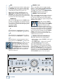
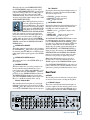
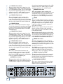
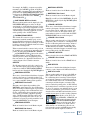
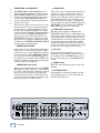
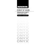
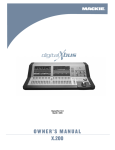
Operation Guide
POWER
INPUT
MIC
INPUT SOURCE SELECT
OL
MONITOR SELECT
8
0
4
8
DAW
MIX
24
2-TRACK
A
2-TRACK
B
PHONO
A
B
C
0 = +4dBu
PHONES
TALKBACK
STUDIO OUTS
MAX
OO
VOLUME
PHONES/
STUDIO OUTS
SOURCE
1
OO
MONO
MAX
INPUT SOURCE(S)
PHONES MIX INPUT
2
OO
MAX
OFF
ON
OO
DIM
MAX
LEVEL
OO
MUTE
MAX
LEVEL
TO
2-TRACKS
TO
PHONES/
STUDIO
STUDIO COMMAND SYSTEM
BIG KNOB
Important Safety Instructions
13. Unplug this apparatus during lightning storms or when unused for long
periods of time.
1. Read these instuctions.
2. Keep these instructions.
14. Refer all servicing to qualified service personnel. Servicing is required
when the apparatus has been damaged in any way, such as powersupply cord or plug is damaged, liquid has been spilled or objects have
fallen into the apparatus, the apparatus has been exposed to rain or
moisture, does not operate normally, or has been dropped.
3. Heed all warnings.
4. Follow all instructions.
5. Do not use this apparatus near water.
6. Clean only with dry cloth.
7. Do not block any ventilation openings. Install in accordance with the
manufacturer’s instructions.
8. Do not install near any heat sources such as radiators, heat registers,
stoves, or other apparatus (including amplifiers) that produce heat.
9. Do not defeat the safety purpose of the polarized or grounding-type
plug. A polarized plug has two blades with one wider than the other.
A grounding-type plug has two blades and a third grounding prong.
The wide blade or the third prong are provided for your safety. If the
provided plug does not fit into your outlet, consult an electrician for
replacement of the obsolete outlet.
10. Protect the power cord from being walked on or pinched particularly at
plugs, convenience receptacles, and the point where they exit from the
apparatus.
11. Only use attachments/accessories specified by the manufacturer.
12. Use only with a cart, stand, tripod, bracket, or table specified by the
manufacturer, or sold with the apparatus. When a cart is used, use
caution when moving the cart/apparatus combination to avoid injury
from tip-over.
PORTABLE CART WARNING
Carts and stands - The
Component should be used
only with a cart or stand
that is recommended by
the manufacturer.
A Component and cart
combination should be
moved with care. Quick
stops, excessive force, and
uneven surfaces may cause
the Component and cart
combination to overturn.
CAUTION
AVIS
RISK OF ELECTRIC SHOCK
DO NOT OPEN
RISQUE DE CHOC ELECTRIQUE
NE PAS OUVRIR
CAUTION: TO REDUCE THE RISK OF ELECTRIC SHOCK
DO NOT REMOVE COVER (OR BACK)
NO USER-SERVICEABLE PARTS INSIDE
REFER SERVICING TO QUALIFIED PERSONNEL
15. This apparatus has been equipped with a rocker-style AC mains power
switch. This switch is located on the rear panel and should remain
readily accessible to the user.
16. This apparatus does not exceed the Class A/Class B (whichever is
applicable) limits for radio noise emissions from digital apparatus as
set out in the radio interference regulations of the Canadian Department
of Communications.
ATTENTION — Le présent appareil numérique n’émet pas de bruits
radioélectriques dépassant las limites applicables aux appareils numériques de
class A/de class B (selon le cas) prescrites dans le réglement sur le brouillage
radioélectrique édicté par les ministere des communications du Canada.
17. Exposure to extremely high noise levels may cause permanent hearing
loss. Individuals vary considerably in susceptibility to noise-induced
hearing loss, but nearly everyone will lose some hearing if exposed to
sufficiently intense noise for a period of time. The U.S. Government’s
Occupational Safety and Health Administration (OSHA) has specified
the permissible noise level exposures shown in the following chart.
According to OSHA, any exposure in excess of these permissible limits
could result in some hearing loss. To ensure against potentially dangerous exposure to high sound pressure levels, it is recommended that all
persons exposed to equipment capable of producing high sound pressure levels use hearing protectors while the equipment is in operation.
Ear plugs or protectors in the ear canals or over the ears must be worn
when operating the equipment in order to prevent permanent hearing
loss if exposure is in excess of the limits set forth here.
Duration Per Day
In Hours
Sound Level dBA,
Slow Response
8
90
6
92
4
95
3
97
2
100
1.5
102
1
105
0.5
110
0.25 or less
115
Typical
Example
Duo in small club
Subway Train
Very loud classical music
Tami screaming at Adrian about deadlines
Loudest parts at a rock concert
ATTENTION: POUR EVITER LES RISQUES DE CHOC
ELECTRIQUE, NE PAS ENLEVER LE COUVERCLE. AUCUN
ENTRETIEN DE PIECES INTERIEURES PAR L’USAGER. CONFIER
L’ENTRETIEN AU PERSONNEL QUALIFIE.
AVIS: POUR EVITER LES RISQUES D’INCENDIE OU
D’ELECTROCUTION, N’EXPOSEZ PAS CET ARTICLE
A LA PLUIE OU A L’HUMIDITE
The lightning flash with arrowhead symbol within an equilateral
triangle is intended to alert the user to the presence of uninsulated
"dangerous voltage" within the product’s enclosure, that may be
of sufficient magnitude to constitute a risk of electric shock to persons.
Le symbole clair avec point de fl che l’int rieur d’un triangle
quilat ral est utilis pour alerter l’utilisateur de la pr sence
l’int rieur du coffret de "voltage dangereux" non isol d’ampleur
suffisante pour constituer un risque d’ l ctrocution.
The exclamation point within an equilateral triangle is intended to
alert the user of the presence of important operating and maintenance
(servicing) instructions in the literature accompanying the appliance.
Le point d’exclamation l’int rieur d’un triangle quilat ral est
employ pour alerter les utilisateurs de la pr sence d’instructions
importantes pour le fonctionnement et l’entretien (service) dans le
livret d’instruction accompagnant l’appareil.
2
BIG KNOB
WARNING — To reduce the risk of fire or
electric shock, do not expose this apparatus
to rain or moisture.
Introduction................................................................................................................4
Getting Started..........................................................................................................4
Zero the Controls .......................................................................................................................................4
Connections.................................................................................................................................................4
Set the Levels ..............................................................................................................................................5
Hookup.........................................................................................................................6
Big Knob Features......................................................................................................7
Operation Guide
Table of Contents
Front Panel...................................................................................................................................................7
Rear Panel.................................................................................................................................................... 9
Appendix A: Service Information.........................................................................13
Warranty Service...................................................................................................................................... 13
Troubleshooting....................................................................................................................................... 13
Repair ..........................................................................................................................................................14
Appendix B: Connections ...................................................................................... 15
XLR Connectors ........................................................................................................................................ 15
1/4" TRS Phone Plugs and Jacks ........................................................................................................... 15
1/4" TS Phone Plugs and Jacks.............................................................................................................. 15
RCA Plugs and Jacks................................................................................................................................. 15
Footswitch Plug and Jack....................................................................................................................... 15
Appendix C: Technical Info ...................................................................................16
Big Knob Specifications..........................................................................................................................16
Big Knob Block Diagram.........................................................................................................................18
Big Knob Limited Warranty..................................................................................19
Please write your serial number here for future
reference (i.e., insurance claims, tech support,
return authorization, etc.)
Purchased at:
Don’t forget to visit our website at
www.mackie.com for more information
about this and other Mackie products.
Date of purchase:
Part No. 0009001 Rev. B 4/04
©2004 LOUD Technologies Inc. All Rights Reserved.
Operation Guide
3
BIG KNOB
Introduction
Thank you for choosing the Mackie Big Knob,
your signal routing and monitoring solution for your
DAW-based studio. Big Knob provides a control
room matrix and the basic features of an expensive
mixer, but tailored for the requirements of your
DAW (Digital Audio Workstation) environment.
These features include selecting up to four separate
stereo input sources, monitoring through three different speakers for A/B/C comparisons, providing a
separate headphone mix and a studio output for the
talent, and a built-in talkback mic for slate-to-tape
and headphone cueing. In other words, it gives you
everything you need from a mixer, without the stuff
you don’t need!
Another important feature you’ve come to expect
from Mackie is pristine sound quality, and Big Knob
is no exception. This is studio-quality gear, and we
made sure the audio signal suffers no degradation
by passing through Big Knob. You can connect this
baby between your expensive DAW and your really
expensive studio monitors with no reservations.
Big Knob will pass the test!
Big Knob is part of the growing family of Mackie
computer recording products. Visit our website
(www.mackie.com) to learn more about these products and the solutions to your audio and recording
needs that Mackie has to offer, or pick up a catalog
at your nearest Mackie dealer.
POWER
INPUT
MIC
INPUT SOURCE SELECT
OL
MONITOR SELECT
8
0
4
8
DAW
MIX
24
2-TRACK
A
2-TRACK
B
PHONO
A
B
C
0 = +4dBu
PHONES
TALKBACK
STUDIO OUTS
MAX
OO
VOLUME
PHONES/
STUDIO OUTS
SOURCE
1
OO
MONO
MAX
INPUT SOURCE(S)
PHONES MIX INPUT
2
OO
OFF
ON
OO
LEVEL
OO
MUTE
MAX
LEVEL
TO
2-TRACKS
MAX
Getting Started
Zero the Controls
The following steps will help you set up your Big
Knob and get the levels adjusted correctly. Once you
have made the connections and adjustments, refer to
the Features section for more in-depth information
about each input, output, switch, and control knob.
1. Turn off the POWER switch
Most of the inputs and outputs on Big Knob
have either a trim control or a level switch
labeled –10 dB and +4 dB. This actually
comes from two standard operating levels
that have evolved in the audio industry:
–10 dBV consumer level and +4 dBu professional level. Most consumer equipment with RCA
connectors operate at the –10 dBV level, while most
professional equipment with 1/4-inch phone jacks
or XLR connectors operate at the +4 dBu level.
As you might expect, the +4 dBu level is higher
(louder) than the –10 dBV level, so it is important to
match the input and output levels of Big Knob to the
equipment you have connected to it. For a Big Knob
input, the –10 dB setting accepts a smaller signal
and provides more gain than the +4 dB setting. For
a Big Knob output, the –10 dB setting produces a
smaller signal than the +4 dB setting.
4
DIM
MAX
BIG KNOB
TO
PHONES/
STUDIO
on the rear panel.
2. On the front panel, turn the Big VOLUME Knob
and all the LEVEL controls all the way down
(counterclockwise).
3. Set all the switches to the up position (front
and rear panels).
4. On the rear panel, turn all the trim controls all
the way down (counterclockwise).
Connections
1. Connect the supplied detachable power cord to
the AC socket on the rear panel of Big Knob.
Set the AC SELECT switch
to the correct
position that corresponds to the AC voltage you
are using (100-120V or 220-240V).
For Monitoring:
2. Connect the audio outputs (stereo mix) from
your DAW’s audio interface to the two DAW MIX
input jacks on the rear panel of Big Knob.
Set the Levels
1. With everything off, turn on Big Knob’s POWER
switch first.
2. Turn on all other external power amplifiers, active
speakers, and headphone amplifiers.
3. Start playback on your DAW and play something you’ve already recorded (or a demo track).
You want to be able to listen to it over the monitor speakers connected to Big Knob.
4. Press the DAW MIX button in the INPUT
SOURCE SELECT section on the front panel.
The LED above the DAW MIX button should
light.
4. If you have a separate studio for recording,
connect the STUDIO OUTS to a pair of active
studio monitors (or the inputs of an amplifier that
is powering a pair of passive studio monitors).
These will be located in studio for the talent.
Set the trim control above the STUDIO OUTS
output jacks to the appropriate position, or leave
it at the –10 dBV position if you’re not sure.
5. Press the MONITOR A button in the MONITOR
SELECT section on the front panel. The LED
above the MONITOR A button should light.
6. If you know whether your DAW’s audio interface output is at a –10 dBV level (consumer) or a
+4 dBu level (pro), set the +4/–10 level switch
for the DAW MIX inputs to the appropriate position. If you don’t know, leave it out (in
the +4 dBu position). We can change it later if
we need to.
5. If you have a headphone distribution amplifier
for monitoring while recording, connect the
PHONES AMP output jacks to the inputs
of the headphone amp. Set the +4/–10 level
switch above the PHONES AMP output
jacks to the appropriate position, or leave it at
the –10 position (pushed in) if you’re not sure.
7. Slowly turn up the trim control for the DAW
MIX input until you see the meters on the
front panel lighting and dancing happily. Adjust
the control until the meters are lighting the “0”
LED regularly. You want the “+8” LED to light
only occasionally, and the “OL” LED to not light
at all.
For Recording
6. Connect the 2-TRACK A outputs to the linelevel inputs of any recording device, like a DAT
or cassette recorder. This allows you to record
from your DAW to the recorder. Set the +4/–10
level switch above the 2-TRACK A output
jacks to the appropriate position, or leave it at
the –10 position (pushed in) if you’re not sure.
8. If you can’t adjust the trim control far enough
to get the signal level up to the 0 and +5 LEDs
on the meter, turn the trim control all the way
down, push in the +4/–10 level switch for the
DAW MIX input, and slowly turn up the trim
control again. Now the signal should be strong
enough to get the 0 and +5 LEDs to light.
7. Connect the line-level outputs from the DAT or
cassette recorder to the 2-TRACK A inputs.
8. Connect the DAW output jacks on the rear
panel of Big Knob to the stereo inputs of your
DAW’s audio interface. This allows you to
record from the 2-TRACK recorder back to your
DAW. Set the +4/–10 level switch above the
DAW output jacks to the appropriate position,
or leave it at the –10 position (pushed in) if
you’re not sure.
POWER
ON
~100-240 VAC
50/60 Hz 25W
MONITOR
A
MONITOR
B
MONITOR
9. Slowly turn up the Big Knob VOLUME
control. You should begin to hear playback from
your DAW through your studio monitor speakers. Adjust the VOLUME control to a comfortable listening level. If it seems like you have to
turn up the VOLUME control all the way to hear
the monitor speakers, turn down the VOLUME
control and check to see if the trim control
OUTPUTS
C
2-TRACK
2-TRACK
A
B
STUDIO
PHONES
AMP
DAW
OUTPUT
DAW
PHONES
MIX INPUT
SOURCES
-10dB
-10dB
+4dB
-10dB
+4dB
L
+4dB
L
L
+4 dB
-10 dB
L
+4 dB
-10 dB
L
+4 dB
-10 dB
L
+4 dB
-10 dB
-10dB
+4dB
L
L
L
R
R
R
R
R
R
R
R
BAL/UNBAL
BAL/UNBAL
BAL/UNBAL
BAL/UNBAL
BAL/UNBAL
BAL/UNBAL
BAL/UNBAL
L
U
BAL/UNBAL
+10dB
-10dB
(MONO)
R
(MONO)
PHONO
R
BAL/
UNBAL
BAL/
UNBAL
+10dB
GROUND
+4dB
-10dB
L
U
-10dB
BAL/UNBAL
+4dB
-10dB
2-TRACK
B
R
BAL/
UNBAL
+10dB
DAW
MIX
R
(MONO)
+4 dB
-10 dB
-10dB
AC SELECT
220-240V
100-120V
+4dB
-10dB
2-TRACK
A
U
L
Operation Guide
3. Connect the MONITOR A output jacks on the
rear panel of Big Knob to a pair of active studio
monitors (or the inputs of an amplifier that is
powering a pair of passive studio monitors).
These will be located at your mixing position.
If you know whether the inputs to the active
studio monitors (or amplifier) accept a –10 dBV
(consumer) or +4 dBu input level, set the trim
control above the MONITOR A output jacks
to the appropriate position. Otherwise, leave it
at the –10 dBV position for now. You can connect additional speakers to the MONITOR B
and MONITOR C output jacks so you can hear
your mix through different types of speakers.
L
U
-10dB
+10dB
R
TALK BACK
FOOT
SWITCH
RIAA
DESIGNED BY MACKOIDS IN WOODINVILE, WA, USA • "BIG KNOB" & "MACKIE" ARE TRADEMARKS OF LOUD TECHNOLOGIES INC. • COPYRIGHT ©2004
Operation Guide
5
BIG KNOB
fier and check to see if the +4/–10 level switch
above the PHONES AMP output jacks
is in the –10 dB position (pushed in). If it is,
switch it to the +4 position and then turn up the
headphone volume control on the headphone
amplifier. Now it should get louder, faster.
above the MONITOR A output jacks is in
the –10 dB position (counterclockwise). If it is,
turn the control up to the +4 dB position and
then turn up the Big Knob VOLUME control.
Now it should get louder, faster.
10. If you have monitors connected to the STUDIO
OUTS , make sure the PHONES/STUDIO
OUTS SOURCE button on the front panel is
out, and the STUDIO OUTS ON/OFF button
is ON (LED above the button is lit).
13. You can connect a pair of headphones to one of
the two PHONES jacks on the front panel of
Big Knob. Slowly turn up its associated LEVEL
control to a comfortable listening level.
14. If you want to record from the DAT or cassette
player to your DAW, start playback on the DAT
or cassette connected to Big Knob.
11. Slowly turn up the STUDIO OUTS LEVEL
control on the front panel. You should begin
to hear playback from your DAW through your
studio monitor speakers. Adjust the STUDIO
OUTS LEVEL control to a comfortable listening
level. If it seems like you have to turn up the
LEVEL control all the way to hear the studio
monitor speakers, turn down the LEVEL control
and check to see if the trim control above the
STUDIO OUTS jacks is in the –10 dB position
(counterclockwise). If it is, turn the control
up to the +4 dB position and then turn up the
LEVEL control. Now it should get louder, faster.
CAUTION: See “A Cautionary Note” on the next
page to avoid creating a feedback loop through
the 2-TRACK inputs and outputs.
15. Push in the 2-TRACK A button in the INPUT
SOURCE SELECT section on the front panel
and turn off the DAW MIX button. Slowly turn
up the trim control for the 2-TRACK A input
until you see the meters on the front panel
light. Adjust the control until the meters are
lighting the “0” LED regularly. You want the
“+8” LED to light only occasionally, and the
“OL” LED to not light at all.
12. If you have a headphone distribution amplifier
connected to the PHONES AMP outputs, you
should be able to turn up the volume for each
headphone connected to the headphone amplifier and hear playback from the DAW. If it seems
like you’re not getting enough volume from the
headphone amplifier, turn down all the headphone volume controls on the headphone ampli-
16. Make sure the inputs to the DAW are selected
for recording. Start recording and the playback
from the 2-TRACK A input to Big Knob should
be recording in the DAW application. If it seems
like you’re not getting enough volume from the
2-TRACK playback, check to see if the +4/–10
level switch above the DAW output jacks
is in the –10 dB position (pushed in). If it is,
switch it to the +4 position. This will provide a
stronger signal to send to your DAW.
Hookup
MONITOR A
Passive
Studio Monitors
Headphones
MONITOR B
Mackie HR824 or other
Active Studio Monitors
MONITOR C
Powered
Subwoofer
Stereo Power
Amplifier
Reel-to-Reel
Recorder
Headphone Distribution
Amp
STUDIO MONITORS
Mackie HR824 or other
Active Studio Monitors
POWER
ON
~120-240 VAC
50/60 Hz 25W
MONITOR
A
MONITOR
B
MONITOR
OUTPUTS
C
2-TRACK
2-TRACK
A
B
+4 dB
-10 dB
+4 dB
-10 dB
STUDIO
PHONES
AMP
DAW
OUTPUT
DAW
PHONES
MIX INPUT
-10dB
+4dB
L
-10dB
+4dB
L
+4dB
L
L
L
L
+4 dB
-10 dB
L
+4 dB
-10 dB
-10dB
+4dB
SOURCES
L
L
L
AC SELECT
120V
240V
R
R
R
R
R
R
R
R
BAL/UNBAL
BAL/UNBAL
BAL/UNBAL
BAL/UNBAL
BAL/UNBAL
BAL/UNBAL
BAL/UNBAL
L
U
BAL/UNBAL
+10dB
-10dB
(MONO)
R
(MONO)
PHONO
R
BAL/
UNBAL
BAL/
UNBAL
+10dB
GROUND
+4dB
-10dB
L
U
-10dB
BAL/UNBAL
Turntable
+4dB
-10dB
2-TRACK
B
R
BAL/
UNBAL
+10dB
DAW
MIX
R
(MONO)
+4 dB
-10 dB
-10dB
100V
+4dB
-10dB
2-TRACK
A
U
-10dB
L
U
-10dB
+10dB
R
TALK BACK
FOOT
SWITCH
RIAA
DESIGNED BY MACKOIDS IN WOODINVILE, WA, USA • "BIG KNOB" & "MACKIE" ARE TRADEMARKS OF LOUD TECHNOLOGIES INC. • COPYRIGHT ©2004
Sound Card
DAT Recorder
Footswitch
LINE
OUTS
1
2
3
4
LINE
IN
MIC
IN
6
BIG KNOB
Front Panel
PHONO
INPUT SOURCE SELECT Section
These buttons turn on or off the four input signals
connected to Big Knob. Any combination of the four
inputs can be turned on at the same time, as indicated by the red LEDs above the buttons.
Turns on the signals connected to the PHONO stereo inputs.
When selected, these input sources are routed to the
MONITOR A, B, and C stereo outputs, the 2-TRACK A
and 2-TRACK B stereo outputs, the DAW stereo
outputs and, when the PHONES/STUDIO OUTS
SOURCE button is out (INPUT SOURCES), to the
PHONES AMP and STUDIO OUTS stereo outputs, and
to the PHONES 1 and 2 outputs on the front panel.
These six segment meters show the signal level of
the currently selected stereo source(es). The scale
of the six segments of the meter is:
–24, –8, –4, 0, +8, and OL (Overload), where “0” is
referenced to +4 dBu.
INPUT METERS
A Cautionary Note: When you
have a 2-track recording device
connected to both the inputs and
the outputs on Big Knob, you run
the risk of creating a feedback
loop. If the recording device is in record, record
pause, or input monitor mode, the signal can go
from the 2-TRACK outputs through the recording
device and back into the 2-TRACK inputs, creating
a circular loop that results in a terrible howl.
You must remember to turn off the 2-TRACK
INPUT SOURCE SELECT button when recording
to your 2-track recorder!
Operation Guide
Big Knob Features
VOLUME
This Big Knob adjusts the volume of the selected
input source going to the selected speaker outputs
(MONITOR A, B, and C). The VOLUME knob ONLY
affects the volume level of the monitor outputs (A,
B, and C). It does not affect the volume of the signal
going to other outputs, such as the headphone outputs, 2-TRACK outputs, or DAW outputs.
The VOLUME knob ranges from OFF (∞) to +10 dB
of gain (MAX).
MONO
Pressing this button combines the stereo signal
into a monophonic signal at the MONITOR A, B,
and C outputs. The left and right input signals are
summed and the mono signal is output at both the
left and right outputs. This lets you check for phase
problems in the stereo signal when played over a
monophonic system.
DAW MIX
Turns on the signals connected to the DAW MIX
stereo inputs.
2-TRACK A
MUTE
Turns on the signals connected to the 2-TRACK A
stereo inputs.
Press this button to mute the signal going to the
MONITOR A, B, and C outputs.
2-TRACK B
Turns on the signals connected to the 2-TRACK B
stereo inputs.
POWER
INPUT
MIC
INPUT SOURCE SELECT
OL
MONITOR SELECT
8
0
4
8
DAW
MIX
24
2-TRACK
A
2-TRACK
B
PHONO
A
B
C
0 = +4dBu
PHONES
TALKBACK
STUDIO OUTS
MAX
OO
VOLUME
PHONES/
STUDIO OUTS
SOURCE
1
OO
MONO
MAX
INPUT SOURCE(S)
PHONES MIX INPUT
2
OO
MAX
OFF
ON
OO
DIM
MAX
LEVEL
OO
MUTE
MAX
LEVEL
TO
2-TRACKS
TO
PHONES/
STUDIO
Operation Guide
7
BIG KNOB
DIM
PHONES 1 and 2
Pressing this button turns down the signal going to
the MONITOR A, B, and C outputs by 20 dB. This
lets you turn down the speakers to converse without affecting the speaker level you have set.
Note: Like the Big Knob VOLUME control, the
MONO, MUTE, and DIM buttons ONLY affect the
MONITOR A, B, and C outputs. These buttons have
no effect on the currently selected source(s) as they
are routed to the other various outputs.
POWER LED
This cool blue LED lights when the POWER switch
is turned on and Big Knob is receiving AC power. It
lets you know that Big Knob is turned on, even if no
other buttons are pressed that would light up their
associated red LED.
MONITOR SELECT
A
Press this button to route the currently selected
input source(s) to the MONITOR A output jacks.
B
Press this button to route the currently selected
input source(s) to the MONITOR B output jacks.
These 1/4-inch TRS connectors output an amplified stereo signal of either the DAW PHONES MIX
INPUT or the INPUT SOURCES
,
depending on the position of the PHONES/STUDIO
OUT SOURCE switch described below.
PHONES 1 and 2 Level Control
These rotary knobs control the volume of the stereo
signal at the PHONES 1 and 2 headphone connectors. The same signal appears at both headphone
outputs, but the volumes are adjusted independently
with these level controls.
Note: Turn down the PHONES
LEVEL controls before plugging
in your headphones. The PHONES
outputs are designed to drive
headphones to a very loud level,
so it is best to start with the LEVEL controls turned
all the way down and then turn them up SLOWLY to
a comfortable listening level. In fact, starting right
now, get in the habit of turning down the PHONES
LEVEL controls when you are done using your
headphones so you don’t plug them in later and accidentally blow out your ears!
PHONES/STUDIO OUT SOURCE Button
This button affects the stereo signal going to:
C
Press this button to route the currently selected
input source(s) to the MONITOR C output jacks.
Application Note: You can have one, two,
or all three MONITOR outputs turned
on at the same time. You could connect
MONITOR B to a pair of full-range speakers and MONITOR C to a subwoofer. Use
the MONITOR C button as a “subwoofer
IN/OUT” switch to compare the sound with and
without the subwoofer.
• Both headphone outputs (PHONES 1 and 2) on
the front panel
• The PHONES AMP output on the rear panel
• The STUDIO OUTS on the rear panel
When INPUT SOURCE(S) is selected (up), the
above outputs are fed the signal from the INPUT
SOURCE SELECT buttons. This is the same signal
that goes to the MONITOR A, B, and C outputs. In
this position, the recording engineer and the talent
can listen to the same mix (the MONITOR outs and
STUDIO/PHONES outs have the same signal).
POWER
INPUT
MIC
INPUT SOURCE SELECT
OL
MONITOR SELECT
8
0
4
8
DAW
MIX
24
2-TRACK
A
2-TRACK
B
PHONO
A
B
C
0 = +4dBu
PHONES
TALKBACK
STUDIO OUTS
MAX
OO
1
OO
MONO
MAX
INPUT SOURCE(S)
PHONES MIX INPUT
2
OO
8
VOLUME
PHONES/
STUDIO OUTS
SOURCE
MAX
BIG KNOB
OFF
ON
OO
DIM
MAX
LEVEL
OO
MUTE
MAX
LEVEL
TO
2-TRACKS
TO
PHONES/
STUDIO
TO 2-TRACKS
Pressing this momentary button illuminates the red
LED above it, activates the internal talkback MIC,
and sends its signal to the:
• 2-TRACK A output connectors
• 2-TRACK B output connectors
• DAW output connectors
Many DAW applications provide at
least four outputs through their associated I/O hardware. Two outputs
can provide the main mix, which is
connected to the DAW MIX INPUTs
on Big Knob and selected for monitoring with the DAW MIX INPUT SOURCE SELECT
button. The engineer can create a separate headphone mix for the talent in the DAW application by
using a stereo aux send routed to another pair of
outputs, which is connected to the DAW PHONES
MIX INPUT on Big Knob and routed to the STUDIO/
PHONES outputs with the PHONES/STUDIO OUT
SOURCE button.
STUDIO OUTS ON/OFF
This button turns the signal path on and off going to
the STUDIO OUTS jacks on the rear panel. When
the button is pushed in (ON), the red LED above the
button lights and the signal appears at the STUDIO
OUTS.
STUDIO OUTS LEVEL Control
This knob controls the level of the preamp for the
internal omni-directional talkback mic, as it is
routed either to the DAW and 2-TRACK A and
B outputs (when the TO 2-TRACKS button is
pressed) or to the PHONES/STUDIO bus (when the
TO PHONES/STUDIO button is pressed). The
gain of the TALKBACK LEVEL control ranges from
Off (∞) to +10 dB when turned all the way up.
A
MONITOR
B
MONITOR
Unlike all of the other buttons, the TALKBACK TO
PHONES/STUDIO and TALKBACK TO 2-TRACKS
buttons are momentary, and only activate the talkback mic as long as they are physically pressed.
SOURCES
The following section describes the connectors that
are used for various sources feeding into Big Knob.
This omni-directional microphone is located right
in Big Knob’s front panel, just to the left of the Big
VOLUME Knob. The microphone is activated when
one of the two TALKBACK assign buttons is pressed.
MONITOR
The TALKBACK TO PHONES/STUDIO button routes
the talkback signal to all of these outputs no matter
how the PHONES/STUDIO OUTS SOURCE selector button is set. This means that all the headphones
and studio outputs will hear the talkback signal
whether they are getting program material from the
INPUT SOURCE(S) or the PHONES MIX INPUT .
Rear Panel
Internal Talkback MIC
~100-240 VAC
50/60 Hz 25W
• PHONES 1 and 2 headphone outputs on the
front panel
• PHONES AMP outputs on the rear panel
• STUDIO OUTS on the rear panel
If the TALKBACK FOOTSWITCH jack on the rear
panel is activated by an external footswitch, it is the
equivalent of pressing both talkback buttons at once.
TALKBACK LEVEL
POWER
ON
Pressing this momentary button illuminates the red
LED above the button, activates the internal talkback MIC, and sends its signal to the:
Note: Both talkback buttons can be pressed at
the same time to route the talkback mic to the 2TRACK outputs and the PHONES/STUDIO outputs.
on
This controls the level at the STUDIO OUTS
the rear panel.
TO PHONES/STUDIO
2-TRACK A Inputs
These stereo 1/4-inch balanced/unbalanced inputs are
fed by the outputs of the first external 2-track recorder.
If a mono signal is plugged into the LEFT input only, it
is automatically routed to both LEFT and RIGHT inputs.
OUTPUTS
C
2-TRACK
2-TRACK
A
B
STUDIO
PHONES
AMP
DAW
OUTPUT
DAW
PHONES
MIX INPUT
SOURCES
-10dB
-10dB
+4dB
-10dB
+4dB
L
+4dB
L
L
+4 dB
-10 dB
L
+4 dB
-10 dB
L
+4 dB
-10 dB
L
+4 dB
-10 dB
-10dB
+4dB
L
L
L
R
R
R
R
R
R
R
R
BAL/UNBAL
BAL/UNBAL
BAL/UNBAL
BAL/UNBAL
BAL/UNBAL
BAL/UNBAL
BAL/UNBAL
L
U
BAL/UNBAL
+10dB
-10dB
(MONO)
R
(MONO)
PHONO
R
BAL/
UNBAL
BAL/
UNBAL
+10dB
GROUND
+4dB
-10dB
L
U
-10dB
BAL/UNBAL
+4dB
-10dB
2-TRACK
B
R
BAL/
UNBAL
+10dB
DAW
MIX
R
(MONO)
+4 dB
-10 dB
-10dB
AC SELECT
220-240V
100-120V
+4dB
-10dB
2-TRACK
A
U
L
Operation Guide
When the button is down (PHONES MIX INPUT),
the STUDIO/PHONES outputs are fed the signal
from the DAW PHONES MIX INPUT jacks on the
rear panel. In this position, the recording engineer
listens to the “real” mix coming from the DAW
(DAW MIX INPUT), but the talent can listen to an
alternate and specialized mix coming from the DAW
(DAW PHONES MIX INPUT).
L
U
-10dB
+10dB
R
TALK BACK
FOOT
SWITCH
RIAA
DESIGNED BY MACKOIDS IN WOODINVILE, WA, USA • "BIG KNOB" & "MACKIE" ARE TRADEMARKS OF LOUD TECHNOLOGIES INC. • COPYRIGHT ©2004
Operation Guide
9
BIG KNOB
2-TRACK A Level Switch
This two-position switch sets the input level of the
2-TRACK A inputs to either +4 dB (balanced input)
or –10 dB (unbalanced input). Use the +4 dB setting
for professional equipment operating at the +4 dBu
standard, and use the –10 dB setting for consumer
equipment operating at the –10 dBV standard.
2-TRACK A Trim Control
This control adjusts the input sensitivity of the
incoming 2-TRACK A signal by ±10 dB (unity at
center detent). This allows for precise level matching
between the various incoming 2-track sources, which
often do not have output level controls of their own.
2-TRACK B Inputs
These stereo 1/4-inch balanced/unbalanced inputs
are fed by the outputs of the second external 2-track
recorder. If a mono signal is plugged into the LEFT
input only, it is automatically routed to both LEFT
and RIGHT inputs.
2-TRACK B Level Switch
This two-position switch sets the input level of the
2-TRACK B inputs to either +4 dB (balanced input)
or –10 dB (unbalanced input). Use the +4 dB setting
for professional equipment operating at the +4 dBu
standard, and use the –10 dB setting for consumer
equipment operating at the –10 dBV standard.
2-TRACK B Trim Control
This control adjusts the input sensitivity of the
incoming 2-TRACK B signal by ±10 dB (unity at
center detent). This allows for precise level matching
between the various incoming 2-track sources, which
often do not have output level controls of their own.
DAW MIX
These stereo 1/4-inch balanced/unbalanced inputs are fed by the master mix output of the DAW,
usually the DAW outputs 1-2. If a mono signal is
plugged into the LEFT input only, it is automatically
routed to both LEFT and RIGHT inputs.
DAW MIX Level Switch
This two-position switch sets the input level of the
DAW MIX inputs to either +4 dB (balanced input) or
–10 dB (unbalanced input). Use the +4 dB setting
POWER
ON
~100-240 VAC
50/60 Hz 25W
MONITOR
A
MONITOR
B
MONITOR
for professional equipment operating at the +4 dBu
standard, and use the –10 dB setting for consumer
equipment operating at the –10 dBV standard.
DAW MIX Trim Control
This control adjusts the input sensitivity of the
incoming DAW MIX signal by ±10 dB (unity at center
detent). This allows you to precisely fine tune the
incoming level of the DAW MIX input so it matches
the signal level of other incoming 2-track sources.
PHONO
These stereo RCA unbalanced inputs are fed by the
outputs of a turntable with a moving-magnet cartridge
(MM). These inputs have a built-in precision RIAA
preamplifier that provides the equalization and gain
required for a phono-level signal to return it to a
proper line-level signal.
This allows you to playback vinyl records and dub
them to a 2-track recorder, as well as send the
phono signal to the input of the DAW for archiving/
restoration/CD burning.
Note: Two RCA shorting plugs are provided, which
should be plugged into the PHONO inputs when they
are not being used. This terminates the inputs and
reduces the noise floor should you accidentally push
in the PHONO INPUT SOURCE SELECT button.
PHONO Trim Control
This trim control adjusts the input sensitivity of
the incoming PHONO signal by ±10 dB. This allows
you to precisely fine tune the incoming level of the
PHONO input so it matches the signal level of other
incoming 2-track sources.
The PHONO input does not need a +4/–10 level
switch since a phonograph is always at a consumer
signal level, unlike tape decks and soundcards,
which could be –10 or +4, depending on the model.
PHONO Grounding Lug (GND)
This small grounding lug allows you to connect the
grounding wire from an attached turntable. This
prevents ground loops and hum from showing up in
the phono source’s audio signal.
DAW PHONES MIX INPUT
These stereo 1/4-inch balanced/unbalanced inputs
allow connection of a second stereo mix from the
DAW for a custom headphone mix.
OUTPUTS
C
2-TRACK
2-TRACK
A
B
STUDIO
PHONES
AMP
DAW
OUTPUT
DAW
PHONES
MIX INPUT
SOURCES
L
U
-10dB
-10dB
+4dB
L
-10dB
+4dB
L
+4dB
L
L
+4 dB
-10 dB
L
+4 dB
-10 dB
L
+4 dB
-10 dB
L
+4 dB
-10 dB
-10dB
+4dB
L
L
R
R
R
R
R
R
R
R
BAL/UNBAL
BAL/UNBAL
BAL/UNBAL
BAL/UNBAL
BAL/UNBAL
BAL/UNBAL
BAL/UNBAL
BAL/UNBAL
+10dB
(MONO)
BIG KNOB
(MONO)
R
BAL/
UNBAL
BAL/
UNBAL
+10dB
GROUND
PHONO
R
DESIGNED BY MACKOIDS IN WOODINVILE, WA, USA • "BIG KNOB" & "MACKIE" ARE TRADEMARKS OF LOUD TECHNOLOGIES INC. • COPYRIGHT ©2004
10
L
U
-10dB
+4dB
-10dB
L
U
-10dB
BAL/UNBAL
+4dB
-10dB
2-TRACK
B
R
BAL/
UNBAL
+10dB
DAW
MIX
R
(MONO)
+4 dB
-10 dB
-10dB
AC SELECT
220-240V
100-120V
+4dB
-10dB
2-TRACK
A
L
U
-10dB
+10dB
R
RIAA
TALK BACK
FOOT
SWITCH
DAW PHONES MIX Level Switch
This two-position switch sets the input level of the
DAW PHONES MIX inputs to either +4 dB (balanced input) or –10 dB (unbalanced input). Use the
+4 dB setting for professional equipment or soundcards operating at the +4 dBu standard, and use the
–10 dB setting for consumer equipment or soundcards operating at the –10 dBV standard.
TALKBACK FOOTSWITCH
This 1/4-inch TS connector accepts a standard
momentary footswitch (normally open), or a momentary handheld switch such as the Switchcraft
ED900. This allows a producer standing at a remote
location to activate the talkback circuit and communicate with recording talent.
When an external switch is connected and goes from
its “normally open” position to its “momentary closed”
position, the front panel TALKBACK TO 2-TRACKS
and TO PHONES/STUDIO buttons both activate,
their LEDs illuminate, and the talkback circuit is
activated just as if someone had physically pressed
these two buttons. See “Appendix B: Connections” for
a wiring diagram of the footswitch connection.
OUTPUTS
The following outputs are fed by the “control room
bus.” This is the signal path fed from the inputs currently selected with the INPUT SOURCE SELECT
buttons and routed through the Big VOLUME Knob.
MONITOR A OUTPUTS
These stereo 1/4-inch balanced/unbalanced outputs
connect to the first set of external speakers. You
can connect these outputs to self-powered speakers,
or to a power amplifier driving passive speakers.
MONITOR A Trim Control
This trim control adjusts the sensitivity of the
MONITOR A output signal. Use the +4 dB setting
when connecting to balanced inputs on professional
equipment operating at the +4 dBu standard, and
use the –10 dB setting when connecting to unbalanced inputs on consumer equipment operating
at the –10 dBV standard. The trim control can be
adjusted to any setting between the +4 and –10
positions if necessary to precisely match the levels
among the MONITOR A, B, and C outputs.
MONITOR B OUTPUTS
Works as described above for the Monitor A path.
MONITOR B Trim Control
MONITOR C OUTPUTS
Works as described above for the Monitor A path.
MONITOR C Trim Control
Works as described above for the Monitor A path.
Note: The overall level of the MONITOR A, B, and C
OUTPUTS is controlled by the Big VOLUME Knob
on the front panel.
2-TRACK A OUTPUTS
These stereo 1/4-inch balanced/unbalanced outputs
connect to the inputs of the first external 2-track
recorder. This could be a DAT deck, cassette deck,
reel-to-reel recorder, etc. The signal at these outputs is whatever source is selected with the INPUT
SOURCE SELECT buttons on the front panel.
Operation Guide
For example, the DAW’s 1-2 outputs can send the
main mix to the DAW MIX inputs on Big Knob,
and the DAW’s 3-4 outputs can send a custom headphone mix to the DAW PHONES MIX INPUT. You
can then use the PHONES/STUDIO OUTS SOURCE
button to select the mix for the PHONES
and STUDIO OUTS .
2-TRACK A Level Switch
This two-position switch sets the level of the 2-TRACK
A outputs to either +4 dB (out) or –10 dB (pushed in).
Use the +4 dB setting when connecting to balanced
inputs on professional equipment operating at the
+4 dBu standard, and use the –10 dB setting when
connecting to unbalanced inputs on consumer equipment operating at the –10 dBV standard.
2-TRACK B OUTPUTS
Works as described above for the 2-TRACK A OUTPUTS.
2-TRACK B Level Switch
Works as described above for the 2-TRACK A level
switch.
DAW OUTPUTS
These stereo 1/4-inch balanced/unbalanced outputs
connect to a pair of inputs on the DAW audio interface.
DAW Level Switch
This two-position switch sets the level of the DAW outputs to either +4 dB (out) or –10 dB (pushed in). Use
the +4 dB setting when connecting to balanced inputs
on professional equipment or soundcards operating at
the +4 dBu standard, and use the –10 dB setting when
connecting to unbalanced inputs on consumer equipment or soundcards operating at the –10 dBV standard.
By allowing balanced or unbalanced operation, as well
as –10 or +4 operation, on an individual basis, you can
connect any combination of professional or consumer
2-track recorders and DAW soundcards that you have
available in your arsenal of audio recording equipment.
Note: All three of the above outputs (2-TRACK A, 2-TRACK B, and
DAW) produce the signal selected
by the INPUT SOURCE SELECT
buttons on the front panel. These
outputs require no variable level output controls
(aside from the +4/–10 switches), since the connected 2-track recorders and DAW inputs typically
have their own variable input level controls.
Works as described above for the Monitor A path.
Operation Guide
11
BIG KNOB
PHONES AMP and STUDIO OUT
STUDIO OUTS
The PHONES AMP and STUDIO OUTS have the
option of being fed signal by the currently selected
INPUT SOURCE SELECT buttons (thus mirroring
the mix being heard by the engineer) or the signal
connected to the DAW PHONES MIX INPUT connectors (thus providing a separate unique monitoring mix for the talent).
Connect these stereo 1/4-inch balanced/unbalanced
connectors to a pair of active monitors (or to an
amplifier and passive monitors) in the studio performance space. This allows the performers to hear
playback without having to use headphones, and
allows the control room engineer to communicate
to the performers through the talkback system. The
STUDIO OUTS level is controlled by the STUDIO
OUTS LEVEL control on the front panel.
This allows the engineer to listen to his or her own
master mix in the control room, while allowing the
talent to listen to a customized headphone mix at
the same time through the PHONES 1 or 2 outputs
on the front panel or through an external headphone
amp connected to the PHONES AMP OUTPUT on
the rear panel, as well as the studio monitor outs
(STUDIO OUTS). The choice of which stereo signal
(current source or headphone mix input) is heard is
determined by the PHONES/STUDIO OUTS SOURCE
select button on the front panel.
STUDIO OUTS Trim Control
This trim control adjusts the sensitivity of the
STUDIO OUTS signal. Use the +4 dB setting when
connecting to balanced inputs on professional equipment operating at the +4 dBu standard, and use the
–10 dB setting when connecting to unbalanced inputs
on consumer equipment operating at the –10 dBV
standard. Although the trim control is typically set to
one side or the other, it can be adjusted to any setting
between the +4 and –10 positions if necessary.
PHONES AMP OUTPUTS
Connect these stereo 1/4-inch balanced/unbalanced
connectors to an external multi-headphone amplifier. This allows you to connect multiple sets of headphones for the talent. The PHONES AMP OUTPUT
level is not affected by the Big VOLUME Knob or
the headphone level controls on the front panel. The
headphone amplifier should have its own individual
volume controls for the headphones.
AC Socket
Connect the included detachable power cord to
this AC socket (2-prong IEC connector) on the rear
panel. Make sure the AC SELECT switch is set to
the correct AC voltage (see AC SELECT Switch
below).
POWER Switch
PHONES AMP Level Switch
This rocker style switch turns power on and off for
Big Knob.
This two-position switch sets the level of the PHONES
AMP outputs to either +4 dB (out) or –10 dB (pushed
in). Use the +4 dB setting when connecting to balanced
inputs on professional equipment operating at the
+4 dBu standard, and use the –10 dB setting when
connecting to unbalanced inputs on consumer equipment operating at the –10 dBV standard.
POWER
ON
~100-240 VAC
50/60 Hz 25W
MONITOR
A
MONITOR
B
MONITOR
AC SELECT Switch
Set this switch to the 100-120V position for 100 VAC
and 120 VAC power, and to the 220-240V position for
220 VAC and 240 VAC power.
OUTPUTS
C
2-TRACK
2-TRACK
A
B
STUDIO
PHONES
AMP
DAW
OUTPUT
DAW
PHONES
MIX INPUT
SOURCES
L
U
-10dB
-10dB
+4dB
L
-10dB
+4dB
L
+4dB
L
L
+4 dB
-10 dB
L
+4 dB
-10 dB
L
+4 dB
-10 dB
L
+4 dB
-10 dB
-10dB
+4dB
L
L
R
R
R
R
R
R
R
R
BAL/UNBAL
BAL/UNBAL
BAL/UNBAL
BAL/UNBAL
BAL/UNBAL
BAL/UNBAL
BAL/UNBAL
BAL/UNBAL
+10dB
(MONO)
BIG KNOB
(MONO)
R
BAL/
UNBAL
BAL/
UNBAL
+10dB
GROUND
PHONO
R
DESIGNED BY MACKOIDS IN WOODINVILE, WA, USA • "BIG KNOB" & "MACKIE" ARE TRADEMARKS OF LOUD TECHNOLOGIES INC. • COPYRIGHT ©2004
12
L
U
-10dB
+4dB
-10dB
L
U
-10dB
BAL/UNBAL
+4dB
-10dB
2-TRACK
B
R
BAL/
UNBAL
+10dB
DAW
MIX
R
(MONO)
+4 dB
-10 dB
-10dB
AC SELECT
220-240V
100-120V
+4dB
-10dB
2-TRACK
A
L
U
-10dB
+10dB
R
RIAA
TALK BACK
FOOT
SWITCH
Warranty Service
•
If there is no sound in the PHONES
or
STUDIO outputs:
• Make sure the PHONES/STUDIO OUTS
SOURCE button on the front panel is up
(INPUT SOURCES selected).
• Make sure the PHONES or STUDIO
Level control is turned up.
• Make sure the STUDIO OUTS ON/OFF button
is ON.
•
If there is no sound in the MONITOR OUTPUTS
:
• Make sure the correct MONITOR SELECT
button is pushed in and the trim control for the
MONITOR OUTPUT is set correctly.
• Make sure the cable connecting the MONITOR
OUTPUT to the active speaker or power amplifier isn’t defective and the amplifier/speaker
combination is working correctly.
Details concerning Warranty Service are spelled out
in the Warranty section on page 19.
If you think your Big Knob has a problem, please do
everything you can to confirm it before calling for
service. Doing so might save you from the deprivation of your Big Knob and the associated suffering.
These may sound obvious to you, but here are some
things you can check. Read on.
Troubleshooting
No Power
•
Our favorite question: Is it plugged in?
•
Make sure the power cord is securely seated in
the IEC socket and plugged all the way into
the AC outlet.
Bad Sound
•
Is the input connector plugged completely into
the jack?
•
Is it loud and distorted? Make sure the trim
control and level switch for the selected input
is set correctly. Reduce the signal level on the
input source if possible.
Is the POWER LED on the front panel illuminated? If not, make sure the AC outlet is live. If
so, refer to “No Sound” below.
•
If possible, listen to the signal with headphones
plugged into the input source device. If it sounds
bad there, it’s not Big Knob causing the problem.
•
Are all the lights out in your building? If so,
contact your local power company to get power
restored.
•
•
If the POWER LED is not illuminated, and you
are certain that the AC outlet is live, it will be
necessary to have Big Knob serviced. There are no
user serviceable parts inside. Refer to “Repair” at
the end of this section to find out how to proceed.
Make sure the trim control for the MONITOR
OUTPUT is set correctly and not overdriving the
input stage of the active speaker or amplifier to
which it is connected.
•
Make sure the AC outlet is live (check with a
tester or lamp).
•
Is the POWER switch on? Make sure the
POWER switch on the rear panel is in the ON
position (up).
•
Operation Guide
Appendix A: Service Information
Noise/Hum
•
If a turntable is connected to the PHONO
inputs on Big Knob, make sure the ground wire
from the turntable is connected to the GND
terminal on Big Knob.
•
If a turntable is not connected to the PHONO
inputs, make sure the PHONO INPUT SOURCE
SELECT button is not pushed in. Also make
sure the RCA shorting plugs are connected to
the PHONO inputs when not being used.
No Sound
•
Is the POWER LED on the front panel illuminated? If not, refer to “No Power” above.
•
Is the correct INPUT SOURCE SELECT button
selected? Make sure the LED above the INPUT
SOURCE SELECT button is lit.
•
Is the signal source turned up? Make sure the
signal level from the selected input source is
high enough to light up some of the INPUT
meter LEDs on Big Knob’s front panel.
•
Check the signal cables between the input
sources and Big Knob. Disconnect them one by
one. When the noise goes away, you’ll know
which input source is causing the problem.
•
Make sure the trim control and level switch for
the selected input are set correctly.
•
Sometimes it helps to plug all the audio equipment into the same AC circuit so they share a
common ground.
Operation Guide
13
BIG KNOB
Repair
Service for Mackie products is available at our
factory, located in sunny Woodinville, Washington.
Service for Mackie products living outside the
United States can be obtained through local dealers
or distributors.
5. Include a legible note stating your name, shipping address (no P.O. boxes), daytime phone
number, RA number, and a detailed description of
the problem, including how we can duplicate it.
If your Big Knob needs service, follow these instructions:
6. Write the RA number in BIG PRINT on top of
the box. Units sent to us without the RA number will be refused.
1. Review the preceding troubleshooting suggestions. Please.
7. Ship the Big Knob to us. We suggest insurance
for all forms of cartage. Ship to this address:
2. Call Tech Support at 1-800-898-3211, 7 am to
5 pm PST, to explain the problem and request
an RA (Return Authorization) number. Have
your Big Knob’s serial number ready. You must
have an RA number before you can obtain service at the factory.
MACKIE
SERVICE DEPARTMENT
16220 Wood-Red Road NE
Woodinville, WA 98072
3. Keep this owner’s manual and the detachable
linecord. We don’t need them to repair Big Knob.
8. We’ll try to fix the Big Knob within three to five
business days. Ask Tech Support for the latest turn-around times when you call for your
RA number. Big Knob must be packaged in its
original packing box, and must have the RA
number on the box. Once it’s repaired, we’ll ship
it back the same way in which it was received.
This paragraph does not necessarily apply to
non-warranty repair.
4. Pack Big Knob in its original package, including
endcaps and box. This is very important. When
you call for the RA number, please let Tech Support know if you need new packaging. Mackie is
not responsible for any damage that occurs due to
non-factory packaging.
Need Help?
You can reach a technical support representative
Monday through Friday
from 7 am to 5 pm PST at:
1-800-898-3211
After hours, visit www.mackie.com and click Support,
or email us at: [email protected]
14
BIG KNOB
1/4" TRS Phone Plugs and Jacks
1/4" TS Phone Plugs and Jacks
“TRS” stands for Tip-Ring-Sleeve, the three connection points available on a stereo 1/4" or balanced
phone jack or plug. TRS jacks and plugs are used
for balanced signals and stereo headphones:
“TS” stands for Tip-Sleeve, the two connection
points available on a mono 1/4" phone jack or plug.
They are used for unbalanced signals.
SLEEVE
Balanced Mono
SLEEVE
TIP
TIP
TIP
RING SLEEVE
Operation Guide
Appendix B: Connections
SLEEVE RING TIP
SLEEVE
TIP
RING
TIP
SLEEVE
1/4" TRS Balanced Mono Wiring:
Sleeve = Shield
Tip = Hot (+)
Ring = Cold (–)
RCA Plugs and Jacks
Stereo Headphones
RING SLEEVE
1/4" TS Unbalanced Wiring:
Sleeve = Shield
Tip = Hot (+)
SLEEVE RING TIP
RCA-type plugs (also known as phono plugs) and
jacks are often used in home stereo and video
equipment and in many other applications. They are
unbalanced and electrically equivalent to a 1/4" TS
phone plug.
TIP
SLEEVE
TIP SLEEVE
TIP
RING
TIP
SLEEVE
1/4" TRS Stereo Unbalanced Wiring:
Sleeve = Shield
Tip = Left
Ring = Right
RCA Unbalanced Wiring:
Sleeve = Shield
Tip = Hot (+)
Footswitch Plug and Jack
The TALKBACK FOOTSWITCH jack accepts a
1/4" TS plug. Shorting the tip and sleeve together
activates the talkback circuit. This is equivalent to
pressing the TO 2-TRACKS and TO PHONES/STUDIO buttons in the TALKBACK section.
SLEEVE
SLEEVE
TIP
TIP
TIP
SLEEVE
Handheld Switch
Operation Guide
15
BIG KNOB
Appendix C: Technical Info
Big Knob Specifications
Frequency Response
Rated Input Voltage
Line-level Inputs and Outputs
+0, –1 dB, 10 Hz to 50 kHz
+0, –3 dB, 5 Hz to 100 kHz
Line Inputs (+4 dB Level Setting)
+4 dBu/+28 dBu (nominal/maximum)
RIAA Equalization Deviation (Phono Input)
± 0.5 dB from 20 Hz to 20 kHz
Distortion (THD & IMD)
Line-level Inputs to Line-level Outputs (unity gain)
> 0.015%, 20 Hz to 20 kHz @ +4 dBu
RIAA Input, Nominal Gain
> 0.015%, 20 Hz to 20 kHz @ +4 dBu
Noise Floor
Line Inputs (–10 dB Level Setting)
–10 dBu/+14 dBu (nominal/maximum)
RIAA Input (@ 1 kHz, nominal gain)
5 mV/79 mV (nominal/maximum)
Rated Output Voltage
All Line-level Outputs (+4dB Level Setting)
+4 dBu/+22 dBu (nominal/maximum)
All Line-level Outputs (–10 dB Level Setting)
–10 dBu/+8 dBu (nominal/maximum)
(20 kHz Bandwidth, +4 dB level setting, 150Ω source)
Maximum Voltage Gain
Unity Gain, with DAW, 2-Track A, and 2-Track B Assigned
–86 dBu maximum (all outputs)
DAW, 2-Track A, and 2-Track B Input to:
Monitor A, B, and C Outputs, Studio Output, DAW, 2-Track A,
and 2-Track B Outputs
–90 dBu typical
Monitor A, B, and C Outputs
34 dB
DAW, 2-Track A, 2-Track B, and Phones Amp Outputs
24 dB
Phono Input (nominal 41.8 dB gain @ 1 kHz, inputs shorted)
–71 dBu maximum (all outputs)
Studio Output
34 dB
Equivalent Input Noise (E.I.N.)
0.89 µV / –119 dBu maximum
Phones 1 and 2 Outputs
34 dB (output loaded @ 100 kΩ)
Dynamic Range
DAW Phone Mix Input to:
Line Inputs
112 dB minimum
Phones Amp Outputs
14 dB
Phono Input
93 dB minimum
Studio Output
24 dB
Common Mode Rejection Ratio
Phones 1 and 2 Outputs
24 dB (output loaded @ 100 kΩ)
(20 Hz to 20 kHz @ +4 dB level setting)
34 dB minimum
40 dB typical
Crosstalk
Adjacent Inputs
90 dB @ 1 kHz
Left to Right/Right to Left
70 dB @ 1 kHz
Muted/Level Off
90 dB @ 1 kHz
Phono Input @ 1 kHz to:
Monitor A, B, and C Outputs
67.8 dB
DAW, 2-Track A, 2-Track B, and Phones Amp Outputs
57.8 dB
Studio Output
67.8 dB
Phones 1 and 2 Outputs
67.8 dB (output loaded @ 100 kΩ)
Input Impedance
Trim Control Range
Input Trim Controls (Center Detented)
±10 dB
Line Input
24 kΩ balanced
12 kΩ unbalanced
Output Trim Controls
–14 dB to 0 dB
Phono Input
47 kΩ || 220 pF
Dim Switch
0 dB/–20 dB
Output Impedance
Line Output
300 Ω balanced
150 Ω unbalanced
Headphone Output
150 Ω
16
BIG KNOB
Physical Dimensions
6 Segment (OL, +8 dB, 0 dB, –4 dB, –8 dB, –24 dB)
Height
Operation Guide
Input VU Meters
3.2 in/81 mm (3.5 in/89 mm with Knob)
Talkback Section
Width
Automatic Gain Control (AGC) Range
±15 dB
13.5 in/343 mm
Depth
Nominal Output Level
+4 dBu (+4 dB output level setting)
5.9 in/150 mm
Net Weight
3.5 lb/ 1.6 kg
Output Level Range
Off to +10 dB
Nominal Microphone Input Sensitivity
80 dB SPL
LOUD Technologies Inc. is always striving to improve our products by incorporating new and improved materials, components,
and manufacturing methods. Therefore, we reserve the right to
change these specifications at any time without notice.
AC Power Requirement
U.S.
Europe
Japan
Korea
120 VAC, 60 Hz
240 VAC, 50 Hz
100 VAC, 50/60 Hz
220 VAC, 60 Hz
“Mackie.”, “Big Knob,” and the “Running Man” are registered
trademarks of LOUD Technologies Inc. All other brand names
mentioned are trademarks or registered trademarks of their
respective holders, and are hereby acknowledged.
Power Consumption
25 watts
©2004 LOUD Technologies Inc. All Rights Reserved.
POWER
INPUT
MIC
INPUT SOURCE SELECT
OL
MONITOR SELECT
8
0
5.9 in/
150 mm
4
8
DAW
MIX
24
2-TRACK
A
2-TRACK
B
PHONO
A
B
C
0 = +4dBu
PHONES
TALKBACK
STUDIO OUTS
MAX
OO
VOLUME
PHONES/
STUDIO OUTS
SOURCE
1
OO
MONO
MAX
OO
DIM
MAX
OO
OFF
ON
INPUT SOURCE(S)
PHONES MIX INPUT
2
OO
MUTE
LEVEL
MAX
TO
PHONES/
STUDIO
TO
2-TRACKS
LEVEL
MAX
WEIGHT
3.5 lb/
1.6 kg
13.5 in/343 mm
~100-240 VAC
50/60 Hz 25W
3.2 in/
81 mm
POWER
ON
MONITOR
A
MONITOR
B
MONITOR
OUTPUTS
C
2-TRACK
2-TRACK
A
B
STUDIO
PHONES
AMP
DAW
OUTPUT
DAW
PHONES
MIX INPUT
SOURCES
L
U
-10dB
-10dB
+4dB
L
-10dB
+4dB
L
+4dB
L
L
+4 dB
-10 dB
L
+4 dB
-10 dB
L
+4 dB
-10 dB
L
+4 dB
-10 dB
-10dB
+4dB
L
L
R
R
R
R
R
R
R
R
BAL/UNBAL
BAL/UNBAL
BAL/UNBAL
BAL/UNBAL
BAL/UNBAL
BAL/UNBAL
BAL/UNBAL
L
U
BAL/UNBAL
+10dB
-10dB
(MONO)
R
(MONO)
PHONO
R
BAL/
UNBAL
BAL/
UNBAL
+10dB
GROUND
+4dB
-10dB
L
U
-10dB
BAL/UNBAL
+4dB
-10dB
2-TRACK
B
R
BAL/
UNBAL
+10dB
DAW
MIX
R
(MONO)
+4 dB
-10 dB
-10dB
AC SELECT
220-240V
100-120V
+4dB
-10dB
2-TRACK
A
L
U
-10dB
+10dB
R
TALK BACK
FOOT
SWITCH
RIAA
DESIGNED BY MACKOIDS IN WOODINVILE, WA, USA • "BIG KNOB" & "MACKIE" ARE TRADEMARKS OF LOUD TECHNOLOGIES INC. • COPYRIGHT ©2004
Operation Guide
17
BIG KNOB
2-TRACK B
INPUT
2-TRACK A
INPUT
DAW MIX
INPUT
18
R
R
L
+4
–10 dBV
+4
–10 dBV
+4
–10 dBV
MACKIE
BIG KNOB
BLOCK DIAGRAM
(#012604)
PHONO
GND LUG
PHONO
INPUT
L (MONO)
R
L (MONO)
R
L (MONO)
RIAA
RIAA
DAW
PHONES
MIX INPUT
+10
–10
+10
–10
+10
–10
+10
–10
R
L (MONO)
TRIM
VDC
TRIM
VDC
TRIM
VDC
TRIM
VDC
OFF
ON
OFF
ON
OFF
ON
OFF
ON
+4
–10 dBV
VDC
POWER
VU METER
0 = +4 dBVU
–24
0
–4
–8
8
CLIP
DIM
INPUT SOURCE(S)
PHONES MIX
PHONES/STUDIO
SOURCE
VOLUME
VDC
0 dB
–20 dB
TALKBACK
TO PHONES/STUDIO
TALKBACK
TO 2-TRACK
+4
–10
+4
–10
+4
–10
TALKBACK LEVEL
COMPRESSOR
STEREO
MONO
VDC
DAW
OUTPUTS
INTERNAL
TALKBACK MIC
REMOTE
TALKBACK
R
2-TRACK B
OUTPUTS
L
R
2-TRACK A
OUTPUTS
L
R
L
ON
MUTE
VDC
VDC
OFF
ON
OFF
ON
OFF
ON
OFF
ON
PHONES 2
LEVEL
PHONES 1
LEVEL
VDC
VDC
VDC
+4
–10
STUDIO OUT
LEVEL
+4
–10
+4
–10
+4
–10
+4
–10
PHONES 2
OUTPUT
PHONES 1
OUTPUT
R
PHONES AMP
OUTPUTS
L
R
L
R
L
R
L
R
L
STUDIO
OUTPUTS
MONITOR C
OUTPUTS
MONITOR B
OUTPUTS
MONITOR A
OUTPUTS
BIG KNOB
Big Knob Block Diagram
Please keep your sales receipt in a safe place.
A. LOUD Technologies Inc. warrants all materials, workmanship
and proper operation of this product for a period of three years
from the original date of purchase. If any defects are found
in the materials or workmanship or if the product fails to
function properly during the applicable warranty period, LOUD
Technologies, at its option, will repair or replace the product.
This warranty applies only to equipment sold and delivered
within the U.S. by LOUD Technologies Inc. or its authorized
dealers.
B. Failure to register online or return the product registration
card will not void the three-year warranty.
C. Service and repairs of Mackie products are to be performed
only at the factory (see D below) OR at an Authorized Mackie
Service Center (see E below). Unauthorized service, repairs, or
modification will void this warranty.
D. To obtain factory service:
1. Call Mackie Service at 800/898-3211, 7 AM to 5 PM
Monday through Friday (Pacific Time) to get a Return
Authorization (RA). Products returned without an RA number
will be refused.
2. Pack the product in its original shipping carton. If you do
not have the carton, just ask for one when you get your RA
number, and we’ll send a shipping carton out promptly. More
information on packing can be found in the Service section of
this manual. Please seal the Mackie product in a plastic bag.
3. Also include a note explaining exactly how to duplicate
the problem, a copy of the sales receipt with price and date
showing, and your return street address (no P.O. boxes or
route numbers, please!). If we cannot duplicate the problem
or establish the starting date of your Limited Warranty, we
may, at our option, charge for service time.
4. Ship the product in its original shipping carton, freight
prepaid to:
MACKIE SERVICE DEPARTMENT
16220 Wood-Red Road NE
Woodinville, WA, 98072, USA
IMPORTANT: Make sure that the RA number is plainly
written on the shipping carton.
E. To obtain service from an Authorized Mackie Service Center:
1. Call Mackie Service at 800/898-3211, 7 AM to 5 PM
Monday through Friday (Pacific Time) to get: 1) The name and
address of your nearest Authorized Mackie Service Center
and 2) A return authorization (RA). You must have an RA
number before taking your unit to a service center.
2. Make sure that you have a copy of your sales receipt from
the store where you bought the product. It is necessary to
establish purchase date and thus determine whether or not
your Mackie product is still under warranty. If you can’t find
it, the Authorized Service Center may charge you for repairs
even if your Mackie product is still covered by the Three-Year
Limited Warranty.
3. Make sure that the problem can be duplicated. If you bring
your Mackie product to an Authorized Service Center and
they can’t find anything wrong with it, you may be charged a
service fee.
Operation Guide
Big Knob Limited Warranty
4. If the Authorized Mackie Service Center is located in
another city, pack the loudspeaker in its original shipping
carton. More information on packing can be found in the
Service section of this manual.
5. Contact the Authorized Mackie Service Center to arrange
service or bring the Mackie product to them.
F. LOUD Technologies and Authorized Mackie Service Centers
reserve the right to inspect any products that may be the subject
of any warranty claims before repair or replacement is carried
out. LOUD Technologies and Authorized Mackie Service Centers
may, at their option, require proof of the original date of purchase
in the form of a dated copy of the original dealer’s invoice or
sales receipt. Final determination of warranty coverage lies solely
with LOUD Technologies or its Authorized Service Centers.
G. Mackie products returned to LOUD Technologies and deemed
eligible for repair or replacement under the terms of this
warranty will be repaired or replaced within thirty days of receipt
by LOUD Technologies. LOUD Technologies may use refurbished
parts for repair or replacement of any product. Products
returned to LOUD Technologies that do not meet the terms of
this Warranty will not be repaired and returned until payment
is received for labor, materials, return freight, and insurance.
Products repaired under warranty at the factory will be returned
freight prepaid by LOUD Technologies to any location within the
boundaries of the USA.
H. LOUD Technologies warrants all repairs performed for 90
days or for the remainder of the warranty period. This warranty
does not extend to damage resulting from improper installation,
misuse, neglect or abuse, or to exterior appearance. This
warranty is recognized only if the inspection seals and serial
number on the unit have not been defaced or removed.
I. LOUD Technologies assumes no responsibility for the quality
or timeliness of repairs performed by Authorized Mackie Service
Centers.
J. This warranty is extended to the original purchaser and to
anyone who may subsequently purchase this product within the
applicable warranty period.
K. This is your sole warranty. LOUD Technologies does
not authorize any third party, including any dealer or sales
representative, to assume any liability on behalf of LOUD
Technologies or to make any warranty for LOUD Technologies Inc.
L. THE WARRANTY GIVEN ON THIS PAGE IS THE SOLE
WARRANTY GIVEN BY LOUD TECHNOLOGIES INC. AND IS IN
LIEU OF ALL OTHER WARRANTIES, EXPRESS AND IMPLIED,
INCLUDING THE WARRANTIES OF MERCHANTABILITY AND
FITNESS FOR A PARTICULAR PURPOSE. THE WARRANTY
GIVEN ON THIS PAGE SHALL BE STRICTLY LIMITED IN
DURATION TO THREE YEARS FROM THE DATE OF ORIGINAL
PURCHASE FROM AN AUTHORIZED MACKIE DEALER. UPON
EXPIRATION OF THE APPLICABLE WARRANTY PERIOD, LOUD
TECHNOLOGIES INC. SHALL HAVE NO FURTHER WARRANTY
OBLIGATION OF ANY KIND. LOUD TECHNOLOGIES INC.
SHALL NOT BE LIABLE FOR ANY INCIDENTAL, SPECIAL, OR
CONSEQUENTIAL DAMAGES THAT MAY RESULT FROM ANY
DEFECT IN THE MACKIE PRODUCT OR ANY WARRANTY
CLAIM. Some states do not allow exclusion or limitation of
incidental, special, or consequential damages or a limitation on
how long warranties last, so some of the above limitations and
exclusions may not apply to you. This warranty provides specific
legal rights and you may have other rights which vary from state
to state.
Operation Guide
19
LOUD Technologies Inc.
16220 Wood-Red Road NE • Woodinville, WA 98072 • USA
US and Canada: 800.258.6883
Europe, Asia, Central and South America: 425.487.4333
Middle East and Africa: 31.20.654.4000
Fax: 425.487.4337 • www.mackie.com
E-mail: [email protected]