1
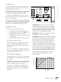
QUAD EQ
4-CHANNEL DIGITAL GRAPHIC EQUALIZER
OWNER’S MANUAL
�������
��
����
��
��
�� �������������������������
��
��
���
���
���
���
���
���
���
���
���
���
��
�����
����
��
����
�����
��
��
����
��
���
�����
���
���
���
�
��
���
�
���
��
���
� ��
���
���
���
�����
������
����
������
����
���������
�����
������
���������
����
��������������
�
��
����
��
��
��
��
���
���
���
���
���
���
���
���
���
���
��
�����
����
��
����
�����
�����
����
��
���
�����������������������������������������������������
����������������������������������������������������������������
�������������������������������������������������������������������������
��
�����
���
���
����
�
�
������
�
��
��
�
������
�
��
���������
������������������
�������
��������������
�����������
������������������������
��
�
�������
�������������
��
�
��
��
��
��
�����������������������������������������������
�������� �������������������������������������������
�������������������������������������������
�����������
���
���
���
����������������������������������������������������������������������������������������������������������
�����������������������������������������������������������������������������������������������
���
���
���
���
���
���
Quad EQ
Important Safety Instructions
13. Unplug this apparatus during lightning storms or when unused for long
periods of time.
1. Read these instructions.
2. Keep these instructions.
14. Refer all servicing to qualified service personnel. Servicing is required
when the apparatus has been damaged in any way, such as powersupply cord or plug is damaged, liquid has been spilled or objects have
fallen into the apparatus, the apparatus has been exposed to rain or
moisture, does not operate normally, or has been dropped.
3. Heed all warnings.
4. Follow all instructions.
5. Do not use this apparatus near water.
6. Clean only with dry cloth.
7. Do not block any ventilation openings. Install in accordance with the
manufacturer’s instructions.
8. Do not install near any heat sources such as radiators, heat registers,
stoves, or other apparatus (including amplifiers) that produce heat.
9. Do not defeat the safety purpose of the polarized or grounding-type
plug. A polarized plug has two blades with one wider than the other.
A grounding-type plug has two blades and a third grounding prong.
The wide blade or the third prong are provided for your safety. If the
provided plug does not fit into your outlet, consult an electrician for
replacement of the obsolete outlet.
10. Protect the power cord from being walked on or pinched particularly at
plugs, convenience receptacles, and the point where they exit from the
apparatus.
11. Only use attachments/accessories specified by the manufacturer.
12. Use only with a cart, stand, tripod, bracket, or table specified by the
manufacturer, or sold with the apparatus. When a cart is used, use
caution when moving the cart/apparatus combination to avoid injury
from tip-over.
PORTABLE CART WARNING
Carts and stands - The
Component should be used
only with a cart or stand
that is recommended by
the manufacturer.
A Component and cart
combination should be
moved with care. Quick
stops, excessive force, and
uneven surfaces may cause
the Component and cart
combination to overturn.
CAUTION
AVIS
RISK OF ELECTRIC SHOCK
DO NOT OPEN
RISQUE DE CHOC ELECTRIQUE
NE PAS OUVRIR
CAUTION: TO REDUCE THE RISK OF ELECTRIC SHOCK
DO NOT REMOVE COVER (OR BACK)
NO USER-SERVICEABLE PARTS INSIDE
REFER SERVICING TO QUALIFIED PERSONNEL
ATTENTION: POUR EVITER LES RISQUES DE CHOC
ELECTRIQUE, NE PAS ENLEVER LE COUVERCLE. AUCUN
ENTRETIEN DE PIECES INTERIEURES PAR L’USAGER. CONFIER
L’ENTRETIEN AU PERSONNEL QUALIFIE.
AVIS: POUR EVITER LES RISQUES D’INCENDIE OU
D’ELECTROCUTION, N’EXPOSEZ PAS CET ARTICLE
A LA PLUIE OU A L’HUMIDITE
The lightning flash with arrowhead symbol within an equilateral
triangle is intended to alert the user to the presence of uninsulated
"dangerous voltage" within the product’s enclosure, that may be
of sufficient magnitude to constitute a risk of electric shock to persons.
Le symbole clair avec point de fl che l’int rieur d’un triangle
quilat ral est utilis pour alerter l’utilisateur de la pr sence
l’int rieur du coffret de "voltage dangereux" non isol d’ampleur
suffisante pour constituer un risque d’ l ctrocution.
The exclamation point within an equilateral triangle is intended to
alert the user of the presence of important operating and maintenance
(servicing) instructions in the literature accompanying the appliance.
Le point d’exclamation l’int rieur d’un triangle quilat ral est
employ pour alerter les utilisateurs de la pr sence d’instructions
importantes pour le fonctionnement et l’entretien (service) dans le
livret d’instruction accompagnant l’appareil.
2
QUAD EQ
15. This apparatus shall not be exposed to dripping or splashing, and no
object filled with liquids, such as vases or beer glasses, shall be placed
on the apparatus.
16. This apparatus has been designed with Class-I construction and must
be connected to a mains socket outlet with a protective earthing connection (the third grounding prong).
17. This apparatus has been equipped with an all-pole, rocker-style AC
mains power switch. This switch is located on the rear panel and
should remain readily accessible to the user.
18. This apparatus does not exceed the Class A/Class B (whichever is
applicable) limits for radio noise emissions from digital apparatus as
set out in the radio interference regulations of the Canadian Department
of Communications.
ATTENTION — Le présent appareil numérique n’émet pas de bruits
radioélectriques dépassant las limites applicables aux appareils numériques de
class A/de class B (selon le cas) prescrites dans le réglement sur le brouillage
radioélectrique édicté par les ministere des communications du Canada.
19. Exposure to extremely high noise levels may cause permanent hearing
loss. Individuals vary considerably in susceptibility to noise-induced
hearing loss, but nearly everyone will lose some hearing if exposed to
sufficiently intense noise for a period of time. The U.S. Government’s
Occupational Safety and Health Administration (OSHA) has specified
the permissible noise level exposures shown in the following chart.
According to OSHA, any exposure in excess of these permissible limits
could result in some hearing loss. To ensure against potentially dangerous exposure to high sound pressure levels, it is recommended that all
persons exposed to equipment capable of producing high sound pressure levels use hearing protectors while the equipment is in operation.
Ear plugs or protectors in the ear canals or over the ears must be worn
when operating the equipment in order to prevent permanent hearing
loss if exposure is in excess of the limits set forth here.
Duration Per Day
In Hours
Sound Level dBA,
Slow Response
8
90
6
92
4
95
3
97
2
100
1.5
102
1
105
0.5
110
0.25 or less
115
Typical
Example
Duo in small club
Subway Train
Very loud classical music
Dave screaming at Steve about deadlines
Loudest parts at a rock concert
WARNING — To reduce the risk of fire or
electric shock, do not expose this apparatus
to rain or moisture.
Safety Instructions.................................... 2 Appendix A: Service Information.........17
Introduction................................................4
Getting Started.......................................... 5
READ THIS PAGE!!.....................................................5
Hookup Diagrams......................................6
Rear Panel Features...................................9
1. AC Input receptacle.........................................................9
2. Power switch ....................................................................9
3. Measurement Microphone input ...............................9
4. Channel TRS Inputs ........................................................9
5. Channel XLR Inputs.........................................................9
6. Channel TRS outputs .....................................................9
7. Channel XLR Outputs.....................................................9
Warranty Service.................................................... 17
Troubleshooting..................................................... 17
Repair ........................................................................18
Appendix B: Connections ...................... 19
XLR Connectors ......................................................19
1/4" TRS Phone Plugs and Jacks .........................19
1/4" TS Phone Plugs and Jacks............................19
TRS Send/Receive Inserts ...................................19
Owner’s Manual
Table of Contents
Appendix C: Technical Info ...................20
Specifications......................................................... 20
Block Diagram......................................................... 21
Controls Quick Guide............................................22
Front Panel Controls............................... 10 Quad EQ Limited Warranty.................. 23
8. LED ladders.....................................................................10
9. Master Level and Output Level Meter....................10
10. Filter select buttons and LEDs.................................10
11. MASTER select button and LED................................. 11
12. A/B/C/D buttons........................................................ 11
13. EDIT button .................................................................... 11
14. BYPASS button............................................................... 11
15. NOISE button.................................................................12
NOISE EDIT function...................................................12
16. FILTER button ................................................................13
FILTER EDIT functions.................................................13
17. RTA button..................................................................... 14
RTA EDIT functions..................................................... 14
18. MIC button.....................................................................15
MIC EDIT functions .....................................................15
19. KNOB and 20. DISPLAY .............................................. 16
21. STORE and 22. RECALL buttons ............................... 16
Quick Keys................................................................24
Don’t forget to visit our website at www.mackie.com for more
information about this and other Mackie products.
Part No. 0014679 Rev. A
©2005 LOUD Technologies Inc. All Rights Reserved.
Owner’s Manual
3
Quad EQ
Introduction
•
Built-in pink noise generator
•
RTA of input signals or mic measurement signal
•
Simultaneous EQ and RTA display
•
Variable high-pass and low-pass filters for each
channel
•
A, B, and C-weighted SPL meter
•
99 snapshots for instant recall of settings
•
Stereo Linking of channels A and B, C and D
The Quad EQ comes with its own measurement microphone, and has a built-in Sound Pressure Level (SPL)
meter, and Real Time Analyzer (RTA) functions. These
allow for simple viewing of filter settings vs. actual
measurement.
•
XLR and TRS I/O connections
•
2RU rackmount, rugged and reliable design
•
“Planet Earth” power-supply operates on voltages between 100 and 240 VAC
The simplicity of the interface makes the unit easy to
use for beginners, and fast enough for professional live
sound engineers. The sound quality makes the Quad EQ
lovely for the high-end user as well.
•
Standard IEC power receptacle and power cord
•
Slightly minty
Thank you for choosing the Quad EQ processor from
Mackie. It is part of a family of digital outboard gear
based on our TT24 digital mixer engineering developments. We thought it would be good to share the love,
not to mention the design and engineering expertise
developed during the TT24 program.
The four-channel, 30-band graphic, Adaptive-Q
equalizer has a user-friendly front panel, and a host of
features that go beyond it’s simple appearance.
The clever Adaptive-Q design allows the equalization to follow the settings of the 30 EQ filters, without
the ripple and boosting effects of common EQ units. In
other words, what you see in the display is what you get.
People are really attracted to sound engineers who
know how to operate equipment with lots of flashing
lights, so the Quad EQ was especially designed with
plenty of lights in operation.
FEATURES
•
Four 30-band, Adaptive-Q graphic equalizers
•
Algorithms developed, tuned, and trained by
Acuma Labs digital engineering group
•
Special EQ algorithm developed for accurate
representation of EQ settings
•
Unique, easy to use front panel designed for
intuitive live use
•
Measurement microphone included
Please write your serial number here for future
reference (i.e., insurance claims, tech support,
return authorization, etc.)
4
HOW TO USE THIS MANUAL
We know that many of you can’t wait to get your new
Quad EQ hooked up, and you’re probably going to use
this manual to line your cat’s litter box. Anyway...the
first section after this Introduction is a Getting Started
guide to help you get things set up fast so you can start
using it right away. Right after that are the ever popular
hook-up diagrams that show you some typical setups.
When you have time, read the Features Description
section. This describes in detail every meter, button,
and connection point on the Quad EQ. Throughout
this section you’ll find illustrations with each feature
numbered. If you want to know more about a feature,
simply locate it on the appropriate illustration, notice
the number attached to it, and find that number in the
nearby paragraphs. These complimentary numbers can
also be used as lottery or telephone numbers!
This icon marks information that is critically
important or unique to the Quad EQ. For your
own good, read them and remember them.
This icon leads you to in-depth explanations
of features and practical tips. They usually
have some valuable nuggets of information.
Appendix A is a section on troubleshooting and repair
information.
Purchased at:
Appendix B is a section on connectors: XLR connectors, TRS balanced connectors, TS unbalanced connectors, and Insert connectors.
Date of purchase:
Appendix C shows the technical specifications, and
a block diagram, hand-crafted by our block diagram
department for your pleasure. This also contains a quick
guide to the Quad EQ controls, see the back page.
QUAD EQ
Appendix D was removed after becoming bloated and
painful.
READ THIS PAGE!!
Even if you never read manuals, please
read and digest the safety instructions
on page 2, and this page before you
begin using the Quad EQ. See page 22
also, if you are in the mood.
Connections
If you already know how you want to connect the
Quad EQ, go ahead and connect the inputs and outputs
the way you want them.
The following steps show how to use the Quad EQ in a
simple stereo system using channels A and B:
1.
Turn off the power switch on the rear panel.
2.
Connect the left main mix output from a mixer into
the channel A input (XLR or TRS connectors on the
rear panel) of the Quad EQ.
3.
Connect the right main mix output from a mixer
into the channel B input (XLR or TRS connectors
on the rear panel) of the Quad EQ.
4.
Connect the channel A output of the Quad EQ to
the left main input of your powered speakers or
amplifier.
5.
Connect the channel B output of the Quad EQ to
the right main input of your powered speakers or
amplifier.
6.
Connect the supplied microphone to the MIC input
of the Quad EQ.
7.
Plug in the detachable linecord to the Quad EQ,
and connect it to a live AC outlet.
8.
Turn on your mixer and the Quad EQ.
9.
If you have powered speakers, turn them on. Otherwise, hook up your speakers to the amp and turn it
on. Adjust your powered speaker or amplifier level
controls to however the manufacturer recommends.
(This is usually all the way up.)
10. Play something into your mixer and adjust the
mixer until your speakers are playing along nicely.
The Quad EQ will have no effect if the EQ filters are
all flat. The sound system will still play, even if the
Quad EQ is off.
Measurement Microphone
1.
Position the supplied microphone in a suitable
location. For example, if you want to measure at
the front of house position, set it there on a stand,
equi-distant from the main left and right speakers.
To measure the monitors, set the mic five or six feet
away from individual monitors, or set it up equi-distant from two or more monitors.
Master Meter and Level
1.
Press CHANNEL SELECT A and B at the same time
to link these channels. Now, any changes to the EQ
or levels will affect both channels equally.
2.
As your music is playing, you will see the MASTER
LED ladder (the right-most ladder) acting as a
meter in green.
3.
To adjust the master level, press the button below
the MASTER LED ladder, and rotate the KNOB. The
level is shown in the DISPLAY, and in the MASTER
LED ladder.
Owner’s Manual
Getting Started
EQ Setting
1.
To adjust the EQ, press the buttons beneath any of
the 30 LED ladders. Then adjust the level using the
KNOB and the DISPLAY. A red LED shows the level
in the LED ladders. Be inclined to cut EQ levels
more often than boosting them.
RTA
1.
Press RTA, and the LED ladders will show the signal
levels at each filter frequency. This can help you
choose frequencies that may need EQ adjustment.
You can view the RTA analysis (green) and the EQ
settings (red single LED) at the same time. Press
RTA again to turn it off.
NOISE and MIC
1.
Press EDIT and NOISE, and adjust the noise level
using the KNOB, until pink noise is playing through
your speakers. Press the KNOB again, or EDIT to
return.
2.
Now, if you press NOISE and CHANNEL SELECT A
or B, you will hear this noise in your speakers.
3.
Press MIC, and the Quad EQ now receives signals
only from the microphone, not from your mixer.
4.
The DISPLAY shows the SPL level.
5.
Press EDIT and MIC, and adjust the KNOB until the
mic signals appear in the 30 LED ladders.
6.
Adjust the EQ levels to smooth out any bumps or
dips due to room modes, and lessen the chance of
feedback.
7.
Turn off NOISE and MIC when you are done, and
your system will be ready for the audience. The
measurements and EQ adjustments will take the
guesswork out of setting up your system, but we
can’t sell you a good set of ears. That’s illegal.
Owner’s Manual
5
Quad EQ
Hookup Diagrams
��������������
��������������
������������
���������
������������
���������
����������������
���������
�����
�
����
�����
������
�
����
�����
�
����
������
�����
�
����
������
�����
������
�
����
�����
�
������
��������
���������
����������������
���������
�
�
�
�
������
������
������
������
����
�����
�
������
�
���������
�
�
�
�
�
�
�
������
������
������
������
������
������
������
������
�
�����
�
�
�
������
������
������
������
���������
�
�
�
�
�
�
�
�
�����
����
��������
��������
���������
�
�������
�
��
���������
������������������������
�����
�����������������������������������������������������
����������������������������������������������������������������
�������������������������������������������������������������������������
��
�
��
��
��
��
�����������������������������������������������
�����������
���
���
���
���
���
���
���
����������������������������������������������������������������������������������������������������������
�����������������������������������������������������������������������������������������������
MONITORING EQ FROM AUX SENDS
QUAD EQ
�
��
��
�������� �������������������������������������������
�������������������������������������������
���
6
����
������
�
�������������
�������
��������������
�����������
�
����������
�
���������
����
������������������
�����
���������
��������
�������������
����
������
���
����
����
�����
����
�����
������
���������������
Owner’s Manual
����
����
�����������
�����
�����
������
���������������
�������
�����������
����������
����
����������
������
�����
����������
������
����������������
���������
�����
�
����
�����
������
�
����
�����
�
����
������
�����
�
����
������
�����
�
������
����
�����
�
����
������
��������
���������
�
�
�
�
������
������
������
������
�
�
���������
�
�
�
�
�
�
������
������
������
������
������
������
������
������
�����
����
�����
�
����
������
����������
�
����
������
�������
���
������
���
���������
����
�
������
�
���������
��������
�����
������
�
�
�
�
������
������
������
������
���������
������������
���������
�
�
�
�
�
�
�
�
�����
����
��������
��������
���������
������������
�������������
�
�������
�
��
�������������
������������������
���������
�������
��������������
�����������
������������������������
�����
�����������������������������������������������������
����������������������������������������������������������������
�������������������������������������������������������������������������
��
�
��
��
�
��
��
��
��
�����������������������������������������������
�������� �������������������������������������������
�������������������������������������������
�����������
���
���
���
���
���
���
���
���
���
����������������������������������������������������������������������������������������������������������
�����������������������������������������������������������������������������������������������
FRONT OF HOUSE MAIN MIX EQ
Owner’s Manual
7
Quad EQ
�����
�������
���������������
�����
�������
���������������
�����
����������
������
����
����������
������
�����
����
��
����������������
��
��
��
���������
��
���������
����������������
����������
���������
��
��
��
���������
��������������
����������
���������
��
�
�����������
�������������������������������
����������������
���������
�������������
����������
���������
�������������������������������
�������������������������������
������������������
�����������������
����������������
���������������
�������
�����������
����������
�������
�������
�������
��
��
�������
��
��
�������
�
�
�
�
�
�
�
�
����
����
����
�
�
�
�
�
�
����
����
�
����������������
���
����
���
����
����
��
���������
���
����
����
��
���������
���
����
�
����
��
����
��
���������
�
������
���
�
�
�
�
�
�
���������
�
������
���
����
�
����
�������
��������
������
���
�
�
������
���
�
�
�
�
�
�
��������
���������
�
�
�
����
������
������
������
������
���������
���������
���������
���������
�
�
����������
��������
����
�
�
�
�
�������
�����
�
�
������
������
��������
�����
�
�
�����
������
������
�������������
�
�������
�
��
�������������
������������������
���������
�������
��������������
�����������
������������������������
�����
�����������������������������������������������������
����������������������������������������������������������������
�������������������������������������������������������������������������
��
��
��
�����������������������������������������������
�����������
���
���
����������������������������������������������������������������������������������������������������������
�����������������������������������������������������������������������������������������������
STUDIO TUNING
QUAD EQ
�
��
��
�������� �������������������������������������������
�������������������������������������������
���
8
�
��
��
���
���
���
���
���
���
�����
�������
�
�������
�������������
���������
������������������
�������
��������������
�����������
������������������������
�
��
�����������������������������������������������������
����������������������������������������������������������������
�������������������������������������������������������������������������
��
��
��
��
�����������������������������������������������
�������� �������������������������������������������
�������������������������������������������
�����
�����������
���
���
���
���
���
����������������������������������������������������������������������������������������������������������
�����������������������������������������������������������������������������������������������
1. AC Input receptacle
Rear Panel Ins and Outs (channels A-D)
This is a standard 3-prong IEC power connector. Connect the detachable linecord (included in the box with
your Quad EQ) to this power receptacle, and plug the
other end of the linecord into an AC outlet.
The IN and OUT jacks will pass through
signals if the power is not applied to the
Quad EQ. For example, if your mixer’s left
main output is coming into the Quad EQ channel-A input, and the Quad EQ is off, the same signal will appear
at the channel-A output jack.
The Quad EQ has a universal power supply that can
accept any AC voltage from 100 VAC to 240 VAC.
It will work virtually anywhere in the world, including Walton-on-the-Naze, England. That’s why we call it
a “Planet-Earth” power supply! The power supply is less
susceptible to voltage sags or spikes than conventional
supplies, providing greater electromagnetic isolation
and better protection against AC line noise.
2. Power switch
Press the top edge of this rocker switch in to turn on
the Quad EQ.
Turn it off by pressing the bottom edge of the rocker
switch. Audio will still pass through even when the Quad
EQ is turned off.
3. Measurement Microphone input
This XLR-male jack is used to connect the supplied
RA-420 measurement microphone.
The microphone preamplifier circuit has been optimised to work with the supplied microphone: it has a
fixed gain setting, and 48 V phantom power is applied at
all times.
When the front panel MIC button is engaged, the
microphone signals from the measurement microphone
will enter the Quad EQ for real time analysis, and the
other inputs are disconnected and will not play through
the Quad EQ.
Owner’s Manual
Rear Panel Features
���
These inputs and outputs are line-level,
and you would normally connect them to a
mixer or line-level component in your system. Do not connect microphones or instruments directly to the inputs.
4. TRS Inputs and 5. XLR Inputs
These 1/4" TRS (tip-ring-sleeve) jacks are the inputs
for the channels. They can accept balanced TRS plugs,
or unbalanced 1/4" TS (tip-sleeve) plugs, tip hot.
The female XLR jacks are also the inputs for the channels (pin 2 hot, pin 3 cold, pin 1 shield).
For each channel, the XLR and TRS inputs are in
parallel, so you can choose either style as an input. You
can use unbalanced TS connections, but we recommend
using balanced connections wherever possible.
6. TRS outputs and 7. XLR Outputs
These 1/4" TRS jacks are the outputs for the channels.
They can accept balanced TRS plugs, or unbalanced
1/4" TS plugs, tip hot.
The male XLR jacks are also the outputs for the channels.
For each channel, the balanced XLR and TRS outputs
are in parallel, so you can choose either style of output.
Both TRS and XLR outputs can be used simultaneously.
Owner’s Manual
9
�
Quad EQ
Front Panel Controls
�������
�� �������������������������
���
��
��
��
�
�
��
��
� ��
��
����
��
��
��
��
���
���
���
���
���
���
���
���
���
���
��
�����
����
��
����
�����
��
��
����
��
���
�����
���
��
���
���
���
�����
������
����
������
����
�������
�
��
����
��
��
��
��
���
���
���
���
���
���
���
���
Filters
���
��
�����
����
��
����
�����
��
��
����
��
���
�����
���
���
����
red LED per ladder, while the RTA (green) LEDs will
actively display around the EQ setting.
The Quad EQ has thirty Adaptive-Q filters across the
audio frequency range, for each of the four channels.
Each filter can be adjusted in level from 12 dB of boost
to 12 dB of cut. The Adaptive-Q design allows the actual
equalization applied to your signal to follow the settings
you see in the display, without the ripples and gain boost
found in many common EQs. The filter frequencies are
as follows from left to right:
25 Hz
31.5
40
50
63
80
100
125
160
200
250
315
400
500
630
800
1k
1.25 k
1.6 k
2k
2.5 k
3.15 k
4k
5k
6.3 k
8k
10 k
12.5 k
16 k
20 kHz
8. FILTER LED ladders
Each LED ladder contains 11 bi-colored (green/red)
LEDs that show various settings of the Quad EQ. There
is one LED ladder per filter, and they all function in the
same way except for the right-most ladder (see MASTER [9] below).
When setting the EQ level of each filter, the LEDs
glow red. They move above the center (0 dB) line when
applied as a boost in level, and below it when applied
as a cut. Each filter is capable of ±12 dB boost and cut,
achieved by pressing the button beneath the filter of
interest, and then turning the KNOB [19].
For real time analysis (RTA) applications, the LEDs
turn green. They fill from bottom to top to show broadband frequency analysis. The LEDs show the signal
levels of each filter from the current channel. If you are
using the MIC, then the LEDs show the signal levels of
each filter from the measurement microphone.
The Quad EQ can display both the EQ setting and RTA
results simultaneously, making it an extremely unique
live sound tool. The EQ settings are displayed as a single
10
���
QUAD EQ
9. MASTER LED Ladder
The right-most LED ladder shows the master output
level setting in red, and the master output meter in
green. It is like having a master fader and master meter
in one.
The level control setting is red, with unity (0 dB) at
the center and a range of ±12 dB. The adjustment is
made by pressing the MASTER SELECT [11] switch
below this LED ladder, and turning the KNOB [19].
The green output level metering is always in view,
showing the average signal level across the complete
audio frequency range, with 0 dB at the top, to -50 dB.
This right-most ladder is more to the right than any
other ladder, and no other ladder is more right-most
than it, being all leftwards.
10. FILTER SELECT buttons and LEDs
To adjust the level of a filter, press one of these buttons, and turn the KNOB [19]. The dB level (±12) appears temporarily in the DISPLAY [20] above the KNOB.
The LED above each button illuminates when that filter
is selected.
There are different options, such as grouping filters,
setting a filter to 0 dB, and setting all filters to 0 dB:
Group filter select
Press and hold a FILTER SELECT button and press
any others to create a temporary group of filters.
These can then all be adjusted at the same time using the KNOB. The filters will maintain their relative
positions during adjustment, allowing you to keep an
EQ curve the way you like, but still boost or cut the
filters. Pressing any single FILTER SELECT button
will remove the group setting.
�
������
��
Setting a filter to 0 dB
���
��
�����
Press and hold the EDIT [13] button and any
FILTER SELECT button to return that filter to unity
(0 dB).
����
��
����
�����
��
��
����
��
���
�����
���
���
�
��
���
�
���
��
���
� ��
���
���
���
���
�����
������
����
���������
������
����
��
�����
Setting all filters to 0 dB
����
��
����
�����
��
��
����
��
���
�����
���
������
���������
��������������
�
���
�����
����
���
����
�
������
�
�
������
Owner’s Manual
��
You can also select a group of filters by holding one,
then turning the KNOB to select a band of adjacent
filters. Let go of the first one, then turn the KNOB to
adjust the level of this group.
Press and hold the EDIT [13] button and the MASTER SELECT [11] button to reset all the channel
filters to unity (0 dB).
11. MASTER SELECT button and LED
Press this button to select the main output, then turn
the KNOB [19] to adjust the main output level. The
dB reading (±12) appears temporarily in the DISPLAY
above the KNOB.
12. CHANNEL SELECT buttons A/B/C/D
These backlit buttons allow you to select the channel
to be adjusted.
There are options to link pairs in stereo, and to lock a
channel as follows:
Stereo Linking
Pressing and holding A and B at the same time will
link/unlink these channels in stereo. When linked,
the pair take on channel A’s settings.
Pressing and holding C and D at the same time will
link/unlink these channels in stereo. When linked,
the pair take on channel C’s settings.
If two channels are linked, then any changes to the
filters will affect both channels equally.
If you use the NOISE function, then the noise will be
present in both of the linked channels.
Locking a channel
Press and hold the EDIT [13] button and A, B, C or
D to lock/unlock that channel.
A channel is unlocked when the channel A-D buttons
are lit solid, and it is locked when they are blinking.
When a channel is locked, its filters cannot be edited
until it is unlocked using the same press-and-hold
method.
Function Buttons
The function buttons include RTA [17], MIC [18],
NOISE [15], FILTER [16], and EDIT [13].
These buttons have two modes of operation:
1. Pressing the RTA, MIC, and FILTER buttons
toggles them on/off (the button lights when
on). To activate the noise feature, press a channel button first (A, B, C or D), then NOISE.
2. Pressing EDIT and then any of the four functions allows deeper access to the settings of
these functions. Details below…
13. EDIT button
This button is your friend. It lets you access the extra
features of the other function buttons. Press EDIT
first, followed by a button such as RTA [17], MIC [18],
NOISE [15], or FILTER [16]. What happens then is
described in the sections below, under Noise Edit, RTA
Edit, MIC Edit, and Filter Edit. (See back cover table.)
EDIT blinks when engaged, and while it is blinking
you can jump around to any mode to make adjustments.
For example, you can adust RTA, NOISE and FILTER all
without quitting the EDIT mode.
To quit the EDIT mode, you can press EDIT again, or
press the KNOB [19] in. (Its a knob and a button, wow!)
14. BYPASS button
Press this button to bypass the currently-selected EQ
channel. The incoming signals will pass through to the
outputs of the Quad EQ, without being affected by any
changes in EQ or other controls. The button will illuminate when a channel is bypassed.
The channel will stay bypassed even when another
channel is selected, and recalled when the channel is
reselected. Press BYPASS again to leave Bypass mode.
Owner’s Manual
11
�
Quad EQ
15. NOISE button
1. Press a CHANNEL SELECT Button (A, B, C or
D) and the NOISE button, then several interesting things will happen:
•
•
���
���
��
��
�����
�����
����
The audio input to the currently-selected channel is interrupted.
Pink noise appears at the output of the Quad
EQ to play in your speaker system.
��
����
�����
��
��
����
��
���
�����
���
•
Press RTA if you want to see this noise.
•
If��you����have�����stereo-linked
channels,
��
��
����
��
���then
�����the���
noise will appear in both channels.
•
The microphone input is still live, allowing you
to use the microphone to sample the noise playing in your system. (Press Mic to do this.)
����
•
If the audience is present, you may be tarred
and feathered (unless the noise is an improvement over the band).
The default level is off, and it needs to be edited to
adjust the level of the noise (see below). Once it has
been set to a suitable level, and you follow the first step
to turn on the noise, it will turn on at the last level it
was set to.
When the noise is playing, you can use the measurement microphone to set up, analyze, and equalize your
system. You will often have NOISE and MIC selected at
the same time. The response from your microphone will
show the effect of room reflections, standing waves, and
the output characteristics of your speakers, boosting
and cutting the level across the frequency band. You can
then use the Filter buttons to adjust the EQ of problem
areas. For example, if a large level boost is present in a
certain frequency range, this area will be more susceptable to feedback. See details of the MIC button for more
information about using the measurement microphone.
The noise source also comes in very handy
for testing your system, as a quick check that
all of your speakers are working correctly.
We made it so you have to press a CHANNEL SELECT
button and then the NOISE button to have the noise
come out to play. This prevents you from accidentally
turning on the noise during a heavy thrash-speed-metal
concert, or during a memorial service for a sound engineer who turned the noise on accidentally at a similar
concert.
12
QUAD EQ
���
�
��
���
�
���
��
���
� ��
���
���
���
���
�����
������
����
���������
������
����
�����
������
���������
����
��������������
�
���
����
�
������
�
�
������
NOISE EDIT function
This function allows you to adjust the output level of
the noise generator. The default level is off, to prevent
the accidental turn-on of a hot noise signal through a
speaker system.
1. Press EDIT [13] (blinks) and then NOISE
(blinks).
2. The KNOB [19] can then be used to adjust the
level from off, to the range of –50 dB to 0 dB, as
displayed in the DISPLAY [20].
3. Press the KNOB or EDIT to exit the edit mode.
4. When you turn on the noise, it will come on at
the last level you have set.
�
This button provides you with access to the variable
high-pass and low-pass filters of the current EQ channel. Pressing the FILTER button engages and disengages
these two pass filters at their currently edited settings.
���
���
��
��
For the high-pass filter, the signal level of the frequency range below the filter frequency is attenuated by
an amount determined by the high-pass filter slope. In
other words, it rolls off the lows (less boom-boom).
�����
����
��
����
�����
��
��
����
��
���
�����
���
The
used����to reduce
low-���
����high-pass
��
���� filter
����� can
�� be ��
��
���any
�����
frequency effects such as stage rumble, or microphone
handling. In another example, you might have speakers
which do not reproduce frequencies below 60 Hz very
well. You can set the high-pass filter frequency to 60 Hz,
so your amplifiers do not receive much signal level at
frequencies below this, and do not waste power. They
will have more power reserves for the frequency range
your speakers can reproduce well.
�����
For the low-pass filter, the signal level of the frequency range above the filter frequency is attenuated
by an amount determined by the low-pass filter slope. In
other words, it rolls off the highs (less tweeter tribble).
For example, you can reduce the really high frequencies upsetting the local cat population, and protect your
tweeters at the same time.
With both of these filters, you can still adjust the EQ
levels of individual filters as desired.
To get a better idea of the effect of your filter settings,
on your audio, you may want to engage the RTA and see
what’s happening.
���
�
��
���
�
���
��
���
� ��
���
���
���
���
�����
������
����
���������
������
����
�����
������
���������
����
��������������
�
���
����
�
������
�
�
������
Owner’s Manual
�
16. FILTER button
FILTER EDIT functions
The frequency and slope of the high-pass and low-pass
filters can be adjusted as follows:
1. Press EDIT [13] (blinks) and FILTER (blinks)
to get to the first option shown in the DISPLAY
[20]. Use the KNOB [19] to adjust its parameter.
2. Each time you press FILTER, you move to the
next option to be adjusted, The options are as
follows, in the order in which they appear: HPF,
LPF, HPs and LPs.
3. Press the KNOB or EDIT to exit the edit mode.
HPF (High-pass filter frequency)
The KNOB and DISPLAY allow adjustment and
display of the HPF frequency. The range is 20 Hz to
3 kHz
LPF (Low-pass filter frequency)
The KNOB and DISPLAY allow adjustment and
display of the LPF frequency. The range is 1 kHz to
20 kHz
HPs (High-pass filter slope)
The KNOB and DISPLAY allow you to change the
high-pass filter’s slope between 12 dB and 24 dB per
octave. (This is the rate of signal attenuation for frequencies lower than the high-pass filter’s frequency.)
LPs (Low-pass filter slope)
The KNOB and DISPLAY allow you to change the
low-pass filter’s slope between 12 dB and 24 dB per
octave. (This is the rate of signal attenuation for frequencies higher than the low-pass filter’s frequency.)
Owner’s Manual
13
�
Quad EQ
���
���
��
��
17. RTA button
Pressing this button engages the real time analysis
function, and lights the button solid. The RTA looks at
the input signal of the currently-selected channel. It is
not related to the external measurement mic input. The
RTA and MIC buttons operate in an exclusive manner,
meaning only one can be active at any given time.
The 30 LED ladders display the levels of the currently
selected channel. The ladders are then like a graph of
the received signal’s frequencies from 20 Hz to 20 kHz,
split up into 30 bands, vs. the signal level of each band.
�����
�����
����
����
��
��
����
����
�����
�����
��
��
��
��
����
����
��
��
���
���
�����
�����
���
���
���
�
��
���
�
���
��
���
� ��
���
���
���
���
�����
������
����
���������
������
����
�����
������
���������
����
��������������
�
���
����
�
������
�
�
������
RTA EDIT functions
There are four options for the RTA described below:
1. Press EDIT [13] (blinks) and RTA (blinks) to
get to the first option shown in the DISPLAY
[20]. Use the KNOB [19] to adjust its parameter.
This option allows the RTA to be applied to the input
signal either pre-EQ or post-EQ.
2. Each time you press RTA, you move to the next
option to be adjusted, The options are as follows, in the order in which they appear: REF,
DCY, EQ, and EQD.
A pre-EQ RTA signal is great way to view the signal
as it enters the EQ. This can be used to see the
frequency response of the raw signal coming into the
Quad EQ.
3. Press the KNOB or EDIT to exit the edit mode.
The post-EQ setting (the factory default) is very
valuable, as the RTA will respond to filter changes.
This can be useful for graphic EQs for monitor wedge
mixes. A feedback frequency can be easily identified
and cut using the Quad EQ in this way.
REF (Reference level)
This option allows you to adjust the RTA reference
level (–60 dB to 0 dB) with the KNOB. This allows
you to get the analyzed signal into the best range for
viewing on the LED ladders.
If you turn the KNOB a little, you can press and hold
the RTA button to auto-reference level the RTA. This
will take an average of the analyzed signal and set
the reference level automatically.
DCY (RTA decay)
This option provides 4 decay settings for the RTA you
can choose with the KNOB:
14
EQ (pre/post EQ RTA analysis)
•
Off is straight metering of the signal.
•
On1 displays metering plus a peak-and-hold
function with a slow decay.
•
On2 displays metering plus a peak-and-hold
with a fast decay.
•
On3 is a peak-and-hold with no decay.
QUAD EQ
EQD (EQ display)
This option allows you to turn off the EQ filter setting display during RTA operation, so you can operate the device purely as an RTA.
Although the EQ filters are still applied to the signal,
the display only shows RTA information.
If you have turned off the EQ display with this funtion, it will still come back on for a few seconds each
time you press or adjust a filter EQ. This reminds you
what the EQ settings were, even when the display
has been turned off.
Pressing this button will engage the measurement microphone input as the source for the analysis function,
and it will light the button solid.
The gain structure for this microphone input is set for
the included measurement microphone, and 48 V phantom power is continuously applied to the input.
���
��
��
The RTA [17] and MIC buttons operate in an exclusive manner, meaning only one of the two functions can
be active at any given time.
�����
����
��
����
�����
��
��
����
��
���
�����
���
MIC EDIT functions
The MIC function has two edit functions:
1. Press EDIT [13] (blinks) and MIC (blinks) to
get to the first option (ref) in the DISPLAY. Use
the KNOB [19] to adjust its parameter.
2. Press MIC again to select the next option (SPL)
to be adjusted.
3. Press the KNOB or EDIT to exit the edit mode.
ref (MIC reference level)
This option allows you to adjust the MIC reference
level (–60 to 0 dB) with the KNOB to get the analyzed signal into the best range for viewing on the
LED ladders.
If you can see the SPL level reading, but there is no
display in the LED ladders, adjust this level to bring
it up from the depths and into view.
SPL (dB-SPL weighting)
This option allows you to choose A, B, or C weighting
for the SPL meter. Use the KNOB to scroll through
the 3 options.
“Weighting” is a curve of correction factors applied
across the frequency band to accommadate the performance and perception of the human ear.
Generally, you can think of the A-weighting as a
correction for our perception at lower SPL levels,
B-weighing for medium levels, and C-weighting for
high levels.
��
���
�
���
��
���
� ��
���
����
�� the
����MIC
�����button
��
��
����
��
���
�����
���
���
Engaging
also
turns
the DISPLAY
[20]
into a dB-Sound Pressure Level (SPL) meter. It displays
“lo” when the received SPL is under 70 dB, and ranges
between 70 and 120 dB when the signal is present.
�����
�
���
���
�����
������
����
���������
������
����
���
�����
������
���������
����
��������������
�
����
�
�
������
�
������
A-weighting: Human beans can perceive loudness
more in the mid-range frequencies than the highs
or lows, so the A-weighting curve rolls off the highs
and lows. When noise levels are specified in hearing
protection ratings for example, these are usually Aweighted, and commonly displayed as dBA.
B-weighting is similar to the A-weighting, only with
less attenuation of the lows and highs.
C-weighting is fairly flat, but with limited bandwidth.
It is often used to simulate what we perceive at high
decibel levels, and is commonly displayed as dBC.
You can switch between the settings, and gain some
insight into what is going on in your system. For
example, if a C-weighted SPL reading is much higher
than an A-weighted reading of the same system, then
there must be a fair amount of low-frequency energy
present (rolled-off more by the A-weighting than the
C). If the C and A-weighted SPL readings are similar,
then the main content must be in the mid-range.
Here is an approximate graph of the correction
curves applied to the measurements across the
frequency range.
�
����������������������
���
���
Owner’s Manual
�
18. MIC button
�
��
���
�
���
�
���
���
���
���
���
���
��
��
���
���
���
���
���
���
����
��������������
Owner’s Manual
15
Quad EQ
�����
�����
��
��
19. KNOB and 20. DISPLAY
The powerful KNOB is a 24-detent rotary encoder with
a push-button action. It will normally scroll through the
���
�
snapshot number to be stored and recalled, from num- ���
ber 1 to 99 (see STORE [21] and RECALL� � [22]). ���
���
Any function edit will temporarily take �over the���KNOB
�����
and DISPLAY while that function is being edited. The
��
���
DISPLAY shows messages of the edit options,
as well
as parameters such as filter frequency, slope, and the ����
� ��
���
number
of the
horse
or greyhound
most
likely����
to win the
��
����
��
���
�����
���
���
next race on any given day. Try it!
Additionally, engaging the MIC function turns the
DISPLAY into an SPL meter for signals received by the
���
��
����
��
���
�����
���
����
measurement
microphone.
������
����
���������
������
�����
������
���������
��������������
�
�
������
�
�
������
Pressing the KNOB exits any edit function or SPL
function, and returns operation to snapshot control.
Press and hold the KNOB to display the current software build number (b18 for example).
21. STORE and 22. RECALL buttons
The STORE function allows you to save your current
EQ settings as a “snapshot” for later recall. Only the
levels of the 30 filters are stored.
Up to 99 snapshots can be stored on the Quad EQ.
To avoid accidentally storing over a favorite snapshot,
the STORE button has to be pressed for two seconds.
Normally, the STORE light will always be illuminated
to show that a snapshot can be stored. The RECALL
button illuminates if settings have already been stored
to the displayed number. For example, if snapshots 1, 2,
3, and 4 have had settings stored to them, the RECALL
button will light whenever one of these numbers is in
the DISPLAY. When number 5 is displayed, the RECALL
button will not light, indicating that nothing is stored to
this snapshot.
When a snapshot is recalled, the STORE light will go
out, indicating that the current settings are the same as
a snapshot. If you alter any parameters, the STORE light
will come back on, indicating that the current settings
are different from a snapshot.
When a snapshot is recalled, it is only recalled to the
currently selected channel. To recall a snapshot onto a
different channel:
1. Press STORE for two seconds to store the current channel’s settings in a snapshot of your
choice.
2. Change to a different channel using the channel select buttons (A, B, C or D).
3. Find the snapshot number, then press RECALL
to paste it onto the new channel.
16
QUAD EQ
If a channel is locked, the RECALL button blinks,
indicating that the snapshot cannot be recalled to a
locked channel. The channel can be unlocked by pressing and holding both the EDIT [13] button and the
CHANNEL SELECT button (A, B, C or D).
Resetting all snapshots
Press and hold STORE and RECALL during power
up to erase all snapshots stored in memory and reset
the Quad EQ to its factory default settings.
Warranty Service
Details concerning Warranty Service are spelled out in
the Warranty section on page 23.
•
Try turning the Quad EQ off. The connections between the input and output are then joined internally, and this should allow your mixer and amps to
still play. If a channel is still missing, you may have
a bad connction cable either into or out of the Quad
EQ, or a bad mixer output or amplifier.
•
Try the same source signal in another channel, set
up exactly like the suspect channel.
If you think your Quad EQ has a problem, please do everything you can to confirm it before calling for service.
Doing so might save you from the deprivation of your
Quad EQ and the associated suffering.
These may sound obvious to you, but here are some
things you can check. Read on:
Owner’s Manual
Appendix A: Service Information
Bad Output
Troubleshooting
No Power
•
Our favorite question: Is it plugged in?
•
Make sure the power cord is securely seated in the
IEC socket and plugged all the way into the AC
outlet.
•
Are the MASTER [9] levels for the channels turned
up?
•
If it’s one of the outputs, try unplugging the others.
For example, if it’s an XLR output, try unplugging
any TRS outputs if used. If the problem goes away,
it’s not the Quad EQ.
•
If a left output is presumed dead, switch the left
and right cords at the Quad EQ end. If the problem
stays on the left side, it’s not the Quad EQ, but
maybe the left amplifier channel, a bad cord, or left
speaker.
•
Make sure the AC outlet is live (check with a tester
or lamp).
•
Make sure the rear panel POWER [2] switch is in
the ON position.
•
Is anything on the front panel illuminated? If not,
make sure the AC outlet is live.
•
Are the input and output connectors plugged completely into the jacks?
•
Are all the lights out in your town? If so, contact
your local power company to get power restored.
•
Press BYPASS [14] and listen for any improvement.
•
If nothing is illuminated, and you are certain that
the AC outlet is live, it will be necessary to have
your Quad EQ serviced. There are no user serviceable
parts inside. Refer to “Repair” on the next page to
find out how to proceed.
•
If possible, listen to the signal with headphones
plugged into the input source device or mixer. If it
sounds bad there, it’s not the Quad EQ causing the
problem.
•
Have you gone a tad overboard with the EQ settings? Cut is our friend, and boost should be used
wisely.
•
Has the band been together long?
Bad Sound
Bad Channel
•
If one channel sounds bad, try pressing BYPASS
[14] on that channel. If it improves things, carefully check your settings on that channel.
•
Look at the MASTER LED [9] ladder and check
and adjust the level if needed.
•
Check there are no extreme settings of the EQ
filters or the high-pass or low-pass filters.
•
Check that NOISE [15] is not engaged.
•
Check that MIC [18] is not engaged.
Noise/Hum
•
Turn down each channel, one by one. If the noise
disappears, it’s coming from whatever is plugged
into that channel. Check your whatever.
•
Check the signal cables between the mixer and the
Quad EQ. Disconnect them one by one. If the noise
goes away, you’ll know which input is causing the
problem.
•
Sometimes it helps to plug all the audio equipment
into the same AC circuit so they share a common
ground.
Owner’s Manual
17
Quad EQ
Repair
Service for Mackie products is available at a factoryauthorized service center. Service for Mackie products
living outside the United States can be obtained through
local dealers or distributors.
6.
Write the Service Request Number in BIG PRINT on
top of the box. Units sent without the SR number will
be refused.
7.
Tech Support will tell you where to ship the Quad
EQ for repair. We suggest insurance for all forms of
cartage.
8.
You will need to contact the authorized service center for their latest turn-around times. The Quad EQ
must be packaged in its original packing box, and
must have the Service Request Number on the box.
Once it’s repaired, the authorized service center
will ship it back by ground shipping, pre-paid (if it
was a warranty repair).
If your Quad EQ needs service, follow these instructions:
1.
Review the preceding troubleshooting suggestions.
Please.
2.
Call Tech Support at 1-800-898-3211, 7 am to 5 pm
PST, to explain the problem and request a Service
Request Number. Have your serial number ready.
You must have a Service Request Number before
you can obtain warranty service.
3.
Keep this owner’s manual and the detachable
linecord. We don’t need them to repair the Quad EQ.
4.
Pack the Quad EQ in its original package, including endcaps and box. This is VERY IMPORTANT.
Mackie is not responsible for any damage that
occurs due to non-factory packaging.
5.
Include a legible note stating your name, shipping
address (no P.O. boxes), daytime phone number,
Service Request Number, and a detailed description
of the problem, including how we can duplicate it.
Note: Under the terms of the warranty, you must ship
or drop-off the unit to an authorized service center.
The return ground shipment is covered for those
units deemed by us to be under warranty.
Note: You must have a sales receipt from
an authorized Mackie dealer for your
unit to be considered for warranty
repair.
Need Help?
You can reach a technical support representative
Monday through Friday
from 7 AM to 5 PM PST at:
1-800-898-3211
After hours, visit www.mackie.com and click Support,
or email us at: [email protected]
18
QUAD EQ
XLR Connectors
1/4" TS Phone Plugs and Jacks
The Quad EQ inputs accept 3-pin male XLR connectors. These are wired as follows, according to standards
specified by the AES (Audio Engineering Society).
“TS” stands for Tip-Sleeve, the two connection points
available on a mono 1/4" phone jack or plug. They are
used for unbalanced signals.
2
SHIELD
HOT
COLD
SHIELD
SLEEVE
TIP
TIP
1
3
SLEEVE
TIP
1
Owner’s Manual
Appendix B: Connections
SLEEVE
COLD 3
HOT
1
3
2
SHIELD
COLD
2
1/4" TS Unbalanced Wiring:
Sleeve = Shield
Tip = Hot (+)
HOT
TRS Send/Receive Inserts
XLR Balanced Wiring:
Pin 1 = Shield
Pin 2 = Hot (+)
Pin 3 = Cold (–)
1/4" TRS Phone Plugs and Jacks
“TRS” stands for Tip-Ring-Sleeve, the three connection
points available on a stereo 1/4" or balanced phone
jack or plug. TRS jacks and plugs are used for balanced
signals and stereo headphones:
Balanced Mono
RING SLEEVE
Inserts are three-conductor 1/4" TRS phone plugs at
one end, and two TS phone plugs the other. They are
unbalanced, but have both the mixer output (send) and
mixer input (return) signals in one connector. If your
mixer allows these connections, this is a very handy way
of connecting your Quad EQ. (The hookup digrams show
some examples.)
The sleeve is the common ground (earth) for both signals. The send from the mixer to the input of the Quad
EQ is carried on the tip, and the return from the output
of the Quad EQ to the mixer is on the ring.
SLEEVE RING TIP
tip
TIP
ring
SEND to processor
sleeve
(TRS plug)
“tip”
RING
TIP
SLEEVE
1/4" TRS Balanced Mono Wiring:
Sleeve = Shield
Tip = Hot (+)
Ring = Cold (–)
this plug connects to one of the
mixer’s Channel Insert jacks.
“ring”
RETURN from processor
Owner’s Manual
19
Quad EQ
Appendix C: Technical Info
Specifications
Frequency Response
Analog Outputs:
15 Hz-20 kHz ±0.2 dB
Connectors:
THD
Max output level: +22 dBu balanced, +20 dBu unbalanced
Impedance:
0.01% (15 Hz-20 kHz)
150 ohms
D/A:
Signal to Noise Ratio
Analog in to Analog out, ref to +4 dBu: 104 dB
Propagation delay
3.2 mS
EQ filters
24-bits (20-20 kHz, +/-1 dB)
Dynamic Range:
108 dB
Crosstalk:
–115 dB @ 1 kHz
Sample Rates:
48 kHz
Digital Signal Processing:
30 Adaptive-Q filters, ±12 dB range
HPF
20 Hz -3 kHz, 12 or 24 dB/octave Linkwitz-Riley
LPF
1 kHz-20 kHz, 12 or 24 dB/octave Linkwitz-Riley
Analog inputs:
Connectors:
XLR female & TRS
Max input level:
+22 dBu
Input level range: ±15 dB digital trim
Impedance:
XLR male & TRS
Power:
100-240 VAC, 50/60 Hz auto-switching
Dimensions:
Width
19 inches (483 mm)
Height
3.5 inches (88 mm)
Depth
10.7 inches (271 mm)
Weight: 10 lbs (4.6 kg)
10k ohms
A/D:
LOUD Technologies Inc. is always striving to improve our products by incorporating new and improved materials, components,
and manufacturing methods. Therefore, we reserve the right to
change these specifications at any time without notice.
24-bits (20 Hz-20 kHz, ±1 dB)
Dynamic Range:
106 dB
Crosstalk:
–110 dB @ 1 kHz
Connector:
XLR female
“Mackie,” and the “Running Man” are registered trademarks of
LOUD Technologies Inc. All other brand names mentioned are
trademarks or registered trademarks of their respective holders, and are hereby acknowledged.
Gain:
Fixed at appropriate level for supplied Mic
©2005 LOUD Technologies Inc. All Rights Reserved.
Impedance:
10k ohms
Phantom Power:
48 V applied continuously
Measurement mic input
��������
�����
���������������
��������������
QUAD EQ
��������������
������
������
������
��������������
��������������
20
32-bit floating point
�����������
�������������������
�
��������
����������� �
�
���������
�������
���
�������������
��������
����������
�����
���������
�
��������
���������� �
�
�������
���
���
����������
���������
������
��
���
����
����������
�������
�����
���
���
���
�����
���������
������
���������
���
�������
�
�
��������
������
���� �����
�������������
�������
�
���
���� �����
���
�
�����
�����
���
���
���
�
����������
�����
���������������
������
��������
�������������
������
�����
�������
��
���
������������
�����
���������
����
�
�
�
��������������
�����������
�����
���������
��������
�����������
�������
Owner’s Manual
�
Block Diagram
Owner’s Manual
21
Quad EQ
Controls quick guide (copy this page onto a white tee-shirt)
The RTA, MIC, NOISE, and FILTER buttons have two
modes of operation:
1. Pressing these buttons will toggle them on or
off. Hold A, B, C, or D and NOISE to play noise.
2. Pressing EDIT and then any of these four functions will allow deeper access to the settings of
these functions, and both the function button
and EDIT will blink.
3. To quit the EDIT mode, press EDIT again, or
press the KNOB inwards.
Filter EQ Operations
OPERATION
Step 1
Step 2
Change a
Filter’s EQ
Level
Press a Filter
Select button
(blinks)
Rotate KNOB to
adjust the
dB level
Group
Filter Select
(method 1)
Hold a Filter
Select button
Press multiple
Rotate KNOB
Filter buttons,
to adjust level
then let go of first of this group
Group
Filter Select
(method 2)
Hold a Filter
Select button
Rotate KNOB to
Rotate KNOB
select a band,
to adjust level
then let go of first of this group
Set a Filter to Hold EDIT
0 dB
Press Filter
Select button
Set all
Hold EDIT
Filters to 0 dB
Press MASTER
Select button
Step 3
OPERATION
Step 1
Select a
Channel
Press Channel
A, B, C or D
Stereo Link
A and B
Hold Channel A
and B
Repeat to
unlink
Stereo Link
C and D
Hold Channel C
and D
Repeat to
unlink
Lock a Channel
Hold EDIT
Press Channel A,
B, C or D
Blinking when
locked
Unlock a
Channel
Hold EDIT
Press Channel
Select A, B, C
or D
Light solid
when not
locked
Bypass a
Channel
Press BYPASS
Notes
Step 1
Press again to
un-bypass
Step 2
Step 3
Engage FILTER Press FILTER
Adjust FILTER
HP Frequency
22
Press FILTER
Rotate KNOB
to adjust HPF
Adjust FILTER
LP Frequency
Press FILTER
again
Rotate KNOB
to adjust LPF
Change FILTER
HP Slope
Press FILTER
again
Rotate KNOB
choose slope
Change FILTER
LP Slope
Press FILTER
again
Rotate KNOB
choose slope
QUAD EQ
Press EDIT
Step 1
Step 2
Engage NOISE
Hold Channel
A, B, C or D
Press NOISE Listen to noise
Use RTA to see
Adjust NOISE
Press EDIT
Press NOISE Rotate KNOB
Step 3
RTA Operations
OPERATION
Step 1
Step 2
Step 3
Engage RTA
Press RTA
Adjust RTA
Level
Press EDIT
(blinks)
Press RTA
Rotate KNOB
to adjust level
Adjust RTA
Decay settings
Press RTA
x2
Rotate KNOB
4 options:
OFF, On1,
On2 and On3
Adjust RTA to
be Pre or Post
EQ
Press RTA
x3
Rotate KNOB
2 options:
Post or Pre
Turn off EQ display and show
RTA only
Press RTA
x4
Rotate KNOB
2 options:
On or Off
Step 3
OPERATION
Step 1
Step 2
Engage MIC
Press MIC
See SPL
Adjust MIC
Level to view
Press EDIT
(blinks)
Press MIC
Rotate KNOB
to adjust level
Press MIC
x2
Rotate KNOB
3 options:
A, B or C
weighting
Choose SPL
Noise Weighting
FILTER Operations (high or low-pass)
OPERATION
OPERATION
MIC Operations
Channel Operations
Step 2
NOISE Operations
STORE and RECALL Operations
OPERATION
Step 1
Step 2
Store current
settings as a
snapshot
Rotate KNOB to
find a suitable
number
Hold STORE for
two seconds
Recall a snapshot to become
the current
settings
Rotate KNOB to Press RECALL
find the number
of a previous
snapshot
ERASE all
snapshots
Hold STORE
and RECALL
during power up
See if a snap- Rotate KNOB
shot is saved in
a location
RECALL will
light if a snapshot has been
saved
Apply a snapshot from one
channel to
another
Rotate KNOB to
find the number
of a previous
snapshot
Change channel
by pressing a
Channel button
A, B, C or D
Step 3
Press
RECALL
Please keep your sales receipt in a safe place.
A. LOUD Technologies Inc. warrants all materials,
workmanship and proper operation of this product for a period
of two years from the original date of purchase. If any defects
are found in the materials or workmanship or if the product
fails to function properly during the applicable warranty
period, LOUD Technologies, at its option, will repair or replace
the product. This warranty applies only to equipment
sold and delivered within the U.S. by LOUD
Technologies Inc. or its authorized dealers.
B. Failure to register online or return the product registration
card will not void the two-year warranty.
C. Service and repairs of Mackie products are to be
performed only at a factory-authorized facility (see D below).
Unauthorized service, repairs, or modification will void this
warranty. To obtain repairs under warranty, you must have a
copy of your sales receipt from the authorized Mackie dealer
where you purchased the product. It is necessary to establish
the purchase date and determine whether your Mackie
product is within the warranty period.
D. To obtain factory-authorized service:
1. Call Mackie Technical Support at 800/898-3211, 7
AM to 5 PM Monday through Friday (Pacific Time) to get
a Service Request Number. Products returned without a
Service Request Number will be refused.
2. Pack the product in its original shipping carton. Also
include a note explaining exactly how to duplicate the
problem, a copy of the sales receipt with price and date
showing, and your return street address (no P.O. boxes or
route numbers, please!). If we cannot duplicate the problem
or establish the starting date of your Limited Warranty, we
may, at our option, charge for service time.
3. Ship the product in its original shipping carton, freight
prepaid to the authorized service center. The address of
your closest authorized service center will be given to you
by Technical Support, or from our website.
IMPORTANT: Make sure that the Service Request
Number is plainly written on the shipping carton.
No receipt: no warranty service.
E. LOUD Technologies reserves the right to inspect any
products that may be the subject of any warranty claims before
repair or replacement is carried out. LOUD Technologies may,
at our option, require proof of the original date of purchase in
the form of a dated copy of the original dealer’s invoice or sales
receipt. Final determination of warranty coverage lies solely
with LOUD Technologies.
F. Any products returned to one of the LOUD Technologies
factory-authorized service centers, and deemed eligible for
repair or replacement under the terms of this warranty will
be repaired or replaced within thirty days of receipt. LOUD
Technologies and its authorized service centers may use
refurbished parts for repair or replacement of any product.
Products returned to LOUD Technologies that do not meet
the terms of this Warranty will not be repaired unless
payment is received for labor, materials, return freight,
and insurance. Products repaired under warranty will be
returned freight prepaid by LOUD Technologies to any
location within the boundaries of the USA.
G. LOUD Technologies warrants all repairs performed
for 90 days or for the remainder of the warranty period.
This warranty does not extend to damage resulting from
improper installation, misuse, neglect or abuse, or to
exterior appearance. This warranty is recognized only if
the inspection seals and serial number on the unit have not
been defaced or removed.
H. LOUD Technologies assumes no responsibility for the
quality or timeliness of repairs performed by an authorized
service center.
I. This warranty is extended to the original purchaser and to
anyone who may subsequently purchase this product within
the applicable warranty period. A copy of the original sales
receipt is required to obtain warranty repairs.
J. This is your sole warranty. LOUD Technologies does not
authorize any third party, including any dealer or sales
representative, to assume any liability on behalf of LOUD
Technologies or to make any warranty for LOUD Technologies
Inc.
K. THE WARRANTY GIVEN ON THIS PAGE IS THE SOLE
WARRANTY GIVEN BY LOUD TECHNOLOGIES INC.
AND IS IN LIEU OF ALL OTHER WARRANTIES, EXPRESS
AND IMPLIED, INCLUDING THE WARRANTIES OF
MERCHANTABILITY AND FITNESS FOR A PARTICULAR
PURPOSE. THE WARRANTY GIVEN ON THIS PAGE
SHALL BE STRICTLY LIMITED IN DURATION TO TWO
YEARS FROM THE DATE OF ORIGINAL PURCHASE
FROM AN AUTHORIZED MACKIE DEALER. UPON
EXPIRATION OF THE APPLICABLE WARRANTY PERIOD,
LOUD TECHNOLOGIES INC. SHALL HAVE NO FURTHER
WARRANTY OBLIGATION OF ANY KIND. LOUD
TECHNOLOGIES INC. SHALL NOT BE LIABLE FOR ANY
INCIDENTAL, SPECIAL, OR CONSEQUENTIAL DAMAGES
THAT MAY RESULT FROM ANY DEFECT IN THE MACKIE
PRODUCT OR ANY WARRANTY CLAIM. Some states do
not allow exclusion or limitation of incidental, special,
or consequential damages or a limitation on how long
warranties last, so some of the above limitations and
exclusions may not apply to you. This warranty provides
specific legal rights and you may have other rights which
vary from state to state.
Owner’s Manual
Owner’s Manual
Quad EQ Limited Warranty
23
Quad EQ Quick Keys
EQ
Noise
CHANGE AN EQ LEVEL
START NOISE in Ch. A
hold
A
+
NOISE
EDIT
+
NOISE
1.25k
GROUP-ADJUST EQs
hold
1.25k
RESET AN EQ TO 0 dB
RESET ALL EQS TO 0 dB
hold
hold
EDIT
EDIT
+
+
+
1.5k
+
MSTR
A
STEREO LINK A and B
hold
A
+ hold
B
STEREO-LINK C and D
hold
C
+ hold
D
LOCK A CHANNEL
hold
EDIT
BYPASS A CHANNEL
+
ENGAGE RTA
RTA
ADJUST RTA LEVEL
EDIT
+
RTA
CHOOSE DECAY
EDIT
+
RTA
X2
CHOOSE PRE OR POST EQ
EDIT
+
RTA
X3
TURN OFF EQ DISPLAY
EDIT
+
RTA
X4
MIC
A
ENGAGE MIC
MIC
ADJUST MIC LEVEL
EDIT
+
MIC
CHOOSE SPL WEIGHTING
EDIT
+
MIC
BYPASS
Filter
ENGAGE FILTER
2k
RTA
1.25k
Channel
SELECT CHANNEL A
ADJUST NOISE LEVEL
X2
FILTER
ADJUST FILTER HP FREQ
EDIT
+
FILTER
ADJUST FILTER LP FREQ
EDIT
+
FILTER
X2
ADJUST FILTER HP SLOPE
EDIT
+
FILTER
X3
ADJUST FILTER LP SLOPE
EDIT
+
FILTER
X4
16220 Wood-Red Road NE • Woodinville, WA 98072 • USA
United States and Canada: 800.898.3211
Europe, Asia, Central and South America: 425.487.4333
Middle East and Africa: 31.20.654.4000
Fax: 425.487.4337 • www.mackie.com
E-mail: [email protected]