1
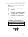
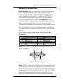
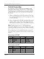
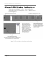
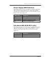
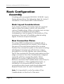
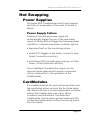
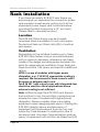
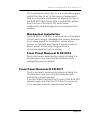
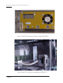
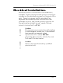
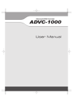
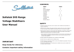
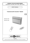
Reference Manual
R FR 5010 / R FR 5011
Series 5000
CardModule
Series 5000 Rack Frame
© LYNX Technik AG
Brunnenweg 3
64331 Weiterstadt
Germany
www.lynx-technik.com
Ver 2.0
Reference Manual R FR 5010 Version1.4
Information in this document is subject to change without
notice. No part of this document may be reproduced or
transmitted in any form or by any means, electronic or
mechanical for any purpose, without express written permission
of LYNX Technik AG.
LYNX Technik AG may have patents, patent applications,
trademarks, copyrights or other intellectual property rights
covering the subject matter in this document. Except as
expressly written by LYNX Technik AG, the furnishing of this
document does not give you any license to patents,
trademarks, copyrights or other intellectual property of LYNX
Technik AG or any of its affiliates.
© LYNX Technik AG 2002-2005 all rights reserved
Page 2
Reference Manual R FR 5010 Version1.4
WARNING
Electrical supplies in excess of 50 (fifty) volts peak value
are potentially hazardous or lethal. AC supplies between
100 and 250 peak volts exist within the rack frame chassis
when connected to AC power.
Only qualified personnel should service the rack frame
assembly.
Removal of technical earth may render the equipment
dangerous and intentional removal is prohibited.
This unit has to be separated from mains by disconnecting
the power supply cords.
This unit may have two power supplies and two power
supply cords. Disconnect all power supply cords before
servicing to avoid electric shock.
DOUBLE POLE / NEUTRALE FUSING
After operation of the fuse, parts of equipment that remain
energized might represent a hazard during servicing.
For continued protection against risk of fire, replace only
with same type and rating of fuse.
F1 .. F4: T2AH250V
Replacement AC fuses must be of the specified type and
rating: F1 .. F4: T2AH250V
The use of repaired fuses or shorting links is to be avoided.
WARNING! CAUTION!
Page 3
Reference Manual R FR 5010 Version1.4
WARNUNG!
Wenn das Gerät an das Wechselstromnetz angeschlossen
ist, treten innerhalb des Gerätes Wechselspannungen
zwischen 100 und 250 V auf, die potentiell gefährlich oder
tödlich sein können. Deshalb darf Reparatur und
Instandhaltung nur von qualifiziertem Personal
durchgeführt werden.
Das Entfernen des Schutzleiters kann das Gerät in einen
gefährlichen Zustand bringen, vorsätzliches Entfernen des
Schutzleiters ist verboten.
Das Gerät ist durch Abziehen der Netzstecker vom Netz zu
trennen.
Das Gerät kann 2 Netzgeräte mit 2 Netzkabeln haben. Vor
Servicearbeiten müssen alle Netzkabel abgezogen werden,
um elektrischen Schlag zu vermeiden.
Die Netzzuführung ist 2-polig abgesichert. Nach Ausfall
einer Sicherung können Teile der Schaltung weiter unter
Spannung bleiben und bei Servicearbeiten zu Gefahren
führen.
Vor Servicearbeiten Stromversorgung unterbrechen und
Teile vor Berührung prüfen.
Um Schutz gegen Feuer aufrechtzuerhalten, sind bei
Sicherungswechsel nur Sicherungen des gleichen Typs mit
gleichen Daten zulässig.
F1 .. F4: T2AH250V
Page 4
Reference Manual R FR 5010 Version1.4
This Page is intentionally left blank
Page 5
Reference Manual R FR 5010 Version1.4
Warranty
LYNX Technik AG warrants that the product will be free from
defects in materials and workmanship for a period of two (2)
years from the date of shipment. If this product proves defective
during the warranty period, LYNX Technik AG at its option will
either repair the defective product without charge for parts and
labor, or will provide a replacement in exchange for the
defective product.
In order to obtain service under this warranty, customer must
notify LYNX Technik of the defect before expiration of the
warranty period and make suitable arrangements for the
performance of service. Customer shall be responsible for
packaging and shipping the defective product to the service
center designated by LYNX Technik, with shipping charges
prepaid. LYNX Technik shall pay for the return of the product to
the customer if the shipment is within the country which the LYNX
Technik service center is located. Customer shall be responsible
for payment of all shipping charges, duties, taxes and any other
charges for products returned to any other locations.
This warranty shall not apply to any defect, failure, or damage
caused by improper use or improper or inadequate
maintenance and care. LYNX Technik shall not be obligated to
furnish service under this warranty a) to repair damage resulting
from attempts by personnel other than LYNX Technik
representatives to install, repair or service the product; b) to
repair damage resulting from improper use or connection to
incompatible equipment; c) to repair any damage or
malfunction caused by the use of non LYNX Technik supplies; or
d) to service a product which has been modified or integrated
with other products when the effect of such modification or
integration increases the time or difficulty servicing the product.
THIS WARRANTY IS GIVEN BY LYNX TECHNIK WITH RESPECT TO THIS
PRODUCT IN LIEU OF ANY OTHER WARRANTIES, EXPRESS OR
IMPLIED. LYNX TECHNIK AND ITS VENDORS DISCLAIM ANY IMPLIED
WARRANTIES OF MERCHANTABILITY OR FITNESS FOR A PARTICULAR
PURPOSE. LYNX TECHNIK`S RESPONISIBILITY TO REPAIR AND
REPLACE DEFECTIVE PRODUCTS IS THE SOLE AND EXCLUSIVE
REMEDY PROVIDED TO THE CUSTOMER FOR BREACH OF THIS
WARRANTY. LYNX TECHNIK AND ITS VENDORS WILL NOT BE LIABLE
FOR ANY INDIRECT, SPECIAL, INCIDENTAL, OR CONSEQUENTAL
DAMAGES IRRESPECTIVE OF WHETHER LYNX TECHNIK OR THE
VENDOR HAS ADVANCE NOTICE OF THE POSSIBILITY OF SUCH
DAMAGES.
Page 6
Reference Manual R FR 5010 Version1.4
Regulatory information
Europe
Declaration of Conformity
We
LYNX Technik AG
Brunnenweg 3
D-64331 Weiterstadt
Germany
Declare under our sole responsibility that the product
TYPE: R FR 5010 / R FR 5011
To which this declaration relates is in conformity with the following
standards (Environments E1-E3):
EN 55103-1 /1996
EN 55103-2 /1996
EN 60950 /2001
following the provisions of 89/336/EEC and 73/23/EEC directives.
Winfried Deckelmann
Weiterstadt, January 2004
Place and date of issue
Legal Signature
USA
FCC 47 Part 15
This device complies with part 15 of the FCC Rules. Operation is
subject to the following two conditions: (1) This device may not
cause harmful interference, and (2) this device must accept any
interference received, including interference that may cause
undesired operation.
Note: This equipment has been tested and found to comply with the
limits for a Class A digital device, pursuant to the part 15 of the FCC
Rules. These limits are designed to provide reasonable protection
against harmful interference when the equipment is operated in a
commercial environment. This equipment generates, uses, and can
radiate radio frequency energy and, if not installed and used in
accordance with the instruction manual, may cause harmful
interference to radio communications. Operation of this equipment in
a residential area is likely to cause harmful interference in which case
the user will be required to correct the interference at his own
expense
Page 7
Reference Manual R FR 5010 Version1.4
Contents
Warranty................................................................................... 6
Regulatory information ........................................................... 7
Europe .............................................................................................. 7
Declaration of Conformity........................................................... 7
USA.................................................................................................. 7
FCC 47 Part 15 ............................................................................ 7
Contents ................................................................................... 8
Getting Started ...................................................................... 10
Packaging ....................................................................................... 10
Product Description........................................................................ 10
Rack Layout ................................................................................... 12
Power Supply ......................................................................... 14
Rear Termination Panel ......................................................... 16
Rack Connections........................................................................... 16
Power Connection ..................................................................... 16
Alarm Connection ..................................................................... 17
Alarm Function.......................................................................... 18
Extend Connection .................................................................... 19
Control Connection ................................................................... 20
LAN Connection ....................................................................... 21
External Sync Connection ......................................................... 21
Alarm/LED Status Indicators ................................................. 22
Power Supply LED Indicators ................................................... 23
Fan Alarm LED (R FR 5011 only) ............................................ 23
Rack Configuration ............................................................... 24
Assembly........................................................................................ 24
Rack Layout Considerations...................................................... 24
Rear Connection Plates.............................................................. 24
Redundant Power Supply .......................................................... 25
Remote Controller ..................................................................... 25
Hot Swapping ........................................................................ 27
Power Supplies............................................................................... 27
Power Supply Failure ................................................................ 27
CardModules ................................................................ 27
Rack Installation .................................................................... 28
Location..................................................................................... 28
Ventilation ................................................................................. 28
Mechanical Installation ............................................................. 29
Front Panel Removal R FR 5010............................................... 29
Front Panel Removal R FR 5011............................................... 29
Page 8
Reference Manual R FR 5010 Version1.4
Electrical Installation. ............................................................ 31
Installation Instructions .......................................................... 32
Installations-Anweisung ........................................................ 33
Settings and Control .............................................................. 34
Specifications (R FR 5010 / R FR 5011).................................. 35
Available Options .................................................................. 36
Parts List .................................................................................. 37
Service .................................................................................... 37
Contact Information .............................................................. 38
Page 9
Reference Manual R FR 5010 Version1.4
Getting Started
Packaging
The shipping carton and packaging materials
provide protection for the module during transit.
Please retain the shipping cartons in case
subsequent shipping of the product becomes
necessary.
Product Description
The R FR 5010 / R FR 5011 is a high quality 2 RU high
19 inch rack frame enclosure for the LYNX Series
5000 CardModules, designed primarily for
broadcast and professional applications.
The rack frame can accept up to 10 Series 5000
CardModules plus an optional controller card. All
modules are installed from the front. Module
connection plates are supplied with each
CardModule and are mounted on the rear of the
rack to align CardModule installed. All
CardModules and power supplies are hot
swappable.
The R FR 5010 / R FR 5011 features connections for
remote alarming, serial control and a local
extension port. A LAN connection is also provided
for use with the optional R CT 5030 Master
Controller.
Optional redundant power capability can be
installed and two separate AC power connections
are provided for maximum isolation. The power
supplies have sophisticated power filtering with
microprocessor control for power monitoring and
communication with the control system. An on
Page 10
Reference Manual R FR 5010 Version1.4
board multifunction LED has various states to
indicate different alarm conditions and a separate
GPO alarm output is provided for connection to an
external monitoring system.
The system is convection cooled plus forced aircooling (low noise fans) so it can be used in areas
where noise level is critical. Power supplies have a
small temperature controlled DC micro fan, which
is only used when needed and is also low-noise
when operating.
The R FR 5011 rack frame has a front cover with
integrated fans for applications, where no external
forced cooling is available or if modules with high
power dissipation are used in this rack frame.
All electrical contacts inside the R FR 5010 / R FR
5011, the CardModules and power supplies are
gold plated ensuring maximum reliability and
protection from corrosion.
The R FR 5010 is the primary building block in the
LYNX Series 5000 CardModule system that provides
high quality, modularity and flexibility in a very small
form factor.
Page 11
Reference Manual R FR 5010 Version1.4
Rack Layout
Figure 2 and 3 shows exploded views of the R FR
5010 / R FR 5011. The Front cover is removed and
not shown.
Caution : Do not obstruct ventialtion
holes on top and bottom sides of rack.
Refer to mounting instructions for more
details.
Mounting rails on rear of
rack for connection panels
Mid Rack Vertical
Support
CardModule
Figure 2. Exploded rack view
Page 12
Reference Manual R FR 5010 Version1.4
Caution : Do not obstruct ventilation
holes on top and bottom sides of rack.
Refer to mounting instructions for more
details.
Controller
Mid Rack Vertical
Support
CardModule
Rack mounting Screws
Note. Exploded views are shown for reference only
It is not necessary to disassemble the rack as shown
Figure 3 – Exploded rack view
For clarity (to show rack construction) power
supplies, rear termination panel and connection
panels for the modules have been omitted.
Page 13
Reference Manual R FR 5010 Version1.4
Power Supply
The R FR 5010 / R FR 5011 includes the primary
power supply. A second identical power supply
can be added for redundancy. The Power supply is
a sophisticated design designed for critical
applications and includes power filtering and
integral microprocessor. This monitors the supply
operation and reports into the control system.
Should a fault develop, the errors are alarmed in
the following ways:
• Via the LED located on the front of the supply
(Figure 4).
• Via a GPO alarm via the alarm connector on
the termination panel (figure 5), if a controller
option is fitted
• Via the control system (if installed)
If the redundant power supply is installed, the
system will switch supplies automatically in the
event of primary supply failure, with no interruption
to the normal operation of the rack.
The supply has a noiseless integral DC fan for
cooling.
The supply is installed and removed from the front
of the rack. Removing the rack front cover plate
provides access. The supply is secured firmly in
place with a screw located at the bottom front of
the unit (figure 4).
Page 14
Reference Manual R FR 5010 Version1.4
Integral Fan
Handle for removal
LED Alarm indicator
Securing Screw
Power Supply seen
from Front
Figure 4: Power Supply
Page 15
Reference Manual R FR 5010 Version1.4
Rear Termination Panel
The R FR 5010/ R FR 5011 has an integral termination
panel on the rear of the rack for the connection of
power and various other connections for expansion
and interfacing. Figure 5
Figure 5 Rear Panel Connections
Rack Connections
Power Connection
There are two power connections provided for the
rack. One is for primary power and the other for the
optional redundant power supply. Input power
range is 100 to 240VAC 50 to 60Hz. Connection is
made using an IEC power cable. For systems
without redundant power connection is made to
AC1 in only. The power fuse is in the connector
assembly (Figure 5) and removal of this small
module will enable fuse exchange. Please ensure
you use the correct fuse rating. (2A).
Page 16
Reference Manual R FR 5010 Version1.4
A stud is provided on the termination panel for the
connection of an external ground. (Figure 5)
Note: the chassis is permanently grounded via the
AC connections.
!
!
Caution
Service to be performed by qualified
personnel only
Caution
Please remove power before attempting to
exchange a power fuse. Only replace the
fuse with a correctly rated replacement. For
safety DO NOT physically disconnect or
isolate the rack from earth for any reason.
Alarm Connection
An external alarm connection is available from the
rack. This is a 9 pin SubD male connector. Function
and connection information is described below.
Pin
Number
1
2
3
4
5
Pin
Number
6
7
8
9
Connection
GND Shield
Alarm Major
Alarm Minor
Alarm Common
GND
1
Connection
N/C
GPI in A
GPI in B
GND Shield
5
9
6
Figure 6. Alarm Connector
Page 17
Reference Manual R FR 5010 Version1.4
Alarm Function
This function requires the controller option. The user
can assign triggers for the preferred Major / Minor
and No Alarm conditions using the controller and
supplied software.
The alarm connector provides GPO contacts for 2
alarm levels and a GPI input for future use. This
allows for the connection of an external monitoring
system. Alarm conditions are triggered by the
optional control system and will vary depending on
the configuration of the system and user
preferences.
For critical failures in the rack a contact can be
closed between Alarm Minor and Alarm Common.
Some examples of “critical” type failures are listed
below*:
• Over temperature
• Redundant Power Supply Failure
For major failures in the rack a contact can be
closed between Alarm Major and Alarm Common.
Some examples of “major” failures in the rack are:
• Loss of Power
Page 18
Reference Manual R FR 5010 Version1.4
Extend Connection
Bus Extension. This connection is used to interface
racks together when using the optional LYNX
control system. This is a simple (and inexpensive)
way to extend the reach of the host RCT 5020
controller into several more racks fitted with RCT
5010 bus expanders. It uses a proprietary LYNX
control interface and this connection is physically
daisy chained between all connected racks.
Connection details can be seen in the table below.
The connection is a 9 pin SubD female connector.
Function and connection information is described
below.
Connector wiring detail when used for the Bus
Extension
Pin
Number
1
2
3
4
5
Connection
Prop CLK A
Prop TX A
Prop RX B
GND
Prop SEL 1
Pin
Number
6
7
8
9
Connection
Prop CLK B
Prop TX B
Prop RX A
Prop SEL 2
Note the “prop” term refers to proprietary for the
LYNX interface.
5
6
1
9
Figure 7. Extend Connector
Note. When using this interface all connected racks
must be mounted close together, (preferably with
no space in-between racks), as the distance of this
interface is restricted. Please refer to the R CT 5010
Rack Bus Expander reference manual for more
details on this interface and the cables required.
Page 19
Reference Manual R FR 5010 Version1.4
Control Connection
An external Control Interface is provided on the
rear termination panel. When an R CT 5020 Rack
Controller (or R CT 5030 Master Controller) is fitted
to the rack this port can be used for two primary
functions:
1. When configured as a RS 232 serial port this can
be connected directly to a PC running the LYNX
control software.
2. When configured for RS 422 operation this port is
used to daisy chain other racks fitted with R CT
5020 Rack controllers (up to 15 additional racks)
Note. Please refer to the R CT 5020 Reference
Manual for details on how to re-configure the port
and more detail on the use of this control interface.
The connection is a 9 pin SubD female connector.
Function and connection information is described
below.
Connections for RS 422
Pin
Number
1
2
3
4
5
Connection
GND Shield
TX A 422
RX B 422
GND
GND
Pin
Number
6
7
8
9
Connection
GND
TX B 422
RX A 422
GND Shield
Connections for RS 232
Pin
Number
1
2
3
4
5
Page 20
Connection
GND Shield
TX 232
RX 232
GND
GND
Pin
Number
6
7
8
9
Connection
GND
GND Shield
Reference Manual R FR 5010 Version1.4
5
6
1
9
Figure 8. Control Connector
LAN Connection
This is a standard RJ48 connection and is used to
provide standard TCP/IP network control
connectivity into a control system. To be
operational this port requires the R CT 5030 Master
Controller is fitted to the rack. Please see the
reference manual for the R CT 5030 for more details
on the use of this connection
External Sync Connection
An external sync reference (loop through
connection) can be connected for the rack. This
provides a common genlock reference for the
modules installed in the chassis. Sync signal can be
black or composite analog sync NTSC or PAL. This is
to provide a common reference to all modules
installed in the rack and can simplify the distribution
of the reference signal in some system applications.
Page 21
Reference Manual R FR 5010 Version1.4
Alarm/LED Status Indicators
There are a number of status / alarm indicators
visible through the front panel of the R FR 5010 Rack
frame. Figure 9.
Figure 9. LEDs and indicator locations and function
Page 22
Reference Manual R FR 5010 Version1.4
Power Supply LED Indicators
The Table below shows the error conditions for the
LED on the power supply units. These are visible
through the ventilation holes on the left side of the
front of the rack (figure 9)
LED Color
Condition
Green
Yellow
Red Flashing
Red Continuous
Off
Normal Operation
Warning: High Temperature
Warning: Over Temperature
Warning: Voltage out of range
Failure: Exchange Supply
Fan Alarm LED (R FR 5011 only)
The Table below shows the error conditions for the
LED on the fan front cover of the R FR 5011. This is
visible on the right side of the front of the rack
(figure 9)
LED Color
Condition
Green
Yellow
Red Continuous
Normal Operation, all fans working
1 or 2 fans failed
all fans failed
Page 23
Reference Manual R FR 5010 Version1.4
Rack Configuration
Assembly
If starting with an empty R FR 5010 / R FR 5011 rack
frame please follow the following steps for correct
installation of the Series 5000 Card Modules
Rack Layout Considerations
If you have a variety of module types it’s a good
idea to plan the order in which you install the
various CardModules. While a module can occupy
any of the 10 available slots provided,
consideration can be given to the position of the
modules in the rack to facilitate external wiring.
Figure 10 shows a layout example.
Rear Connection Plates
The series 5000 CardModule is supplied with a
connection plate and two screws. This is fitted to
the rear of the rack frame behind the module.
Position the connection pate on the rear mounting
rails (figure 2) and secure with the two screws
provided. Do not fully tighten the screws initially.
Test fit the module into the rack and make sure the
edge connector from the CardModule is aligned
correctly with the connection plate. When
alignment is correct, tighten the two screws.
Remove and insert the CardModule a few times to
check installation. If the CardModule sticks, or
installation is in anyway difficult loosen the
connection pate screws and check alignment.
Repeat this process for each CardModule.
Note. It is important to note the order of the
CardModules on the front of the rack.
Page 24
Reference Manual R FR 5010 Version1.4
Redundant Power Supply
The basic RFR 5010 / R FR 5011 is supplied with the
primary power supply installed. The redundant
supply (option) is installed next to the primary
supply.
Remote Controller
Depending on your system design you may have
one of the LYNX controller options available (RCT
5010, R CT 5020 or R CT 5030). Install the controller
into the first module slot next to the power supply(s).
Please refer to documentation supplied with the
controller CardModule on the configuration and
use of the LYNX controller options.
Page 25
OUT 2.4
OUT 2.3
OUT 2.2
OUT 2.1
SDI IN 2
OUT 1.4
OUT 1.3
OUT 1.2
OUT 1.1
SDI IN 1
OUT 2.4
OUT 2.3
OUT 2.2
OUT 2.1
SDI IN 2
D VD 3320
OUT 1.4
OUT 1.3
OUT 1.2
OUT 1.1
SDI IN 1
OUT 2.4
OUT 2.3
OUT 2.2
OUT 1.4
OUT 1.3
OUT 1.2
OUT 1.1
SDI IN 1
OUT 2.4
OUT 2.3
OUT 2.2
OUT 2.1
SDI IN 2
D VD 3320
R / V out
B / U out
G / Y out
SDI out 1
SDI IN
C out
Y (S-vid)out
CVBS out
SDI out 2
nc
C DA 3000
R / V out
B / U out
G / Y out
SDI out 1
SDI IN
C out
Y (S-vid)out
CVBS out
SDI out 2
nc
C DA 3000
OUT 1.4
OUT 1.3
OUT 1.2
OUT 1.1
SDI IN 1
SDI
loop
OUT
2.44
SDI
loop
OUT
2.33
SDI
loop
OUT
2.22
SDIOUT
loop2.1
1
SDI IN 2
PDDX
3212
VD3320
DUAL AES AUDIO DEMULTIPLEXER
8 BIT SDI TO ANALOG CONVERTER
LYNX Technik AG
8 BIT SDI TO ANALOG CONVERTER
LYNX Technik AG
DUAL SDI DISTRIBUTION AMP
LYNX Technik AG
DUAL SDI DISTRIBUTION AMP
(selection shown is just an example)
OUT R4
OUT R3
OUT L3
OUT L4
OUT R2
OUT R1
IN R
OUT L2
OUT L1
IN L
D AA3320 W
Module rear connection panels mounted
on rack frame - 10 max
OUT 2.1
SDI IN 2
D VD 3320
R / V out
B / U out
G / Y out
SDI out 1
SDI IN
C out
Y (S-vid)out
CVBS out
SDI out 2
nc
C DA 3000
OUT
D AA3320 D
IN
DUAL ANALOG AUDIO
DISTRIBUTION AMP
OUT 1.4
OUT 1.3
OUT 1.2
OUT 1.1
SDI IN 1
D VD 3320
LAN
FUSE
FUSE
AC 2 in
EXTEND
AC
90-250V 47-63Hz
1.8A
ALARM
AC 1 in
FUSE
Page 26
CONTROL
FUSE
Rear connection panels mounted to match
installed module cards. Two mounting screws one in the top and one in the
bottom secure connection plate to chassis
!
Reference Manual R FR 5010 Version1.4
8 BIT SDI TO ANALOG CONVERTER
DUAL AUDIO ANALOG DIST AMP
LYNX Technik AG
DUAL SDI DISTRIBUTION AMP
DUAL SDI DISTRIBUTION AMP
Figure 10 Rear Rack with
connector plates
CAUTION: See Installation
instructions before
connecting power
REF IN
Reference Manual R FR 5010 Version1.4
Hot Swapping
Power Supplies
The Series 5000 CardModules and Power Supplies
are fully hot swappable in the event of a fault or
failure.
Power Supply Failure
A failure in the Primary power supply will
automatically trigger the use of the redundant
supply (if fitted) and will trigger the following alarm
conditions / indications(requires controller option).
• Reported fault on the monitoring system
• Alarm GPO trigger on the alarm connector (see
Alarm Connections section)
• Front Panel LED (normally green) will go out (See
Alarm / Status indication section)
Once identified, the defective supply can be
removed and replaced with power connected
with no interruption to the operation of the
CardModules.
CardModules
If a CardModule fails the error will be reported over
the monitoring system and via the front side alarm
LED. Alarm function is module dependant so please
refer to the CardModule manual for failure
conditions and indications. The defective
CardModule can be removed and replaced with
an identical replacement without removing power
from the frame.
Page 27
Reference Manual R FR 5010 Version1.4
Rack Installation
If you have an empty R FR 5010 rack frame we
recommend you assemble the connection plates
and modules as well as any options such as the
redundant power supply and controller before
mounting the Rack Frame into a 19” inch rack.
(Please refer to assembly section)
Location
The R FR 5010 Rack frame can be located
anywhere there is available 19-inch rack space.
The rack will take up 2 Rack Units (RU) of vertical
rack space.
Ventilation
Depending on the installed modules up to three
R FR 5010 rack frames can be mounted stacked,
with no space in-between. Allowance has been
made in the design providing space between the
racks for adequate air ventilation. Every third rack
there should be 1 RU space provided for additional
airflow.
NOTE: In case of modules with higher power
dissipation, e.g. P VD 5010, appropriate cooling is
required. We recommend in these cases to add 1
RU space in between each rack.
The R FR 5011 with a front cover with integrated fans
should be used for critical applications where
external cooling is not sufficient.
Note. Airflow through the R FR 5010 rack frame is
from bottom to top. Forced (fan) cooling may be
required in case of modules with higher power
dissipation. Please consider other surrounding
equipment when designing rack layout. Placing the
R FR 5010 directly above another piece of
equipment with heat exhaust from the top may
cause the Card Modules to malfunction due to
excessive heat. Like wise, if placed below another
piece of equipment with bottom air intake the R FR
Page 28
Reference Manual R FR 5010 Version1.4
5101 rack frame may (due to the small airflow gap)
restrict the flow of air to this piece of equipment.
Also do not place equipment or objects on top of
the R FR 5010 rack frame that could restrict airflow
from the top of the rack. This may cause
malfunction and damage due to excessive heat
buildup.
Mechanical Installation
The R FR 5010 / R FR 5011 is secured into a standard
19-inch rack using 4 standard rack screws. Remove
front cover panel for installation, which allows
access to the rack ears (figure 3 shows location).
Rear support of the rack using rack rails is
recommended but not necessary.
Front Panel Removal R FR 5010
The front panel is removed by simply rotating the
thumbscrews one turn counterclockwise and
pulling the panel outwards.
Front Panel Removal R FR 5011
The front panel is removed by simply rotating the
thumbscrews one turn counterclockwise and
pulling the panel outwards.
If you put back the Fan Front Cover of the R FR 5011
please make sure that the 9 Pin Sub D connector
is connected correctly (see pictures below)
Page 29
Reference Manual R FR 5010 Version1.4
Fig.11: Sub D 9 Connector on Front Cover of R FR 5011
Fig.12: Sub D 9 Connector on right side of R FR 5011
Page 30
Reference Manual R FR 5010 Version1.4
Electrical Installation.
Electrical power is connected to the R FR 5010 /
R FR 5011 chassis via the two IEC power connectors
located on the termination panel on the rear of the
rack. There is no power switch provided. Two
separate and isolated power connections are
available, one for the primary power and one for
the optional redundant power supply. Primary
power is connected to AC in 1
!
!
Caution
Please remove power before attempting
to exchange a power fuse. Only replace
the fuse with a correctly rated
replacement. For safety DO NOT
physically disconnect or isolate the rack
from earth for any reason.
Caution
Service to be performed by qualified
personnel only
Page 31
Reference Manual R FR 5010 Version1.4
Installation Instructions
The rack frame chassis R FR 5010 / R FR 5011 is intended for
operation in broadcast environments.
The operation in excessive dust and moisture or extreme
temperature requires special provisions like
• dust filters
• air conditioning
• avoidance of condensed water.
Caution!
The power cords must meet the safety requirements of the
country where the rack frame is used and has to be
approved in this country, e.g.
• CE-Mark in Europe
• UL-listed in USA
• CSA certified in Canada
CAUTION!
The power supply cords are used to disconnect the R FR
5010 / R FR 5011 from the mains supplies, make sure that
the socket-outlets are located/installed near the
equipment and are easily accessible.
CAUTION!
The rack frame chassis is a CLASS I EQUIPMENT, ensure
before initial operation that protective earth is connected
to the building wiring and zero potential is established.
The functional earth connection at the rear termination
panel is connected internally to protective earth. If
necessary, it may be used for potential equalization to
other units.
Page 32
Reference Manual R FR 5010 Version1.4
Installations-Anweisung
Das Gerät R FR 5010 / R FR 5011 ist für Anwendungen in
Fernsehstudios vorgesehen. Der Einsatz in erhöhter
staubiger und feuchter Umgebung oder
außergewöhnlichen Temperaturen erfordert besondere
Maßnahmen wie
• Klimatisierung
• Staubfilter
• Vermeiden von Kondenswasser.
Die Netzkabel müssen den Sicherheits-Anforderungen in
dem Land entsprechen in dem das Gerät verwendet
werden soll und in dem Land zugelassen sein, z.B.
• CE-Zeichen in Europa
• UL-gelistet in USA
• CSA-Zulassung in Kanada
ACHTUNG!
Die Netzkabel dienen zur Trennung des Geräts vom Netz. Es
ist sicherzustellen, dass die Steckdosen für den
Netzanschluss in der Nähe des Gerätes angebracht und
zum Trennen leicht zugänglich sind.
ACHTUNG!
Das Gerät ist nach der Schutzklasse I aufgebaut. Vor der
ersten Inbetriebnahme muss sichergestellt werden, dass
der Schutzleiter mit dem zentralen Schutzleiter des
Gebäudes verbunden ist und spannungsfrei ist.
Der Erdanschlussbolzen an der Netzanschlussrückseite ist
intern mit dem Schutzleiter verbunden. Falls erforderlich,
kann er für den Potentialausgleich mit anderen Geräten
verwendet werden.
Page 33
Reference Manual R FR 5010 Version1.4
Settings and Control
There are no specific setting and control
parameters for the card rack. This is provided via
controller option (if fitted) and the individual
CardModule assemblies. Please refer to the
reference manuals supplied with these items for
details on specific settings and controls available.
Page 34
Reference Manual R FR 5010 Version1.4
Specifications
(R FR 5010 / R FR 5011)
Mechanical
Size
Weight (empty)
Connections
2 RU high x 32.5 cm deep including connectors
and front cover. 31 cm without front cover.
Standard 19” rack mount.
R FR 5010: 4 kg with single power supply
R FR 5011: 4,25 kg with single power supply
All connections made on rear of rack
Performance
Available Card Slots
Power Indication (alarm)
Controller alarm
10 x CardModules
1 x Controller
2 x Power Supplies (primary and redundant)
One multifunction LED per supply and GPO output
Fan Alarm through front cover (R FR 5011 only)
Module alarm LEDs visible through front cover
LED bar
Connections (rear connections)
LAN Connector
Control
Extend
Alarm Connector
Ref In
Primary AC
Redundant AC
RJ 48
9 Pin female SubD (RS 485)
9 pin female SubD (RS 232)
9 Pin male Sub D (GPO and GPI)
BNC connection for rack reference, with loop
output
IEC power connector, fused (2A)
IEC Power connector, fused (2A)
Electrical Specifications
Power Input
Power Consumption
Safety
100 – 240VAC, 50Hz – 60Hz. Two separate and
isolated connections for Primary and Redundant
supplies.
130W max.
IEC 60950/ EN 60950/VDE 0805
Ambient
Temperature
Humidity
5°C to 40°C Maintaining specifications
0°C to +50°C Operating
Max 90% non condensing
Supplied Accessories
Documentation
R FR 5010 / R FR 5011 Reference Manual
Page 35
Reference Manual R FR 5010 Version1.4
Available Options
Below is a list of available options for the R FR 5010
rack frame. Please refer to product brochures or
our web site for more detailed information.
Model
Page 36
Description
R FR 5010 /
R FR 5011
Series 5000 Rack Frame (empty) with single
power supply
R PS 5010
Redundant power supply for the R FR 5010
Card Frame
R FR 5001
Front Cover with integrated fans for
upgrade of R FR 5010
R CT 5020
Rack controller for the R FR 5010 Card
Frame
R CT 5030
Master controller with TCP/IP Inteface for
the R FR 5010 Card Frame
R CT 5010
Rack Bus Extension for the R FR 5010 Card
Frame. In combination with R CT 5020/5030
Reference Manual R FR 5010 Version1.4
Parts List
There are no user serviceable electronic assemblies
within the R FR 5010 module. The parts list below
shows high-level sub assemblies used in this rack,
which can be ordered separately for maintenance
purposes.
R FR 5010 Rack Frame (complete)
Description
Series 5000 Rack Frame
Model Number
R FR 5010
Part Number
6.155.001.000
Main sub assemblies
Main term panel
Part Number: 6.155.001.030
Front Cover
Part Number: 6.155.001.013
R FR 5011 Rack Frame (complete)
Description
Series 5000 Rack Frame
Model Number
R FR 5011
Part Number
6.155.002.000
Main sub assemblies
Main term panel
Part Number: 6.155.001.030
Front Cover (w/ fans) Part Number: 6.155.001.010
Service
If you are experiencing problems, or have questions
concerning your R FR 5010 / R FR 5011 rack
assembly please contact your local distributor for
assistance.
More detailed information and product updates
may be available on our web site:
www.lynx-technik.com
You will also find links to contact us directly for
assistance.
Page 37
Reference Manual R FR 5010 Version1.4
Contact Information
Please contact your local distributor; this is your
local and fastest method for obtaining support and
sales information.
Lynx Technik can be contacted directly using the
information below.
Address
LYNX Technik AG
Brunnenweg 3
64331 Weiterstadt
Germany
Website
www.lynx-technik.com
E-Mail
[email protected]
LYNX Technik manufactures a complete range of
high quality modular products for broadcast and
Professional markets, please contact your local
representative or visit our web site for more product
information.
Page 38
Reference Manual R FR 5010 Version1.4
Notes
Page 39