1
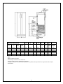
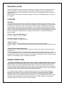
STAINLESS STEEL INDIRECT
WATER HEATERS
INSTALLATION, OPERATION and
MAINTENANCE INSTRUCTIONS
TABLE OF CONTENTS
IMPORTANT INFORMATION ……………………………………………………………………………........
GENERAL INFORMATION ……………………………………………………………………………………..
PRE-INSTALLATION ………………………………………………………………………………………......
LOCATION ……………………………………………………………….......................................................
WATER CONNECTIONS ………………………………………………………………………………….......
TEMPERATURE AND PRESSURE RELIEF VALVE ……………………………………………………….
BOILER CONNECTIONS ………………………………………………………………………………………
BOILER SYSTEM ………………………………………………………………………………………….........
ELECTRICAL CONNECTIONS ……………………………………………………………………………......
WATER TEMPERATURE ADJUSTMENT………………………………………………………………........
OPERATING INSTRUCTIONS ……………………………………………………………………………......
MAINTENANCE …………………………………………………………………………………………….......
1
2.
3.
6.
6.
6.
7.
8.
9.
9.
9.
10.
11.
IMPORTANT INFORMATION
The equipment must be installed in accordance with those installation regulations required in the area
where the installation is to be made. These regulations must be carefully followed in all cases. Authorities
having jurisdiction shall be consulted before installations are made. All wiring on water heaters installed in
the USA must be in accordance with the National Electrical Code and/or local regulations; or in Canada,
installed in accordance with the Canadian Electrical Code and/or local regulations.
The following terms are used throughout this manual to bring attention to the presence of hazards of
various risk levels, or to important information concerning product life.
DANGER
Indicates an imminently hazardous situation, which, if not avoided, will result in death, serious injury, or
substantial property damage.
CAUTION
Indicates a potentially hazardous situation, which, if not avoided, could result in death, serious injury, or
substantial property damage.
WARNING
Indicates a potentially hazardous situation, which, if not avoided, may result in moderate, or minor injury
or property damage.
NOTICE
Indicates special instructions on installation, operation or maintenance, which are important but not
related to personal injury hazards.
2
GENERAL INFORMATION
For your family’s comfort, safety, and convenience, we recommend this water heater be installed
and serviced by a plumbing professional.
WARNING
To avoid damage or injury, there must be no materials stored against the indirect water heater and proper
care shall be taken to avoid unnecessary contact (especially by children) with the indirect water heater.
Do not store or use gasoline or other flammable liquids in the vicinity of this water heater or any other
appliance.
DANGER
DO NOT store or use gasoline or other flammable, combustible, or corrosive vapors and/or liquids in the
vicinity of this or any other appliance.
IF YOU SMELL GAS:
DO NOT try to light any appliance.
DO NOT touch any electric switch; do not use any telephone in your building.
Immediately call your gas supplier from a telephone in another building. Follow the gas supplier’s
instructions.
If you cannot reach your gas supplier, call the fire department.
DO NOT OPERATE THE APPLIANCE UNTIL THE LEAKAGE IS CORRECTED!
Liquefied petroleum gas/propane gas is heavier than air and will remain at floor level if there is a leak.
Basements, crawl spaces, closets, and areas below ground level will serve as pockets for accumulation
of leaking gas.
This water heater is supplied with an adjustable thermostat to control water temperature. Hot water
temperatures required for automatic dishwasher and laundry use can cause scald burns resulting in
serious personal injury and/or death. The temperature at which injury occurs varies with the person’s age
and the time of exposure. The slower response time of disabled persons increases the hazards to them.
NEVER allow small children to use a hot water tap or to draw their own bath water. NEVER leave a child
or disabled person unattended in a bathtub or shower.
WARNING
Installation is not complete unless a pressure and temperature relief valve is installed into the side of the
water heater. This water heater contains very hot water under high pressure. Do not unscrew any pipe
fittings or attempt to disconnect any components of this water heater without positively assuring the water
is cool and has no pressure. Always wear protective clothing and equipment when installing, starting up,
or servicing this water heater to prevent scald injuries. Do not rely on the pressure and temperature
gauges to determine the temperature and pressure of the water heater. This water heater contains
components that become very hot. Do not touch any components unless they are cool. Improper
installation, adjustments, alteration, service or maintenance can cause property damage, personal injury
or loss of life. Failure to follow all instructions in the proper order can cause personal injury or death.
Read and understand all instructions, including all those contained in component manufacturer’s
manuals, which are provided with the appliance before installing, starting-up, operating, maintaining, or
servicing this appliance. Keep this manual and literature in legible condition and posted near the
appliance for reference by owner and service technician. This water heater requires regular maintenance
and service to operate safely. Follow the instructions contained in this manual. Installation, maintenance,
and service must be performed only by an experienced, skilled, and knowledgeable installer or service
agency.
3
WARNING
It is the responsibility of the installing contractor to see that all controls are correctly installed and are
operating properly when the installation is complete.
DO NOT operate the water heater with jumped out or absent controls or safety devices.
DO NOT tamper with or alter the water heater and/ or controls.
DO NOT operate the water heater if any external part has been under water. Immediately call a qualified
service technician to inspect the appliance and to replace any part of the control system that was under
water.
DO NOT install this water heater on carpeting. This water heater is suitable for installation on combustible
flooring.
DO NOT operate this water heater without first being certain it is filled with water.
Flammable items, pressurized containers, or any other potential fire hazardous articles must never be
placed on or adjacent to the heater. Containers of flammable gases should not be stored or used in the
same room with this water heater. Hydrogen gas can be produced in an operating water heater that has
not had water drawn from the tank for a long period of time (generally two weeks or more). Hydrogen gas
is extremely flammable. To prevent the possibility of injury under these conditions, we recommend that
the water faucet be opened for several minutes at the kitchen sink before you use any electrical appliance
that is connected to the hot water system. If hydrogen is present, there will be unusual sounds such as air
escaping through the pipes as hot water begins to flow. Do not smoke or have open flame near the faucet
at the time it is open.
CAUTION
The maximum boiler water supply temperature to the indirect heat exchanger must not exceed 200°F
(93°C).
NOTICE
Insulation blankets are not required for this water heater. This water heater meets or exceeds the
ASHRAE/IES 90.1b standards with respect to insulation and standby loss requirements.
NOTICE
The maximum heat transfer through the coil (heat input) of the water heater at 200°F (93°C) boiler water
supply temperature and 210°F potable water temperature is 94,000 Btu/hr. Potable water temperature is
limited to below 210°F and nominal water containing capacity is less than 120 gallons for all indirect
models. Accordingly, per Part HLW-101.2, Section IV of the ASME Boiler and Pressure Vessel Code, all
indirect products are therefore exempted from compliance with the code.
4
Stainless Steel Indirect
A
B
D
E
F
G
H
HEX
Outlet
Cold
Water
Inlet
Shipping
Weight
(lbs)
Model
Number
Gallon
Capacity
1st
Hour
Rating
@140°F
Height
Diameter
T&P
Return
HEX
Inlet
SSS030
32
142
189
37 1/2
23 1/4
27 3/4
22 3/4
19
12 1/4
2 3/4
110
SSS040
42
150
195
47 1/4
23 1/4
41
24 1/2
20 1/2
12 1/4
2 3/4
135
SSS060
60
273
360
63
23 1/4
56 3/4
31
27
12 1/4
2 3/4
155
SSS085
90
501
667
66 1/4
27 1/4
59 1/4
39 3/4
36 1/2
13 1/2
3 1/2
245
SSS120
119
529
695
82 1/4
27 1/4
75
39 3/4
36 1/2
13 1/2
3 1/2
285
1st
Hour
Rating
@115°F
Notes:
Water connections are 1" NPT
Heat Exchanger connections are 1" female NPT
Performance data is based on manufacturer's test results.
All ratings are based on 180°F boiler water temperature, 50°F potable water temperature and an approximate boiler output of
220,000 Btu/Hr.
5
PRE-INSTALLATION
INSPECT SHIPMENT carefully for any signs of damage. If damage is noted, do not install the product.
Contact the shipper or manufacturer listed on rating plate. All equipment is carefully manufactured,
inspected, and packed. Our responsibility ceases upon delivery of the packaged heater to the carrier in
good condition.
NOTE: Any claims for damage or shortage in shipment must be filed immediately against the carrier by
the consignee.
LOCATION
CAUTION
This water heater must be located in an area where leakage of the tank, water line connections, or the
temperature and pressure relief valve will not result in damage to the area adjacent to the water heater or
to lower floors of the structure. When such locations cannot be avoided, a suitable drain pan must be
installed under the water heater. The drain pan depth must be suitable for draining and collecting water,
and have a minimum length and width of at least four (4) inches measured from the jacket of the water
heater. The drain pan, as described above, can be purchased from your plumbing professional. The drain
pan must be piped to an adequate drain. The piping must be at least ¾” in diameter and pitched for
proper drainage.
Clearance from Combustible Materials
0" –Top, 0" –Sides, 0" –Front, 0" -Rear
Recommended Service Clearances
12" –Top, 4" –Sides, 16" –Front, 0" -Rear
Appliance Location
1. Boiler Location – Locate the Indirect Water Heater as close to the boiler as practical.
2. Fixture Locations – For fastest delivery of hot water, place the Indirect Water Heater close to points of
use.
Additional Recommended Components
1. Shut-off Valves – Allows isolation of water heater from domestic water system and/or boiler system
during service.
2. Unions – Allows water heater movement during service if adequate clearance cannot be provided.
3. Thermal Expansion Tank – If the water heater is installed in a closed water supply system, such as one
having a back-flow preventor in the cold water line, provide thermal expansion control. Contact the water
supplier or local plumbing inspector for additional information.
WATER CONNECTIONS
1. BEFORE PROCEEDING WITH THE INSTALLATION, CLOSE THE MAIN WATER SUPPLY VALVE.
After shutting off the main water supply, open a faucet to relieve the water line pressure to prevent any
water from leaking out of the pipes while making the water connections to the water heater. After the
pressure has been relieved, close the faucet. The COLD water inlet and HOT water outlet are identified
on the water heater. Make the proper plumbing connections between the water heater and the plumbing
system to the house. Install a shut-off valve in the cold water supply line.
2. If this water heater is installed in a closed water supply system, such as one having a back-flow
preventor in the cold water supply, provisions must be made to control thermal expansion. DO NOT
operate this water heater in a closed system without provisions for controlling thermal expansion.
Warranties do not cover damages from thermal expansions such as pressure bulges and/or deformities.
A properly sized expansion tank will alleviate most problems. Your water supplier or local plumbing
inspector should be contacted on how to control this situation.
6
3. After installation of the water lines, open the main water supply valve and fill the water heater. While
the water heater is filling, open several hot water faucets to allow air to escape from the water system.
When steady streams of water flow through the faucets, close them and check all water connections for
possible leaks.
4. NEVER OPERATE THE WATER HEATER WITHOUT FIRST BEING CERTAIN THAT IT IS FILLED
WITH WATER.
TEMPERATURE AND PRESSURE RELIEF VALVE
WARNING
Keep clear of the combination temperature and pressure relief valve discharge line outlet. The discharge
may be hot enough to cause scald injury. The water is under pressure and may splash. For protection
against excessive temperatures and pressure, install temperature and pressure protective equipment
required by local codes, but not less than a combination temperature and pressure relief valve certified by
a nationally recognized testing laboratory that maintains periodic inspection of production of listed
equipment or materials as meeting the requirements of the Standard for Relief Valves and Automatic Gas
Shutoff Devices for Hot Water Supply Systems, ANSI Z21.22 and the Standard CAN1-4.4 Temperature,
Pressure, Temperature and Pressure Relief Valves and Vacuum Relief Valves. The combination
temperature and pressure relief valve must be marked with a maximum set pressure not to exceed the
maximum working pressure of the water heater. The combination temperature and pressure relief valve
must also have an hourly rated temperature steam BTU discharge capacity not less than the hourly rating
of the water heater. The supplied combination temperature and pressure relief valve, when properly
installed and unrestricted, will discharge the maximum input produced by a 200°F (93°C) boiler supply
temperature. A lower boiler supply temperature will reduce the input required to be discharged in the
event of excessive potable water temperatures. Install the combination temperature and pressure relief
valve into the opening provided and marked for this purpose on the water heater. Some models may
already be equipped or supplied with a temperature and pressure relief valve. Verify that the combination
temperature and pressure relief valve complies with local codes. If the temperature and pressure relief
valve does not comply with local codes, replace it with one that does.
WARNING
Install a discharge line so that water discharged from the temperature and pressure relief valve will exit
within six (6) inches above, or any distance below, the structural floor and cannot contact any live
electrical part. The discharge line is to be installed to allow for complete drainage of both the temperature
and pressure relief valve and the discharge line. The discharge opening must not be subjected to
blockage or freezing. DO NOT thread, plug, or cap the discharge line. It is recommended that a minimum
clearance of four (4) inches be provided on the side of the water heater for servicing and maintenance of
the combination temperature and pressure relief valve. Do not place a valve between the combination
temperature and pressure relief valve and the tank!
7
BOILER CONNECTIONS
The Indirect connection labeled “BOILER WATER OUT” should be piped to the boiler water return piping
as close to the boiler as possible and after any flow control or check valves in the space heating return
piping. The use of a union and a shut-off valve is recommended. The use of a flow control or check valve
is required to prevent back flow through the water heater during operation of the space heating system.
Pipe and fittings between the boiler and Indirect should be ¾” diameter or larger.
The Indirect connection labeled “BOILER WATER IN” should be piped to the boiler water supply piping.
Mount the circulator making sure the flow arrow points toward the water heater. The use of Shut-off
valves and unions are recommended for future service convenience. The use of an air separator and vent
is recommended to eliminate air in the system. Pipe and fittings between the boiler and Single-wall
Indirect must be ¾” diameter or larger.
Figure 1. – System with Zone Valves
Figure 2. – System with Circulators
8
BOILER SYSTEM
1. On new boiler installations, do not purge the boiler or space heating system through the water heater.
During any boiler or space heating system flushing, cleaning, or purging, the water heater should be
isolated to avoid possible attack on the coil by chemical additives.
2. Purge air from boiler/water heater piping.
3. Check system for leaks. Repair as necessary.
ELECTRICAL CONNECTIONS
Install electric wiring in accordance with National Electric Code or the Canadian Electrical Code and local
regulations. See the boiler’s installation manual for wiring diagrams. The Indirect is equipped with an
adjustable temperature control. Once electrical connections are complete, secure the control cover back
in place. AT NO TIME SHOULD WATER HEATER OPERATION TAKE PLACE WITHOUT THE COVER
ON THE CONTROL.
INSTALLING THEROMSTAT WIRING
1. Remove (4) screws from cover to remove front control panel.
2. Feed 24 volt wire from boiler control through the opening on the top pan labeled
“thermostat connection. Install female ¼” connectors on the wiring and connect to
the (2) two ¼” spade terminals on the thermostat.
3. Make sure all wiring is safely inside the junction box and reinstall the front
control panel cover.
Figure 3.
DANGER
Positively assure all electrical connections are unpowered before attempting installation or service of
electrical components or connections of the water heater or building. Lock out all electrical boxes with
padlock once power is turned off.
WARNING
When installed, the water heater must be electrically grounded in accordance with local codes or, in the
absence of local codes, with the National Electrical Code, ANSI/NFPA 70, and /or the CSA C22.1 Electric
Code. Failure to properly wire electrical connections to the water heater may result in serious physical
harm. Electrical power may be from more than one source. Make sure all power is off before attempting
any electrical work.
WATER TEMPERATURE ADJUSTMENT
WARNING - SCALDING
This water heater can deliver scalding temperature water at any faucet in the system. Be careful
whenever using hot water to avoid scalding injury. By setting the thermostat on this water heater
to obtain an increased water temperature, you may create the potential for scald injury. To protect
against injury, you should install an ASSE approved mixing valve (a device to limit the
temperature of water to protect against scald injury via mixing hot and cold water supply) in the
water system. This valve will reduce point of discharge temperature in branch supply lines. Such
valves are available from the manufacturer of this water heater or a local plumbing supplier.
Please consult with a plumbing professional.
9
1. The thermostat controls the maximum water temperature in the tank. The differential is a fixed 5°F with
a 170°F maximum setting. See Approximate Time/Temperature Relationship guide to determine the
safest water temperature for your applications.
2. For the most energy efficient operation, adjust the thermostat for the minimum water temperature
necessary to meet domestic hot water needs. IT IS NOT NECESSARY TO REMOVE THE COVER TO
ADJUST THE TEMPERATURE SETTING. THE THERMOSTAT COVER SHOULD NEVER BE
REMOVED WITHOUT ELECTRICITY BEING FIRST DISCONNECTED.
3. After the water heater completes a heat-up cycle, check the water temperature at a faucet. Allow
enough water to flow to ensure that the water temperature reflects the tank temperature. Adjust the water
heater’s temperature setting as necessary.
a. Adjusting to a lower temperature setting will not immediately affect water temperature. Draw sufficient
water or allow the water heater to sit until a heat-up cycle is initiated. Repeat step 3.
b. Adjusting to a higher temperature may not immediately affect water temperature. If a heat up cycle
begins, return to step 3. If a heat-up cycle does not begin, draw sufficient water or allow the water heater
to sit until a heat-up cycle is initiated. Repeat step 3.
APPROXIMATE TIME/TEMPERATURE RELATIONSHIPS IN SCALDS
120°F More than 5 minutes
125°F 1 ½ to 2 minutes
130°F About 30 seconds
135°F About 10 seconds
140°F Less than 5 seconds
145°F Less than 3 seconds
150°F About 1 ½ seconds
155°F About 1 second
CAUTION
Before manually operating the valve, make sure that a drain line has been attached to the valve to
direct the discharge to an open drain. Failure to take this precaution could mean contact with
extremely hot water discharging from the valve during this checking operation.
OPERATING INSTRUCTIONS
BOILER SYSTEM START-UP
Follow boiler installation instructions to place boiler in operation.
SEQUENCE OF OPERATIONS
1. Thermostat senses stored water temperature below desired setting.
a. Normally open contacts close to interrupt space heating.
2. Thermostat senses stored water temperature at desired setting.
a. Normally open contacts open, returning boiler control to space heating.
10
MAINTENANCE
The Indirect Water Heater is intended to provide a service life of many years. Components that require
service, however, may be subject to failure. Failure to use the correct procedures or parts in these
circumstances may make the water heater unsafe. The owner should arrange to have the following
inspections and simple maintenance procedure performed by qualified service personnel at the
frequencies suggested.
1. Boiler and Domestic Water Piping (Annual) – Check all piping for signs of leakage at joints, unions,
and shut-off valves. Repair as needed.
2. Temperature-Pressure Relief Valve (Annual) - The temperature-pressure relief valve should be
checked to ensure that it is in operating condition. To check the relief valve, lift the lever at the end of the
valve several times. The valve should seat properly and operate freely. If water does not flow, remove
and inspect for obstructions or corrosion. Replace with a new valve of the recommended size as
necessary. Do not attempt to repair the valve, as this could result in improper operation and a tank
explosion. In areas with poor water conditions, it may be necessary to inspect the temperature-pressure
relief valve more often than once a year. If the temperature–pressure relief valve on the heater
discharges periodically or continuously, it may be due to thermal expansion of water in a closed water
supply system, or it may be due to a faulty relief valve. Thermal expansion is the normal response of
water when it is heated. In a closed system, thermal expansion will cause the system pressure to build
until the relief valve actuation pressure is equaled. Then the relief valve will open, allowing some water to
escape, slightly lowering the pressure. Contact your water supplier or local plumbing inspector on how to
control this situation.
ABOVE ALL, DO NOT PLUG THE TEMPERATURE AND PRESSURE RELIEF VALVE. THIS IS NOT A
SOLUTION AND CAN CREATE A HAZARDOUS SITUATION.
3. Sediment (Annual, but harsh water quality may dictate more frequent service) - Depending on
water conditions, a varying amount of sediment may collect in the tank. Levels requiring service are
indicated by a small temperature difference in the supply and return lines (See also “Scale” below).
Repeated flushing usually clears such material. As a preventive measure, water should be drawn from
the tank at the drain valve until it runs clear.
4. Scale (Annual) - Hard water may cause scale to build-up on the outside of the heat exchanger coil. A
water softener will prevent this problem (See also “Sediment” above). Symptoms would include reduced
recovery capacity or reduced temperature differential between boiler supply and return lines. Repeated
flushing should resolve the problem.
11
NOTES:
300 Maddox Simpson Parkway
Lebanon, TN 37090
615-889-8900
www.Lochinvar.com
12