1
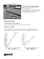
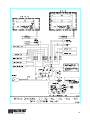
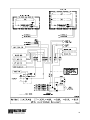
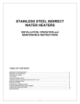
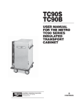
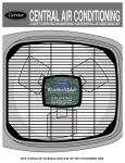
GT-30 & GT-40
Installation & Operations Manual
J-Version
Master-Bilt Products
908 Highway 15 North
New Albany, MS 38652
Phone: (800) 684-8988
PN 029-90000
Rev 03/12/07 LN
2
TABLE OF CONTENTS
INTRODUCTION..................................................................................................................................................4
STORE CONDITIONS .........................................................................................................................................4
WARNING LABELS AND SAFETY INSTRUCTIONS........................................................................................5
PRE-INSTALLATION INSTRUCTIONS ..............................................................................................................6
Inspection for Shipping Damage.............................................................................................................6
INSTALLATION INSTRUCTIONS.......................................................................................................................6
General Instructions ................................................................................................................................6
Electrical..................................................................................................................................................6
MECHANICAL .....................................................................................................................................................7
Leveling Cabinet .....................................................................................................................................7
Grille Removal and Compressor Check..................................................................................................7
START UP ...........................................................................................................................................................7
Fan Operation and Vibration; Voltage Check .........................................................................................7
Thermostat Check...................................................................................................................................7
Defrost and Temperature Control ...........................................................................................................8
AUTOMATIC EXPANSION VALVE ....................................................................................................................9
REFRIGERATION SYSTEM AND OPERATION ................................................................................................9
CLEANING...........................................................................................................................................................9
EXTERIOR PARTS NOMENCLATURE............................................................................................................10
Glass Lid and Top Deck Removal ........................................................................................................10
Drain Pan and Light Shield Removal ....................................................................................................11
SERVICE INSTRUCTIONS ...............................................................................................................................11
Operation Conditions and Pressures ....................................................................................................11
Trouble Shooting Guide ........................................................................................................................12
MASTER-BILT PART NUMBERS.....................................................................................................................13
ACCESSORIES .................................................................................................................................................14
SALE AND DISPOSAL .....................................................................................................................................14
WIRING DIAGRAMS GT ............................................................................................................................. 15-16
3
INTRODUCTION
Thank you for purchasing a Master-Bilt cabinet. This manual contains important instructions for installing,
using and servicing a Master-Bilt GT case. A parts list is included in with this manual. Read all these
documents carefully before installing or servicing your equipment.
STORE CONDITIONS
The Master-Bilt GT cases are designed to operate in the controlled environment of an air-conditioned store.
The store temperature should be at or below 75°F and a relative humidity of 55% or less. At higher
temperature or humidity conditions, the performance of these cases may be affected and the capacity
diminished. It is not uncommon in a newly constructed store for the temperature and humidity to be above
design conditions. These excessive conditions may produce sweating in the case until the store is operational
and the ambient environment is more desirable.
The Master-Bilt GT should not be positioned where it is directly exposed to rays of sun or near a direct source
of radiant heat or airflow. This will adversely affect the case and will result in poor performance.
The Master-Bilt GT cabinets may be placed directly against the wall. This is due to the cabinet’s condenser
cooling air entering and discharging through the front grille.
NOTICE
Read this manual before installing your cabinet. Keep the manual and refer to it before
doing any service on the equipment. Failure to do so could result in personal injury or damage to the
cabinet.
DANGER
Improper or faulty hook-up of electrical components of the refrigeration units can result in
severe injury or death.
All electrical wiring hook-ups must be done in accordance with all applicable local, regional or national
standards.
NOTICE
Installation and service of the refrigeration and electrical components of the cabinet must
be performed by a refrigeration mechanic and/or a licensed electrician.
The portions of this manual covering refrigeration and electrical components contain technical instructions
intended only for persons qualified to perform refrigeration and electrical work. This manual cannot cover
every installation, use or service situation. If you need additional information have the serial number at hand
and call or write us:
Customer Service Department
Master-Bilt Products
Highway 15 North
New Albany, MS 38652
Phone (800) 684-8988
Fax (800) 684-8988
4
WARNING LABELS AND SAFETY INSTRUCTIONS
This symbol is the safety-alert symbol. When you see this symbol on your cabinet or in
this manual, be alert to the potential for personal injury or damage to your equipment.
Be sure you understand all safety messages and always follow recommended precautions and safe operating
practices.
NOTICE TO EMPLOYERS
You must make sure that everyone who installs, uses or services your cabinet is thoroughly familiar
with all safety information and procedures.
Important safety information is presented in this section and throughout this section and throughout the
manual. The following signal words are used in the warnings and safety messages:
DANGER:
Severe injury or death will occur if you ignore the message.
WARNING: Severe injury or death can occur if you ignore the message.
CAUTION: Minor injury or damage to your cabinet can occur if you ignore the message.
NOTICE:
This is important installation, operation or service information. If you ignore the
message, you may damage your cabinet.
The warning and safety labels shown throughout this manual are placed on your Master-Bilt Products
cabinet at the factory. Follow all warning label instructions. If any warning or safety labels become
lost or damaged, call your customer service department at (800) 684-8988 for replacements.
CAUTION!
GROUND REQUIRED
FOR SAFE OPERATION
This label is located on top of the electrical control
label and on the wiring channel.
This label is attached to the cabinet power cord
on models with a power cord.
5
PRE-INSTALLATION INSTRUCTIONS
INSPECTION FOR SHIPPING DAMAGE
You are responsible for filing all freight claims with the delivering truck line. Inspect all cartons and crates for
damage as soon as they arrive. If damage is noted to shipping crates or cartons or if a shortage is found, note
this on the bill of lading (all copies) prior to signing.
If damage is discovered when the cabinet is uncrated, immediately call the delivering truck line and follow up
the call with a written report indicating concealed damage to your shipment. Ask for an immediate inspection
of your concealed damage item. Crating material must be retained to show the inspector from the truck line.
INSTALLATION INSTRUCTIONS
GENERAL INSTRUCTIONS
1. Be sure the equipment is properly installed by competent service people.
2. Keep the equipment clean and sanitary so it will meet your local sanitation codes.
3. Rotate your stock so that older stock does not accumulate. This is especially important for ice cream. A
"First-In, First-Out" rotation practice will keep the products in good sellable condition.
4. Do not place product in the case when it is soft or partially thawed. Also, product should not be put in the
case for at least 6 hours after it is started.
5. Stock cases as quickly as possible, exposing only small quantities to store temperatures for short periods
of time.
6. When replacing burned out fluorescent tubes, be sure that the electrical power to the lighting circuit is
turned off.
NOTICE TO STORE OWNERS / MANAGERS
Moisture or liquid around or under the cabinet is a potential slip/fall hazard for persons walking by or working in
the general area of the cabinet. Any cabinet malfunction or housekeeping problem that creates a slip/fall
hazard around or under the cabinet should be corrected immediately.
If moisture or liquid is observed around or under a Master-Bilt cabinet, an immediate investigation should be
made by qualified personnel to determine the source of the moisture or liquid. The investigation should
determine if the cabinet is malfunctioning or if there is a drainpipe leaking.
ELECTRICAL
WARNING
Before servicing electrical components in the case, make sure all power to case is off. Always use a
qualified technician.
ELECTRICAL INFROMATION AND GROUNDING
A separate circuit for each cabinet is recommended to avoid the possibility of other appliances on a circuit to one
of these cabinets overloading that circuit and causing malfunction. The electrical service should be grounded
upon installation.
6
MECHANICAL
Leveling Cabinet
Level the cabinet so as to insure proper drainage of the drain pan and proper operation of the lids and
refrigeration system. The GT cabinet condenser has cooling air entering and discharging through the front
grille. This allows the cabinet to be placed against a wall or solid object without blocking the flow of condenser
air.
To comply with Sanitation requirements, the cabinet must be mounted on legs (6” high minimum) or the base
must be sealed to the floor using N.S.F. listed RTV silicone sealant. Minimum clearance as follows: 0” rear
and side, top and front are open required for compliance.
Grille Removal And Compressor Check
Remove grille and check refrigeration lines to see that they are free (not touching each other or compressor).
Spin condenser fan blade to see that it is free.
Check that all service valves (2) are open. The springs are secured for shipping by either tightening
bolts or shipping strap. Remove the strap or loosen the hold-down bolts so that the compressor floats
freely.
Semi-Hermetic Compressor
STARTUP
FAN OPERATION AND VIBRATION; VOLTAGE CHECK
Uncoil the lead cord and pass it through the hole provided in the cover. While the cabinet is in operation,
check the voltage draw and the amperage draw versus this rating on the nameplate. Check for fan noise and
vibration, while the fan is running. Voltage should be checked at the compressor terminals while the
compressor is initially starting. The unit is designed to operate at +/- 10% of 115 volts, 60 cycles, and single
phase. This means that the voltage should be between 103 and 126.5 volts.
THEROMSTAT CHECK
After the cabinet has pulled down in temperature to approximately 0°F at load line, check the thermostatic
control by turning it to its warmest position. This should shut the compressor off. Also check that the main
double-pole double throw toggle switch turns the refrigeration system and cabinet lights. A separate circuit for
each cabinet is recommended to avoid the possibility of other appliances on a circuit overloading the circuit
and causing a malfunction. Make sure that the electrical service is grounded upon installation.
7
DEFROST AND TEMPERATURE CONTROL
SETTINGS
The GT cabinet has a temperature control that is adjustable from #1
(warmest setting) to #9 (coldest setting). Turn the control knob in
line with the punch mark to the desired setting. The temperature
control is located near the condensing unit at the bottom of the
cabinet.
Punch Mark
The unit defrost is controlled by a timer in the
control box. After removing the condenser grille,
the control box will slide out until the defrost timer
is visible. The factory set defrost is two times in 24
hours with a maximum timed interval of 30
minutes. The unit contains a defrost termination
sensor so in actual use the defrost time will be less
than 30 minutes in most cases. The timer can be
converted to operate for a timed defrosts
termination by disconnecting the blue/white from
the X terminal. NOTE: When disconnected, it is
recommended that the terminal be cut off of the
blue/white wire and the wire end be capped with a
wire nut.
30 minutes
Pointer
The defrost time is set by switching a white key from the
30 Minutes
center to the outside edge of the dial. Each key is 15
minutes so two successive keys must be switched outward for a 30 minute maximum time defrost. If it is
noted that more defrost time is needed, then switch outward the third successive key for a 45-minute
maximum timed defrost. If another defrost in 24 hours is needed then more keys can be switched outward as
needed. If possible, try to keep defrosts evenly spaced in a 24 hour period.
The current time can be set by turning the outer dial in the direction of the arrow until the correct clock time is
shown and the small arrow aligns with either the AM or PM scale.
NOTE: The cabinet serial number for the GT is on the data plate located on the end opposite the
condensing unit.
8
AUTOMATIC EXPANSION VALUE GT SERIES CABINETS
After the cabinet has been in operation for a short time the high pressure or discharge pressure of the
o
refrigeration system should be 250 pisg to 270 pisg in a 75 F ambient room. The suction pressure at the
compressor should be approximately 7 to 9 pisg *** . The cabinet does not have to be at operation
temperatures for the pressures to stabilize. The automatic expansion valves are basically preset and should
not need any adjustment for proper operation. If the system pressures are not correct and the valve does
need adjusting be aware that IN THE WORST CASE ONLY A VERY SMALL ADJUSTMENT MAY BE
REQUIRED. To increase the valve outlet pressure and thereby increase the suction pressure the adjusting
screw is turned in a clockwise direction as the valve is viewed with the adjusting screw pointed up. Be sure to
replace the red plastic cap covering the valve adjustment screw. After the pressure is set it SHOULD NOT
TEND TO CHANGE after additional run time or as the cabinet temperature changes. The sight glass, if install,
may not appear to be completely full. This is a normal condition. DO NOT INCREASE the refrigerant charge
quantity above the listed charge because the sight glass does not show full.
*** Units used for boxed candy display should have the expansion valve adjusted to deliver 12
to 14psig at compressor suction port, this pressure is not suitable for ice-cream.
REFRIGERATION SYSTEM AND OPERATION
The cabinet utilizes a Copeland Copelametric compressor and operates with refrigerant 404A. Cabinet
operates on 115/60/1 power. The cabinet has a bare tube type condenser, which virtually eliminates the
possibility of condenser blockage by dust and dirt.
The cabinet operates with a specific charge of refrigerant 404A. The amount of the charge of refrigerant is
listed on the cabinet nameplate in ounces. These systems use an automatic expansion valve to meter
refrigerant to the evaporator. They include automatic electric defrost systems which are time initiated (by the
time clock) and terminated by a defrost termination thermostat which is mounted on a coil supporting bracket
in the gravity coil section directly beneath the top of the cabinet. This defrost termination overrides the time
clock and turns the compressor back on line when the gravity coil is defrosted. This is the point at which the
coil has reached sufficient temperature to insure complete defrost. If the defrost termination control should fail
to operate, the time clock will automatically turn off defrost and again turn on the compressor after the 34
minute (or the time interval you selected) interval set on the time clock. If the time clock fails to turn the
heaters off, a final back-up safety thermostat will shut off the heaters when gravity coil temperature reaches
o
+80 F.
Cabinet has a refrigeration system known as automatic defrost gravity coil with cold wall construction. This
means the inner liner of the cabinet below the load level line is refrigerated by gravity flow of air from a fin and
tube coil, as well as copper refrigerant lines attached to the back of the inner liner tank on all sides and the
bottom.
CLEANING
WARNING: DO NOT REMOVE FROST WITH A KNIFE, PICK, OR SHARP OBJECTS. DO NOT USE
ABRASIVE CLEANERS OR CAUSTIC CLEANERS OR SCOURING PADS
Every 30 to 60 days (depending on frost accumulation), the cabinet should be emptied, warmed up, and wiped
down using a solution of 1 teaspoon of baking soda with 1 quart of water. This solution will help eliminate
odors. Do not use strong soaps or detergents as they leave odors that can contaminate your product. The
GT line cabinets are equipped with a floor drain that exits out the lower rear of the cabinet. This exit has a
convenient garden hose fitting.
If it is not convenient to turn the power off the cabinet, lay a piece of plastic sheeting on the floor of the cabinet
and scrape the frost off walls using a plastic scraper. Do not use metal scrapers. This will damage the interior
paint of the cabinet.
9
EXTERIOR PARTS NOMENCLATURE
C
B
A
D
G
H
E
I
F
J
A.
B.
C.
D.
E.
F.
K
TOP DECK
CENTER TRACK
TRIM MOLDING
GLASS RAIL
GLASS LID
FRONT GLASS
L
G.
H.
I.
J.
K.
L.
VERTICAL TRIM
FRONT PANEL
LOWER BUMPER
UPPER BUMPER
ACCESS PANEL
UNIT GRILLE
Glass Lid and Top Deck Removal
To remove the glass lid, start in the closed
position and lift up on the front extrusion. Pull the
glass lid towards you to remove it from the track.
Reverse procedure to reinstall.
Top Deck
Price Tag
To remove the top deck, slide (remove) insert strip
from price tag moulding. Remove screws, which
are now exposed to remove the price tag
moulding. Remove screws on sides of the
cabinet, which also attach the top deck. Reverse
procedure to reinstall.
Glass Lid
10
Drain Pan and Light Shield Removal
Light Shield
To remove the drain pan, remove screws along the front
face of the drain pan. Lift the rear of the pan up and out
of the drain trough. Slide pan towards you and out.
Reverse procedure to install.
To remove the light shield, remove screws along the front
face of the light shield. Pull the light shield towards you
and out. Reverse procedure to reinstall.
Drain Pan
SERVICE INSTRUCTIONS
OPERATION CONDITIONS AND PRESSURES
o
With room ambient temperature of +80 F and cold cabinet (unit cycling on control):
Suction pressure – 5 to 9 psig.
Head pressure – 210 to 260 psig.
Typical operating pressures for a properly charged unit operating at 0°F or lower box temperature, check
pressures immediately before normal off cycle expect a tolerance of ± 5 psig high side, and ±1 psig low side.
11
TROUBLE SHOOTING GUIDE
1.
High head pressure and high back pressure:
A.
B.
C.
D.
2.
Low back pressure and low head pressure:
A.
B.
C.
3.
Expansion valve restriction.
Refrigerant undercharged.
Leak in system.
Pressures normal – cabinet warm:
A.
B.
4.
Condenser coil clogged or restricted.
Condenser fan motor defective.
Air in the system.
Refrigeration overcharge.
Refrigerant undercharged.
Control set too warm.
Compressor starts and runs – but cycles on overload:
A.
B.
C.
Low voltage.
Overload protector defective.
High head pressure (see#1).
5.
Compressor will not start – hums, but cycles on overload:
6.
A.
Low voltage.
B.
Relay defective.
C.
Overload defective.
D.
High head pressure (see #1).
Cabinet sweating:
A.
B.
7.
High ambient humidity.
Defective condensate heater.
Cabinet not cycling – coil blocked with frost:
A.
B.
C.
D.
E.
F.
Defective temperature controller.
Refrigerant overcharged.
Location too hot.
Condenser clogged.
Condenser fan motor defective.
Defrost heater not operating.
8.
Gravity coil will not defrost (coil loaded with ice or frost)
A.
Solenoid in timer sticking closed, preventing unit from going defrost.
B.
Defrost termination thermostat is defective.
C.
Safety thermostat is defective.
D.
Timer defrost is not set at minimum 34 minutes
E.
Defective defrost coil heater.
9.
Defrost cycle too long.
A.
Defective time clock solenoid.
B.
Defective defrost end thermostat and/or defective safety thermostat.
12
10.
Special service situations.
If moisture or liquid is observed around or under a Master-Bilt cabinet, an immediate investigation
should be made by qualified personnel to determine the source of moisture or liquid. The investigation
made should determine if the cabinet is malfunctioning or if there is a simple housekeeping problem.
Moisture or liquid around or under a cabinet is a potential slip/fall hazard for persons walking by or
working in the general area of the cabinet.
Any cabinet malfunction or housekeeping problem that creates a slip/fall hazard around or under a
cabinet should be corrected immediately.
MASTER-BILT PART NUMBERS
The table below gives Master-Bilt part numbers. Use this chart when ordering replacement parts for your GT cases.
Description
Aluminum Extrusions: Bumper
Upper Hand Rail
Lid Handle
Trim, L.H. And Front
Trim, R.H. and Front
Coil Defrost Heater
Compressor
Condenser Coil
Condenser Fan Blade
Condenser Fan Motor
Condenser Fan Motor Bracket
Defrost Heater Clip
Defrost Termination Control
Drain Trough Heater
Drier
Evaporator Coil
Expansion Valve
Fluorescent Lamp
Front Glass Heater
Front Glass Seal
Glass
Glass Lid
Heater Safety Control
Lamp Ballast
Lid Center Track
Light Shield Heater
Mullion Heater
Plastic Trim, RH Side Panel
Plastic Trim, LH Side Panel
Power Cord
Price Tag Extrusion, 10’
Side Panel Heater, RH
GT-30
49-01273
49-01274
49-01119
49-01138
49-01139
17-09114
03-14505
07-13239
15-13093
13-00311
13-00754
17-09128
19-01163
17-09117
09-09171
07-13101
09-09660
23-01576
17-09116
31-00859
31-01690
31-00851
19-01164
23-01693
17-09118
17-09115
29-00600
29-00601
21-00312
49-01434
17-00408
GT-40
49-01126
49-01121
49-01117
49-01138
49-01139
17-09047
03-14505
07-13239
15-13093
13-00311
13-00754
17-09128
19-01163
17-09040
09-09171
07-13079
09-09660
23-01577
17-09039
31-00859
31-01465
31-01464
19-01164
23-01693
49-01131
17-09042
17-09044
29-00600
29-00601
21-00312
49-01434
17-00408
Side Panel Heater, LH
Lamb holder Spring
Lamb holder Fixed
Temperature Control
Timer
Toggle Switch
Toggle Switch (Lights and Heaters)
17-00409
23-01698
23-01699
19-13765
19-00818
19-01090
19-00199
17-00409
23-01698
23-01699
19-13765
19-00818
19-01090
19-00199
13
ACCESSORIES
Description
Casters 3” Dia.
Load Level Shelves
Lid Locking Kits-Less Locks
Novelty Baskets (White Epoxy-Coated) 9.125” X 12” X 7.125”
Sack Rack 48” X 17.5” X 3”
Superstructures
GT-30
A029-11140 (4)
A027-18027
A027-11129
33-01405
GT-40
A029-11140 (4)
A029-18027
A029-11129
33-01405
A027-20200
A029-20200
SALE AND DISPOSAL
OWNER RESPONSIBILITY
If you sell or give away your Master-Bilt cabinet you must make sure that all safety labels and the Installation Service Manual are included with it. If you need replacement labels or manuals, Master-Bilt will provide them
free. Contact the customer service department at Master-Bilt at (800) 684-8988.
The customer service department at Master-Bilt should be contacted at the time of sale or disposal of your
cabinet so records may be kept of its new location.
If you sell or give away your Master-Bilt cabinet and you evacuate the refrigerant charge before shipment,
Master-Bilt recommends that the refrigerant charge be properly recovered in compliance with section 608 of the
Clean Air Act effective November 1995 and in accordance with all applicable local, regional, or national
standards.
14
15
16