1
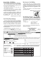
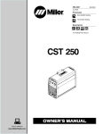
RETURN TO MAIN MENU
IM605
Square Wave TIG 175
For use with machines having Code Numbers:
July, 1997
10456
Safety Depends on You
Lincoln arc welding and cutting
equipment is designed and built
with safety in mind. However, your
overall safety can be increased by
proper installation ... and thoughtful
operation on your part. DO NOT
INSTALL, OPERATE OR REPAIR
THIS EQUIPMENT WITHOUT
READING THIS MANUAL AND
THE SAFETY PRECAUTIONS
CONTAINED
THROUGHOUT.
And, most importantly, think before
you act and be careful.
OPERATOR’S MANUAL
World's Leader in Welding and Cutting Products
Premier Manufacturer of Industrial Motors
Sales and Service through Subsidiaries and Distributors Worldwide
22801 St. Clair Ave. Cleveland, Ohio 44117-1199 U.S.A. Tel. (216) 481-8100
i
i
SAFETY
WARNING
CALIFORNIA PROPOSITION 65 WARNINGS
For Gasoline Engines: The engine exhaust from
For Diesel Engines: Diesel engine exhaust and
this product contains chemicals known to the
some of its constituents are known to the State
State of California to cause cancer, birth defects,
of California to cause cancer, birth defects, and
or other reproductive harm.
other reproductive harm.
ARC WELDING CAN BE HAZARDOUS. PROTECT YOURSELF AND OTHERS FROM POSSIBLE SERIOUS INJURY OR DEATH.
KEEP CHILDREN AWAY. PACEMAKER WEARERS SHOULD CONSULT WITH THEIR DOCTOR BEFORE OPERATING.
Read and understand the following safety highlights. For additional safety information, it is strongly recommended that you
purchase a copy of “Safety in Welding & Cutting - ANSI Standard Z49.1” from the American Welding Society, P.O. Box 351040,
Miami, Florida 33135 or CSA Standard W117.2-1974. A Free copy of “Arc Welding Safety” booklet E205 is available from the
Lincoln Electric Company, 22801 St. Clair Avenue, Cleveland, Ohio 44117-1199.
BE SURE THAT ALL INSTALLATION, OPERATION, MAINTENANCE AND REPAIR PROCEDURES ARE
PERFORMED ONLY BY QUALIFIED INDIVIDUALS.
FOR ENGINE
powered equipment.
1.h. To avoid scalding, do not remove the
radiator pressure cap when the engine is
hot.
1.a. Turn the engine off before troubleshooting and maintenance
work unless the maintenance work requires it to be running.
____________________________________________________
1.b.Operate engines in open, well-ventilated
areas or vent the engine exhaust fumes
outdoors.
____________________________________________________
1.c. Do not add the fuel near an open flame welding arc or when the engine is running. Stop
the engine and allow it to cool before refueling to prevent spilled fuel from vaporizing on
contact with hot engine parts and igniting. Do
not spill fuel when filling tank. If fuel is spilled,
wipe it up and do not start engine until fumes
have been eliminated.
____________________________________________________
1.d. Keep all equipment safety guards, covers and devices in position and in good repair.Keep hands, hair, clothing and tools
away from V-belts, gears, fans and all other moving parts
when starting, operating or repairing equipment.
____________________________________________________
1.e. In some cases it may be necessary to remove safety
guards to perform required maintenance. Remove
guards only when necessary and replace them when the
maintenance requiring their removal is complete.
Always use the greatest care when working near moving
parts.
___________________________________________________
1.f. Do not put your hands near the engine fan.
Do not attempt to override the governor or
idler by pushing on the throttle control rods
while the engine is running.
ELECTRIC AND
MAGNETIC FIELDS
may be dangerous
2.a. Electric current flowing through any conductor causes
localized Electric and Magnetic Fields (EMF). Welding
current creates EMF fields around welding cables and
welding machines
2.b. EMF fields may interfere with some pacemakers, and
welders having a pacemaker should consult their physician
before welding.
2.c. Exposure to EMF fields in welding may have other health
effects which are now not known.
2.d. All welders should use the following procedures in order to
minimize exposure to EMF fields from the welding circuit:
2.d.1. Route the electrode and work cables together - Secure
them with tape when possible.
2.d.2. Never coil the electrode lead around your body.
2.d.3. Do not place your body between the electrode and
work cables. If the electrode cable is on your right
side, the work cable should also be on your right side.
2.d.4. Connect the work cable to the workpiece as close as
possible to the area being welded.
___________________________________________________
1.g. To prevent accidentally starting gasoline engines while
turning the engine or welding generator during maintenance
work, disconnect the spark plug wires, distributor cap or
magneto wire as appropriate.
2.d.5. Do not work next to welding power source.
Mar ‘95
ii
ii
SAFETY
ELECTRIC SHOCK can kill.
ARC RAYS can burn.
3.a. The electrode and work (or ground) circuits
are electrically “hot” when the welder is on.
Do not touch these “hot” parts with your bare
skin or wet clothing. Wear dry, hole-free
gloves to insulate hands.
4.a. Use a shield with the proper filter and cover
plates to protect your eyes from sparks and
the rays of the arc when welding or observing
open arc welding. Headshield and filter lens
should conform to ANSI Z87. I standards.
3.b. Insulate yourself from work and ground using dry insulation.
Make certain the insulation is large enough to cover your full
area of physical contact with work and ground.
4.b. Use suitable clothing made from durable flame-resistant
material to protect your skin and that of your helpers from
the arc rays.
In addition to the normal safety precautions, if welding
must be performed under electrically hazardous
conditions (in damp locations or while wearing wet
clothing; on metal structures such as floors, gratings or
scaffolds; when in cramped positions such as sitting,
kneeling or lying, if there is a high risk of unavoidable or
accidental contact with the workpiece or ground) use
the following equipment:
• Semiautomatic DC Constant Voltage (Wire) Welder.
• DC Manual (Stick) Welder.
• AC Welder with Reduced Voltage Control.
4.c. Protect other nearby personnel with suitable, non-flammable
screening and/or warn them not to watch the arc nor expose
themselves to the arc rays or to hot spatter or metal.
3.c. In semiautomatic or automatic wire welding, the electrode,
electrode reel, welding head, nozzle or semiautomatic
welding gun are also electrically “hot”.
3.d. Always be sure the work cable makes a good electrical
connection with the metal being welded. The connection
should be as close as possible to the area being welded.
3.e. Ground the work or metal to be welded to a good electrical
(earth) ground.
3.f. Maintain the electrode holder, work clamp, welding cable and
welding machine in good, safe operating condition. Replace
damaged insulation.
3.g. Never dip the electrode in water for cooling.
3.h. Never simultaneously touch electrically “hot” parts of
electrode holders connected to two welders because voltage
between the two can be the total of the open circuit voltage
of both welders.
3.i. When working above floor level, use a safety belt to protect
yourself from a fall should you get a shock.
3.j. Also see Items 6.c. and 8.
FUMES AND GASES
can be dangerous.
5.a. Welding may produce fumes and gases
hazardous to health. Avoid breathing these
fumes and gases.When welding, keep
your head out of the fume. Use enough
ventilation and/or exhaust at the arc to keep
fumes and gases away from the breathing zone. When
welding with electrodes which require special
ventilation such as stainless or hard facing (see
instructions on container or MSDS) or on lead or
cadmium plated steel and other metals or coatings
which produce highly toxic fumes, keep exposure as
low as possible and below Threshold Limit Values (TLV)
using local exhaust or mechanical ventilation. In
confined spaces or in some circumstances, outdoors, a
respirator may be required. Additional precautions are
also required when welding on galvanized steel.
5.b. Do not weld in locations near chlorinated hydrocarbon vapors
coming from degreasing, cleaning or spraying operations.
The heat and rays of the arc can react with solvent vapors to
form phosgene, a highly toxic gas, and other irritating
products.
5.c. Shielding gases used for arc welding can displace air and
cause injury or death. Always use enough ventilation,
especially in confined areas, to insure breathing air is safe.
5.d. Read and understand the manufacturer’s instructions for this
equipment and the consumables to be used, including the
material safety data sheet (MSDS) and follow your
employer’s safety practices. MSDS forms are available from
your welding distributor or from the manufacturer.
5.e. Also see item 1.b.
Mar ‘95
iii
iii
SAFETY
WELDING SPARKS can
cause fire or explosion.
6.a. Remove fire hazards from the welding area.
If this is not possible, cover them to prevent
the welding sparks from starting a fire.
Remember that welding sparks and hot
materials from welding can easily go through small cracks
and openings to adjacent areas. Avoid welding near
hydraulic lines. Have a fire extinguisher readily available.
6.b. Where compressed gases are to be used at the job site,
special precautions should be used to prevent hazardous
situations. Refer to “Safety in Welding and Cutting” (ANSI
Standard Z49.1) and the operating information for the
equipment being used.
6.c. When not welding, make certain no part of the electrode
circuit is touching the work or ground. Accidental contact can
cause overheating and create a fire hazard.
6.d. Do not heat, cut or weld tanks, drums or containers until the
proper steps have been taken to insure that such procedures
will not cause flammable or toxic vapors from substances
inside. They can cause an explosion even though they have
been “cleaned”. For information, purchase “Recommended
Safe Practices for the Preparation for Welding and Cutting of
Containers and Piping That Have Held Hazardous
Substances”, AWS F4.1 from the American Welding Society
(see address above).
6.e. Vent hollow castings or containers before heating, cutting or
welding. They may explode.
6.f. Sparks and spatter are thrown from the welding arc. Wear oil
free protective garments such as leather gloves, heavy shirt,
cuffless trousers, high shoes and a cap over your hair. Wear
ear plugs when welding out of position or in confined places.
Always wear safety glasses with side shields when in a
welding area.
6.g. Connect the work cable to the work as close to the welding
area as practical. Work cables connected to the building
framework or other locations away from the welding area
increase the possibility of the welding current passing
through lifting chains, crane cables or other alternate circuits.
This can create fire hazards or overheat lifting chains or
cables until they fail.
6.h. Also see item 1.c.
CYLINDER may explode
if damaged.
7.a. Use only compressed gas cylinders
containing the correct shielding gas for the
process used and properly operating
regulators designed for the gas and
pressure used. All hoses, fittings, etc. should be suitable for
the application and maintained in good condition.
7.b. Always keep cylinders in an upright position securely
chained to an undercarriage or fixed support.
7.c. Cylinders should be located:
• Away from areas where they may be struck or subjected to
physical damage.
• A safe distance from arc welding or cutting operations and
any other source of heat, sparks, or flame.
7.d. Never allow the electrode, electrode holder or any other
electrically “hot” parts to touch a cylinder.
7.e. Keep your head and face away from the cylinder valve outlet
when opening the cylinder valve.
7.f. Valve protection caps should always be in place and hand
tight except when the cylinder is in use or connected for
use.
7.g. Read and follow the instructions on compressed gas
cylinders, associated equipment, and CGA publication P-l,
“Precautions for Safe Handling of Compressed Gases in
Cylinders,” available from the Compressed Gas Association
1235 Jefferson Davis Highway, Arlington, VA 22202.
FOR ELECTRICALLY
powered equipment.
8.a. Turn off input power using the disconnect
switch at the fuse box before working on
the equipment.
8.b. Install equipment in accordance with the U.S. National
Electrical Code, all local codes and the manufacturer’s
recommendations.
8.c. Ground the equipment in accordance with the U.S. National
Electrical Code and the manufacturer’s recommendations.
Mar ‘95
iv
iv
SAFETY
PRÉCAUTIONS DE SÛRETÉ
Pour votre propre protection lire et observer toutes les instructions
et les précautions de sûreté specifiques qui parraissent dans ce
manuel aussi bien que les précautions de sûreté générales suivantes:
Sûreté Pour Soudage A L’Arc
1. Protegez-vous contre la secousse électrique:
a. Les circuits à l’électrode et à la piéce sont sous tension
quand la machine à souder est en marche. Eviter toujours
tout contact entre les parties sous tension et la peau nue
ou les vétements mouillés. Porter des gants secs et sans
trous pour isoler les mains.
b. Faire trés attention de bien s’isoler de la masse quand on
soude dans des endroits humides, ou sur un plancher metallique ou des grilles metalliques, principalement dans
les positions assis ou couché pour lesquelles une grande
partie du corps peut être en contact avec la masse.
c. Maintenir le porte-électrode, la pince de masse, le câble de
soudage et la machine à souder en bon et sûr état defonctionnement.
d.Ne jamais plonger le porte-électrode dans l’eau pour le
refroidir.
e. Ne jamais toucher simultanément les parties sous tension
des porte-électrodes connectés à deux machines à souder parce que la tension entre les deux pinces peut être le
total de la tension à vide des deux machines.
f. Si on utilise la machine à souder comme une source de
courant pour soudage semi-automatique, ces precautions
pour le porte-électrode s’applicuent aussi au pistolet de
soudage.
2. Dans le cas de travail au dessus du niveau du sol, se protéger
contre les chutes dans le cas ou on recoit un choc. Ne jamais
enrouler le câble-électrode autour de n’importe quelle partie
du corps.
3. Un coup d’arc peut être plus sévère qu’un coup de soliel,
donc:
a. Utiliser un bon masque avec un verre filtrant approprié
ainsi qu’un verre blanc afin de se protéger les yeux du rayonnement de l’arc et des projections quand on soude ou
quand on regarde l’arc.
b. Porter des vêtements convenables afin de protéger la
peau de soudeur et des aides contre le rayonnement de
l‘arc.
c. Protéger l’autre personnel travaillant à proximité au
soudage à l’aide d’écrans appropriés et non-inflammables.
4. Des gouttes de laitier en fusion sont émises de l’arc de
soudage. Se protéger avec des vêtements de protection libres
de l’huile, tels que les gants en cuir, chemise épaisse, pantalons sans revers, et chaussures montantes.
5. Toujours porter des lunettes de sécurité dans la zone de
soudage. Utiliser des lunettes avec écrans lateraux dans les
zones où l’on pique le laitier.
6. Eloigner les matériaux inflammables ou les recouvrir afin de
prévenir tout risque d’incendie dû aux étincelles.
7. Quand on ne soude pas, poser la pince à une endroit isolé de
la masse. Un court-circuit accidental peut provoquer un
échauffement et un risque d’incendie.
8. S’assurer que la masse est connectée le plus prés possible de
la zone de travail qu’il est pratique de le faire. Si on place la
masse sur la charpente de la construction ou d’autres endroits
éloignés de la zone de travail, on augmente le risque de voir
passer le courant de soudage par les chaines de levage,
câbles de grue, ou autres circuits. Cela peut provoquer des
risques d’incendie ou d’echauffement des chaines et des
câbles jusqu’à ce qu’ils se rompent.
9. Assurer une ventilation suffisante dans la zone de soudage.
Ceci est particuliérement important pour le soudage de tôles
galvanisées plombées, ou cadmiées ou tout autre métal qui
produit des fumeés toxiques.
10. Ne pas souder en présence de vapeurs de chlore provenant
d’opérations de dégraissage, nettoyage ou pistolage. La
chaleur ou les rayons de l’arc peuvent réagir avec les vapeurs
du solvant pour produire du phosgéne (gas fortement toxique)
ou autres produits irritants.
11. Pour obtenir de plus amples renseignements sur la sûreté, voir
le code “Code for safety in welding and cutting” CSA Standard
W 117.2-1974.
PRÉCAUTIONS DE SÛRETÉ POUR
LES MACHINES À SOUDER À
TRANSFORMATEUR ET À
REDRESSEUR
1. Relier à la terre le chassis du poste conformement au code de
l’électricité et aux recommendations du fabricant. Le dispositif
de montage ou la piece à souder doit être branché à une
bonne mise à la terre.
2. Autant que possible, I’installation et l’entretien du poste seront
effectués par un électricien qualifié.
3. Avant de faires des travaux à l’interieur de poste, la debrancher à l’interrupteur à la boite de fusibles.
4. Garder tous les couvercles et dispositifs de sûreté à leur
place.
Mar. ‘93
v
v
Thank You
for selecting a QUALITY product by Lincoln Electric. We want you
to take pride in operating this Lincoln Electric Company product •••
as much pride as we have in bringing this product to you!
Please Examine Carton and Equipment For Damage Immediately
When this equipment is shipped, title passes to the purchaser upon receipt by the carrier. Consequently, Claims
for material damaged in shipment must be made by the purchaser against the transportation company at the
time the shipment is received.
Please record your equipment identification information below for future reference. This information can be found
on your machine nameplate.
Model Name & Number _____________________________________
Code & Serial Number _____________________________________
Date of Purchase
_____________________________________
Whenever you request replacement parts for or information on this equipment always supply the information you
have recorded above.
Read this Operators Manual completely before attempting to use this equipment. Save this manual and keep it
handy for quick reference. Pay particular attention to the safety instructions we have provided for your protection.
The level of seriousness to be applied to each is explained below:
WARNING
This statement appears where the information must be followed exactly to avoid serious personal injury or
loss of life.
CAUTION
This statement appears where the information must be followed to avoid minor personal injury or damage to
this equipment.
vi
vi
TABLE OF CONTENTS
Page
SAFETY .........................................................................................................................i-iv
INSTALLATION SECTION .................................................................................................1
TECHNICAL SPECIFICATIONS......................................................................................1
SELECT SUITABLE LOCATION .....................................................................................2
STACKING ................................................................................................................2
LIFTING & MOVING .................................................................................................2
TILTING.....................................................................................................................2
ENVIRONMENTAL RATING............................................................................................2
MACHINE GROUNDING AND HIGH FREQUENCY INTERFERENCE PROTECTION.2
INPUT CONNECTIONS ..................................................................................................3
INPUT RECONNECT PROCEDURE ..............................................................................3
OUTPUT CONNECTIONS ..............................................................................................4
CONNECTIONS FOR TIG (GTAW) WELDING ........................................................4
TIG TORCH CONNECTION...............................................................................4
WORK CABLE CONNECTION ..........................................................................4
SHIELDING GAS CONNECTION ......................................................................4
REMOTE CONTROL CONNECTION.................................................................5
CONNECTIONS FOR STICK (SMAW) WELDING ..................................................5
STICK ELECTRODE CABLE AND WORK CABLE CONNECTION ..................5
OPERATION SECTION......................................................................................................6
SAFETY PRECAUTIONS................................................................................................6
GENERAL DESCRIPTION ..............................................................................................6
INCLUDED EQUIPMENT .........................................................................................6
FOR GTAW (TIG WELDING): ............................................................................6
FOR SMAW (STICK WELDING): .......................................................................6
FOR INSTALLATION AND STARTUP: ...............................................................6
WELDING CAPABILITY ............................................................................................6
CONTROLS AND SETTINGS .........................................................................................7
OPERATING STEPS .......................................................................................................8
WELDING IN TIG MODE ..........................................................................................8
AMPTROLTM ACCESSORY OPERATION ..........................................................8
BENEFITS OF THE SQUARE WAVE DESIGN .................................................8
WELDING IN STICK MODE ....................................................................................9
ACCESSORIES SECTION...............................................................................................10
MAINTENANCE SECTION...............................................................................................11
TROUBLESHOOTING SECTION ....................................................................................12
DIAGRAM SECTION........................................................................................................19
WIRING DIAGRAM........................................................................................................19
PARTS LISTS .......................................................................P281 SERIES, P210-F, P66-J
1
1
INSTALLATION
TECHNICAL SPECIFICATIONS - Square Wave TIG 175 (K1582-1 only)
INPUT - SINGLE PHASE ONLY
Code
Number
10456
Standard
Input Current at
Voltage
Rated Output
240/380/415/1/50/60
54/33/30 AC/DC Stick & DC TIG, 71/41/37 AC TIG
Additional Lincoln Rating 220-240/400-415/1/50/60
54/30 AC/DC Stick & DC TIG, 71/37 AC TIG
RATED OUTPUT
Duty Cycle
GTAW 25% Duty Cycle
40% Duty Cycle
60% Duty Cycle
100% Duty Cycle
Amps
150
125
110
85
SMAW 25% Duty Cycle
40% Duty Cycle
60% Duty Cycle
100% Duty Cycle
150
125
110
85
Volts at Rated Amperes
14.8 V AC/DC
14.5 V AC/DC
14.3 V AC/DC
14.0 V AC/DC
26.0
25.0
24.4
23.4
V AC/DC
V AC/DC
V AC/DC
V AC/DC
OUTPUT
Maximum Open
Circuit Voltage
Output Current
Range
12-175 Amps
AC and DC
Type of Output
CC (Constant Current)
AC/DC
(STICK AND TIG)
AC OCV: 78
DC OCV: 64
RECOMMENDED INPUT WIRE AND FUSE SIZES(1)
For AC/DC Stick and DC TIG Welding at
150A/25% Duty Cycle and for AC TIG Welding up
to 110A/25% Duty Cycle. Based on the 1996 U.S.
National Electrical Code
For AC TIG Welding at 150 A/25% Duty
Cycle, Based on the 1996 U.S. National
Electrical Code
Type 75°C
Fuse
Input
Fuse
Input
Type 75°C
Copper
Input
Voltage / (Super Lag) Ampere Copper Wire in Ground Wire in (Super Lag)
Ampere
phase/
or Breaker Rating on Conduit AWG Conduit AWG or Breaker Rating on
Size
Frequency
Size
Nameplate
(IEC) Sizes
(IEC) Sizes
Nameplate
240/1/50
100
Type 75°C
Copper Wire in
Conduit AWG
(IEC) Sizes
Type 75°C
Copper
Ground Wire in
Conduit AWG
(IEC) Sizes
71
8 (8.2 mm2)
8 (8.2 mm2)
12 (3.3 mm2)
54
10 (5.2 mm2)
10 (5.2 mm2)
14 (2.1 mm2)
80
41
12 (3.3 mm2)
125
380/1/50
60
33
14 (2.1 mm2)
415/1/50
60
30
14 (2.1 mm2)
14 (2.1 mm2)
70
37
12 (3.3 mm2)
12 (3.3 mm2)
220/1/50
100
54
10 (5.2 mm2)
10 (5.2 mm2)
125
67
8 (8.2 mm2)
8 (8.2 mm2)
400/1/50
60
30
14 (2.1 mm2)
14 (2.1 mm2)
70
37
12 (3.3 mm2)
12 (3.3 mm2)
(1)
The National Electrical Code permits operation at rated output and duty cycle from a 50 amp receptacle when supply lines and fuses are sized per this table.
PHYSICAL DIMENSIONS
Power
Source
Power Source
on
Undercarriage
Height
19.53 in.
496 mm
Width
13.72 in.
349 mm
Depth
24.94 in.
633 mm
Weight
Approx. 200 lbs.
90.9 kgs.
27.93 in.
709 mm
19.22 in.
488 mm
36.74 in.
933 mm
Approx. 230 lbs.
105 kgs.
SQUARE WAVE TIG 175
2
INSTALLATION
Read entire installation section before starting
installation.
Safety Precautions
2
MACHINE GROUNDING AND HIGH FREQUENCY INTERFERENCE PROTECTION
The welder must be grounded. See your local and national
electrical codes for proper grounding methods.
WARNING
ELECTRIC SHOCK can kill.
• Only qualified personnel should
perform this installation.
• Turn the input power OFF at the
disconnect switch or fuse box
before working on this
equipment.
The high frequency generator, being similar to a radio
transmitter, can be blamed for radio, TV and electronic
equipment interference problems. These problems
may be the result of radiated interference. Proper
grounding methods can reduce or eliminate radiated
interference.
• Do not touch electrically hot
parts.
Radiated interference can develop in the following four
ways:
• Always connect the Square Wave TIG 175 to
a power supply grounded per the National
Electrical Code and any local codes.
1. Direct interference radiated from the welder.
SELECT SUITABLE LOCATION
2. Direct interference radiated from the welding leads.
Place the welder where clean cooling air can freely circulate in through the rear louvers and out through the
front and side louvers. Dirt, dust or any foreign material that can be drawn into the welder should be kept at
a minimum. Failure to observe these precautions can
result in excessive operating temperatures and nuisance shut-downs.
3. Direct interference radiated from feedback into the
power lines.
STACKING
Square Wave TIG 175’s cannot be stacked.
LIFTING AND MOVING
The Square Wave TIG 175 should be lifted by two or
more people or with a hoist. (It weighs approximately
200 lbs./90.9 kg.) Its lifting handles are designed to
make lifting more convenient. An optional undercarriage
is available to easily move the unit. Refer to the
Accessories section of this manual.
TILTING
Each machine must be placed on a secure, level
surface, either directly or on a recommended
undercarriage. The machine may topple over if this
procedure is not followed.
ENVIRONMENTAL RATING
The Square Wave TIG 175 power source carries an
IP21 environmental rating. It may be used in normal
industrial and commercial environments. Avoid using
it in environments which have falling water such as
rain. Read and follow “Electric Shock Warnings” in the
Safety section if welding must be performed under
electrically hazardous conditions such as welding in
wet areas or on or in the workpiece.
4. Interference from re-radiation of “pickup” by
ungrounded metallic objects.
Keeping these contributing factors in mind, installing
equipment per the following instructions should minimize problems.
1. Keep the welder power supply lines as short as possible and enclose as much of them as possible in
rigid metallic conduit or equivalent shielding for a
distance of 50 feet (15.2m). There should be good
electrical contact between this conduit and the
welder case ground. Both ends of the conduit
should be connected to a driven ground and the
entire length should be continuous.
2. Keep the work and electrode leads as short as possible and as close together as possible. Lengths
should not exceed 25 ft (7.6m). Tape the leads
together when practical.
3. Be sure the torch and work cable rubber coverings
are free of cuts and cracks that allow high frequency leakage.
4. Keep the torch in good repair and all connections
tight to reduce high frequency leakage.
5. The work piece must be connected to an earth
ground close to the work clamp, using one of the
following methods:
SQUARE WAVE TIG 175
3
3
INSTALLATION
a) A metal underground water pipe in direct contact
with the earth for ten feet or more.
Refer to the Technical Specifications page at the beginning of this section. Fuse the input circuit with the recommended super lag fuses or delay type1 circuit breakers.
b) A 3/4” (19mm) galvanized pipe or a 5/8” (16mm)
solid galvanized iron, steel or copper rod driven
at least eight feet into the ground.
Using fuses or circuit breakers smaller than recommended
may result in “nuisance” shut-offs from welder inrush currents
even if not welding at high currents.
The ground should be securely made and the grounding cable should be as short as possible using cable of
the same size as the work cable, or larger. Grounding
to the building frame electrical conduit or a long pipe
system can result in re-radiation, effectively making
these members radiating antennas.
INPUT RECONNECT PROCEDURE
On multiple input voltage welders, be sure the machine is
connected per the following instructions for the voltage being
supplied to the welder.
CAUTION
6. Keep cover and all screws securely in place.
7. Electrical conductors within 50 ft (15.2m) of the
welder should be enclosed in grounded rigid metallic conduit or equivalent shielding, wherever possible. Flexible metallic conduit is generally not suitable.
Failure to follow these instructions can cause immediate failure of components within the welder.
___________________________________________
Multiple voltage models are shipped connected for the highest voltage. To change this connection refer to the following
instructions.
8. When the welder is enclosed in a metal building, the
metal building should be connected to several good
earth driven electrical grounds (as in 5 (b) above)
around the periphery of the building.
Failure to observe these recommended installation
procedures can cause radio or TV and electronic
equipment interference problems and result in unsatisfactory welding performance resulting from lost high
frequency power.
WARNING
ELECTRIC SHOCK can kill.
• Turn the input power OFF at the
disconnect switch or fuse box
before working on this
equipment.
For 220-240V connection (Refer to figure A.1):
1. Remove the sheet metal cover.
INPUT SUPPLY CONNECTIONS
Be sure the voltage, phase, and frequency of the input power
is as specified on the rating plate, located on the rear of the
machine.
2. Disconnect the copper link between the switch stud and H4.
3. Connect the copper link from the switch stud to H2 and
tighten nuts securely.
1. Connect terminal marked
to earth ground per National
Electric Code or any local codes.
2. Connect the supply lines to the line switch studs as shown
in figure A.1.Use insulated barrel type terminals to fit #1032 studs. Torque each nut to 3.0 Nm.
3. Install in accordance with all local and national electrical
codes.
4. Replace sheet metal cover and all screws.
The Square Wave TIG is supplied with one cord connector.
The cord connector provides a strain relief for the input
power cord as it passes through the rear access hole. The
cord connector is designed for a cord diameter of 14.2 to
25.4 mm (.560 to 1.00 in.). Strip away outer jacket of cord,
trim fillers and insert conductors mthrough cord connector.
The jacketed portion of the cord must go through the cord
connector. Tighten both connector screws.
3. Connect the copper link from the switch stud to H3 and
tighten nuts securely.
For 380V connection (Refer to figure A.1):
1. Remove the sheet metal cover.
2. Disconnect the copper link between the switch stud and H4.
4. Replace sheet metal cover and all screws.
For 400-415V connection (Refer to figure A.1):
1. Remove the sheet metal cover.
2. Disconnect the copper link between the switch stud and H2 or H3.
1Also called “inverse time” or “thermal/magnetic” circuit breakers; circuit
breakers which have a delay in tripping action that decreases as the magnitude of the current increases.
3. Connect the copper link from the switch stud to H4 and
tighten nuts securely.
4. Replace sheet metal cover and all screws.
SQUARE WAVE TIG 175
4
4
INSTALLATION
Electrode/Gas Output Receptacle on the front of the
welder and turn it clockwise until it is tight. This is a
quick connect terminal and also provides the gas connection for the shielding gas to the torch.
INPUT LEADS L1 & L2 USE
INSULATED BARREL RING
TERMINALS TO FIT #10-32
STUDS PROVIDED.
WARNING
(DO NOT
REMOVE)
FOR 220-240V: CONNECT COPPER LINK TO H2
FOR 380V: CONNECT COPPER LINK TO H3
FOR 400-415V: CONNECT COPPER LINK TO H4 (AS SHOWN)
FIGURE A.1 Reconnect Leads
To avoid receiving a high frequency shock, keep the
TIG torch and cables in good condition.
__________________________________________
WORK CABLE CONNECTION
A work cable with attached work clamp is factory connected to the Square Wave TIG 175. To minimize high
frequency interference, refer to Machine Grounding
and High Frequency Interference Protection section
of this manual for the proper procedure on grounding
the work clamp and work piece.
SHIELDING GAS CONNECTION
OUTPUT CONNECTIONS
Obtain the necessary inert shielding gas (usually
argon). Connect a cylinder of gas with a pressure regulator and flow gage. Install a gas hose between the
regulator and gas inlet (located on the rear of the
welder). The gas inlet has a 5/16-18 right hand female
thread; CGA #032.
WARNING
ELECTRODE/GAS OUTLET
RECEPTACLE
CYLINDER could explode
if damaged.
•Keep cylinder upright and chained
to a support.
WORK CABLE & CLAMP
•Keep cylinder away from areas where it could be
damaged.
•Never allow the torch to touch the cylinder.
•Keep cylinder away from live electrical circuits.
FIGURE A.2 Location of Output Connections
•Maximum inlet pressure 150 psi.
___________________________________________
CONNECTIONS FOR TIG (GTAW) WELDING
TIG TORCH CONNECTION
Refer to Included Equipment in the Operation Section
of this manual for TIG welding equipment which is
included with the Square Wave TIG 175.
A TIG welding torch with cable and connector is supplied with the welder. Turn the Power Switch “OFF”.
Connect the torch cable quick connect plug into the
The optional undercarriage features a pivoting platform
that simplifies loading and unloading of gas cylinders.
A cylinder is loaded by leaning it slightly sideways and
rolling it toward the platform. The cylinder’s weight will
push the platform downward against the floor, forming
a ramp. At this point, the cylinder may be rolled up the
platform into its final position. Secure the cylinder in
place with the provided chain. Unload by following
these steps in reverse.
SQUARE WAVE TIG 175
5
INSTALLATION
REMOTE CONTROL CONNECTION
A remote control receptacle is provided on the case
front of the welder for connecting a remote control to
to the machine. A Foot Amptroltm, foot activated remote
control, is included with the Square Wave TIG 175.
Refer to the Optional Accessories section of this manual for other available remote controls.
CONNECTIONS FOR STICK (SMAW)
WELDING
STICK ELECTRODE CABLE AND WORK CABLE
CONNECTION
Refer to Included Equipment in the Operation Section
of this manual for STICK welding equipment which is
included with the Square Wave TIG 175.
An electrode holder with cable is supplied with the
Square Wave TIG 175. Turn the Power Switch “OFF”.
Connect the cable quick connect plug into the
Electrode/Gas Output Receptacle and turn it clockwise
until it is tight. The work cable and work clamp are factory connected.
SQUARE WAVE TIG 175
5
6
OPERATION
6
SAFETY PRECAUTIONS
GENERAL DESCRIPTION
Read and understand this entire section before operating the machine.
The Square Wave TIG 175 is a constant current, single
range AC/DC TIG (GTAW) arc welding power source
with built-in arc starter / stabilizer. It also has stick
welding (SMAW) capability.
ELECTRIC SHOCK
can kill.
The Square Wave TIG 175 is recommended for the
TIG (GTAW) and stick (SMAW) welding processes
within its output capacity of 12 to 175 amps, on both
AC and DC polarity.
• Do not touch electrically live parts or
electrode with skin or wet clothing.
INCLUDED EQUIPMENT
WARNING
• Insulate yourself from work and ground.
• Always wear dry insulating gloves.
• Read and follow “Electric Shock Warnings”
in the Safety section if welding must be performed under electrically hazardous conditions such as welding in wet areas or on or
in the workpiece.
FUMES AND GASES
can be dangerous.
For GTAW (TIG Welding):
• TIG torch, factory assembled with:
• 12.5 ft (3.8m) one-piece cable
• 3/32” Collet body
• 3/32” Collet
• Short backcap
Not assembled:
• 3/32” x 7” 2% Thoriated Tungsten Electrode
• Long backcap
• 1/2” Diameter Alumina gas cup
• Foot Amptroltm remote current control with 15ft
(4.6m) cable
• Keep your head out of fumes.
• Use ventilation or exhaust to
remove fumes from breathing
zone.
WELDING SPARKS
can cause fire or
explosion
For SMAW (Stick Welding):
• Electrode holder with cable and quick connect plug
For Installation and startup:
• Work Cable and Clamp
WELDING CAPABILITY
• Keep flammable material away.
• Do not weld on containers that
have held combustibles.
The Square Wave TIG 175 is rated at 150 amps, 15
volts, at 25% duty cycle on a ten minute basis. It is
capable of higher duty cycles at lower output currents.
It is capable of 175 amps, 27 volts at a lower duty
cycle. If the duty cycle is exceeded, a thermal protector will shut off the output until the machine cools.
ARC RAYS
can burn.
• Wear eye, ear and body
protection.
Observe additional Safety Guidelines detailed in
the beginning of this manual.
SQUARE WAVE TIG 175
7
7
OPERATION
CONTROLS AND SETTINGS
All operator controls and adjustments are located on the front of the Square Wave TIG 175. Refer to Figure B.1
and corresponding explanations.
FIGURE B.1 - CONTROL PANEL
1
1.
2.
3.
4.
5.
6.
7.
8.
4
2
POWER SWITCH & LIGHT
TIG/STICK SWITCH
POLARITY SWITCH
CURRENT CONTROL
OVER TEMPERATURE LIGHT
REMOTE CONTROL CONNECTOR
ELECTRODE/ GAS OUTPUT RECEPTACLE
WORK CABLE & CLAMP
3
5
7
6
8
1. POWER SWITCH & LIGHT - Turns power on
or
off
to the welder. When switched “ON”, the
cooling fan runs and the light will illuminate indicating that the power is on.
2. TIG/STICK SWITCH - Selects the mode of output,
either TIG (GTAW) or Stick (SMAW). Refer to
Welding in TIG Mode and Welding in Stick Mode
later in this chapter for information on how the
machine functions in each of these modes.
3. POLARITY SWITCH - Allows you to select between
welding in AC
, DC , or DC+
polarity. In DC + polarity the electrode is positive and the
work clamp is negative. Use DC + for most stick
welding. In DC - the electrode is negative and the
work clamp is positive. Use DC - for TIG welding
stainless steel and mild steel. AC polarity is recommended for TIG welding aluminum.
CAUTION
Do not switch the polarity switch while
welding or damage may result to the
machine.
-----------------------------------------------------------------------4. CURRENT CONTROL - This control is active in
both TIG and Stick modes. In Stick mode the current control sets the welding current. In TIG mode
this control sets the maximum current. The
Amptroltm will adjust the welding current from the
machine minimum to this maximum setting.
5. OVER TEMPERATURE LIGHT If the welder
overheats due to blocked air flow, high ambient air
temperature, or exceeded duty cycle, an internal
thermostat will open disabling the welding output
and this yellow light will illuminate. The cooling fans
will continue to run to cool the unit during this time.
The light will go out when the unit cools and the
thermostat resets.
SQUARE WAVE TIG 175
8
OPERATION
6. REMOTE CONTROL CONNECTOR - This connector
provides connection for a remote control. See Remote
Control Operation in this section of the manual.
7. ELECTRODE/GAS OUTPUT RECEPTACLE - This
quick connect receptacle provides electrical connection to the electrode holder and cable for Stick welding and a combined electrical and gas connection
for the TIG torch when TIG welding.
8. WORK CABLE - This work cable is factory connected to the welder and is connected to the work
piece to complete the welding circuit. Refer to
Machine Grounding and High Frequency
Interference Protection in the Installation section
of this manual for the proper procedure on grounding the work clamp and work piece to minimize high
frequency interference.
OPERATING STEPS
WELDING IN TIG MODE
1. Connect the TIG torch and cable quick connect plug
to the Electrode/Gas output receptacle. This receptacle also contains an integral gas connection for the
torch. Connect the work clamp to the work piece.
2. Set the TIG/STICK switch to “TIG”.
3. Set the Polarity Switch to DC- for welding steel or
stainless steel; or to AC for welding aluminum.
4. Connect the Foot Amptrol to the Remote Control Connector.
5. Turn on the cylinder gas valve and adjust the flow
regulator to obtain desired flow.
6. Turn the power switch to “ON”. NOTE: There will be
a 15 second gas flow when the power is turned on.
7. Set the Current Control on the control panel to the
maximum desired amps.
8. Depress the Foot Amptrol to energize the torch and
establish an an arc with the work piece.
NOTE: When the TIG/STICK switch is set to “TIG”,
depressing the remote control will start a 0.5 second gas
pre-flow before energizing the TIG torch. When the remote
control is released the TIG torch is de-energized and gas
flow will continue for a 15 second post flow. When the
polarity switch is set to DC, the TIG Arc Starter will turn on
and off automatically to start and stabilize the arc. In AC
the TIG Arc Starter will turn on with the output and remain
on continuously until the remote control is released.
8
REMOTE CONTROL OPERATION
A Foot Amptrol™ is included with the Square Wave TIG
175 for remote current control while TIG welding. An
optional Hand Amptrol may also be used. An optional
Arc Start Switch may be used to start and stop the
welding if no remote control of the current is desired.
Refer to the Accessories section of this manual.
Both the Hand and Foot Amptrol work in a similar manner. For simplicity, the following explanation will refer
only to “Amptrols”, meaning both Foot and Hand models. The term “minimum” refers to a foot pedal in the
“up” position, as it would be with no foot pressure, or a
Hand Amptrol in the relaxed position, with no thumb
pressure. “Maximum” refers to a fully depressed Foot
Amptrol, or a fully extended Hand Amptrol.
When the welder is in TIG mode activating the Amptrol
energizes the electrode terminal and varies the output
welding current from its minimum value of 12 amps, to
the maximum value set by the Current Control on the
control panel. This helps eliminate accidental high current damage to the work piece and/or tungsten, and
gives a fine control of the current. When the welder is
in the stick mode a remote control has no effect and is
not used.
It is important to note that, in some cases, the tungsten
will not start an arc at the minimum current because
the tungsten may be too large or cold. To start an arc
reliably, it is important to depress the Amptrol far
enough so that the machine output current is near the
tungsten operating range. For example, a 3/32” tungsten may be used on DC- to weld the full range. To
start the weld, the operator may have to turn the current control up and depress the Amptrol approximately
1/4 of the way down. Depressing the Amptrol to its minimum position may not start the arc. Also if the current
control is set too low, the arc may not start. In most
cases, a large or cold tungsten will not readily establish
an arc at low currents. This is normal. In DC-, the
Square Wave 175 will start a 3/32, 2% thoriated tungsten electrode at 15 amperes provided the electrode
tip is properly grounded and not contaminated.
BENEFITS OF THE SQUARE WAVE DESIGN
In AC TIG welding of aluminum, the positive portion of the AC
wave provides cleaning (removal of aluminum oxide) of the
work piece. This is desirable on materials with a heavy oxide
coating such as aluminum. However the positive portion may
also cause the electrode to overheat at high currents causing
“tungsten spitting”. The negative portion of the AC wave offers
no cleaning action but concentrates more heat on the work.
The AC waveform of the Square Wave TIG 175 optimizes
cleaning and heating of the work. The result is the capability
SQUARE WAVE TIG 175
9
9
OPERATION
to weld through the complete range of 12 to 175 amperes in
AC TIG or DC- TIG requiring only one electrode, a 3/32” 2%
thoriated tungsten.
WARNING
In Stick Mode the output terminal and
electrode will be electrically hot
whenever the power switch is turned
on.
WELDING IN STICK MODE
1. Put the electrode holder and cable quick connect
plug into the electrode output receptacle. Turn clockwise until tight. Connect the work clamp to the work
piece.
6. Adjust the Current Control to the desired amps.
2. Set the TIG/STICK switch to “STICK”.
7. Strike an arc and weld.
3. Set the Polarity Switch for the type of electrode
being used (most commonly DC+).
NOTE: When the TIG/STICK switch is set to “STICK”
the output is always on when the power switch is on. A
remote control has no effect on the welding current and
the gas flow and high frequency TIG arc starter are disabled.
4. Place the electrode in the electrode holder.
5. Turn the power switch to “ON”.
RECOMMENDED ELECTRODE AMPERAGE RANGES - SQUARE WAVE TIG 175
The Square Wave TIG 175 is rated from12 - 175 Amps.
SMAW Process
ELECTRODE
POLARITY
3/32"
1/8"
Fleetweld 5P, Fleetweld 5P+
DC+
40 - 70
75 - 130
Fleetweld 180
DC+
40 - 80
55 - 110
Fleetweld 37
DC+
70 - 95
100 - 135
Fleetweld 47
DC75 - 95
100 - 145
Jet-LH MR
DC+
85 - 110
110 - 160
Blue Max Stainless
DC+
40 - 80
75 - 110
Red Baron Stainless
DC+
40 - 70
60 - 100
5/32"
90 - 175
105 - 135
145 - Max
135 - Max
130 - Max
95 - 110
90 - 140
Mild steel procedures are based on recommended procedures listed in C2.10 8/94 and the maximum rating of the Square Wave TIG 175
Jet-LH MR procedures are based on Jet-LH 78 MR
Blue Max procedures are based on C6.1 6/95
Red Baron Procedure are based on ES-503 10/93
Electrode Polarity
Electrode Tip Prepration
Electrode Type
Electrode Size (in.)
.010
.020
.040
1/16
3/32
1/8
DCSharpened
EWTh-1, EWCe-2
EWTh-2, EWLa-1
EWG
Up to 15 A.
Up to 15 A.
Up to 80 A.
Up to 150 A.
Up to MAX. A.
X
GTAW Process
AC
Balled
EWZr
EWTh-1, EWTh-2
EWP
EWCe-2, EWLa-1
EWG
Up to 10 A.
Up to 15 A.
Up to 15 A.
Up to 20 A.
Up to 40 A.
Up to 60 A.
Up to 100 A.
Up to 130 A.
Up to 160 A.
Up to MAX. A.
Up to MAX. A.
X
Approximate Argon
Gas Flow Rate
C.F.H. (l/min.)
Aluminum
3-8
(2-4)
5-10
(3-5)
5-10
(3-5)
5-10
(3-5)
13-17 (6-8)
15-23 (7-11)
Tungsten electrodes are classified as follows by the American Welding Society (AWS):
Pure ..................................EWP ........green
+1% Thoria .......................EWTh-1 ...yellow
+2% Thoria .......................EWTh-2 ...red
+2% Ceria.........................EWCe-2...orange
+1.5% Lanthana ...............EWLa-1 ...black
+0.15 to 0.40% Zirconia ...EWZr .......brown
Ceriated Tungsten is now widely accepted as a substitute for 2% Thoriated Tungsten in AC and DC applications.
SQUARE WAVE TIG 175
MAY96
Stainless
Steel
3-8
(2-4)
5-10 (3-5)
5-10 (3-5)
9-13 (4-6)
11-15 (5-7)
11-15 (5-7)
10
ACCESSORIES
10
OPTIONAL ACCESSORIES
K964-1 Undercarriage with Pivoting Single Gas
Cylinder Platform - This undercarriage features a pivoting platform to easily load and unload the gas cylinder without lifting. It was designed specifically for the
Square Wave TIG 175 power source, and accommodates 7” to 9 1/4” diameter gas cylinders. The undercarriage comes completely assembled and mounts
directly to the power source.
tm
K812 Hand Amptrol - A Lincoln Foot Amptrol is
included with the Square Wave TIG 175 for remote current control while TIG welding. The K812 Hand
Amptrol may be used in place of the Foot Amptrol if a
thumb operated remote control is desired.
TIG Torch Parts Kits - Parts kits are available for the
LA-9 and LA-17 TIG torches. These kits include back
cap, collets, collet bodies, nozzles and tungstens.
Order KP507 for LA-9 torches
Order KP508 for LA-17 torches
See publication E12.150 for parts kits breakdown.
Cut Length Consumables - TIG welding filler metals
are available for welding stainless steel, mild steel, aluminum and copper alloys. See publication C9.10.
K814 Arc Start Switch - The Arc Start Switch may be
used instead of the Foot Amptrol included with the
Square Wave TIG 175. It allows on/off TIG welding at
the current set by the Current Control on the control
panel. The Arc Start Switch does not provide remote
current control.
Magnum® LA-9 and LA-17 TIG Torches - The following standard Magnum® TIG torches with one-piece
cable may be used with the Square Wave TIG 175.
•
•
•
•
K859-1
K859-5
K860-1
K860-5
LA-9
LA-9
LA-17
LA-17
12.5 ft
25 ft
12.5 ft
25 ft
medium back cap
medium back cap
long back cap
long back cap
NOTE: Each torch requires a quick connector plug
(S22529-1) and strain relief boot (M17255) be installed
onto the cable. Collets, collet bodies, and nozzles are
not included and must be ordered separately.
Quick Connect Plug (S22529-1) and Strain Relief
Boot (M17255) - One of each is shipped with the
welder to connect the Magnum LA-9 torch. If you do
not care to interchange these parts between torches
(one of each is required to connect Magnum LA-9 or
LA-17 TIG torches with one-piece cable to the Square
Wave TIG 175) you may order additional sets. The
quick connect plug provides connection for both gas
and welding current.
Tungstens, Collets, Collet Holders, Gas Cups,
Backcaps and Other Torch Parts - A Lincoln
Magnum LA-9 with 12.5 ft. one-piece cable is included
with the Square Wave TIG 175. Standard Magnum®
parts and accessories for this torch may be used.
SQUARE WAVE TIG 175
11
11
MAINTENANCE
ommended. If the contacts are replaced reset the
gap spacing to 0.015. Refer to figure C.1. Note in
highly dirty environments where there is an abundance of conductive contaminants, use a low pressure air stream to clean the spark gap. Do not disturb the factory setting.
SAFETY PRECAUTIONS
WARNING
ELECTRIC SHOCK can kill.
• Only qualified personnel should
perform this maintenance.
• Turn the input power OFF at the
disconnect switch or fuse box
before working on this
equipment.
8. Inspect gas hose and inlet fitting for cracks or
leaks.
9. Replace any unreadable labels or decals.
10. Verify that the machine and welding circuit is properly grounded.
FIGURE C.1 SPARK GAP
• Do not touch electrically hot
parts.
WARNING
To avoid receiving a high frequency shock, keep the
TIG torch and cables in good condition.
.015 Spark Gap
ROUTINE AND PERIODIC MAINTENANCE
1. Disconnect power supply lines to machine before
performing periodic maintenance.
2. Periodically clean the inside of the machine with a
low pressure air system. Be sure to clean the
following components thoroughly.
LEFT SIDE OF MACHINE
• Main Transformer
• Electrode/Gas Output Receptacle
• Polarity Switch
• Rectifier Assembly
• Arc Starter/Spark Gap Assembly
• PC Boards
• Fan Blades
FAN MOTOR OR FAN BLADE REPLACEMENT
When installing a new fan blade or fan motor be sure
to maintain proper shaft spacing per Figure C.2 below.
3. Inspect welder output and control cables for
fraying, cuts, and bare spots.
4. Keep TIG torch and cables in good condition.
5. Clean air louvers to ensure proper air flow and
cooling.
6. The fan motor has sealed ball bearings which
require no maintenance.
7. The arc starter spark gap spacing is factory set at
0.015 inch. It typically will not require periodic
maintenance. Refinishing the contacts is not recSQUARE WAVE TIG 175
Figure C.2
12
TROUBLESHOOTING
12
HOW TO USE TROUBLESHOOTING GUIDE
WARNING
Service and Repair should only be performed by Lincoln Electric Factory Trained Personnel.
Unauthorized repairs performed on this equipment may result in danger to the technician
and machine operator and will invalidate your factory warranty. For your safety and to avoid
Electrical Shock, please observe all safety notes and precautions detailed throughout this
manual.
__________________________________________________________________________
This Troubleshooting Guide is provided to
help you locate and repair possible machine
malfunctions. Simply follow the three-step
procedure listed below.
Step 1. LOCATE PROBLEM (SYMPTOM).
Look under the column labeled “PROBLEM
(SYMPTOMS)”. This column describes possible symptoms that the machine may exhibit. Find the listing that best describes the
symptom that the machine is exhibiting.
Symptoms are grouped into the following
categories: output problems, function problems, TIG mode problems, TIG welding
problems and Stick welding Problems.
Step 3. RECOMMENDED COURSE OF
ACTION
If you have exhausted all of the items in step
2. Contact your Local Lincoln Authorized
Field Service Facility.
Step 2. PERFORM EXTERNAL TESTS.
The second column labeled “POSSIBLE
AREAS OF MISADJUSTMENT(S)” lists the
obvious external possibilities that may contribute to the machine symptom. Perform
these tests/checks in the order listed. In
general, these tests can be conducted without removing the case wrap-around cover.
CAUTION
DO NOT use a volt-ohm meter to measure output voltages in TIG mode. The High
Frequency Arc Starter voltage can damage the meter.
CAUTION
If for any reason you do not understand the test procedures or are unable to perform the tests/repairs safely, contact your Local
Lincoln Authorized Field Service Facility for technical troubleshooting assistance before you proceed.
SQUARE WAVE TIG 175
13
13
TROUBLESHOOTING
Observe all Safety Guidelines detailed throughout this manual
PROBLEMS
(SYMPTOMS)
POSSIBLE AREAS OF
MISADJUSTMENTS(S)
RECOMMENDED
COURSE OF ACTION
OUTPUT PROBLEMS
Machine is Dead No Output - No Fan
1.
Make certain that the input
power switch is in the “ON”
position and machine is plugged in.
2.
Check the input voltage at the
machine. Input voltage must
match the rating plate and voltage
connection. Refer to Reconnect
Procedure in the Installation section of this manual.
3. Blown or missing fuses in
input line.
Fan runs - No output from machine
in either Stick or TIG modes.
1. Check for proper input voltages
per nameplate and voltage
reconnection.
2. Check to make sure polarity
switch is not in between two
positions.
Contact your Local Lincoln Authorized
Field Service Facility for technical
troubleshooting assistance.
Fan runs - No output from machine 1. Welding application may have
in either Stick or TIG modes and the
exceed the recommended duty
yellow light on the control panel is
cycle. Allow the unit to run until
on.
the fan cools the unit and the
yellow light goes out.
Machine does not respond (no gas 1. Machine MUST be in
flow, no high frequency and no open
the TIG Mode.
circuit voltage) when arc start switch
or Amptrol is activated - fan is work- 2. The Amptrol may be defective.
ing.
Check for continuity between
pins “D” and “E” on cable connector when Amptrol is
depressed.
CAUTION
If for any reason you do not understand the test procedures or are unable to perform the tests/repairs safely, contact your Local
Lincoln Authorized Field Service Facility for technical troubleshooting assistance before you proceed.
SQUARE WAVE TIG 175
14
14
TROUBLESHOOTING
Observe all Safety Guidelines detailed throughout this manual
PROBLEMS
(SYMPTOMS)
POSSIBLE AREAS OF
MISADJUSTMENTS(S)
RECOMMENDED
COURSE OF ACTION
OUTPUT PROBLEMS
Machine regularly over heats - ther- 1. Welding application may
mostat opens, Yellow light on front
exceed recommended duty
panel glows. The fan runs but
cycle. Reduce the duty cycle.
machine has no output.
2. Dirt and dust may have
clogged the cooling channels
inside the machine. Blow out
unit with clean, dry
low pressure air.
Contact your Local Lincoln Authorized
Field Service Facility for technical
troubleshooting assistance.
3. Air intake and exhaust louvers
may be blocked due to
inadequate clearance around
machine.
CAUTION
If for any reason you do not understand the test procedures or are unable to perform the tests/repairs safely, contact your Local
Lincoln Authorized Field Service Facility for technical troubleshooting assistance before you proceed.
SQUARE WAVE TIG 175
15
15
TROUBLESHOOTING
Observe all Safety Guidelines detailed throughout this manual
PROBLEMS
(SYMPTOMS)
POSSIBLE AREAS OF
MISADJUSTMENTS(S)
RECOMMENDED
COURSE OF ACTION
TIG MODE PROBLEMS
Machine output is intermittently lost. 1. Problem may be caused by high
Gas flow and high frequency are
frequency interference. Make
also interrupted.
sure that the machine is grounded properly according to the
installation instructions. If there
are other high frequency
sources in the area, make certain that they are grounded
properly.
2. Check Amptrol for proper operation and loose connections.
3. Check for proper input voltage
and proper voltage reconnection.
Arc “Flutters” when TIG welding.
1. Tungsten electrode may be too
large in diameter for the current
setting.
2. Tungsten not “sharp” when
welding in DC - mode.
3. Gas shielding may be insufficient. Increase gas flow; reduce
tungsten stickout beyond gas
cup.
Contact your Local Lincoln Authorized
Field Service Facility for technical
troubleshooting assistance.
4. Check for contaminated gas or
leaks in the gas line, torch, or
connections
5. If a helium blend is used as a
shielding gas, then reduce the
percentage of helium.
Arc “Pulsates” when AC TIG
welding.
Micro Switch mounted on Polarity
Switch is not opening in “AC” mode.
CAUTION
If for any reason you do not understand the test procedures or are unable to perform the tests/repairs safely, contact your Local
Lincoln Authorized Field Service Facility for technical troubleshooting assistance before you proceed.
SQUARE WAVE TIG 175
APR96
16
16
TROUBLESHOOTING
Observe all Safety Guidelines detailed throughout this manual
PROBLEMS
(SYMPTOMS)
POSSIBLE AREAS OF
MISADJUSTMENTS(S)
RECOMMENDED
COURSE OF ACTION
TIG WELDING PROBLEMS
Black areas along weld bead.
1. Clean any oily or organic contamination from the work piece.
2. Tungsten electrode may be contaminated. Replace or sharpen.
3. Check for contaminated gas or
leaks in the gas line, torch, or
connections
4. Gas shielding may be insufficient. Increase gas flow; reduce
tungsten stickout beyond gas
cup.
Weak high frequency - machine has 1. Check for poor connections in
the welding circuit.
normal welding output.
2. Gas shielding may be insufficient. Increase gas flow; reduce
tungsten stickout beyond gas
cup.
3. Check for work and electrode
Contact your Local Lincoln Authorized
cables in poor condition allowing
Field Service Facility for technical
high frequency to “Leak Off”.
troubleshooting assistance.
4. Keep cables as short as possible.
5. Check Spark Gap operation and
setting (0.015”)
High frequency “spark” is present at 1. The tungsten electrode may be
contaminated. Replace or sharptungsten electrode, but operator is
en.
unable to establish a welding arc.
Machine has normal open circuit
2. The current control may be set
too low.
voltage (refer to Technical
Specifications in the Installation
3. The tungsten electrode may be
Chapter).
too large for the process.
4. If a helium blend is used as a
shielding gas, then reduce the
percentage of helium.
CAUTION
If for any reason you do not understand the test procedures or are unable to perform the tests/repairs safely, contact your Local
Lincoln Authorized Field Service Facility for technical troubleshooting assistance before you proceed.
SQUARE WAVE TIG 175
17
17
TROUBLESHOOTING
Observe all Safety Guidelines detailed throughout this manual
PROBLEMS
(SYMPTOMS)
POSSIBLE AREAS OF
MISADJUSTMENTS(S)
RECOMMENDED
COURSE OF ACTION
TIG WELDING PROBLEMS
No high frequency. Machine is in
the TIG Mode and has normal output.
1. If the machine location is in a
highly dirty environment with
conductive contaminants, check
and clean the spark gap with a
low pressure air stream per the
maintenance instructions.
No gas flow when Amptrol is activat- 1. Gas supply is empty or not
ed in the TIG Mode. Machine has
turned on.
output - fan runs. A “Click” can be
2. Flow regulator may be set too
heard indicating that the gas solelow.
noid valve is operating.
3. Gas hose may be pinched.
4. Gas flow may be blocked with
dirt. Check filter screen inside
gas inlet fitting to solenoid valve.
Use filters to prevent reoccurrence.
5. Consult your local welder/gas
distributor.
Contact your Local Lincoln Authorized
Field Service Facility for technical
troubleshooting assistance.
When AC TIG welding, the arc is
1. Tungsten electrode may be too
erratic and there is a loss of “cleansmall for process. Use a larger
ing” of the work piece.
diameter tungsten or a pure
tungsten.
2. If a helium blend is used as a
shielding gas, then reduce the
percentage of helium.
The end of the tungsten electrode
melts away.
1. The welding current is too high
for the electrode type and/or
size. See the Table B.1 in the
Operation Section of this manual.
CAUTION
If for any reason you do not understand the test procedures or are unable to perform the tests/repairs safely, contact your Local
Lincoln Authorized Field Service Facility for technical troubleshooting assistance before you proceed.
SQUARE WAVE TIG 175
18
18
TROUBLESHOOTING
Observe all Safety Guidelines detailed throughout this manual
PROBLEMS
(SYMPTOMS)
POSSIBLE AREAS OF
MISADJUSTMENTS(S)
RECOMMENDED
COURSE OF ACTION
STICK WELDING PROBLEMS
Stick electrode “Blasts Off” when arc 1. Weld current may be set too
is struck.
high for electrode size. Reduce
current control setting, or use a
larger diameter electrode.
Stick electrode “sticks” in the weld
puddle.
1. The weld current may be set too Contact your Local Lincoln Authorized
low. Increase the current control Field Service Facility for technical
setting or use a smaller diame- troubleshooting assistance.
ter electrode.
CAUTION
If for any reason you do not understand the test procedures or are unable to perform the tests/repairs safely, contact your Local
Lincoln Authorized Field Service Facility for technical troubleshooting assistance before you proceed.
SQUARE WAVE TIG 175
#
"#
$
%
!
#
!!
&
"
!
#
!!
&
"
!
#
#
#
!!
&
"
!
+
%
""#"
&
%
"
"!
!
"
$
"
" &
!
"
%
%
#
&
!
((
%
%
*%$
!&
!
SQUARE WAVE TIG 175
%
%
#
!
%
%$!%.
!
%
!$
%
)
%
%
%
%
)
%
)
)
)
$"%
!
,
!
!$
"
'
'
%
!
% '
'
'
% '
'
'
'
)
%
)
#
+
!"
%
)
WIRING DIAGRAM
)%
)
19
19
20
NOTES
SQUARE WAVE TIG 175
20
NOTES
SQUARE WAVE TIG 175
Now Available...12th Edition
The Procedure Handbook of Arc Welding
New Lessons in Arc Welding
This printing will go fast so don’t delay. Place your
order now using the coupon below.
Lessons, simply written, cover manipulatory techniques;
machine and electrode characteristics; related subjects, such
as distortion; and supplemental information on arc welding
applications, speeds and costs. Practice materials, exercises, questions and answers are suggested for each
lesson.
The hardbound book contains over 750 pages of welding
information, techniques and procedures. Much of this material
has never been included in any other book.
528 pages, well illustrated, 6” x 9” size, bound in simulated,
gold embossed leather.
$5.00 postage paid U.S.A. Mainland
With over 500,000 copies of previous editions published
since 1933, the Procedure Handbook is considered by many to
be the “Bible” of the arc welding industry.
A must for all welders, supervisors, engineers and
designers. Many welding instructors will want to use the book as
a reference for all students by taking advantage of the low quantity discount prices which include shipping by
4th class parcel post.
$15.00 postage paid U.S.A. Mainland
Need Welding Training?
The Lincoln Electric Company operates the oldest and
most respected Arc Welding School in the United States at its
corporate headquarters in Cleveland, Ohio. Over 100,000 students
have graduated. Tuition is low and the training is
“hands on”
How To Read Shop Drawings
The book contains the latest information and application
data on the American Welding Society Standard Welding
Symbols. Detailed discussion tells how engineers and draftsmen use the “short-cut” language of symbols to pass on
assembly and welding information to shop personnel.
For details write:
Practical exercises and examples develop the reader’s ability
to visualize mechanically drawn objects as they will appear in
their assembled form.
and ask for bulletin ED-80 or call 216-383-2259 and ask for the
Welding School Registrar.
187 pages with more than 100 illustrations. Size 8-1/2” x 11”
Durable, cloth-covered board binding.
$4.50 postage paid U.S.A. Mainland
@@@@@@@@
@@@@@@@@
@@
@@
@@
@@
@@
@@
@@
@@
@@
@@
@@
@@
@@
@@
@@
@@
@@
@@
@@
@@
@@
@@
@@
@@
@@
@@
@@
@@
@@
@@
@@
@@
@@
@@
@@
@@
@@
@@
@@
@@
@@
@@
@@
@@
@@
@@
@@
@@
@@
@@
@@
@@
@@
@@
@@
@@
@@
@@
@@
@@
@@
@@
@@
@@
@@
@@
@@
@@
@@
@@
@@
@@
@@
@@
@@
@@
@@
@@
@@
@@
@@
@@
@@
@@
@@
@@
@@
@@
@@
@@
@@
@@
@@
@@
@@
@@
@@
@@
@@
@@
@@
@@
@@
@@
@@
@@
@@
@@
@@
@@
@@
@@
@@
@@
@@
@@
@@
@@
@@
@@
@@
@@
@@
@@
@@
@@
@@
@@
@@
@@
@@
@@
@@
@@
@@
@@
@@
@@
@@
@@
@@
@@
@@
@@
@@
@@
@@
@@
@@
@@
@@
@@
@@
@@
@@
@@
@@
@@
@@
@@
@@
@@
@@
@@
@@
@@
@@
@@
@@
@@
@@
@@
@@
@@
@@@@@@@@
@@@@@@@@
@@@@@@@@
@@@@@@@@
@@@@@@@@
@@@@@@@@
@@@@@@@@
@@@@@@@@
@@@@@@@@
@@@@@@@@
@@@@@@@@
@@@@@@@@
@@@@@@@@
@@@@@@@@
@@@@@@@@
@@@@@@@@
@@@@@@@@
@@@@@@@@
@@@@@@@@
@@@@@@@@
@@@@@@@@
@@@@@@@@
@@@@@@@@
@@@@@@@@
@@@@@@@@
@@@@@@@@
@@@@@@@@
@@@@@@@@
@@@@@@@@
@@@@@@@@
@@@@@@@@
@@@@@@@@
@@@@@@@@
@@@@@@@@
@@@@@@@@
@@@@@@@@
@@@@@@@@
@@@@@@@@
@@@@@@@@
@@@@@@@@
@@@@@@@@
@@@@@@@@
@@@@@@@@
@@@@@@@@
@@@@@@@@
@@@@@@@@
CHECK ONE:
Please Invoice (only if order is over $50.00)
Check or Money Order Enclosed, U.S. Funds only
Credit Card MasterCard
VISA
@@
@@
@@
@@
@@
@@
@@
@@
@@
@@
@@
@@
@@
@@
@@
@@
@@@@@@@@
@@@@@@@@
@@@@@@@@
@@@@@@@@
@@@@@@@@
@@@@@@@@
@@@@@@@@
@@@@@@@@
@@@@@@@@
@@@@@@@@
@@@@@@@@
@@@@@@@@
@@@@@@@@
@@@@@@@@
@@@@@@@@
@@@@@@@@
@@@@@@@@
@@@@@@@@
@@@@@@@@
@@@@@@@@
@@@@@@@@
@@@@@@@@
@@@@@@@@
@@@@@@@@
@@@@@@@@
@@@@@@@@
@@@@@@@@
@@@@@@@@
@@@@@@@@
@@@@@@@@
@@@@@@@@
@@@@@@@@
$700.00
@@@@@@@@
@@@@@@@@
@@@@@@@@
@@@@@@@@
@@@@@@@@
@@@@@@@@
@@@@@@@@
@@@@@@@@
@@@@@@@@
@@@@@@@@
@@
@@
@@
@@
@@
@@
For North America invoiced orders over $50.00 & credit card orders, if UPS is requested, it will be invoiced or charged to you at cost.
Outside U.S.A. Mainland order must be prepaid in U.S. Funds. Please add $2.00 per book for surface mail or $15.00 per book for air parcel post shipment.
METHOD OF PAYMENT: (Sorry, No C.O.D. Orders)
Name:
_______________________________________________
@@
@@
@@
@@
@@
@@
@@
@@
@@
@@
@@
@@
@@
@@
@@
@@
@@@@@@@@
@@@@@@@@
Lincoln Welding School
BASIC COURSE
5 weeks of fundamentals
There is a 10% discount on all orders of $50.00 or more for shipment at one time to one location.
Orders of $50 or less before discount or orders outside of North America must be prepaid with charge, check or money order in U.S. Funds Only.
Prices include shipment by 4 th Class Book Rate for U.S.A. Mainland Only. Please allow up to 4 weeks for delivery.
UPS Shipping for North America Only. All prepaid orders that request UPS shipment please add:
$5.00
For order value up to $49.99
$10.00
For order value between $50.00 & $99.99
$15.00
For order value between $100.00 & $149.00
@@
@@
@@
@@
@@
@@
@@
@@
@@
@@
@@
@@
@@
@@
@@
@@
@@@@@@@@
@@@@@@@@
Lincoln Welding School
22801 St. Clair Ave.
Cleveland, Ohio 44117-1199.
Address:
_______________________________________________
_______________________________________________
Telephone: _______________________________________________
®
®
Account No.
|_|_|_|_|_|_|_|_|_|_|_|_|_|_|_|_|_|_|_|_|_|
USE THIS FORM TO ORDER:
BOOKS OR FREE INFORMATIVE CATALOGS
Exp Date
______________________
Order from: BOOK DIVISION, The Lincoln Electric Company, 22801 St. Clair Avenue, Cleveland, Ohio 44117-1199
Telephone: 216-383-2211 or, for fastest service, FAX this completed form to: 216-361-5901.
Lincoln Welding School
(ED-80)
Titles:
New Lessons in Arc Welding
Procedure Handbook “Twelfth Edition”
How to Read Shop Drawings
Incentive Management
A New Approach to Industrial Economics
The American Century of John C. Lincoln
Welding Preheat Calculator
Pipe Welding Charts
Seminar Information
(ED-45)
Educational Video Information
(ED-93)
James F. Lincoln Arc Welding
Foundation Book Information
(JFLF-515)
Price
$5.00
$15.00
$4.50
$5.00
$5.00
$5.00
$3.00
$4.50
Code
L
PH
H
IM
NA
AC
WC-8
ED-89
Quantity
@@
@@
@@
@@
@@
@@
@@
@@
@@@@@@@@
@@@@@@@@
@@@@@@@@
@@@@@@@@
@@@@@@@@
@@@@@@@@
@@@@@@@@
@@@@@@@@
@@@@@@@@
@@@@@@@@
@@@@@@@@
@@@@@@@@
@@@@@@@@
@@@@@@@@
@@@@@@@@
@@@@@@@@
@@@@@@@@
@@@@@@@@
@@@@@@@@
@@@@@@@@
@@@@@@@@
@@@@@@@@
@@@@@@@@
@@@@@@@@
@@@@@@@@
@@@@@@@@
@@@@@@@@
@@@@@@@@
@@@@@@@@
@@@@@@@@
@@@@@@@@
@@@@@@@@
@@@@@@@@
@@@@@@@@
@@@@@@@@
@@@@@@@@
@@@@@@@@
@@@@@@@@
@@@@@@@@
@@@@@@@@
@@@@@@@@
@@@@@@@@
@@@@@@@@
@@@@@@@@
@@@@@@@@
@@@@@@@@
@@@@@@@@
@@@@@@@@
@@@@@@@@
@@@@@@@@
@@@@@@@@
@@@@@@@@
@@@@@@@@
@@@@@@@@
@@@@@@@@
@@@@@@@@
@@@@@@@@
@@@@@@@@
@@@@@@@@
@@@@@@@@
@@
@@
@@
@@
@@
@@
@@
@@
@@
@@
@@
@@
@@
@@
@@
@@
@@
@@
@@
@@
@@
@@
@@
@@
@@
@@
@@
@@
@@
@@
@@
@@
@@
@@
@@
@@
@@
@@
@@
@@
@@
@@
@@
@@
@@
@@
@@
@@
@@
@@
@@
@@
@@
@@
@@
@@
@@
@@
@@
@@
@@
@@
@@
@@
@@
@@
@@
@@
@@
@@
@@
@@
@@
@@
@@
@@
@@
@@
@@
@@
@@
@@
@@
@@
@@
@@
@@
@@
@@
@@
@@
@@
@@
@@
@@
@@
@@
@@
@@
@@
@@
@@
@@
@@
@@
@@
@@
@@
@@
@@
@@
@@
@@
@@
@@
@@
@@
@@
@@
@@
@@
@@
@@
@@
@@
@@
@@
@@
@@
@@
@@
@@
@@
@@
@@
@@
@@
@@
@@
@@
@@
@@
@@
@@
@@
@@
@@
@@
@@
@@
@@
@@
Cost
@@
@@
@@
@@
@@
@@
@@
@@
@@
@@
@@
@@
@@
@@
@@
@@
@@
@@
@@
@@
@@
@@
@@
@@
@@
@@
@@
@@
@@
@@
@@
@@
@@
@@
@@
@@
@@
@@
@@
@@
@@
@@
@@
@@
@@
@@
@@
@@
@@
@@
@@
@@
@@
@@
@@
@@
SUB TOTAL
Additional Shipping Costs if any
TOTAL COST
@@
@@
@@
@@
@@
@@
@@
@@
@@
@@
@@
@@
@@
@@
@@@@@@@@
@@@@@@@@
Signature as it appears on Charge Card:
|_|_|
|_|_|
Month
Year
@@
@@
@@
@@
@@
@@
@@
@@
@@@@@@@@
@@@@@@@@
@@@@@@@@
@@@@@@@@
@@@@@@@@
@@@@@@@@
@@@@@@@@
@@@@@@@@
@@@@@@@@
@@@@@@@@
@@
@@
@@
@@
@@
@@
@@
@@
@@
@@
@@
@@
@@
@@
@@
@@
@@@@@@@@
@@@@@@@@
@@@@@@@@
@@@@@@@@
@@@@@@@@
@@@@@@@@
@@@@@@@@
@@@@@@@@
@@@@@@@@
@@@@@@@@
@@@@@@@@
@@@@@@@@
@@@@@@@@
@@@@@@@@
@@@@@@@@
@@@@@@@@
@@@@@@@@
@@@@@@@@
@@@@@@@@
@@@@@@@@
@@
@@
@@
@@
@@
@@
@@@@@@@@
@@@@@@@@
● Do not touch electrically live parts or
WARNING
Spanish
AVISO DE
PRECAUCION
French
ATTENTION
German
WARNUNG
Portuguese
ATENÇÃO
● Keep flammable materials away.
● Wear eye, ear and body protection.
● Mantenga el material combustible
● Protéjase los ojos, los oídos y el
electrode with skin or wet clothing.
● Insulate yourself from work and
ground.
● No toque las partes o los electrodos
bajo carga con la piel o ropa mojada.
● Aislese del trabajo y de la tierra.
● Ne laissez ni la peau ni des vête-
ments mouillés entrer en contact
avec des pièces sous tension.
● Isolez-vous du travail et de la terre.
● Berühren Sie keine stromführenden
Teile oder Elektroden mit Ihrem
Körper oder feuchter Kleidung!
● Isolieren Sie sich von den
Elektroden und dem Erdboden!
● Não toque partes elétricas e elec-
trodos com a pele ou roupa molhada.
● Isole-se da peça e terra.
fuera del área de trabajo.
● Gardez à l’écart de tout matériel
inflammable.
● Entfernen Sie brennbarres Material!
cuerpo.
● Protégez vos yeux, vos oreilles et
votre corps.
● Tragen Sie Augen-, Ohren- und Kör-
perschutz!
● Mantenha inflamáveis bem guarda-
dos.
● Use proteção para a vista, ouvido e
corpo.
Japanese
Chinese
Korean
Arabic
READ AND UNDERSTAND THE MANUFACTURER’S INSTRUCTION FOR THIS EQUIPMENT AND THE CONSUMABLES TO
BE USED AND FOLLOW YOUR EMPLOYER’S SAFETY PRACTICES.
SE RECOMIENDA LEER Y ENTENDER LAS INSTRUCCIONES DEL FABRICANTE PARA EL USO DE ESTE EQUIPO Y LOS
CONSUMIBLES QUE VA A UTILIZAR, SIGA LAS MEDIDAS DE SEGURIDAD DE SU SUPERVISOR.
LISEZ ET COMPRENEZ LES INSTRUCTIONS DU FABRICANT EN CE QUI REGARDE CET EQUIPMENT ET LES PRODUITS A
ETRE EMPLOYES ET SUIVEZ LES PROCEDURES DE SECURITE DE VOTRE EMPLOYEUR.
LESEN SIE UND BEFOLGEN SIE DIE BETRIEBSANLEITUNG DER ANLAGE UND DEN ELEKTRODENEINSATZ DES HERSTELLERS. DIE UNFALLVERHÜTUNGSVORSCHRIFTEN DES ARBEITGEBERS SIND EBENFALLS ZU BEACHTEN.
● Keep your head out of fumes.
● Use ventilation or exhaust to
● Turn power off before servicing.
● Do not operate with panel open or
guards off.
remove fumes from breathing zone.
● Los humos fuera de la zona de res-
piración.
● Mantenga la cabeza fuera de los
humos. Utilice ventilación o
aspiración para gases.
● Gardez la tête à l’écart des fumées.
● Utilisez un ventilateur ou un aspira-
● Desconectar el cable de ali-
mentación de poder de la máquina
antes de iniciar cualquier servicio.
● Débranchez le courant avant l’entre-
tien.
teur pour ôter les fumées des zones
de travail.
● Vermeiden Sie das Einatmen von
Schweibrauch!
● Sorgen Sie für gute Be- und
Entlüftung des Arbeitsplatzes!
● Mantenha seu rosto da fumaça.
● Use ventilação e exhaustão para
remover fumo da zona respiratória.
● Strom vor Wartungsarbeiten
● No operar con panel abierto o
guardas quitadas.
● N’opérez pas avec les panneaux
ouverts ou avec les dispositifs de
protection enlevés.
● Anlage nie ohne Schutzgehäuse
abschalten! (Netzstrom völlig öffnen; Maschine anhalten!)
oder Innenschutzverkleidung in
Betrieb setzen!
● Não opere com as tampas removidas.
● Desligue a corrente antes de fazer
● Mantenha-se afastado das partes
serviço.
● Não toque as partes elétricas nuas.
● Não opere com os paineis abertos
moventes.
WARNING
Spanish
AVISO DE
PRECAUCION
French
ATTENTION
German
WARNUNG
Portuguese
ATENÇÃO
ou guardas removidas.
Japanese
Chinese
Korean
Arabic
LEIA E COMPREENDA AS INSTRUÇÕES DO FABRICANTE PARA ESTE EQUIPAMENTO E AS PARTES DE USO, E SIGA AS
PRÁTICAS DE SEGURANÇA DO EMPREGADOR.