1
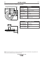
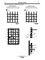
RETURN TO MAIN MENU
IM622
SF2400 STATIONARY FAN
April, 2010
Safety Depends on You
Lincoln arc welding and cutting
equipment is designed and built
with safety in mind. However,
your overall safety can be
increased by proper installation ...
and thoughtful operation on your
part. DO NOT I NSTAL L ,
OPERATE OR REPAI R THI S
EQUI PMENT WI THOUT READI NG THI S MANUAL AND THE
SAFETY PRECAUTI ONS CONTAI NED THROUGHOUT. And,
most importantly, think before you
act and be careful.
OPERATOR’S MANUAL
Copyright © Lincoln Global Inc.
• World's Leader in Welding and Cutting Products •
• Sales and Service through Subsidiaries and Distributors Worldwide •
Cleveland, Ohio 44117-1199 U.S.A. TEL: 216.481.8100 FAX: 216.486.1751 WEB SITE: www.lincolnelectric.com
i
i
SAFETY
WARNING
CALIFORNIA PROPOSITION 65 WARNINGS
Diesel engine exhaust and some of its constituents
are known to the State of California to cause cancer, birth defects, and other reproductive harm.
The Above For Diesel Engines
The engine exhaust from this product contains
chemicals known to the State of California to cause
cancer, birth defects, or other reproductive harm.
The Above For Gasoline Engines
ARC WELDING CAN bE hAzARDOUS. PROTECT YOURSELF AND OThERS FROM POSSIbLE SERIOUS INJURY OR DEATh.
KEEP ChILDREN AWAY. PACEMAKER WEARERS ShOULD CONSULT WITh ThEIR DOCTOR bEFORE OPERATING.
Read and understand the following safety highlights. For additional safety information, it is strongly recommended that you
purchase a copy of “Safety in Welding & Cutting - ANSI Standard Z49.1” from the American Welding Society, P.O. Box
351040, Miami, Florida 33135 or CSA Standard W117.2-1974. A Free copy of “Arc Welding Safety” booklet E205 is available
from the Lincoln Electric Company, 22801 St. Clair Avenue, Cleveland, Ohio 44117-1199.
bE SURE ThAT ALL INSTALLATION, OPERATION, MAINTENANCE AND REPAIR PROCEDURES ARE
PERFORMED ONLY bY QUALIFIED INDIVIDUALS.
FOR ENGINE
powered equipment.
1.h. To avoid scalding, do not remove the
radiator pressure cap when the engine is
hot.
1.a. Turn the engine off before troubleshooting and maintenance
work unless the maintenance work requires it to be running.
____________________________________________________
1.b.Operate engines in open, well-ventilated
areas or vent the engine exhaust fumes
outdoors.
____________________________________________________
1.c. Do not add the fuel near an open flame
welding arc or when the engine is running.
Stop the engine and allow it to cool before
refueling to prevent spilled fuel from vaporizing on contact with hot engine parts and
igniting. Do not spill fuel when filling tank. If
fuel is spilled, wipe it up and do not start
engine until fumes have been eliminated.
____________________________________________________
1.d. Keep all equipment safety guards, covers
and devices in position and in good
repair.Keep hands, hair, clothing and tools
away from V-belts, gears, fans and all other
moving parts when starting, operating or
repairing equipment.
____________________________________________________
1.e. In some cases it may be necessary to remove safety
guards to perform required maintenance. Remove
guards only when necessary and replace them when the
maintenance requiring their removal is complete.
Always use the greatest care when working near moving
parts.
___________________________________________________
1.f. Do not put your hands near the engine fan. Do not attempt
to override the governor or idler by pushing on the throttle
control rods while the engine is running.
___________________________________________________
1.g. To prevent accidentally starting gasoline engines while
turning the engine or welding generator during maintenance
work, disconnect the spark plug wires, distributor cap or
magneto wire as appropriate.
ELECTRIC AND
MAGNETIC FIELDS
may be dangerous
2.a. Electric current flowing through any conductor causes
localized Electric and Magnetic Fields (EMF). Welding
current creates EMF fields around welding cables and
welding machines
2.b. EMF fields may interfere with some pacemakers, and
welders having a pacemaker should consult their physician
before welding.
2.c. Exposure to EMF fields in welding may have other health
effects which are now not known.
2.d. All welders should use the following procedures in order to
minimize exposure to EMF fields from the welding circuit:
2.d.1. Route the electrode and work cables together - Secure
them with tape when possible.
2.d.2. Never coil the electrode lead around your body.
2.d.3. Do not place your body between the electrode and
work cables. If the electrode cable is on your right
side, the work cable should also be on your right side.
2.d.4. Connect the work cable to the workpiece as close as
possible to the area being welded.
2.d.5. Do not work next to welding power source.
ii
ii
SAFETY
ELECTRIC SHOCK can
kill.
3.a. The electrode and work (or ground) circuits
are electrically “hot” when the welder is on.
Do not touch these “hot” parts with your bare
skin or wet clothing. Wear dry, hole-free
gloves to insulate hands.
3.b. Insulate yourself from work and ground using dry insulation.
Make certain the insulation is large enough to cover your full
area of physical contact with work and ground.
In addition to the normal safety precautions, if welding
must be performed under electrically hazardous
conditions (in damp locations or while wearing wet
clothing; on metal structures such as floors, gratings or
scaffolds; when in cramped positions such as sitting,
kneeling or lying, if there is a high risk of unavoidable or
accidental contact with the workpiece or ground) use
the following equipment:
• Semiautomatic DC Constant Voltage (Wire) Welder.
• DC Manual (Stick) Welder.
• AC Welder with Reduced Voltage Control.
3.c. In semiautomatic or automatic wire welding, the electrode,
electrode reel, welding head, nozzle or semiautomatic
welding gun are also electrically “hot”.
3.d. Always be sure the work cable makes a good electrical
connection with the metal being welded. The connection
should be as close as possible to the area being welded.
3.e. Ground the work or metal to be welded to a good electrical
(earth) ground.
3.f. Maintain the electrode holder, work clamp, welding cable and
welding machine in good, safe operating condition. Replace
damaged insulation.
3.g. Never dip the electrode in water for cooling.
3.h. Never simultaneously touch electrically “hot” parts of
electrode holders connected to two welders because voltage
between the two can be the total of the open circuit voltage
of both welders.
3.i. When working above floor level, use a safety belt to protect
yourself from a fall should you get a shock.
ARC RAYS can burn.
4.a. Use a shield with the proper filter and cover
plates to protect your eyes from sparks and
the rays of the arc when welding or observing
open arc welding. Headshield and filter lens
should conform to ANSI Z87. I standards.
4.b. Use suitable clothing made from durable flame-resistant
material to protect your skin and that of your helpers from
the arc rays.
4.c. Protect other nearby personnel with suitable, non-flammable
screening and/or warn them not to watch the arc nor expose
themselves to the arc rays or to hot spatter or metal.
FUMES AND GASES
can be dangerous.
5.a. Welding may produce fumes and gases
hazardous to health. Avoid breathing these
fumes and gases. When welding, keep
your head out of the fume. Use enough
ventilation and/or exhaust at the arc to keep
fumes and gases away from the breathing zone. When
welding with electrodes which require special
ventilation such as stainless or hard facing (see
instructions on container or MSDS) or on lead or
cadmium plated steel and other metals or coatings
which produce highly toxic fumes, keep exposure as
low as possible and within applicable OSHA PEL and
ACGIH TLV limits using local exhaust or mechanical
ventilation. In confined spaces or in some circumstances, outdoors, a respirator may be required.
Additional precautions are also required when welding
on galvanized steel.
5. b. The operation of welding fume control equipment is affected
by various factors including proper use and positioning of
the equipment, maintenance of the equipment and the specific welding procedure and application involved. Worker
exposure level should be checked upon installation and
periodically thereafter to be certain it is within applicable
OSHA PEL and ACGIH TLV limits.
5.c. Do not weld in locations near chlorinated hydrocarbon vapors
coming from degreasing, cleaning or spraying operations.
The heat and rays of the arc can react with solvent vapors to
form phosgene, a highly toxic gas, and other irritating products.
3.j. Also see Items 6.c. and 8.
5.d. Shielding gases used for arc welding can displace air and
cause injury or death. Always use enough ventilation,
especially in confined areas, to insure breathing air is safe.
5.e. Read and understand the manufacturer’s instructions for this
equipment and the consumables to be used, including the
material safety data sheet (MSDS) and follow your
employer’s safety practices. MSDS forms are available from
your welding distributor or from the manufacturer.
5.f. Also see item 1.b.
iii
iii
SAFETY
WELDING and CUTTING
SPARKS can
cause fire or explosion.
6.a. Remove fire hazards from the welding area.
If this is not possible, cover them to prevent
the welding sparks from starting a fire.
Remember that welding sparks and hot
materials from welding can easily go through small cracks
and openings to adjacent areas. Avoid welding near
hydraulic lines. Have a fire extinguisher readily available.
6.b. Where compressed gases are to be used at the job site,
special precautions should be used to prevent hazardous
situations. Refer to “Safety in Welding and Cutting” (ANSI
Standard Z49.1) and the operating information for the
equipment being used.
6.c. When not welding, make certain no part of the electrode
circuit is touching the work or ground. Accidental contact
can cause overheating and create a fire hazard.
6.d. Do not heat, cut or weld tanks, drums or containers until the
proper steps have been taken to insure that such procedures
will not cause flammable or toxic vapors from substances
inside. They can cause an explosion even though they have
been “cleaned”. For information, purchase “Recommended
Safe Practices for the Preparation for Welding and Cutting of
Containers and Piping That Have Held Hazardous
Substances”, AWS F4.1 from the American Welding Society
(see address above).
6.e. Vent hollow castings or containers before heating, cutting or
welding. They may explode.
6.f. Sparks and spatter are thrown from the welding arc. Wear oil
free protective garments such as leather gloves, heavy shirt,
cuffless trousers, high shoes and a cap over your hair. Wear
ear plugs when welding out of position or in confined places.
Always wear safety glasses with side shields when in a
welding area.
6.g. Connect the work cable to the work as close to the welding
area as practical. Work cables connected to the building
framework or other locations away from the welding area
increase the possibility of the welding current passing
through lifting chains, crane cables or other alternate circuits. This can create fire hazards or overheat lifting chains
or cables until they fail.
6.h. Also see item 1.c.
CYLINDER may explode
if damaged.
7.a. Use only compressed gas cylinders
containing the correct shielding gas for the
process used and properly operating
regulators designed for the gas and
pressure used. All hoses, fittings, etc. should be suitable for
the application and maintained in good condition.
7.b. Always keep cylinders in an upright position securely
chained to an undercarriage or fixed support.
7.c. Cylinders should be located:
• Away from areas where they may be struck or subjected to
physical damage.
• A safe distance from arc welding or cutting operations and
any other source of heat, sparks, or flame.
7.d. Never allow the electrode, electrode holder or any other
electrically “hot” parts to touch a cylinder.
7.e. Keep your head and face away from the cylinder valve outlet
when opening the cylinder valve.
7.f. Valve protection caps should always be in place and hand
tight except when the cylinder is in use or connected for
use.
7.g. Read and follow the instructions on compressed gas
cylinders, associated equipment, and CGA publication P-l,
“Precautions for Safe Handling of Compressed Gases in
Cylinders,” available from the Compressed Gas Association
1235 Jefferson Davis Highway, Arlington, VA 22202.
FOR ELECTRICALLY
powered equipment.
8.a. Turn off input power using the disconnect
switch at the fuse box before working on
the equipment.
8.b. Install equipment in accordance with the U.S. National
Electrical Code, all local codes and the manufacturer’s
recommendations.
8.c. Ground the equipment in accordance with the U.S. National
Electrical Code and the manufacturer’s recommendations.
6.I. Read and follow NFPA 51B “ Standard for Fire Prevention
During Welding, Cutting and Other Hot Work”, available
from NFPA, 1 Batterymarch Park, PO box 9101, Quincy, Ma
022690-9101.
6.j. Do not use a welding power source for pipe thawing.
Refer to http://www.lincolnelectric.com/safety for additional safety information.
iv
SAFETY
PRÉCAUTIONS DE SÛRETÉ
Pour votre propre protection lire et observer toutes les instructions et les précautions de sûreté specifiques qui parraissent
dans ce manuel aussi bien que les précautions de sûreté
générales suivantes:
Sûreté Pour Soudage A L’Arc
1. Protegez-vous contre la secousse électrique:
a. Les circuits à l’électrode et à la piéce sont sous tension
quand la machine à souder est en marche. Eviter toujours
tout contact entre les parties sous tension et la peau nue
ou les vétements mouillés. Porter des gants secs et sans
trous pour isoler les mains.
b. Faire trés attention de bien s’isoler de la masse quand on
soude dans des endroits humides, ou sur un plancher
metallique ou des grilles metalliques, principalement dans
les positions assis ou couché pour lesquelles une
grande partie du corps peut être en contact avec la
masse.
c. Maintenir le porte-électrode, la pince de masse, le câble
de soudage et la machine à souder en bon et sûr état
defonctionnement.
d.Ne jamais plonger le porte-électrode dans l’eau pour le
refroidir.
e. Ne jamais toucher simultanément les parties sous tension
des porte-électrodes connectés à deux machines à souder parce que la tension entre les deux pinces peut être le
total de la tension à vide des deux machines.
f. Si on utilise la machine à souder comme une source de
courant pour soudage semi-automatique, ces precautions
pour le porte-électrode s’applicuent aussi au pistolet de
soudage.
2. Dans le cas de travail au dessus du niveau du sol, se protéger contre les chutes dans le cas ou on recoit un choc. Ne
jamais enrouler le câble-électrode autour de n’importe quelle
partie du corps.
3. Un coup d’arc peut être plus sévère qu’un coup de soliel,
donc:
a. Utiliser un bon masque avec un verre filtrant approprié
ainsi qu’un verre blanc afin de se protéger les yeux du
rayonnement de l’arc et des projections quand on soude
ou quand on regarde l’arc.
b. Porter des vêtements convenables afin de protéger la
peau de soudeur et des aides contre le rayonnement de
l‘arc.
c. Protéger l’autre personnel travaillant à proximité au
soudage à l’aide d’écrans appropriés et non-inflammables.
4. Des gouttes de laitier en fusion sont émises de l’arc de
soudage. Se protéger avec des vêtements de protection
libres de l’huile, tels que les gants en cuir, chemise épaisse,
pantalons sans revers, et chaussures montantes.
iv
5. Toujours porter des lunettes de sécurité dans la zone de
soudage. Utiliser des lunettes avec écrans lateraux dans les
zones où l’on pique le laitier.
6. Eloigner les matériaux inflammables ou les recouvrir afin de
prévenir tout risque d’incendie dû aux étincelles.
7. Quand on ne soude pas, poser la pince à une endroit isolé de
la masse. Un court-circuit accidental peut provoquer un
échauffement et un risque d’incendie.
8. S’assurer que la masse est connectée le plus prés possible
de la zone de travail qu’il est pratique de le faire. Si on place
la masse sur la charpente de la construction ou d’autres
endroits éloignés de la zone de travail, on augmente le risque
de voir passer le courant de soudage par les chaines de levage, câbles de grue, ou autres circuits. Cela peut provoquer
des risques d’incendie ou d’echauffement des chaines et des
câbles jusqu’à ce qu’ils se rompent.
9. Assurer une ventilation suffisante dans la zone de soudage.
Ceci est particuliérement important pour le soudage de tôles
galvanisées plombées, ou cadmiées ou tout autre métal qui
produit des fumeés toxiques.
10. Ne pas souder en présence de vapeurs de chlore provenant
d’opérations de dégraissage, nettoyage ou pistolage. La
chaleur ou les rayons de l’arc peuvent réagir avec les
vapeurs du solvant pour produire du phosgéne (gas fortement toxique) ou autres produits irritants.
11. Pour obtenir de plus amples renseignements sur la sûreté,
voir le code “Code for safety in welding and cutting” CSA
Standard W 117.2-1974.
PRÉCAUTIONS DE SÛRETÉ POUR
LES MAChINES À SOUDER À
TRANSFORMATEUR ET À
REDRESSEUR
1. Relier à la terre le chassis du poste conformement au code
de l’électricité et aux recommendations du fabricant. Le dispositif de montage ou la piece à souder doit être branché à
une bonne mise à la terre.
2. Autant que possible, I’installation et l’entretien du poste
seront effectués par un électricien qualifié.
3. Avant de faires des travaux à l’interieur de poste, la
debrancher à l’interrupteur à la boite de fusibles.
4. Garder tous les couvercles et dispositifs de sûreté à leur
place.
v
v
for selecting a QUALITY product by Lincoln Electric. We want you
to take pride in operating this Lincoln Electric Company product
••• as much pride as we have in bringing this product to you!
Thank You
Please Examine Carton and Equipment For Damage Immediately
When this equipment is shipped, title passes to the purchaser upon receipt by the carrier. Consequently, Claims
for material damaged in shipment must be made by the purchaser against the transportation company at the
time the shipment is received.
Please record your equipment identification information below for future reference. This information can be
found on your machine nameplate.
Model Name & Number _____________________________________
Code & Serial Number _____________________________________
Date of Purchase
_____________________________________
Whenever you request replacement parts for or information on this equipment always supply the information
you have recorded above.
Read this Operators Manual completely before attempting to use this equipment. Save this manual and keep it
handy for quick reference. Pay particular attention to the safety instructions we have provided for your protection.
The level of seriousness to be applied to each is explained below:
The identification plate specifies:
TYPE
SER. NR.
W.
A.
B.
C.
D.
Serial number
Product name
Power consumption
Supply voltage and frequency
WARNING
This statement appears where the information must be followed exactly to avoid serious personal injury or
loss of life.
CAUTION
This statement appears where the information must be followed to avoid minor personal injury or damage to
this equipment.
C
TAbLE OF CONTENTS
Safety
Page
.......................................................................................................................................i-iv
Installation.......................................................................................................................Section A
Technical Specifications .......................................................................................................A-1
Safety Precautions ...............................................................................................................A-3
General Description..............................................................................................................A-3
Installing with an LFA, 10ft. or 13ft. Wall-mounted Arm Package ........................................A-3
Installing with an LTA 2.0, Telescopic Arm Package ...........................................................A-7
Installing the optional Silencer............................................................................................A-10
Installing the optional Statiflex 200-M.................................................................................A-10
Installing the Starter/Overload Switch ................................................................................A-11
Installing the optional Lamp Kit and Automatic Start/Stop Arc Sensor...............................A-11
Operation.........................................................................................................................Section b
Safety Instructions ................................................................................................................B-1
Operating Instructions ..........................................................................................................B-1
Maintenance ....................................................................................................................Section C
Routine Maintenance ...........................................................................................................C-1
Trouble Shooting ............................................................................................................Section D
Trouble Shooting Chart ........................................................................................................D-1
Wiring Diagram ...............................................................................................................Section E
Wiring Diagram for SF2400 Fan with K1494-2 Starter/Overload Switch..............................E-1
Wiring Diagram for SF2400 Fan with K1669-2 Lamp Kit .....................................................E-2
Parts Manual ..................................................................................................................Appendix
Parts Pages ..........................................................................................................................1-4
vi
A-1
A-1
INSTALLATION
Technical Specifications- SF2400 Stationary Fan
11"
(275 mm)
9"
(225 mm)
6.5" (167 mm)
9"
(230 mm)
Ø6.3" (Ø160 mm)
10"
(250 mm)
5"
(130 mm)
GENERAL
Sales Spec.
K1656-1
Input Voltage
115V, 1 Ph, 60 Hz
Rated Current Draw
9.4 A
Power Rating
0.75 kW
Sound Level
69 dB(A)
Weight
28 lbs. (14 kg)
AMbIENT CONDITIONS
o
41 F (5 C)
Max. Temperature
113 F (45 C)
Max. Rel. humidity
o
o
80%
3"
(70 mm)
12"
(300 mm)
Ø6.3"
(160 mm)
o
Min. Temperature
C
NOTE: Technical Specifications are subject to change without prior notice. Specifications and guarantees are
valid only when specified spare parts and filters are used.
SF2400 STATIONARY FAN
A-2
A-2
INSTALLATION
Technical Specifications- SF2400 Stationary Fan
PRESSURE DROP
SF2400 Fan and LFA 3.1/4.1 Arms
PRESSURE DROP
SF2400 Fan and LTA 2.0 Arm
Vacuum (inches WG) vs. Airflow (CFM)
Vacuum (inches WG) vs. Airflow (CFM)
Vacuum
(Inches WG)
Vacuum
(Inches WG)
SF 2400
SF 2400
6
6
4
4
LTA 3.1/4.1
2
2
LTA 2.0
Vacuum
(Inches WG)
SF 2400
6
4
2
LTA 2.0
0
0
250
500
750
1000
Air Flow (CFM)
0
0
0
250
500
750
0
1000
250
500
750
1000
Air Flow (CFM)
Air Flow (CFM)
20 ft.
45°
16 ft.
40"
(1000 mm)
13 ft.
10 ft.
55"
(1400 mm)
6 ft.
3 ft.
Vacuum
(Inches WG)
SF 2400
6
4
LTA 3.1/4.1
2
0
0
250
500
750
1000
Air Flow (CFM)
0 ft.
0 ft.
3 ft.
6 ft.
10 ft.
13 ft.
45°
40"
(1000 mm)
40"
(1000 mm)
55"
(1400 mm)
SF2400 STATIONARY FAN
A-3
A-3
INSTALLATION
Read this entire installation section before you
start installation.
SAFETY PRECAUTIONS
Do not attempt to use this equipment until you have
thoroughly read all installation, operating and maintenance information supplied with your equipment. They
include important safety precautions and detailed
operating and maintenance instructions.
WARNING
ELECTRIC ShOCK can kill.
• Do not touch electrically live parts such
as internal wiring.
• Turn the input power off at the fuse box
before working on this equipment.
• Have a qualified person install and service this equipment.
-----------------------------------------------------------------------MOVING PARTS can injure.
• Do not operate with covers open or filter removed.
• Keep away from moving parts.
-----------------------------------------------------------------------Only qualified personnel should install, use or service
this equipment.
GENERAL DESCRIPTION
The K1656-1 SF2400 Stationary Fan provides a low
vacuum, high volume airflow for fume extraction and
ventilation applications. It is intended for use with
large diameter (6-8 in.) flexible arms or hoods.
The SF2400 fan is most commonly used with the LFA
3.1/4.1, 10 ft. and 13 ft. spring-balanced, articulated
arms or LTA 2.0, 3-5 ft. Telescopic Arm (for small
booth or workstation applications). Extracted air can
be vented outside through an Air Exhaust Silencer, or
filtered through a Statiflex 200-M Wall-Mounted Filter
Unit. The Starter/Overload Switch for the SF2400
Extraction Fan protects the motor against overcurrent.
The optional Lamp Kit for Wall-Mounted Systems provides a work lamp, remote hood-mounted switches for
the lamp and extraction fan, and overload protection,
(thus replacing the starter/overload switch). The
Automatic Start/Stop Arc Sensor can be installed with
the Lamp Kit to turn the extraction fan on and off automatically when an arc flash is detected. Extension
Cranes in 7ft. and 14 ft. lengths, and a Feeder
Hanging Rail for use with extension cranes further
expand system possibilities.
Available Equipment:
K1655-1 LFA 3.1, 10 ft. Extraction Arm
K1655-2 LFA 4.1, 13 ft. Extraction Arm
K1655-3 LTA 2.0, Telescopic Extraction Arm
K1534-2 Air Exhaust Silencer
K1654-1 Statiflex 200-M, Wall-mounted Filter Unit
K1494-2 Starter/Overload Switch
(unnecessary if using a K1669-2 Lamp Kit)
K1669-2 Lamp Kit for Wall-Mounted Systems
(replaces K1494-2 Starter/OL Switch)
K1670-1 Automatic Start/Stop Arc Sensor
(requires K1669-2 Lamp Kit)
K1671-1 Extension Crane, 7 ft.
K1671-2 Extension Crane, 14 ft.
K1672-1 Feeder Hanging Rail for Extension Crane
INSTALLING WITh AN LFA 10FT. OR
13FT. WALL-MOUNTED PACKAGE
WARNING
The installer is responsible for following local safety
codes and regulations.
-----------------------------------------------------------------------Before drilling, verify locations of existing gas, water,
or electrical conduits.
-----------------------------------------------------------------------K1655-1 LFA 3.1 or K1655-2 LFA 4.1 Arm Includes:
• Assembled arm, 2 sections
• Flexible hose, (2) 8” Rubber seals for hood hinge
• Hood assembly
• (2) Bolts, M8x1.25, 45mm long (about 1.75”)
• (2) Nuts, M8 self-locking
• Hose running guard
• Clamping pin for red plastic ring
• Metal rotating hinge
• Red plastic ring
K1657-1 Wall Mounting Bracket Includes:
• (2) Bracket pieces
• Hanging Adapter
• Spring Bracket
• Flexible Hose, (2) 8” Rubber bands for arm base
• (2) Bolts, M8x1.25, 45mm long (about 1.75”)
• (4) Bolts, M8x1.25, 75mm long (about 3.00”)
• (6) Nuts, M8 self-locking
• (6) Washers, M8
K1656-1 SF2400 Stationary Fan Includes:
• SF2400 Stationary Fan
• (2) Bolts, M8x1.25, 20mm long (about 0.75”)
• (2) Bolts, M8x1.25, 65mm long (about 2.50”)
• (4) Washers, M8
Note: K1494-2 Starter/Overload or K1669-2 Lamp Kit
must be installed with this package. See the installation section later in this manual for details on installing
this equipment.
SF2400 STATIONARY FAN
A-4
A-4
INSTALLATION
6.3" (160 mm)
INSTALLING WITh AN LFA 10FT. OR
13FT. WALL-MOUNTED PACKAGE
(continued)
8.3"
(210 mm)
MOUNTING THE WALL-MOUNTING BRACKET
(continued)
Standard mounting height is approximately 8 ft., 2 in.
from the floor to the top of the wall mounting bracket.
Refer to Fig. 1 for drilling dimensions.
Refer to the Fig. 2 for recommended mounting
methods for installation on various wall types.
A. Mounting on a thin wall (recommended minimum
wall thickness 5 in. (100 mm)), using four threaded
rods, 3/8 in. (M10)
B. Mounting on a thick wall using four cotter bolts
3/8 in. (M10)
C. Mounting on a steel I-beam using four threaded
rods 3/8 in. (M10) and two box-profile
stabilizers (1x1x0.1 in., 30x30x3 )
Fig.
A
9" (230 mm)
Fig. 1
2
C
3/8"
3/8"
8.3"
(210 mm)
6.3" (160 mm)
B
9" (230 mm)
3/8"
3/8"
SF2400 STATIONARY FAN
A-5
A-5
INSTALLATION
INSTALLING WITh AN LFA 10FT. OR
13FT. WALL-MOUNTED PACKAGE
(continued)
MOUNTING THE LFA 3.1 OR 4.1 ARM TO THE
WALL-MOUNTING BRACKET
Leave the tape and plastic packaging on the extraction arm sections until the arm is completely installed
(including mounting the hood). The arm is spring-balanced to compensate for the weight of the hood and
will spring out quickly if it is not mounted securely,
with the hood in place.
Mount the hanging adapter (Fig. 5D) to the hinge rod
(Fig. 5C) using (2) 1.75” bolts with washers and nuts.
Mount the spring bracket (Fig. 5F) into the two holes
as shown. Position one 8” rubber seal (Fig. 5A) on the
red plastic ring. Roll the bottom half up and slide the
connecting hose (Fig. 5E) over the bottom of the red
plastic ring. Roll the bottom of the rubber seal down
over the end of the connection hose.
A
B
C
D
The rotating hinge of the arm comes in three pieces:
Metal rotating hinge, red plastic ring, and clamping
pin. Refer to Figure 3. Mount the red plastic ring to the
metal rotating hinge by fitting the clamping pin through
the hole in the rotating rod, and snapping it into place
on the U-shaped indents on the red plastic ring. The
lip of the ring should fit securely against the top edge
of the rotating flange, yet rotate with the rod. The
assembly should look like Part C in Figure 4.
E
F
Fig. 5
Put another rubber band on the base of the arm. Use
(2) 1.75” bolts with nuts to mount the arm (Fig. 6B) to
the hanging adapter (Fig. 6A), using both mounting
holes as shown in the inset of Figure 6.
2
1
3
A
B
Fig. 3
Position the rotating hinge on the wall mounting bracket (See Fig. 4) so that the cable hole (Fig. 4A) is on
the wall side and the long side of the pin (Fig. 4B) is in
the front. Use the four 3” bolts with washers and nuts
to secure the rotating hinge.
A
B
C
D
E
F
C
A
Fig. 6
B
E
D
Fig. 4
E
SF2400 STATIONARY FAN
A-6
A-6
INSTALLATION
INSTALLING WITh AN LFA 10FT. OR
13FT. WALL-MOUNTED PACKAGE
(continued)
MOUNTING THE LFA 3.1 OR 4.1 ARM TO THE
WALL-MOUNTING BRACKET
(continued)
Position one 8” rubber seal (Fig. 7B) and the flexible
hose supplied with the arm (Fig. 7C) on the hood end
of the arm (Fig. 7A). Put the last rubber seal on the
hood connection. Mount the friction block into the Usection, using one bolt and nut as shown in
Figure 7.
Remove the plastic and tape from the arm sections.
Adjust the friction of the arm and hood movement as
described in the Maintenance Section of the LFA
Extraction Arm Manual.
MOUNTING THE SF2400 FAN TO THE WALL
MOUNTING BRACKET
Use the (2) 0.75” bolts and the (2) 2.5” bolts with
washers supplied with the fan to mount the fan
(Fig. 9B) to the rotating hinge (Fig. 9C) as shown.
Tighten all mounting bolts firmly to make the seal at
the inlet of the fan.
A
A
B
C
B
C
D
Fig. 9
Fig. 7
Snap the hose running guard into place atop the middle hinge section so the “nose” end faces the base of
the arm as shown in Figure 8.
The K1494-2 Starter/Overload Switch or K1669-2
Lamp Kit must be installed to provide power to the
fan. Refer to the appropriate Installation section in this
manual for details.
C
C(2x)
Fig. 8
A
B
C
C
SF2400 STATIONARY FAN
A-7
A-7
6.3" (160 mm)
INSTALLATION
INSTALLING WITh AN LTA 2.0,
3-5 FT. TELESCOPIC ARM
WARNING
8.3"
(210 mm)
The installer is responsible for following local safety
codes and regulations.
-----------------------------------------------------------------------Before drilling, verify locations of existing gas, water,
or electrical conduits.
-----------------------------------------------------------------------K1655-3 LTA 2.0 Telescopic Arm Includes:
• Telescopic arm, assembled
• (1) Flexible hose, (2) 8” Rubber seals
for connection to fan
9" (230 mm)
Fig. 11
K1657-1 Wall Mounting Bracket Includes:
• (2) Bracket pieces
• Tapered Connection Flange
• 8” Hose Clamp
9"
(230 mm)
4.7"
(120 mm)
K1656-1 SF2400 Stationary Fan Includes:
• SF2400 Stationary Fan
• (2) Bolts, M8x1.25, 20mm long (about 0.75”)
• (2) Bolts, M8x1.25, 65mm long (about 2.50”)
• (4) Washers, M8
0.4"
(10 mm)
ø0.5"
(ø13 mm)
Note: K1494-2 Starter/Overload or K1669-2 Lamp Kit
must be installed with this package. See the appropriate Installation section in this manual for details on
this equipment.
8.3"
(210 mm)
10"
(255 mm)
Fig. 12
MOUNTING THE MOTOR-MOUNTING BRACKET
AND TELESCOPIC ARM
Drill (5) holes (Reference Figures 11, 12, 13).
Disconnect the telescopic mounting bracket from the
arm before mounting, by removing the 1.75” bolt (Fig.
12C), and sliding the post out of the friction block.
Mount the motor mounting bracket and the telescopic
mounting bracket to the wall. Standard mounting
height is 5 ft., 3 in. (1300 mm) from the work table to
the post of the telescopic mounting bracket. Refer to
Figures 11 and 12 for drilling dimensions.
A
8.3"
(210 mm)
6.3" (160 mm)
Refer to Figure 2 for information on mounting methods
for installation on various wall types.
9" (230 mm)
C
C
B
Fig. 13
Fig. 10
SF2400 STATIONARY FAN
9"
(230 mm)
4.7"
(120 mm)
0.4"
(10 mm)
ø0.5"
(ø13 mm)
8.3"
(210 mm)
10"
(255 mm)
C
A-8
A-8
INSTALLATION
INSTALLING WITh AN LTA 2.0,
3-5 FT. TELESCOPIC ARM
ADJUSTING THE FRICTION POSITIONING
The amount of friction resistance should be set such
that the arm is comfortable to move (always test both
up and down movements), yet hold its position against
gravity once positioned.
(continued)
MOUNTING THE MOTOR-MOUNTING BRACKET
AND TELESCOPIC ARM
(continued)
Remount the telescopic arm on the telescopic mounting bracket by sliding the friction block over the post of
the bracket and securing with the 1.75” bolt and nut
(Refer to Figure 10).
To adjust the friction resistance of the hood movement, fold back the rubber band onto the hood, and
push up the flexible hose, exposing the connection
blocks. Use an 8mm wrench to adjust both bolt/nut
pairs as shown in Fig. 15.
MOUNTING THE EXTRACTION FAN TO THE
MOTOR MOUNTING BRACKET
Position the tapered connection flange (Fig. 14C) on
the motor mounting brackets; use the (2) 0.75” and
(2) 2.5” bolts with washers (supplied with the fan) to
secure the fan (Fig. 14B) and the connection flange to
the motor mounting brackets. Tighten all bolts securely to make a good seal on the inlet of the fan.
B
B
B
A
Fig. 15
B
C
D
Fig. 14
Position one of the 8” rubber seals supplied with the
arm on the largest part (8” diam.) of the tapered connection flange. Roll the bottom of the rubber seal up,
and slide one end of the 4 ft. connection hose (supplied with the arm) up over the tapered connection
flange until it butts up against the folded side of the
rubber seal. Fold the rubber seal down over the hose.
Secure the connection with one 8” hose clamp. Apply
the other 8” rubber seal and the other end of the hose
to the top of the telescopic arm tube.
The K1494-2 Starter/Overload Switch or K1669-2
Lamp Kit must be installed to provide power to the
fan. Refer to the appropriate Installation section in this
manual for details.
SF2400 STATIONARY FAN
B
B
B
C
C
C
A-9
INSTALLATION
INSTALLING WITh AN LTA 2.0,
3-5 FT. TELESCOPIC PACKAGE
(continued)
ADJUSTING THE FRICTION POSITIONING
(continued)
The amount of friction resistance should be set such
that the arm is comfortable to move (always test both
up and down movements), yet hold its weight against
gravity once positioned.
To adjust the friction setting for front to back movement, adjust the front bolt/nut set (Fig. 16E) on the
rotating hinge.
To adjust the friction setting for the telescopic motion
of the arm, remove the black cap (Fig. 16B) and turn
the set screw (Fig. 16D):
Counterclockwise to increase friction and
Clockwise to decrease it.
NOTE: Friction is only applied to the telescopic movement when pulling the hood down; gravity provides
resistance when lifting the hood.
To adjust the friction setting for side to side movement
of the arm, use the top two bolt/nut sets on the rotating hinge (Fig. 16A).
Fig. 16
B
C
D
E
A-9
A
SF2400 STATIONARY FAN
A-10
A-10
INSTALLATION
INSTALLING ThE SILENCER
Mount the Statiflex mounting bracket (Fig. 17A) to the
wall where convenient with the following in mind:
A
The K1534-2 6” silencer can be used on the outlet of
the SF2400 stationary fan to reduce airflow noise levels.
The K1534-2, 6” Air Exhaust Silencer Includes:
• Air Exhaust Silencer, with 6” (160 mm) connections
• Elbow, 90˚, with 6” (160 mm) connections
• (2) Fittings, to fit on the OD of the:
Outlet of the SF2400 Fan
Elbow, 90˚
Air Exhaust Silencer
Install the silencer and the connecting ductwork into
the outlet of the fan. If venting extracted air outside,
apply the supplied ductwork between the fan and
silencer, then use 160 mm (6.3 in.) ductwork or flexible hose to route the exhausted air outside through a
hole in the wall or roof.
INSTALLING ThE OPTIONAL
STATIFLEX 200-M
The Statiflex 200-M Wall-Mounted Filter Unit can be
installed to filter the exhausted air before it is recirculated or exhausted outside. The Air Exhaust Silencer
is unnecessary when a Statiflex 200-M Filter is used.
E
11.4"
(290 mm)
Fig. 17
• Access to the filter (for maintenance) is by lifting the
large red cover over the (internal) filter. The easiest
method is to lift the entire filter unit off the mounting
bracket (about 2-4” higher than its mounting height)
and set it down on the floor, then perform any necessary maintenance.
• The 8” connection hose must reach (comfortably)
the inlet of the Statiflex 200-M; the inlet (when mounted) is approximately 10 in. off the left side of the
Statiflex mounting bracket.
• The Statiflex 200-M may be mounted on either side
of the fan, as long as the connection hose reaches
from the outlet of the fan to the inlet of the Statiflex
200-M.
• Recommended mounting height of the Statiflex
mounting bracket is less than 7 ft. from the floor to the
drilled holes. It is recommended to mount the bracket
about 30-36 in. off the outlet of the fan (to the right).
Before lifting the Statiflex 200-M Filter Unit onto the
mounting bracket:
• Cut the left inlet (or right, depending on which side
of the fan it is to be mounted) open (See C). A hacksaw or multi-purpose power saw may be used.
• Unscrew the thumb nut and remove the filter cover
(See D). Cut one or both outlet openings (See E)
open. Replace the filter cover and thumb nut.
D
B
A
C
The K1654-1 Statiflex 200-M Filter Unit Includes:
• Complete Filter Unit, with filter installed and
inlet(s) and outlet(s) sealed
• Reducer, 6”-8”
• 8” Connection hose, 4 ft. long
• (2) 8” Hose Clamps
Lift the Statiflex 200-M onto the mounting bracket;
refer to Figure 18. The installation may be made permanent by running (2) self-tapping screws (FIg. 18E)
in through the plastic base against the wall bracket.
A
B
C
A
11.4"
(290 mm)
Fit the small (6” diam.) side of the 6”-8” Reducer over
the outlet of the SF2400 Fan (See A); be sure to slide
the Reducer all the way over the rubber seal. Secure
with three sheet-metal screws through the reducer
into the plastic-molded fan outlet.
Fit one end of the 8” Connection hose (See B) over
the larger side of the 6”-8” Reducer. Secure with one
8” hose clamp.
C
E
D
SF2400 STATIONARY FAN
Fig. 18
A-11
A-11
INSTALLATION
If installing the Automatic start/stop arc sensor:
Use a small phillips-head screwdriver to remove the
six screws that hold the lamp housing (Fig. 20A)
together. Insert the sensor (Fig. 20B) as shown. Route
the leads through the lamp housing and out with the
lamp leads as shown in Figure 20. Reclose the lamp
housing using the six screws.
INSTALLING ThE STARTER/OVERLOAD SWITCh
The K1494-2 Starter/Overload switch is used to turn
on and off the SF2400 Stationary fan. It is unnecessary if using a K1669-2 Lamp Kit.
Mount the switch to the wall in a location convenient
to the operator.
A
B
Route a 120VAC, 1ph, 60hz supply cable into the
switch compartment, and a power cable between the
switch and the extraction fan. Have a qualified electrician make connections per the wiring diagram in the
back of this manual. Set the Overload to 10.0A.
INSTALLING ThE OPTIONAL
LAMP KIT AND AUTOMATIC
START/STOP ARC SENSOR
An optional K1669-2 Lamp Kit for wall-mounted units
provides hood-mounted switches for both lamp and
SF2400 Extraction Fan. It is used in place of the
Starter/Overload switch, and can be combined with a
K1670-1 Automatic start/stop arc sensor to automatically switch the extraction fan on and off when it senses an arc. Installation instructions include directions
for mounting both the Lamp Kit and Sensor. If not
installing the Auto start/stop feature, skip steps as
indicated.
C
Fig. 20
Feed the lamp and/or sensor leads through the hole
(Fig. 21A) in the top of the hood, and snap the lamp
holder into place, top end first. Remount the airflow
focus vanes in the open end of the hood.
A
B
The K1669-2 Lamp Kit includes:
Work Lamp (WL)
36 ft. Connection Cable (NCW 11)
Connection Box (CB)
Thermal Relay, 8-12.5A (NTR)
Pop out the sealing plate (Fig. 19A) on the top of the
hood with a screwdriver. Remove the six screws (Fig.
19C) and the airflow focus vanes (Fig. 19B). Open the
airflow throttle valve (Fig. 19D).
A
B
C
1
A
B
Fig. 21
90°
3
6x
2
D
Fig. 19
C
SF2400 STATIONARY
FAN
C
V
C
A-12
A-12
INSTALLATION
If installing with an LTA 2.0 Telescopic Arm:
With the arm fully extended, route the 36 ft. connecting cable through the arm, securing it to the guide arm
in two places with cable ties as shown in Figure 24.
Exit the arm through the hole near the rotating hinge
(Fig. 24A); use a knife to cut an X-pattern in the grommet as shown in the inset. Loosely secure the cable to
the post of the mounting bracket as shown.
INSTALLING ThE OPTIONAL
LAMP KIT AND AUTOMATIC
START/STOP ARC SENSOR
(continued)
Roll back the rubber seals on each flexible hose joint
in the arm, to allow access to the arm mechanism.
Feed the 36 ft. connecting cable through the hole in
the hood (Fig. 22B).
4
3
B
A
A
C
2
B
1
B
Fig. 24
Fig. 22
Have a qualified electrician connect the 36 ft. connecting cable, lamp cable, and sensor cable (if used) to
the control board (Fig. 23B). Snap the board onto the
bottom of the remote switch (Fig. 23C). Snap the
switch box (Fig. 23A) into the top of the hood by
squeezing the front and back.
A
C
K
C
B
WH
BN
P
LAM
B
H
W
N
N
G
B
K
C
IMS
GN
B
Connecting
Cable
TO:
Auto
Sensor
4
3
B
A
C
2
B
1
D
C
D
TO:
Lamp
Fig. 23
SF2400 STATIONARY FAN
A-13
A-13
INSTALLATION
L=min. 22"
INSTALLING ThE OPTIONAL
LAMP KIT AND AUTOMATIC
START/STOP ARC SENSOR
(550 mm)
(continued)
If installing with a 10 ft. or 13 ft. Arm:
Route the 36 ft. connecting cable through the four
cable holders in the arm (Fig. 26D). Leave plenty of
slack at each hinge (Fig. 26A) (22 in. at the middle
hinge).
Secure the cable in the cable holders (Fig. 26-Inset),
and use wire ties at the hinge as shown in Fig. 25.
Exit the arm through the cable hole in the rotating
hinge; use a knife to cut a small X-pattern in the grommet as shown in Figure 24.
A
B
Fig. 25
Fig. 26
A
C
C
D
D
D
L=min. 22"
(550 mm)
C
4x
D
SF2400 STATIONARY FAN
A
A-14
A-14
INSTALLATION
Mount the connection box to the wall using four
screws as shown in Figure 28.
INSTALLING ThE OPTIONAL
LAMP KIT AND AUTOMATIC
START/STOP ARC SENSOR
A
(continued)
INSTALLING THE CONTROL BOX
Mount the Thermal Relay (Fig. 27A) to the Contactor
(Fig. 27D) by snapping the pin on the bottom of the
Thermal Relay into the hole in the top of the
Contactor. The three shorting pins at the bottom of the
Thermal Relay should connect into terminals 2T1,
4T2, and 6T3 of the Contactor. Tighten the screw connections at 2T1, 4T2, and 6T3, and have a qualified
electrician make the remaining connections inside the
Control Box per the wiring diagram in the back of this
manual. (NOTE the orientation of the control box
when referencing Figures 27, 28, and the wiring diagram).
TYPE
SER.
NR
.
ALK
MAA
R-
HOL
LAN
D
W.
D
C
B
A
Fig. 28
Feed a 120VAC, 1ph, 60Hz supply cable into the
Control Box. Route a power cable out of the box, to
the terminal box on the motor of the SF2400 fan.
Route the 36 ft. connection cable into the Control Box.
C
Connect
all cables per the wiring diagram in the back
of this manual.
C
B
D
A
TYPE
SER.
ALKMAAR
NR.
- HOLLAND
W.
D
C
B
Fig. 27
C
Make sure the thermal relay is always in manual operation by setting the blue button (Fig. 27C) at H. Check
also that the thermal relay is set to 10.0A.
PLEASE NOTE:
It is not necessary to use the K1669-2 Lamp Kit in
conjunction with a K1494-2 Starter/Overload Switch.
SF2400 STATIONARY FAN
b-1
OPERATION
b-1
Read and understand this entire section before operating your SF2400 Stationary Fan System.
Only qualified personnel should operate this equipment.
SAFETY INSTRUCTIONS
ADDITIONAL SAFETY PRECAUTIONS
Do not attempt to use this equipment until you have
thoroughly read all operating and maintenance manuals supplied with your equipment and any related
welding machine it will be used with. They include
important safety precautions, operating and maintenance instructions and parts lists.
Always operate this equipment with the filter and arm
installed and all covers in place as these provide maximum protection from moving parts and insure proper
vacuum operation and cooling air flow.
OPERATING INSTRUCTIONS
Use the wall-mounted starter/overload switch or the
hood-mounted remote switch (if a lamp kit is installed)
to turn on the SF2400 Stationary Fan.
WARNING
ELECTRIC ShOCK can kill.
•Do not touch electrically live parts such
as output terminals or internal wiring.
•Insulate yourself from the work and
ground.
•Always wear dry insulating gloves.
-----------------------------------------------------------------------WELDING SPARKS can cause fire or
explosion.
•Keep flammable material away.
•Do not weld upon containers which
have held combustibles.
-----------------------------------------------------------------------ARC RAYS can burn.
•Wear eye, ear and body protection.
------------------------------------------------------------------------
FUMES AND GASES
can be dangerous.
• Although the removal of the particulate matter from welding smoke may
reduce the ventilation requirement,
concentrations of the clear exhausted
fumes and gases may still be hazardous to health. Avoid breathing
concentrations of these fumes and
gases. Use adequate ventilation
when welding. See ANSI Z49.1,
"Safety in Welding and Cutting", published by the American Welding
Society.
------------------------------------------------------------------------
Position hood within 10-15 inches (250-400 mm) of
the arc.
If using a Lamp Kit:
• The switch on the hood with a lamp symbol
operates the work lamp in the hood.
• The 0/1 switch operates the SF2400 Fan.
If using an Auto Start/Stop Arc Sensor:
Leave the 0/1 switch in the 0 (off) position. The arc
sensor will automatically switch the fan on when it
senses an arc. Standard run-out time is approximately
20 sec. The work lamp operates independently of this
sensor.
If using a Statiflex 200-M filter unit:
DO NOT USE FOR CUTTING OR GOUGING OPERATIONS. The Statiflex filter unit is recommended for
light duty or intermittent use. Although it can be used
in production applications, this may require very frequent maintenance or replacement of the filter cartridge. Use of the Statiflex 200-M disposable filter system is cost effective if consumable use at the station
is less than 1500 lbs. per year of solid wire or 1100
lbs. per year of flux-shielded consumables.
STATIFLEX FILTER MAINTENANCE INDICATOR
With use, the filter will fill up with collected fume.
When using the machine, regularly check the maintenace indicator on the front panel of the machine. The
indicator will move gradually from white to red as the
filter becomes saturated, letting you know ahead of
time how close the filter is to clogging.
When the maintenance indicator shows that the filter
is clogged, it is time to replace the filter.
SF2400 STATIONARY FAN
C-1
MAINTENANCE
ROUTINE MAINTENANCE
Every 12 months, have a qualified technician check
the blower fan and housing for encrusted particles and
clean if necessary. Check the sealing material of the
extraction fan and replace if necessary.
If used, refer to the Statiflex 200-M, Extraction arm,
Extension crane, Lamp kit, and Auto start/stop arc
sensor manuals for required routine maintenance
operations.
SF2400 STATIONARY FAN
C-1
D-1
D-1
TROUbLEShOOTING
Observe all Safety Guidelines detailed throughout this manual
SYMPTOM
Motor does not start.
PRObLEM
SOLUTION
No input power.
Verify 120VAC/60Hz, 1ph input power.
Input cord damaged.
Check the integrity of the input cord.
Loose contacts.
Check the contacts.
Starter/overload switch damaged or
defective.
Repair or replace the starter/overload
switch in the control panel.
Motor damaged or defective.
Repair or replace the motor.
Motorhums, but no suction.
Motor capacitor defective or not
connected.
Replace the motor capacitor.
Motor stops automatically.
Motor overload protection activated. Let the machine cool down for a few
minutes.
Motor defective or damaged.
Repair or replace the motor.
Leakage.
Check hose connections and integrity
Outlet grid blocked.
Remove obstructions from outlet grid.
Air path in arm blocked.
Remove obstructions from arm.
Filter blocked (check Maintenance
Indicator).
Replace filter.
Spark arrester blocked.
Clean the spark arrester.
Blower fan blocked.
Clean excess fume or spatter from fan.
Fan seal damaged.
Check or replace sealing material of fan.
Dust or smoke coming out of outlet.
Filter damaged, or not seated correctly.
Replace the filter or reseat it.
Vibrations in the machine.
Imbalance in the fan.
Clean excess dirt from fan.
Poor suction.
CAUTION
If for any reason you do not understand the test procedures or are unable to perform the tests/repairs safely, contact your
Local Lincoln Authorized Field Service Facility for technical troubleshooting assistance before you proceed.
SF2400 STATIONARY FAN
E-1
GND
L
N
L
to the specific motor type.
wiring instructions that pertain
See motor (terminal cover) for
FAN MOTOR
GND
GND
L
N
L
2/T1
4/T2
STOP
10
6/T3
SWITCH
STARTER/OVERLOAD
START
61
31
1/L1
L
3/L2
L
5/L3
N
GND
N
L
GND
N
L
115V/1PH/60HZ
INPUT POWER
L
N
GND
N
GND
L
INPUT POWER
115V/1PH/60HZ
N
L
1/L1
3/L2
5/L3
STARTER/OVERLOAD
SWITCH
13
10
16
WIRING DIAGRAM FOR SF2400 FAN WITh K1494-2 STARTER/OVERLOAD SWITCh
E-1
DIAGRAMS
START
STOP
2/T1
4/T2
6/T3
L
L
GND
N
GND
FAN MOTOR
N
L
GND
See motor (terminal cover) for
wiring instructions that pertain
to the specific motor type.
SF2400 STATIONARY FAN
E-2
WORK LAMP
GND - Green/Yellow
WH - White
GN - Green
BK - Black
BL - Blue
BN - Brown
REMOTE SWITCH
WH
BN
WH
BN
I/O
GN
GN
E-2
DIAGRAMS
GND - Ground
N - Neutral
L - Line (115VAC/1PH/60HZ)
WIRE COLOR CONVENTIONS
KB
NB
NG
N.C.
HW
KB
LAMP
LAMP
to the s pe c ific m otor ty pe .
wir ing ins tr uc tions tha t pe r ta in
Se e m otor (te r m ina l c ov e r ) for
N.D.
N
BN
ELBAC .TF 63
GN
WH
ARC SENSOR
AUTO START/STOP
L
FA N MOTOR
L
N
L
GND
N.D.
L
N.D.
GND
L
115V/1PH/60HZ
INPUT POWER
L
N
GND
N
GND
N
N
N
L
GND
FUSE
WH
GN
LUG
BN
BN
GROUND
N.D.
GN/YE
GND
N.B.
BK
N.B.
BN
WH
BN
GN
BL
GN/YE
BN
BL
T1
BK
T2
N.A.
T3
RD
96
98
97
95
GN
MAN
AUTO
BL
BN
A2
BK
2T1
400V
BK
BK
4T2
1
BK
A2
22
6T3
3
4
N.A.
01E
GN
GN
BN
BN
SERIE: 9740
TR 188.83
1
BK
1L1
3
3L2
4
5L3
AEG
21
TRANSFORMER
A1
L
N
BN
ROTCATNOC
230V
Primair
AEG
RD
BN
48VA
SEC. 24V
115V
01
b27T
BL
0
YALER
N.B.
BN
BN
GN/YE
GN
BN
WH
LAMREHT
BN
BN
L
N
BOX
CONTROL
N.D. WIRES LABELED L, N, AND GND TO BE PROVIDED AND INSTALLED BY CUSTOMER.
N.C. LAMP WIRES ARE WHITE WITH BLACK SLEEVES.
WITH SMALL SCREWDRIVER, AND INSERT WIRE IN CORRESPONDING TOP OPENING.
N.B.
TO INSERT CONDUCTORS IN TERMINAL BLOCK, PUSH IN ON FRONT OPENING
N.A.
MOUNT THERMAL RELAY TO CONTACTOR AS DESCRIBED IN INSTALLATION SECTION.
NOTES:
NOTES:
N.A. MOUNT THERMAL RELAY TO CONTACTOR AS DESCRIBED IN INSTALLATION SECTION.
N.B. TO INSERT CONDUCTORS IN TERMINAL BLOCK, PUSH IN ON FRONT OPENING
WITH SMALL SCREWDRIVER, AND INSERT WIRE IN CORRESPONDING TOP OPENING.
N.C. LAMP WIRES ARE WHITE WITH BLACK SLEEVES.
N.D. WIRES LABELED L, N, AND GND TO BE PROVIDED AND INSTALLED BY CUSTOMER.
N
L
L
N
BN
A1
TRANSFORMER
1L1 3L2
TR 188.83
21
5L3
1
3
4
CONTACTOR
BK
CONTROL
BOX
AEG
SERIE: 9740
BN
BN
GN
SEC. 24V
48VA
1
BK
3
4T2
2T1
BL
RD
10
AUTO
WH
MAN
BN
N.B.
BN
BN
BN
RELAY
AEG
b27T
BN
A2
BK
BK
A2
N.A.
22
6T3
BK
BN
01E
4
GN
WH
BN
GN
98
96
GN
97
95
GN
RD
GN/YE
T1
GN/YE
BL
N.B.
THERMAL
BN
BL
T2
BL
BN
N.A.
T3
BN
BK
BK
N.B.
GND
GN/YE
GROUND
N.D.
L
LUG
BN
BN
FUSE
WH
GN
GND
N
N
AUTO START/STOP
ARC SENSOR
GN
BN
36 FT. CABLE
WH
LAMP
L
GND
L
N.D.
N
L
N.D.
N
L
GND
INPUT POWER
115V/1PH/60HZ
FAN MOTOR
L
N
GND
N
L
See motor (terminal cover) for
wiring instructions that pertain
to the specific motor type.
BN
GN
WH
BK
N
GND
N.D.
N.C.
BK
WIRING DIAGRAM FOR SF2400 FAN WITh K1669-2 LAMP KIT
Primair
0 115V 230V
400V
LAMP
I/O
GN
BN
REMOTE SWITCH
WORK LAMP
WH
BN
WH
GN
WIRE COLOR CONVENTIONS
BN - Brown
BL - Blue
BK - Black
GN - Green
WH - White
GND - Green/Yellow
SF2400 STATIONARY FAN
L - Line (115VAC/1PH/60HZ)
N - Neutral
GND - Ground
NOTES
SF2400 STATIONARY FAN
l D o not touch electrically live parts or
WARNING
Spanish
AVISO DE
PRECAUCION
l K eep flammable materials away.
l W ear eye, ear and body protection.
l M antenga el material combustible
l Protéjase los ojos, los oídos y el
electrode with skin or wet clothing.
l I nsulate yourself from work and
ground.
l N o toque las partes o los electrodos
bajo carga con la piel o ropa mojada.
l A islese del trabajo y de la tierra.
fuera del área de trabajo.
cuerpo.
l N e laissez ni la peau ni des vêtements
French
ATTENTION
mouillés entrer en contact avec des
pièces sous tension.
l I solez-vous du travail et de la terre.
l G ardez à l’écart de tout matériel
inflammable.
l Protégez vos yeux, vos oreilles et
votre corps.
l B erühren Sie keine stromführenden
German
WARNUNG
Portuguese
ATENÇÃO
T eile oder E lektroden mit I hrem
K örper oder feuchter K leidung!
l I solieren Sie sich von den
E lektroden und dem E rdboden!
l E ntfernen Sie brennbarres M aterial!
l T ragen Sie A ugen-, O hren- und
K ör-perschutz!
l N ão toque partes elétricas e electro-
dos com a pele ou roupa molhada.
l I sole-se da peça e terra.
l M antenha inflamáveis bem guarda-
dos.
l U se proteção para a vista, ouvido e
corpo.
Japanese
Chinese
Korean
Arabic
RE A D A N D U N D E R ST A N D T H E M A N U FA C T U RE R ’S I N ST RU C T I O N F O R T H I S E Q U I PM E N T A N D
T H E C O N SU M A B L E S T O B E U SE D A N D F O L L O W Y O U R E M PL O Y E R ’S SA F E T Y PRA C T I C E S.
SE RE C O M I E N D A L E E R Y E N T E N D E R L A S I N ST RU C C I O N E S D E L FA B RI C A N T E PA RA E L U SO D E
E ST E E Q U I PO Y L O S C O N SU M I B L E S Q U E VA A U T I L I Z A R , SI G A L A S M E D I D A S D E SE G U RI D A D D E
SU SU PE RV I SO R .
L I SE Z E T C O M PRE N E Z L E S I N ST RU C T I O N S D U FA B RI C A N T E N C E Q U I RE G A RD E C E T E Q U I PM E N T E T L E S PRO D U I T S A E T RE E M PL O Y E S E T SU I V E Z L E S PRO C E D U RE S D E SE C U RI T E D E
V O T RE E M PL O Y E U R .
L E SE N SI E U N D B E F O L G E N SI E D I E B E T RI E B SA N L E I T U N G D E R A N L A G E U N D D E N E L E K T RO D E N E I N SA T Z D E S H E R ST E L L E R S. D I E U N FA L LV E RH Ü T U N G SV O R SC H RI F T E N D E S A RB E I T G E -
l K eep your head out of fumes.
l U se ventilation or exhaust to
l T urn power off before servicing.
l D o not operate with panel open or
guards off.
remove fumes from breathing zone.
l L os humos fuera de la zona de res-
piración.
l M antenga la cabeza fuera de los
humos. U tilice ventilación o
aspiración para gases.
l G ardez la tête à l’écart des fumées.
l U tilisez un ventilateur ou un aspira-
l D esconectar el cable de alimentación
de poder de la máquina antes de iniciar cualquier servicio.
l D ébranchez le courant avant l’entre-
tien.
teur pour ôter les fumées des zones
de travail.
l V ermeiden Sie das E inatmen von
l Strom vor W artungsarbeiten
Schweibrauch!
l Sorgen Sie für gute B e- und
E ntlüftung des A rbeitsplatzes!
abschalten! (N etzstrom völlig öffnen; M aschine anhalten!)
l M antenha seu rosto da fumaça.
l U se ventilação e exhaustão para
l N ão opere com as tampas removidas.
l D esligue a corrente antes de fazer
remover fumo da zona respiratória.
serviço.
l N ão toque as partes elétricas nuas.
l N o operar con panel abierto o
guardas quitadas.
l N ’opérez pas avec les panneaux
ouverts ou avec les dispositifs de
protection enlevés.
l A nlage nie ohne Schutzgehäuse
oder I nnenschutzverkleidung in
B etrieb setzen!
l M antenha-se afastado das partes
moventes.
l N ão opere com os paineis abertos ou
guardas removidas.
WARNING
Spanish
AVISO DE
PRECAUCION
French
ATTENTION
German
WARNUNG
Portuguese
ATENÇÃO
Japanese
Chinese
Korean
Arabic
L E I A E C O M PRE E N D A A S I N ST RU Ç Õ E S D O FA B RI C A N T E PA RA E ST E E Q U I PA M E N T O E A S
PA RT E S D E U SO , E SI G A A S PRÁ T I C A S D E SE G U RA N Ç A D O E M PRE G A D O R .
• World's Leader in Welding and Cutting Products •
• Sales and Service through Subsidiaries and Distributors Worldwide •
Cleveland, Ohio 44117-1199 U.S.A. TEL: 216.481.8100 FAX: 216.486.1751 WEB SITE: www.lincolnelectric.com