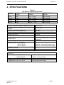
1
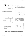
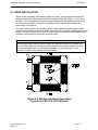
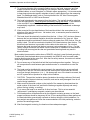
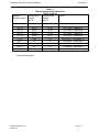
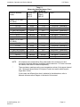
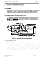
MODEL LKP SERIES (4 CHANNEL) DIRECT CURRENT METERING SYSTEMS Installation, Operation and Service Instructions Manual Item No. 041610 Rev. J DynAmp, LLC 3735 Gantz Road Grove City, Ohio 43123 USA Phone +1 614.871.6900 Fax +1 614.871.6910 www.dynamp.com [email protected] Installation, Operation and Service Manual LKP Series This Page is Intentionally Blank © 2010 DynAmp, LLC 041610 J Page ii Installation, Operation and Service Manual LKP Series DynAmp, LLC WARRANTY Items and components manufactured by Seller for permanent installation are warranted for two (2) years from the date of shipment. Items and components manufactured by Seller for portable and temporary use in more than one location are warranted to be free from defects in material and workmanship for a period of eighteen (18) months from the date of shipment. Items and components not manufactured and resold by Seller are warranted by their manufacturer. Warranty repair shall be, at DynAmp’s option, in the form of repair or replacement of the defective items or components. Concerning warranty repairs, DynAmp will be responsible for DynAmp provided time, material and transportation costs (shipping or travel). Actual method of warranty repair / correction will be determined by DynAmp at DynAmp’s sole option. Such warranty repair shall constitute a fulfillment of all DynAmp, LLC liabilities in respect to said items and components. In no event shall DynAmp, LLC be liable for consequential damages. Information in this document is subject to change without notice. © 1997, 2000, 2002, 2003, 2004, 2006, 2008, 2010 DynAmp, LLC. All rights reserved. Reproduction for purposes other than operation and service without written permission of DynAmp, LLC is strictly forbidden. This manual includes detailed drawings, installation, operation, service and maintenance. Users should evaluate the information in the manual and their particular application. DynAmp assumes no liability for any incidental, indirect, or consequential damages arising from the use of this documentation. While all information presented is believed to be reliable and in accordance with accepted engineering practices, DynAmp makes no warranties as to the completeness of the information. All trademarks used in association with LKP are trademarks of DynAmp, LLC. © 2010 DynAmp, LLC 041610 J Page iii Installation, Operation and Service Manual LKP Series This Page is Intentionally Blank © 2010 DynAmp, LLC 041610 J Page iv Installation, Operation and Service Manual LKP Series The LKP Series (4 Channel) includes the LKP-6, LKP-12, LKP-15, and LKP-30 meter units. These meter units conform to the latest European directives and standards concerning safety and electromagnetic compatibility. Application of Council Directive(s): 73/23/EEC, 89/336/EEC and 93/68/EEC. Standards to which conformity is declared: EN50081-2 utilizing method EN55011: Radiated and Conducted Emissions for Heavy Industrial Environments, Class A. EN50082-2: Radiated and Conducted Immunity Tests for Heavy Industrial Environments. Safety Standards: EN 61010-1: Safety Requirements for Electrical Equipment for Measurement, Control, and Laboratory Use. Note According to EN 50082, the manufacturer must state the degradation of performance level acceptable during immunity tests. Unless other wise noted in the manual or data sheet, DynAmp limits degradation during immunity tests for this equipment to < 0.5% FS for A-criterion tests. © 2010 DynAmp, LLC 041610 J Page v Installation, Operation and Service Manual LKP Series This Page is Intentionally Blank © 2010 DynAmp, LLC 041610 J Page vi Installation, Operation and Service Manual LKP Series Hazard Warning! All installation, maintenance and service must be performed by qualified technicians who are familiar with the warnings and instructions of this manual. Disconnect power to the system before servicing or replacing fuses. GENERAL Use of the equipment in a manner not specified by the manufacturer can impair the protection provided within. DynAmp does not assume liability for the customer’s failure to comply with the rules and requirements provided in this manual. This equipment is designed to be connected to hazardous electric voltages. Ignoring the installation precautions and warnings can result in severe personal injury or equipment damage. HAZARDOUS To avoid the risk of electrical shock or fire, the safety instructions and guidelines in this manual must be followed. The electrical specifications must not be exceeded and the unit must be installed according to directions provided. VOLTAGE This equipment is intended for indoor use only. It should be mounted in a wellventilated area, away from high heat, dust, and corrosive atmosphere. The ambient temperature must not exceed 55°C. INSTALLATION For mounting considerations that fall outside the recommended specifications provided in this manual, the factory should be contacted for approval. This unit is rated for installation category III and pollution degree 2. Symbol Identification: General definitions of safety symbols used on equipment and manual. Caution/Warning: Refer to accompanying documents for instructions. The CE mark proves the compliance of the equipment with the requirements of the directives. © 2010 DynAmp, LLC 041610 J Page vii Installation, Operation and Service Manual LKP Series This Page is Intentionally Blank © 2010 DynAmp, LLC 041610 J Page viii Installation, Operation and Service Manual LKP Series DynAmp, LLC Customer Support For further assistance, contact DynAmp Customer Support at: Americas: Telephone: +1 614.871.6900 Fax: +1 614.871.6910 8:00 AM to 5:00 PM USA Eastern Time From first Sunday in November to second Sunday in March – 13:00 GMT to 22:00 GMT From second Sunday in March to first Sunday in November – 12:00 GMT to 21:00 GMT Europe: Telephone: +41 22.706.1446 Fax: +41 22.706.1311 8:30 AM to 5:00 PM Central European Time From last Sunday in October to last Sunday in March – 7:30 GMT to 16:00 GMT From last Sunday in March to last Sunday in October – 6:30 GMT to 15:00 GMT After Hours Critical Service Emergency: Telephone: +1 614.871.6906 5:00 PM to 8:00 AM USA Eastern Time From first Sunday in November to second Sunday in March – 22:00 GMT to 13:00 GMT From second Sunday in March to first Sunday in November – 21:00 GMT to 12:00 GMT Central e-mail: [email protected] DynAmp web: www.dynamp.com © 2010 DynAmp, LLC 041610 J Page ix Installation, Operation and Service Manual LKP Series This Page is Intentionally Blank © 2010 DynAmp, LLC 041610 J Page x Installation, Operation and Service Manual LKP Series REVISION PAGE Page Change all all Drawing all, Rev NEW Rev A Rev B Rev C 26, 32 13 iii, 6, 7, 9, 17 Rev D Rev E Rev F all vii, 1, 26, 28 33 all Rev G Rev H I Rev J © 2010 DynAmp, LLC 041610 J Reason For Revision Updated several drawings and system specifications Updated drawing no.: 02D108132 Warranty, Installation Considerations, Measuring Head Resistance Tables, Technical Bulletins Section, Communications, Drawing List Updated Accuracy Diagnostics & Spare Parts section Revised Table 4-1. Updated Warranty page and Installation paragraph, 4-3 Head Installation paragraph, Updated Table 3-2 & 4-3, Deleted 4-10 & 11 and Figures 4-5 & 4-6, Update to DynAmp, LLC Update fuse precautions per ECR 1304 ECO 3166 update accuracy diagnostics drawings/list PAR 10245 – Handling & Storage, ECR 1440- Calibration Intervals / New Manual Format Date 4/97 8/97 9/97 04/00 02/02 03/03 09/03 09/04 07/06 09/08 11/10 Page xi Installation, Operation and Service Manual LKP Series This Page is Intentionally Blank © 2010 DynAmp, LLC 041610 J Page xii Installation, Operation and Service Manual LKP Series TABLE OF CONTENTS Par. Title Page 1. SAFETY __________________________________________________________ 1 2. HANDLING AND STORAGE __________________________________________ 3 3. DESCRIPTION _____________________________________________________ 5 3.1 3.2 3.3 3.4 3.5 OVERVIEW ......................................................................................................................... 5 MEASURING HEAD ............................................................................................................ 5 METERING UNIT................................................................................................................. 5 CABLE ................................................................................................................................. 5 ELECTRICAL ...................................................................................................................... 5 4. SPECIFICATIONS __________________________________________________ 7 5. INSTALLATION ____________________________________________________ 9 5.1 5.2 5.3 5.4 5.5 5.6 5.7 5.8 5.9 HANDLING PRECAUTIONS ................................................................................................ 9 MAGNETIC CONSIDERATIONS: MEASURING HEAD ....................................................... 9 HEAD INSTALLATION ...................................................................................................... 11 INSTALLATION CONSIDERATIONS ................................................................................ 12 INSTALLATION PRECAUTIONS (LIVE BUS) .................................................................... 14 COMPLETING THE HEAD INSTALLATION ...................................................................... 14 METERING UNIT INSTALLATION..................................................................................... 17 METERING UNIT WIRING ................................................................................................ 17 MAGNETIC CENTERING .................................................................................................. 18 6. THEORY OF OPERATION ___________________________________________ 21 6.1 GENERAL .......................................................................................................................... 21 6.2 MAGNETIC SENSOR (NULL DETECTOR) ....................................................................... 21 6.3 MEASURING HEAD .......................................................................................................... 21 6.4 METERING UNIT............................................................................................................... 22 6.5 POWER SUPPLIES ........................................................................................................... 22 6.6 SYNC, PLL, AND RAMPS .................................................................................................. 22 6.7 ERROR AMPLIFIERS ........................................................................................................ 22 6.8 COMPARATORS AND PULSE GENERATOR ................................................................... 22 6.9 PULSE TRANSFORMER DRIVERS .................................................................................. 23 6.10 OUTPUT CIRCUIT........................................................................................................... 23 6.11 ACCURACY DIAGNOSTICS (OPTIONAL) ...................................................................... 23 7. MAINTENANCE & SPARE PARTS ____________________________________ 27 7.1 7.2 7.3 7.4 7.5 7.6 PERIODIC MAINTENANCE .............................................................................................. 27 ANNUAL MAINTENANCE ................................................................................................. 27 RECOMMENDED CALIBRATION VERIFICATION INTERVALS........................................ 28 SPARE PARTS ORDERS - ROUTINE OR EMERGENCY.................................................. 29 RECOMMENDED SPARE PARTS* .................................................................................. 29 SERVICE ASSISTANCE.................................................................................................... 30 © 2010 DynAmp, LLC 041610 J Page xiii Installation, Operation and Service Manual LKP Series 8. RELATED TECHNICAL BULLETINS ___________________________________ 31 9. DRAWINGS _______________________________________________________ 33 DRAWINGS & TABLES Figure 5.1 Figure 5.2 Figure 5.3 Figure 5.4 Figure 6.1 General Guidelines for Locating Measuring Heads ................................................. 10 Window Insulation Description Typical For LKP-15 & LKP-30 Heads .................... 11 Measuring Head Orientation. .................................................................................. 18 Magnetic Centering ................................................................................................ 19 Magnetic Null Detector Diagram ............................................................................. 21 Table 4.1 Table 4.2 Table 5.1 Table 5.1 Table 7.1 Table 8.1 Table 9.1 LKP Series 4 Channel Specifications ......................................................................... 7 Typical Error At Zero Bus Current .............................................................................. 8 Measuring Head Resistance Chart LKP-6 & LKP-12 .............................................. 15 Measuring Head Resistance Chart LKP-15 & LKP-30 ............................................. 16 Spare Parts List ....................................................................................................... 29 Technical Bulletin List .............................................................................................. 31 Drawing List ............................................................................................................. 33 © 2010 DynAmp, LLC 041610 J Page xiv Installation, Operation and Service Manual LKP Series 1. SAFETY This equipment is designed to be connected to hazardous electric voltages. Ignoring the installation precautions and warnings can result in severe personal injury or equipment damage. Also, the equipment is heavy and requires special handling procedures to ensure the safety of both personnel and equipment itself. The following are general guidelines that should be followed when installing, operation and servicing the meter unit and head. • All installation, maintenance and service must be performed by qualified technicians who are familiar with the warnings and instructions of this manual. • Always follow all local and plant safety procedures. • Make sure that the cables are disconnected from the head during installation. Replace fuses with correct type, size and value. All channel fuses are Type MDA time delay fuses 3AB style, 1/4” x 1-1/4” (6.3mm x 32mm). Refer to the servicing instructions or spare parts list for more information on replacement fuses. Do not bypass the fuses or modify the electronics. Disconnect power to the system before replacing fuses. Failure to follow these instructions will result in intermittent operation and premature failure and will void the warranty. • Service must be performed by qualified technicians only. If use of an oscilloscope becomes necessary during servicing, the scope must be floating and not grounded. The meter unit is isolated from the mains via the power transformers. If a grounded scope is used, a hazardous condition is created since current will flow through the probe to ground. • If the installation is to be made on a "live" bus, the measuring head cables must be disconnected from the head. A condition hazardous to the measuring head and any person handling un-insulated cable-lead terminals will result if metal parts of the head contact the bus, or sudden changes in the bus current occur. • Bus current must be zero when taking resistance measurements. • Use a wire and fuse (slow-blow) size adequate for the maximum burden of 20 VA/kA of measured current. The wire should have an insulation rating of 1000Vac and 80-105° C temperature rating. • Units are not intrinsically safe. Do not place in explosive atmospheres • Do not place in the rain, or under water, or submerge any part of the head or meter unit. The measuring heads are splash proof but are not waterproof. • The heads are supplied with connector covers that must be used whenever the head cables are disconnected from the head. The covers are necessary to prevent dust and water from entering the heads. The covers also prevent fingers from contacting the connector pins during installation, which can carry hazardous voltages if the head is installed on a live bus. • The surface on which the head is mounted must be sound and capable of supporting the head. Fasteners used must be capable of supporting the weight of the head. • Measuring head should be electrically isolated from the bus bars. A ¼” (6mm) minimum distance between the bus and window insulation should be maintained. This will insure electrical isolation of the head structure from the bus. The head itself is grounded via the cables to the meter unit. • Use of the equipment in a manner not specified by the manufacturer can impair the protection provided within. © 2010 DynAmp, LLC 041610 J Page 1 Installation, Operation and Service Manual LKP Series DynAmp does not assume liability for the customer’s failure to comply with the rules and requirements provided in this manual. © 2010 DynAmp, LLC 041610 J Page 2 Installation, Operation and Service Manual LKP Series 2. HANDLING AND STORAGE DynAmp products are engineered and manufactured for use in industrial environments. However, they contain sensitive electronic and mechanical components which may be damaged and fail if not handled and stored properly. All products must be handled and stored with the same care as any precision measurement instrument. Severe bumps or jolts may damage internal parts and cause malfunction or premature failure. DynAmp products are designed and assembled with conformal coating, shock mounting, and environmental seals, when appropriate or when specified. However, this protection requires that the product must be properly installed and operational before the protection is fully functional. Therefore, adequate protection from humidity, shock, and temperature must be provided during handling and storage prior to installation. The handling and storage of equipment must be sufficient to meet the storage temperature and humidity specifications of the product and to prevent any condensation or contact with water or any other liquid. The storage location and container or crate must provide adequate protection from precipitation (rain, snow, ice) and direct water contact. Adequate shelter must be provided to prevent the accumulation of precipitation (rain, snow, ice) and water which can lead to the deterioration or failure of shipping containers or crates and cause water ingress. Storage in coastal or industrial areas subject to salt-laden or corrosive air or areas of wind-driven sand or other abrasive dust must be adequate to prevent the deterioration or failure of shipping containers or crates and cause ingress. Frequent inspection of storage areas and storage containers or crates is required to ensure proper storage conditions are being maintained. If the shipping container or crate is opened and/or the equipment is removed for inspection prior to installation, the equipment must be repackaged in the original undamaged container or crate in the same manner as it was shipped to prevent environmental damage or placed in a storage location that meets the required environmental and storage conditions. General product storage temperature and humidity requirements: Storage Temperature: -40 to 70°C -40 to 158°F Storage Humidity: 85%, non-condensing DynAmp, LLC does not assume liability for the customer’s failure to comply with handling and storage requirements. For further assistance, contact DynAmp customer support. © 2010 DynAmp, LLC 041610 J Page 3 Installation, Operation and Service Manual LKP Series This Page is Intentionally Blank © 2010 DynAmp, LLC 041610 J Page 4 Installation, Operation and Service Manual LKP Series 3. DESCRIPTION 3.1 OVERVIEW The DynAmp, LLC LKP Series 4 Channel is a system for accurately measuring direct current in a bus. Each model of the LKP Series 4 Channel consists of a two-piece measuring head, a metering unit, and one or two multi-conductor cable depending on the model. 3.2 MEASURING HEAD A magnetic core encircles the bus passing through the center of the measuring head. Magnetic null detectors are mounted in air gaps around the core. Each null detector is flanked by coils located on the magnetic core. The housing material for the LKP-6 and LKP-12 models is a tough plastic with a fiberglass fill. The larger LKP-15, LKP-30 heads are constructed of cast aluminum with a tough finish, insulation from the bus being provided by a 3/8 in (9.5 mm). layer of high grade epoxy. The head halves are easily joined around the bus by use of 8 bolts. Electrical connections for LKP-15, LKP-30 models are made through two multi-conductor cables connected to each half of the head. On LKP-6 and LKP-12 models, individual conductors from each half of the head are brought out to an external terminal block, which in turn is connected to the metering unit via a single cable. All wires from the head are color coded and clearly marked according to the interconnection diagrams supplied with this manual. 3.3 METERING UNIT The solid-state components of the metering unit are mounted on a heavy aluminum base plate and are protected by an aluminum cover. The enclosure has a rating of IP20, with an available IP54 enclosure option. Electrical connections from the control board and power board are brought out to a terminal block which serves as a tie point for the measuring head cable, output circuit, and ac input power. The metering unit provides output terminals that can provide the customer a voltage signal proportional to the measured current and/or a current output. 3.4 CABLE A standard 33-foot (10 meter) interconnecting cable is supplied with each system (longer cable lengths are available - consult the factory for details). Each of the individual conductors is tagged with a numbered label corresponding to a terminal block connection, providing an easy hookup. 3.5 ELECTRICAL Four outputs are provided by the system: A current output of 1 Adc per 5 kA of bus current, at TB1-30 and TB1-29. Maximum allowable voltage drop across the terminals is 15 Vdc at the maximum current output of the bus. © 2010 DynAmp, LLC 041610 J Page 5 Installation, Operation and Service Manual LKP Series A standard voltage output at terminals TB1-32 & TB1-31. The voltage is 100mV/kA for models LKP-6 & LKP-12; and 10mV/kA for models LKP-15 & LKP-30. An additional voltage at TB1-36 & TB1-35, when an optional shunt is installed. A normally closed relay contact for accuracy diagnostics output at TB1-37 & TB1-38. This feature is only available when the accuracy diagnostics option is ordered. © 2010 DynAmp, LLC 041610 J Page 6 Installation, Operation and Service Manual LKP Series 4. SPECIFICATIONS MODEL LKP-6 LKP-12 LKP-15 LKP-30 Table 4.1 LKP Series 4 Channel Specifications MAX. FULL-SCALE MEASURING HEAD METERING UNIT RANGE* WEIGHT WEIGHT 6 kA 12 kA 15 kA 30 kA 11 lb. (5 kg) 28 lb. (13 kg) 90 lb. (41 kg) 125 lb. (57 kg) Ambient Temperature Range of Measuring Head Ambient Temperature Range of Metering unit Location Humidity (head and metering unit) AC Line Voltage at 50 or 60 Hz ±5Hz** Burden on ac Line: *** Maximum Allowable Burden of Output Circuit Linearity Error Repeatability Error Limits Measuring Head To Bus Isolation LKP-6, LKP-12 LKP-15, LKP-30 Installation Category Pollution Degree OUTPUTS Current output: LKP-6, LKP-12 LKP-15, LKP-30 Voltage output, LKP-6, LKP-12 Voltage output, LKP-15, LKP-30 © 2010 DynAmp, LLC 041610 J 55 lb. (25 kg) 55 lb. (25 kg) 62 lb. (28 kg) 62 lb. (28 kg) -20°C to 55°C -20°C to 55°C 85% max 100,120,200,240 Vac +10%, -15% 20 VA/kA 15 volts ±0.03% of full scale from 5% to 100% of bus current. ±0.02% of full scale plus zero error. 6kVac for 1 minute with 25mm air gap 12kVac for 1 minute with 25mm air gap III 2 1 A/5 kA, ±0.2% full scale 1 A/5 kA, ±0.1% full scale 100mV per kA of bus current 10mV per kA of bus current Page 7 Installation, Operation and Service Manual LKP Series Table 4.1 LKP Series 4 Channel Specifications, Continued PHYSICAL LKP Series 4 Channel Overall Dimensions, in. (mm): LKP Metering unit (all) 12 (305) x 23 (584) x 8.4 (213) LKP-6 Measuring Head 9.25 (235) x 10.25 (260.5) LKP-12 Measuring Head 14.38 (365) x 17.75 (374.6) LKP-15 Measuring Head 17.91 (455) x 18.00 (457) LKP-30 Measuring Head 23.11 (587) x 23.23 (590) Aperture Dimensions in. (mm): LKP-6 Measuring Head 4.50 (114) x 4.50 (114) LKP-12 Measuring Head 7.25 (184) x 7.25 (184) LKP-15 Measuring Head 7.87 (200) x 7.87 (200) LKP-30 Measuring Head 13.2 (335) x 13.2 (335) NOTE The measuring head window insulation rating is directly proportional to the clearance of the head to the bus. For instance, a head in direct contact with a bus will have an insulation rating of 300V (LKP-6 & LKP-12) or 6 kV (LKP-15 & LKP-30). A clearance of 1" increases the window insulation rating to 6 kV (LKP-6 & LKP-12) or 12 kV (LKP-15 & LKP-30). Thus, the greater the distance through the air between the bus and the head, the greater the insulation rating will be. Models Max. Core Set LKP-6 ±7.5 amperes LKP-12 ±12 amperes LKP-15 ±2.25 amperes LKP-30 ±4.5 amperes Table 4.2 Typical Error At Zero Bus Current * ** *** Contingent upon DynAmp, LLC computer analysis of bus system. The LKP systems are factory-set for 50 or 60 Hz, per customer order. To operate a LKP system at a different line frequency than was ordered, move jumper JP1 (located on the control board inside each module) to the desired frequency. Size any external isolation transformers for 30VA/kA to avoid overheating the transformers due to the presence of SCR generated harmonics on the input ac line. When tested at 115 Vac, less 1 V burden, 24°C ambient. Typical zero primary current errors (bus equiv.) for each model are shown in table 4.2. © 2010 DynAmp, LLC 041610 J Page 8 Installation, Operation and Service Manual LKP Series 5. INSTALLATION 5.1 HANDLING PRECAUTIONS Even though the LKP Series systems are large and rugged, they should be handled with the same care as any precision measuring instrument. Larger measuring heads are quite heavy, and adequate handling equipment must be available. Severe jolts or bumps to the head or metering unit may cause movement of internal parts, and possibly a malfunction. It also advisable to avoid supporting the head-halves by the windows insulation. The window insulation is tough, but brittle. Personnel involved in the installation should be experienced with equipment of similar size and weight. They should also be familiar with the technical terms, warnings, and instructions in this manual, and all plant safety rules, and be able to follow these. The complete system should be inspected for shipping damage at the earliest opportunity. Visible damage must be reported to the carrier immediately. Concealed damage (not evident until the system is operated) must be reported to DynAmp, LLC immediately. 5.2 MAGNETIC CONSIDERATIONS: MEASURING HEAD The LKP Series 4 metering systems are designed and built for accuracy, stability, and reliability. However, these factors may be adversely affected by the arbitrary location of the measuring head without regard for magnetic fields. Secondary magnetic fields emanating from angled sections of the bus being monitored or from other nearby buses may cause overheating. Currents from other buses produce magnetic fields, which can sometimes cause zero offsets and errors at low current levels. To guard against these problems, you can have a computer analysis of your bus system made, or you can follow the guidelines presented in this section. FREE BUS ANALYSIS The general guidelines below should be applied only when a detailed analysis of your bus system is not available. DynAmp, LLC will perform one detailed computer analysis of the proposed location of the measuring heads within your bus system at no charge. Generally, this is done before or at the time the unit is ordered. In this way you are assured that your LKP Series 4 Channel system will function properly. Whenever possible, the head should be installed on the longest straight run of the bus that is available in an area free of other bus structures. General guidelines requiring consideration when installing a measuring head are shown in figure 5.1 (guidelines illustrated are to be considered as the minimum required distances). If the proposed head location can be physically described by more than one of the diagrams (figure 5.1), a bus analysis should be performed. For the guidelines of figure 5.1 to apply, the bus height-to-width ratio should equal the head aperture height-to-width ratio, within ±10%. This ratio does not affect the accuracy of the measurement, but it does affect the loading of different sections of the measuring head. © 2010 DynAmp, LLC 041610 J Page 9 Installation, Operation and Service Manual LKP Series a = maximum aperture dimension The head should be a minimum distance of 2a from another bus carrying equal or less current. If the other bus carries higher current, the distance should be greater, e.g., 3a. The head should be located a minimum distance of 2a from a 90° bend in the bus. If the head is to be installed on a Usection of the bus, the distance between the parallel bus sections must be a minimum of 4a, and the head should be centered between them. If the head is to be installed on a T- section of the bus, it should be located a minimum distance of 4a from the joining point. Figure 5.1 General Guidelines for Locating Measuring Heads © 2010 DynAmp, LLC 041610 J Page 10 Installation, Operation and Service Manual LKP Series 5.3 HEAD INSTALLATION Before actually installing the measuring head on the bus, the head may be checked for damage to the head and performing a head resistance check per Table 5.1 or 5.2 first, if desired. This is accomplished by connecting the cables with the head removed from the bus. After the procedure is complete, the head should be mounted according to the instructions in this section. Check the mating faces of the measuring head. Make absolutely certain that the serial numbers of both halves of the head match; otherwise you may cause misalignment and unit failure. Use only a small brush or cloth to remove any dirt particles from the head part-line insulation, multi-conductor connector, and latch areas. NOTE When installing the measuring head, protect the window insulation from impact, and do not let the weight of the measuring head rest upon the window insulation as it can be easily damaged. Also, the interconnecting cable is of top quality, but it is not armored. Protect it from abrasion and sharp edges. Figure 5.2 Window Insulation Description Typical For LKP-15 & LKP-30 Heads © 2010 DynAmp, LLC 041610 J Page 11 Installation, Operation and Service Manual LKP Series CAUTION: The part-line insulation pieces (located on the mating surfaces of the head) are brittle and can be easily damaged if one is not careful during installation. Mount the Bottom half of the head on the floor or platform and secure it in place temporarily. An arrow indicates the direction that conventional bus current must flow through the aperture: (+ to -). Place the upper half of the measuring head over the bus. Connect the bottom half of the head to the top half using the M8 bolts (provided). Tighten the bolts until snug. Do not overtighten. Since the bolts are stainless steel, it is recommended to lubricate the bolts before installation to prevent them from sticking or seizing. A dry “Moly” type lubricant is recommended. Also, make sure that the serial number on the top half of the measuring head matches the serial number of the lower half, and that the halves go together squarely and evenly without forcing, twisting, or cocking. If for some reason the head halves do not press tightly together, do not try to force the heads closer together as it might lead to damage. Check for obstacles preventing the head from mating properly. Mounting the head backward will not damage the equipment, however, the meter will read zero. After final positioning of the head, secure the mounting feet permanently to the floor or platform. NOTE The head must be installed with current arrows in the same direction as conventional current flow in the bus. No damage will occur if the head is reversed, but the system will not produce an output. 5.4 INSTALLATION CONSIDERATIONS In general, the head can be installed vertically, horizontally, or in any intermediate orientation. The measuring head is equipped with several mounting holes that can be used to bolt the head to a wall or support frame around the bus. Alternatively, optional mounting feet can be purchased that can simplify mounting the head to a platform or wall. Also available, are bus bar mounting kits that allow the LKP-15 or LKP-30 heads to be mounted directly onto a bus bar. These kits eliminate the need to assemble any additional mounting platforms or brackets. The prime considerations in all mounting cases are as follows: Read and follow the following considerations before mounting the head. These detailed in Technical Bulletin No. 9907 titled “LKP & LKB Sensor Mounting Guidelines and Restrictions.” A. Choose a mounting location where the ambient air temperature does not exceed 55°C. The standard head is designed for indoor use only and should be kept away from high heat and corrosive atmospheres. Protect the head from direct sunlight which causes the head temperature to rise, thus limiting the upper operating range in some applications. If the head is to be installed in a harsh environment, please discuss protective measures with the factory. B. The head must be protected from water. The LKP and LKB sensor head designs rated 15 kA and higher are tested to meet IP 64 when manufactured, indicating protection from splashing water from any direction. However, this rating is not a blanket approval for simply installing it outdoors without additional water protection. The measuring heads are splash proof but are not waterproof. Classification IP 64 acknowledges that some water may penetrate the seal. Water that invades the sensor is likely to cause long-term destruction. Consequently, it is necessary to provide some rain and snow protective covering if the equipment is to be mounted outdoors or in the vicinity of a sprinkler system. © 2010 DynAmp, LLC 041610 J Page 12 Installation, Operation and Service Manual LKP Series C. To minimize distortion of the magnetic field as seen by the head, temporary and final support members should be nonmagnetic (for example, aluminum beams, struts or stranded cables, or wood, fiberglass, or Phenolic where appropriate). It is recommended to keep large structural magnetic materials at least 2 meters distant from the measuring head. For additional details, refer to Technical bulletin No. 987 titled “Ferromagnetic Materials Near LKP or LKB Current Sensors.” D. The head is designed to be supported from the bottom. The top half should be attached to an anti-tipping brace. Never suspend the head by the top half alone. If the heads are to be mounted in a position other than vertical, each half of the head should be independently supported. Additional drilling of the head is NOT authorized, as damage may result. E. When mounted, the two head halves of the head should be in the same plane so no distortion of the part line will occur. No tension, twist, or excessive pressure should be applied to the part line. F. The head should be electrically insulated from the bus. A 6mm (1/4”) minimum distance between the bus and window insulation should be maintained in dry, clean air. More separation should be maintained if the bus voltage is greater than 1000 Volts or if the air quality is bad. This will insure electrical isolation of the head structure from the bus. The aluminum head structure is grounded via the cables to the meter unit. Do not short between the head structure and the bus to prevent serious damage or injury. For that reason, always disconnect the cables from the head prior to installation or maintenance. Touching both an energized bus bar and grounded measuring head may result in electrical shock. Most models interconnection cables have a GRN/YEL wire that is used for head grounding. To electrically float the head above ground potential, the GRN/YEL wire from each cable must be disconnected at the meter unit. Note that for safety reasons, the meter unit cabinet should be grounded at all times. G. Do not loosen any of the bolts that hold the head casting sections together. Doing so, will compromise the seal between parts and allow water or contaminants to enter the head. H. The head must be installed with current arrows in the same direction as conventional current flow in the bus. An arrow indicates the direction that conventional bus current must flow through the aperture (+ to -). No damage will occur if the head is reversed, but an LKP system will not produce an output in this condition. I. CAUTION: The part-line insulation pieces (located on the mating surfaces of the head) contain sensitive electronic devices, are brittle, and can be easily damaged if one is not careful during installation. J. Make sure that the serial number on the top half of the measuring head matches the serial number of the lower half, and that the halves go together squarely and evenly without forcing, twisting, or cocking. K. Try to mount the head in an area free of other bus bars. This is not an essential requirement if a satisfactory magnetic centering can be achieved. L. Final head position will be determined by the magnetic centering process, so the head support members should be temporary at first. If a bus analysis has not been performed, the head should be geometrically centered on the bus during the initial installation. If a bus analysis was performed, follow the recommendations for initial positioning, and also perform the centering process. M. After final magnetic centering, the head must have adequate support. © 2010 DynAmp, LLC 041610 J Page 13 Installation, Operation and Service Manual LKP Series 5.5 INSTALLATION PRECAUTIONS (LIVE BUS) If the unit is to be installed on a live bus, the following precautionary measures must be taken before installing the measuring head: Connect the cables to the measuring head and then connect the other end to meter unit, or follow steps b and c. The measuring head cable leads from the channel feedback coils must be shorted together and isolated from all other cable leads and ground to prevent induced high voltages on the coil leads. (14, 15, 16, 17) Magnetic sensor leads must be isolated from ground and all other leads. This can best be accomplished by taping over the individual lead connections. (6, 7, 8, 9, 10, 11, 12, 13) Always follow all local and plant safety procedures. WARNING If the installation is to be made on a "live" bus, the measuring head cable leads must not contact ground or personnel. A condition hazardous to the measuring head and any person handling un-insulated cable-lead terminals will result if metal parts of the head contact the bus. 5.6 COMPLETING THE HEAD INSTALLATION With the head temporarily installed and bus current off (or the head removed from the bus for verification prior to installation), complete the following steps. For models LKP-6 and LKP-12, connect the interconnecting cable to the terminal block near the measuring head. For all other models, connect the interconnecting cable directly to the measuring head. Before connecting the other end of the interconnecting cable to the metering unit, perform the ohmmeter tests in table 5.1 or 5.2. The tests are made from the open end of the cable, looking back towards the measuring head. Record these values for future reference. NOTE You cannot get good ohmmeter readings if the head is on a live bus. The coils pick up induced voltages from any rectifier ripple. The Hall plate resistance changes in a high magnetic field. © 2010 DynAmp, LLC 041610 J Page 14 Installation, Operation and Service Manual Measure Between Leads: 14 & 18 15 & 18 16 & 19 17 & 19 4 &5 6&7 8&9 10 & 11 12 & 13 LKP Series Table 5.1 Measuring Head Resistance Chart LKP-6 & LKP-12 Desired Value Desired Value Circuit (Ohms) (Ohms) LKP-6 LKP-12 60-65 60-65 60-65 60-65 9-12 3-6 3-6 3-6 3-6 28-33 28-33 28-33 28-33 9-12 3-6 3-6 3-6 3-6 Coil Circuit - Channel #1 Coil Circuit - Channel #2 Coil Circuit - Channel #3 Coil Circuit - Channel #4 Hall Current - Channels # 1-4 Hall Signal - Channel #1 Hall Signal - Channel #2 Hall Signal - Channel #3 Hall Signal - Channel #4 -Continued next page- © 2010 DynAmp, LLC 041610 J Page 15 Installation, Operation and Service Manual Measure Between Leads: CABLE TO “A” HALF OF HEAD 14 & 18 15 & 19 16 & 20 4 (BLK) & 5 (W/BLK) 4 (BLU) & 5 (W/BLU) 6&7 8&9 CABLE TO “B” HALF OF HEAD 16 & 20 17 & 21 14 & 18 4 (BLK) & 5 (W/BLK) 4 (BLU) & 5 (W/BLU) 10 & 11 12 & 13 LKP Series Table 5.1 Measuring Head Resistance Chart LKP-15 & LKP-30 Desired Value Desired Value Circuit (Ohms) (Ohms) LKP-15 LKP-30 46-50 23-25 46-50 3-4 k 3-4 k 240-550 240-550 22-26 11-13 22-26 3-4 k 3-4 k 240-550 240-550 Coil Circuit - Channel #1A Coil Circuit - Channel #2 Coil Circuit - Channel #3A Hall Current - Channels # 1 Hall Current - Channels # 2 Hall Signal - Channel #1 Hall Signal - Channel #2 46-50 23-25 46-50 3-4 k 3-4 k 240-550 240-550 22-26 11-13 22-26 3-4 k 3-4 k 240-550 240-550 Coil Circuit - Channel #3B Coil Circuit - Channel #4 Coil Circuit - Channel #1B Hall Current - Channels # 3 Hall Current - Channels # 4 Hall Signal - Channel #3 Hall Signal - Channel #4 NOTE: All resistances are measured by lifting cable leads at the metering unit and connecting ohmmeter between designated cable conductors. For meter units with two cables, each cable is measured separately. * These resistance readings are the room temperature values of the copper channel coils. Measured values can be 50% higher if head is hot and/or cable length is longer than 30 feet. If wire colors are different from what is indicated in the table above; refer to Alternate Interconnection Diagram in the back of this manual. © 2010 DynAmp, LLC 041610 J Page 16 Installation, Operation and Service Manual LKP Series 5.7 METERING UNIT INSTALLATION The location of the metering unit should be determined by the following factors: An indoor location where the ambient air temperature is within -20°C to +55°C at all times should be used. The location should be within reach of the head cable length to be routed. The location should be approximately 8 feet (2.5 meters) or more from high current bus bars. (Some installations have been made much closer to high current buses without difficulty, but the distance given is on the safe side.) Mount the metering unit on a wall, column, instrument panel, or other convenient location (refer to outline and mounting diagram in the back of the manual). NOTE The metering unit is convection-cooled, and does not need external cooling unless customer-mounted inside an enclosure. The metering unit does not contain filters, and requires a non-corrosive, relatively dust free environment. 5.8 METERING UNIT WIRING Before connecting the output circuit to TB1-29 and TB1-30, use an ohmmeter to make sure the output circuit is continuous and that the total resistance is within limits. The maximum allowable resistance is calculated by dividing the maximum output voltage (15 Vdc) by the full-scale output current of the system. For test purposes, a dc ammeter of the proper range can be used in place of the actual output circuit. Connect the head cables to the meter unit. The wires are labeled with numbers that correspond with the barrier strip numbers on the meter unit. The wire numbers should be used during hookup rather than relying on wire colors. Wire colors may vary and may also appear different under various lighting conditions. Remove the line filter canister cover mounted on the side of the metering unit to expose the line filter and terminal block. Connect ac line power to the terminals as follows: ground to terminal 1; phase to terminal 2; and neutral to terminal 3. A switch and main fuse are provided as part of the metering unit protection. Caution: The filter canister cover should remain on the unit during operation since supply voltage to the filter is unswitched and live voltage is present at all times. Apply 120 Vac line power and read the current through the test ammeter. The ratio between bus current and the output current is 5000:1. If a test ammeter is not used, read the current indicator across the output resistor of the output circuit. With the system operating in the final configuration (output circuit connected), measure the four channel voltages using a high quality voltmeter on the 0-50 Vdc scale. Connect the negative lead to TB1-30. Connect the positive lead to terminals TB1-14 (channel 1), TB1-15 (channel 2), TB1-16 (channel 3), and TB1-17 (channel 4). © 2010 DynAmp, LLC 041610 J Page 17 Installation, Operation and Service Manual LKP Series Read and record the voltage drop across the external burden circuit, TB1-30 (+) and TB1-29 (-). This should be no more than 15 volts when all systems are at maximum operating levels. Adjust the position of the measuring head on the bus so that channel voltages on opposite sides are approximately equal. Move the head horizontally and observe the voltage on channels 1 and 3. Select the position offering the best balance. Move the measuring head vertically and observe voltage on channels 2 and 4. Record these voltages for future reference. This process is called "electrical centering". These voltages may shift as the feedback coils change temperature. Figure 5.3 Measuring Head Orientation. The installation procedure outlined above insures proper operation of the system, and provides data in the form of resistance and voltage measurements that will serve as reference if a malfunction should develop at a later date. Bus current (conventional current not electron flow) must flow into rear face which is identified by red dots on LKP-6 and LKP-12 heads. Current direction arrows on LKP-15 and LKP-30 heads identify bus current direction. Channel No. 1 is always located on cable exit side. Channel numbers progress clockwise as viewed from front face (conventional current flow is toward the viewer). 5.9 MAGNETIC CENTERING The distribution of load (i.e., heat), among the various channels will be optimized if the head is magnetically centered. This is a process of equalizing certain channel voltages by positioning the head on the bus bar. In essence, the channel voltages from opposite sides of the head are compared and the side having the lower voltage is moved toward the bus. Using the LKP-12 as an example (refer to figure 5.4), the voltages of channels 1 and 3 are compared and the voltages of 2 and 4 compared. If the voltages are measured as shown, then the head is to be moved as indicated until the best balance at opposite sides is © 2010 DynAmp, LLC 041610 J Page 18 Installation, Operation and Service Manual LKP Series obtained. The final head position may yield voltages of 19 V at channels 1 and 3, and perhaps 13 V at channels 2 and 4. The channel voltages depend on several factors, such as total bus current, bus shape, proximity to other bus bars, and channel coil resistance. In practice, it may prove impossible to obtain full-equalized channel voltages because of a severe magnetic environment or lack of space for moving the head. In this case, the best position should be found; then all channels must be checked to see that all are within the limits of +3 V to +30 V (+3 V to 25V for LKP-12). If these limits are exceeded, another location should be selected. If other locations are not available, consult the factory regarding forced air cooling of the overloaded channels, or replacing the system with a larger unit. Figure 5.4 Magnetic Centering © 2010 DynAmp, LLC 041610 J Page 19 Installation, Operation and Service Manual LKP Series Table 5.2. Form For Recording Channel Voltage Measurements The following table is for the customer's convenience in keeping accurate records on his unit's performance. If the channel voltages are measured and recorded at least two hours after the LKP system is energized having been properly "centered" electrically, the information may prove valuable in the event of any future malfunction. It is a good idea to take an additional set of readings at the hottest time of the year, especially if the equipment is exposed to outdoor temperatures; space is provided for the recording of three sets of readings. NOTE: Although the channel voltages may vary widely with temperature extremes, the accuracy will remain unaffected so long as each channel voltage falls within the limits of +3 V to +30 Vdc (+3 V to 25 V for LKP-12). Channel voltages are measured between terminals at the metering unit terminal block with the LKP in service on an energized bus. INSTRUCTIONS 1. Measure between TB1-30 and the terminal corresponding to each channel (TB1-14 for channel 1). 2. Record the channel measurements for every channel (make additional copies of this form as needed). 3. Supply the information called for below. CHANNEL VOLTAGES All channel voltages are taken with the negative lead on terminal TB1-30, and the positive lead on the corresponding terminal shown below. READINGS Date/ Temperature TERMINAL NO. CHANNEL NO. 1 2 3 TB1-14 1 TB1-15 2 TB1-16 3 TB1-17 4 [ ] LOOP BURDEN (TB1-29): [ ] LINE VOLTAGE: [ ] BUS CURRENT (kA): Serial number of meter unit: ________________________ NOTE: The channel voltages should be between +3 and +30 Vdc (+3 V to 25 V for LKP-12). © 2010 DynAmp, LLC 041610 J Page 20 Installation, Operation and Service Manual LKP Series 6. THEORY OF OPERATION 6.1 GENERAL Knowledge of the LKP Series 4 Channel theory of operation is essential for efficient product familiarization. In figure 6.1, a portion of the measuring head is shown to illustrate the magnetic-null principle used in all LKP Series 4 Channel current measuring-equipment. 6.2 MAGNETIC SENSOR (NULL DETECTOR) The magnetic sensor produces a voltage output proportional to the difference between the bus field and the feedback field. The sensor output is amplified and is returned to the magnetic circuit in the form of feedback current. This current is passed through 5000 turns to produce the feedback field. Figure 6.1 Magnetic Null Detector Diagram 6.3 MEASURING HEAD The measuring head contains many magnetic sensors and feedback coils. Each set of sensors and the adjacent coils plus the associated amplifying section of the metering unit is termed a channel. Each channel responds nearly independently of the other channels to null the bus field in its own section of magnetic core. However, after passing through their respective coil groups, all channel currents are summed to produce the output current. This current, which is always in the ratio of 1 A to 5000 A of bus current, is passed through shunts to develop voltages for the proportional outputs. The output current itself is also available at the output terminals, which are jumpered if not used. © 2010 DynAmp, LLC 041610 J Page 21 Installation, Operation and Service Manual LKP Series 6.4 METERING UNIT Although the metering unit contains only an isolation transformer and two circuit boards, it is comprised of several sub-circuits. Each of these circuits is described in the remaining paragraphs. 6.5 POWER SUPPLIES There are three power supplies on the LKP Series 4 Channel metering unit, the 80 Vac supply, the -5 Vdc (-12 Vdc for LKP-15 & 30) supply and the ±15 Vdc supply. The 80 Vac power supply powers the SCR bridge. The ±15 Vdc power supply powers only the on-board circuitry. The -5 (or -12Vdc) supply powers the Hall devices in the measuring head. 6.6 SYNC, PLL, AND RAMPS The metering unit employs phase locked loop circuitry for synchronization of the firing pulses of the SCRs. This particularly is an advantage when there is a high noise level present on the line voltage. The PLL circuitry consists of U101, U102, and associated circuitry (see meter unit schematic drawing). The line voltage is sensed at TP-4. It is then filtered and sent to U112 to be converted into a square wave, and then to the PLL circuitry. The output of the PLL is a squarewave and is present at TP-2. This signal is sent to U104, U105, and RP101, which constitutes the ramp generator. The ramp generator output consists of two downward sloping ramps, each 180 degrees in phase from one another. Both ramps are sent to the quad comparators (U110 and U111), which are used to generate the firing pulses for the SCRs. 6.7 ERROR AMPLIFIERS The error amplifier circuitry consists of U106 through U109 and associated circuitry. The error amplifiers serve two purposes, to amplify the Hall error signal and to filter it before sending it to the comparators. 6.8 COMPARATORS AND PULSE GENERATOR The comparators consist of U110 and U111. They compare the amplified/filtered output of the error amplifiers to the two ramps generated by PLL and ramp generators. Two squarewaves are generated at the output of these comparators, one for the positive half cycle and one for the negative half, (pins 1 and 2 of U110 for channel #1). One square wave will be used to trigger an SCR on the positive half of the waveform, and the other will be used for the other half cycle. Since these squarewaves are too long in duration, they can not be used directly to drive the pulse transformer drivers. The comparator output is "ANDed" (the mathematical product of a logic AND gate) with several pulses generated by the PLL. The output, (pins 3 and 4 on U113 for channel #1) will be a pulse train which will be used to drive the pulse transformer drivers. Pulse train triggering is an advantage when noise on the line turns off an SCR. The SCR is re-triggered allowing a minimum off time. Since these pulses are fixed and do not move, if they alone are used to drive the SCRs, the output would © 2010 DynAmp, LLC 041610 J Page 22 Installation, Operation and Service Manual LKP Series be very jumpy. The pulse train is smoothed by also ANDing the comparator with an integrated output of itself to give the output pulse train infinite resolution. 6.9 PULSE TRANSFORMER DRIVERS The pulse transformer drivers consist of U203, U204, and associated circuitry. A pulse train signal is sent into the drivers (pin 2 and 1 of U203 for channel #1). These drivers are open collector outputs, which drive the pulse transformers (T203A and T203B for channel 1). The secondary of the pulse transformer develops a current pulse which drives the associated SCRs (SCR pack #1 for channel #1). 6.10 OUTPUT CIRCUIT Two outputs are provided on all LKP Series 4 Channel systems. These are: 1. Voltage Output: i. (Models LKP-6 and LKP-12): A voltage output of 100 mV per kiloAmpere of bus current, developed by a 0.5 ohm shunt at TB1-31 and TB1-32. ii. (Models LKP-15 and LKP-30): A voltage output of 10 mV per kiloAmpere of bus current, developed by a 0.05 ohm shunt at TB1-31 and TB1-32. 2. Current Output: i. LKP Series 4 Channel systems provide a dc current output, which has a 5000:1 relationship with bus current. The output circuit must be low impedance, and is connected to terminals TB1-30 (positive) and TB1-29 (negative) of the metering unit. ii. Circuit impedance is calculated by dividing the burden voltage by the full-scale output current of the measuring system. For example, a 10 kA metering system has a full scale output current of 2 amperes (10 kA/5,000 turns), and the maximum impedance of the output circuit would be 7.5 ohms (15 V/2 A). For a 30 kA system, the output current of the output circuit would be 6 amperes and the maximum load would be 2.5 ohms. An optional meter provides direct digital readout, in kiloAmperes of bus current. This meter requires 120 Vac input power, and is connected to TB1-34 and TB1-33. Burden resistors inserted in series with the output circuit should be selected with care. The wattage rating should be at least two times higher than the calculated power dissipation. The burden resistor should have a low temperature coefficient (25 ppm or better). The maximum burden across the output circuit should not exceed 15 volts. 6.11 ACCURACY DIAGNOSTICS (OPTIONAL) “ACCURACY DIAGNOSTICS” (AD) is a system that assures the user that most internal circuits are operating properly and it is also a diagnostic tool. It is made up of a number of circuits, monitoring conditions of many of the critical components, circuits and connections within the current monitoring system. The AD subsystem provides relay contacts for the user to connect to his remote warning indicator. The AD diagnostic light emitting diodes on each meter unit module indicates proper operation of associated circuits. On some larger systems, a red warning light mounted on the enclosure door provides a simple visual warning (refer to wiring diagram for this feature). © 2010 DynAmp, LLC 041610 J Page 23 Installation, Operation and Service Manual LKP Series The AD indicates the feedback circuits are functioning properly and the system’s power supplies are within specifications. More specifically, this indicates the following conditions exist: 1. All channels have a core magnetic flux null: a. All components in the circuits appear to be operating normally. b. Input fields are of the expected polarity. c. Input magnetic flux appears balanced by feedback flux. 2. Power supplies are operating within acceptable ranges. a. Mains input power is on. b. Hall plate sensor power supply output is correct. With unidirectional LKP measurement systems, it is possible that the AD circuits will give a warning indication when the system is operated at low rectifier current level, even though all circuits and components are functioning properly. This warning at low levels is most likely to occur if the metering system is associated with one of several rectifiers in the area. The AD outputs indicate the present condition, having only a short time delay from an instantaneous condition. Although the AD does not monitor every possible error condition, it is an effective means of giving the user continual assurance of signal reliability. A. If the “Diagnostics Relay” is O.K. and the green LED indicators are all on: Continue operating normally. B. If the “Diagnostics Relay” indicates a warning and one or more green indicators are off: This indicates there may be measurement errors. Consequently, the metering system should not be in full, automatic control of the rectifier. The AD relay contact output is not intended to be the only monitor protecting the power rectifiers. Primarily, it is expected that the customer wants to take immediate action to prevent unsafe operation. Unsafe operation could result if the metering system is in the rectifier control loop and it erroneously produces a significantly lower output than is true. This might cause the rectifier control circuit to inappropriately increase the power output, perhaps to overload levels for either the power supply or the process. So, if the metering system is in the control loop and the “Accuracy Diagnostics” indicates a potential problem, the following actions are recommended: FIRSTLock out control actions that could drive the rectifier output higher and SECOND-alert the operator. Basically, each module inside the metering unit has four channel LEDs and 2 power supply monitoring LEDs. The following is a description of their functionality: A. Line: This LED indicates whether the supply voltage to the meter unit falls within the specified limit of +10%, -15% of nominal. Significant changes from these values will cause this LED to turn off and trip the relay. B. Hall P.S.: This LED indicates whether the Hall plate supply voltage supply voltages fall with the specified operating limits. A failed Hall plate power supply or a line voltage out of specification will extinguish this LED and trip the relay. C. Channel LEDs: Each channel LED indicates the status of the corresponding channel to aid quick troubleshooting. An extinguished channel LED can be caused by the following: a. A blown channel fuse; b. a bad connection between the cable and the metering unit or cable and measuring head; © 2010 DynAmp, LLC 041610 J Page 24 Installation, Operation and Service Manual LKP Series c. a bad Hall device in the head; d. an open /or shorted coil in the head; e. a primary current that exceeds the dynamic measuring range of the metering unit; f. the primary current is too low to activate all channels properly; g. a strong external magnetic field causing a channel reversal. Notes on items f and g above: 1. Under certain conditions, external magnetic fields can reverse one or more channels in the head. The accuracy indicators will show an error in those channels until the bus current level rises high enough to effectively turn on all channels (2-3Vdc is the minimum reliable channel voltage). This condition can cause false alarms. For more information on this, please refer to technical bulletin TEC9908, “Resolving External Magnetic Field Errors”. 2. In some installations, when the channel voltages are balanced, the channel LEDs will remain on, even though the bus is turned down to zero. In this case, the accuracy diagnostics circuit is in an unstable condition and alarm faults, as indicated by the channel LEDs, should be ignored. Note that, in general, the metering unit’s 0.1% accuracy is only guaranteed when the primary bus current is above 5% of the full scale rating of the unit. A relay contact output is available to connect to a remote warning system. The relay is closed under normal operating conditions and opens when a fault condition occurs. The output connections are available via a connector located on the left side of the metering unit. The terminals are designated on the appropriate interconnection diagram. The terminals are used as follows: Contact Terminals Condition 37-38 37-39 Open Closed Fault condition, zero bus current*, or meter unit turned off Closed Open Normal operation * see notes above on zero bus current condition. © 2010 DynAmp, LLC 041610 J Page 25 Installation, Operation and Service Manual LKP Series This Page is Intentionally Blank © 2010 DynAmp, LLC 041610 J Page 26 Installation, Operation and Service Manual LKP Series 7. MAINTENANCE & SPARE PARTS 7.1 PERIODIC MAINTENANCE As is true with any electronic circuitry, proper maintenance will prolong the service life. DynAmp, LLC recommends the following program be performed at the recommended interval to prevent or detect damage to the LKP system and to ensure continuing highaccuracy performance. Always use appropriate measures to correct any problems found. Following the suggested maintenance schedule may assist in early diagnosis of problem(s) to minimize repairs and down time. IMPORTANT NOTE: Keep organized, accurate recorded data (forms, etc.) from each Periodic Maintenance. This information may be invaluable in troubleshooting a malfunctioning LKP system. 7.2 ANNUAL MAINTENANCE Perform the following steps at least once per year. If LKP system equipment is exposed to outdoor temperatures, DynAmp, LLC recommends these steps be performed during the hottest time of the year. The following procedures should be performed at the recommended interval to prevent or detect damage to the LKP system and to ensure continuing high-accuracy performance. Use appropriate measures to correct any problems found. A.) Repeat voltage measurements given in "Magnetic Centering" procedure to ensure that no significant change has occurred from the data recorded at startup. A large change in the amplifier output voltage of a given channel (compared to other channels) may indicate trouble in the channel. If all channels change proportionally, then that might indicate a change in the bus current. A lesser, but significant, change in a voltage measurement should be corrected by re-centering the head. Remember that channel voltages will vary slightly depending on the ambient temperature of the head. B.) Measure and record the Hall device dc power supply voltage. C.) Visually inspect measuring head and interconnection cable for evidence of severe overheating or excessive corrosion. Record any suspect conditions. D.) Inspect and touch-up the seals between the window insulation and the aluminum frame of the head. Reseal as necessary. E.) Inspect & replace if required the gasket between the cable connector and the mating head connector. F.) Inspect the condition of the pins and sockets and clean out any corrosion. G.) Visually inspect metering unit and signal converter(s) for evidence of severe overheating, or excessive corrosion. Record any suspect conditions and take appropriate action. H.) Inspect all bolts on the head and torque any that might have come loose. Observe proper torquing techniques and specs carefully. © 2010 DynAmp, LLC 041610 J Page 27 Installation, Operation and Service Manual LKP Series I.) Clean the following items: 1.) Cables and external surfaces of measuring head and metering unit: Clean as necessary; remove any oil or grease with a mild detergent or cleaner solvent. Do not use strong chemical solvents as they may damage the cables or erase the silkscreening from the metering unit. 2.) Metering unit interior (should only be performed after disconnecting power to the metering unit): Dust and dirt can be removed by gently vacuum cleaning the unit. Be careful not damage the internal shunt. Solvents should never be used on any of the PC boards. The boards are coated with a protective conformal coating that can be stripped away by certain solvents. J.) Check the electrolytic filter capacitors for seals that have been popped (degassed) or are leaking electrolytic fluid. Replace if necessary. K.) If the unit is equipped with a cooling fan and filter, then the filter should be cleaned or replaced according to the manufacturer instructions. CAUTION To avoid the risk of shock and electrocution, always disconnect the AC power and head cables from the head before performing any cleaning or service operation on the metering unit. Disconnect power to the system before servicing or replacing fuses. 7.3 RECOMMENDED CALIBRATION VERIFICATION INTERVALS DynAmp does not specify required intervals of calibration for its products. The end user of the product is responsible for identifying the appropriate interval between calibrations. The intervals should be determined based on the following factors: • Requirements of a Quality Management System • Accuracy and permissible limits of errors • Purpose and usage • Experience with similar products • Manufacturer's recommendations • Stability of the product • Past history • Other characteristics of the product Reference: "ISO/IEC 17025:2005, General requirements for the competence of testing and calibration laboratories" and Laboratory Accreditation Bureau "Guidance for Documenting and Implementing ISO/IEC 17025:2005 and Laboratory Guidance." As a guideline, DynAmp recommends a 24-month interval of calibration for all permanently installed products and a 12-month interval of calibration for all products used in portable applications. © 2010 DynAmp, LLC 041610 J Page 28 Installation, Operation and Service Manual LKP Series 7.4 SPARE PARTS ORDERS - ROUTINE OR EMERGENCY Requests for spare parts should be directed to "Service" at DynAmp, LLC during normal hours. When contacting us, please present as much information as possible, such as the related equipment Model and Serial Numbers (available on the equipment tag); the required part name; its DynAmp, LLC item number (and other identifying or vendor number(s); and your time needs. An approved Purchase Order Number should be given with your order. 7.5 RECOMMENDED SPARE PARTS* The following table lists the minimum recommended quantities* for spare parts for the LKP Series 4 Channel. As spares are used, replacements should be ordered. Since continuous operation of high-current measurement systems is usually critical, stocking spare parts should be given high priority. The LKP-15 & LKP-30 measuring heads require special repair procedures and materials. However, the heads are very reliable and should require little or no repair over its service life. Please refer to the nearest authorized DynAmp service center for information on repairs. Table 7.1 Spare Parts List DESCRIPTION ITE Q Metering Unit Kit, Spare Parts, LKP-6 Kit, Spare Parts, LKP-12 Kit, Spare Parts, LKP-15 Kit, Spare Parts, LKP-30 Spare Parts Kit includes Module and Fuses as one Module, 4 Channel, LKP-6 & 12 Module, 4 Channel, LKP-15 & 30 **Fuses, LKP-6 (main fuse, 2 Amp) (5 per box) **Fuses, LKP-6 (channel fuse, ½ Amp) (5 per box) **Fuses, LKP-12 (main fuse. 4 Amp) (5 per box) **Fuses, LKP-12 (channel fuse, 1 Amp) (5 per box) **Fuses, LKP-15 (main fuse, 6.25 Amp) (5 per box) **Fuses, LKP-15 (channel fuse, 2 Amp) (5 per box) **Fuses, LKP-30 (main fuse, 10 Amp) (5 per box) **Fuses, LKP-30 (channel fuse, 3 Amp) (5 per box) 437 437 437 437 1 1 1 1 439 411 261 035 125 125 125 261 179 125 1 1 1 1 1 1 1 1 1 1 Option ***Accuracy Diagnostics PC Board, LKP-6 & 12 419 1 ***Accuracy Diagnostics PC Board, LKP-15 & 30 413 1 * For one to five units, stock the quantities shown. For six or more units, a complete system (head, cable, and metering unit) should be kept on hand. ** All Fuses are Time lag MDA Style 3AB ¼” by 1 ¼” (6.3 mm x 32mm), 250 Volt *** Only required if accuracy diagnostics option is installed. Disconnect power to the system before servicing or replacing fuses. © 2010 DynAmp, LLC 041610 J Page 29 Installation, Operation and Service Manual LKP Series 7.6 SERVICE ASSISTANCE For further assistance, contact DynAmp Customer Support at: Americas: Telephone: +1 614.871.6900 Fax: +1 614.871.6910 8:00 AM to 5:00 PM USA Eastern Time From first Sunday in November to second Sunday in March – 13:00 GMT to 22:00 GMT From second Sunday in March to first Sunday in November – 12:00 GMT to 21:00 GMT Europe: Telephone: +41 22.706.1446 Fax: +41 22.706.1311 8:30 AM to 5:00 PM Central European Time From last Sunday in October to last Sunday in March – 7:30 GMT to 16:00 GMT From last Sunday in March to last Sunday in October – 6:30 GMT to 15:00 GMT After Hours Critical Service Emergency: Telephone: +1 614.871.6906 5:00 PM to 8:00 AM USA Eastern Time From first Sunday in November to second Sunday in March – 22:00 GMT to 13:00 GMT From second Sunday in March to first Sunday in November – 21:00 GMT to 12:00 GMT Central e-mail: [email protected] DynAmp web: www.dynamp.com © 2010 DynAmp, LLC 041610 J Page 30 Installation, Operation and Service Manual LKP Series 8. RELATED TECHNICAL BULLETINS The following is a list of available technical bulletins that contain relevant information in regards to high current measurements and the use of LKP systems. The technical bulletins are available upon request from DynAmp, LLC. Always consult the factory for a list of the latest technical bulletins. Table 8.1 Technical Bulletin List Number Subject Title / Description 9908 External Fields Resolving External Magnetic Field Errors (replaces TEC727) 9907 LKP/ LKB LKP and LKB Sensor Mounting Guidelines and Restrictions 9905 LKP/ LKB Recommended Calibration Intervals for LKP or LKB High Current Systems 9904 Diagnostics Self Diagnostics for DynAmp High Current Measurement systems (Accuracy Diagnostics) 987 LKP/ LKB Ferromagnetic Materials near LKP or LKB High Current Measurement Systems 749 Bus Analysis Computer Analysis of Measuring Head Locations In High Current Measurement systems 748 LKP/ LKB Guidelines for locations of LKP or LKB High Current Systems Heads on Busses 747 kWH Volt-hours times Ampere-Hours is NOT equal to Watthours 941 Bus Analysis Data required for Bus Analysis of High Current Measurement Systems © 2010 DynAmp, LLC 041610 J Page 31 Installation, Operation and Service Manual LKP Series This Page is Intentionally Blank © 2010 DynAmp, LLC 041610 J Page 32 Installation, Operation and Service Manual LKP Series 9. DRAWINGS Table 9.1 Drawing List * DRAWING TITLE NUMBER Outline and Mounting: LKP-6 Measuring Head 02C100425 Outline and Mounting: LKP-12 Measuring Head 02C100422 Outline and Mounting: LKP-15 Measuring Head 02C108019 Outline and Mounting: LKP-30 Measuring Head 02C108018 Option: TM-10 Bus Bar Mounting - LKP-15 & LKP-30 86.33.15.68 Option: Assembly, Mounting Feet LKP 15, -30, -45 02C108256 Wiring Diagram: Harness Assembly, LKP Series 4 Channel 83C108030 Assembly: Control Circuit PC Board 75A108104 Assembly: Accuracy Diagnostics 07A109083 Schematic: LKP Accuracy Diagnostic Board 05B109034 Schematic: LKP-6 & LKP-12 Measuring Heads 05C100436 Wiring Diagram: LKP Series 4 Channel 83B108123 Totalizing Diagram: LKP Series Meter Units 02C108033 Outline and Mounting: LKP Series 4 Channel Metering Unit 02D108059 Assembly: Supply & SCR Drive PC Board 75B108106 Schematic: LKP 4 Channel Metering Unit 05B108058 Interconnection Diagram: LKP-6/LKP-12 02D108060 Interconnection Diagram: LKP-15/LKP-30 * 02D108132 Interconnection Diagram: LKP-15/LKP-30 02D107903 Wiring Diagram: LKP-15 Measuring Head 83B107965 Wiring Diagram: LKP-30 Measuring Head 83B107966 No longer used on new systems. For reference only on some older systems prior to 1999. © 2010 DynAmp, LLC 041610 J Page 33


![[incr tsdb()]](http://vs1.manualzilla.com/store/data/005780303_1-7064634619abc733efac654e2a82e90d-150x150.png)