1
RETURN TO MAIN MENU
IM799-A
POWER WAVE F355i (CE)
January, 2005
For use with machines Code 10997, 11252
Safety Depends on You
Lincoln arc welding and cutting
equipment is designed and built
with safety in mind. However, your
overall safety can be increased by
proper installation ... and thoughtful operation on your part. DO
NOT INSTALL, OPERATE OR
REPAIR THIS EQUIPMENT
WITHOUT READING THIS
MANUAL AND THE SAFETY
PRECAUTIONS CONTAINED
THROUGHOUT. And, most
importantly, think before you act
and be careful.
i
55
3
EF
V
WA
R
E
W
PO
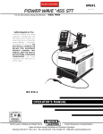
OPERATOR’S MANUAL
Copyright © 2005 Lincoln Global Inc.
• World's Leader in Welding and Cutting Products •
• Sales and Service through Subsidiaries and Distributors Worldwide •
Cleveland, Ohio 44117-1199 U.S.A. TEL: 216.481.8100 FAX: 216.486.1751 WEB SITE: www.lincolnelectric.com
i
i
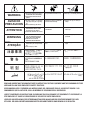
SAFETY
WARNING
CALIFORNIA PROPOSITION 65 WARNINGS
Diesel engine exhaust and some of its constituents
are known to the State of California to cause cancer, birth defects, and other reproductive harm.
The Above For Diesel Engines
The engine exhaust from this product contains
chemicals known to the State of California to cause
cancer, birth defects, or other reproductive harm.
The Above For Gasoline Engines
ARC WELDING CAN BE HAZARDOUS. PROTECT YOURSELF AND OTHERS FROM POSSIBLE SERIOUS INJURY OR DEATH.
KEEP CHILDREN AWAY. PACEMAKER WEARERS SHOULD CONSULT WITH THEIR DOCTOR BEFORE OPERATING.
Read and understand the following safety highlights. For additional safety information, it is strongly recommended that you
purchase a copy of “Safety in Welding & Cutting - ANSI Standard Z49.1” from the American Welding Society, P.O. Box
351040, Miami, Florida 33135 or CSA Standard W117.2-1974. A Free copy of “Arc Welding Safety” booklet E205 is available
from the Lincoln Electric Company, 22801 St. Clair Avenue, Cleveland, Ohio 44117-1199.
BE SURE THAT ALL INSTALLATION, OPERATION, MAINTENANCE AND REPAIR PROCEDURES ARE
PERFORMED ONLY BY QUALIFIED INDIVIDUALS.
FOR ENGINE
powered equipment.
1.h. To avoid scalding, do not remove the
radiator pressure cap when the engine is
hot.
1.a. Turn the engine off before troubleshooting and maintenance
work unless the maintenance work requires it to be running.
____________________________________________________
1.b. Operate engines in open, well-ventilated
areas or vent the engine exhaust fumes
outdoors.
____________________________________________________
1.c. Do not add the fuel near an open flame
welding arc or when the engine is running.
Stop the engine and allow it to cool before
refueling to prevent spilled fuel from vaporizing on contact with hot engine parts and
igniting. Do not spill fuel when filling tank. If
fuel is spilled, wipe it up and do not start
engine until fumes have been eliminated.
____________________________________________________
1.d. Keep all equipment safety guards, covers and devices in
position and in good repair.Keep hands, hair, clothing and
tools away from V-belts, gears, fans and all other moving
parts when starting, operating or repairing equipment.
____________________________________________________
1.e. In some cases it may be necessary to remove safety
guards to perform required maintenance. Remove
guards only when necessary and replace them when the
maintenance requiring their removal is complete.
Always use the greatest care when working near moving
parts.
___________________________________________________
1.f. Do not put your hands near the engine fan.
Do not attempt to override the governor or
idler by pushing on the throttle control rods
while the engine is running.
ELECTRIC AND
MAGNETIC FIELDS
may be dangerous
2.a. Electric current flowing through any conductor causes
localized Electric and Magnetic Fields (EMF). Welding
current creates EMF fields around welding cables and
welding machines
2.b. EMF fields may interfere with some pacemakers, and
welders having a pacemaker should consult their physician
before welding.
2.c. Exposure to EMF fields in welding may have other health
effects which are now not known.
2.d. All welders should use the following procedures in order to
minimize exposure to EMF fields from the welding circuit:
2.d.1. Route the electrode and work cables together - Secure
them with tape when possible.
2.d.2. Never coil the electrode lead around your body.
2.d.3. Do not place your body between the electrode and
work cables. If the electrode cable is on your right
side, the work cable should also be on your right side.
2.d.4. Connect the work cable to the workpiece as close as
possible to the area being welded.
___________________________________________________
1.g. To prevent accidentally starting gasoline engines while
turning the engine or welding generator during maintenance
work, disconnect the spark plug wires, distributor cap or
magneto wire as appropriate.
2.d.5. Do not work next to welding power source.
Mar ‘95
ii
ii
SAFETY
ARC RAYS can burn.
ELECTRIC SHOCK can
kill.
3.a. The electrode and work (or ground) circuits
are electrically “hot” when the welder is on.
Do not touch these “hot” parts with your bare
skin or wet clothing. Wear dry, hole-free
gloves to insulate hands.
3.b. Insulate yourself from work and ground using dry insulation.
Make certain the insulation is large enough to cover your full
area of physical contact with work and ground.
In addition to the normal safety precautions, if welding
must be performed under electrically hazardous
conditions (in damp locations or while wearing wet
clothing; on metal structures such as floors, gratings or
scaffolds; when in cramped positions such as sitting,
kneeling or lying, if there is a high risk of unavoidable or
accidental contact with the workpiece or ground) use
the following equipment:
• Semiautomatic DC Constant Voltage (Wire) Welder.
• DC Manual (Stick) Welder.
• AC Welder with Reduced Voltage Control.
3.c. In semiautomatic or automatic wire welding, the electrode,
electrode reel, welding head, nozzle or semiautomatic
welding gun are also electrically “hot”.
3.d. Always be sure the work cable makes a good electrical
connection with the metal being welded. The connection
should be as close as possible to the area being welded.
3.e. Ground the work or metal to be welded to a good electrical
(earth) ground.
3.f. Maintain the electrode holder, work clamp, welding cable and
welding machine in good, safe operating condition. Replace
damaged insulation.
3.g. Never dip the electrode in water for cooling.
3.h. Never simultaneously touch electrically “hot” parts of
electrode holders connected to two welders because voltage
between the two can be the total of the open circuit voltage
of both welders.
3.i. When working above floor level, use a safety belt to protect
yourself from a fall should you get a shock.
3.j. Also see Items 6.c. and 8.
4.a. Use a shield with the proper filter and cover
plates to protect your eyes from sparks and
the rays of the arc when welding or observing
open arc welding. Headshield and filter lens
should conform to ANSI Z87. I standards.
4.b. Use suitable clothing made from durable flame-resistant
material to protect your skin and that of your helpers from
the arc rays.
4.c. Protect other nearby personnel with suitable, non-flammable
screening and/or warn them not to watch the arc nor expose
themselves to the arc rays or to hot spatter or metal.
FUMES AND GASES
can be dangerous.
5.a. Welding may produce fumes and gases
hazardous to health. Avoid breathing these
fumes and gases.When welding, keep
your head out of the fume. Use enough
ventilation and/or exhaust at the arc to keep
fumes and gases away from the breathing zone. When
welding with electrodes which require special
ventilation such as stainless or hard facing (see
instructions on container or MSDS) or on lead or
cadmium plated steel and other metals or coatings
which produce highly toxic fumes, keep exposure as
low as possible and below Threshold Limit Values (TLV)
using local exhaust or mechanical ventilation. In
confined spaces or in some circumstances, outdoors, a
respirator may be required. Additional precautions are
also required when welding on galvanized steel.
5.b. Do not weld in locations near chlorinated hydrocarbon vapors
coming from degreasing, cleaning or spraying operations.
The heat and rays of the arc can react with solvent vapors to
form phosgene, a highly toxic gas, and other irritating products.
5.c. Shielding gases used for arc welding can displace air and
cause injury or death. Always use enough ventilation,
especially in confined areas, to insure breathing air is safe.
5.d. Read and understand the manufacturer’s instructions for this
equipment and the consumables to be used, including the
material safety data sheet (MSDS) and follow your
employer’s safety practices. MSDS forms are available from
your welding distributor or from the manufacturer.
5.e. Also see item 1.b.
Mar ‘95
iii
iii
SAFETY
WELDING SPARKS can
cause fire or explosion.
6.a. Remove fire hazards from the welding area.
If this is not possible, cover them to prevent
the welding sparks from starting a fire.
Remember that welding sparks and hot
materials from welding can easily go through small cracks
and openings to adjacent areas. Avoid welding near
hydraulic lines. Have a fire extinguisher readily available.
6.b. Where compressed gases are to be used at the job site,
special precautions should be used to prevent hazardous
situations. Refer to “Safety in Welding and Cutting” (ANSI
Standard Z49.1) and the operating information for the
equipment being used.
6.c. When not welding, make certain no part of the electrode
circuit is touching the work or ground. Accidental contact
can cause overheating and create a fire hazard.
6.d. Do not heat, cut or weld tanks, drums or containers until the
proper steps have been taken to insure that such procedures
will not cause flammable or toxic vapors from substances
inside. They can cause an explosion even though they have
been “cleaned”. For information, purchase “Recommended
Safe Practices for the Preparation for Welding and Cutting of
Containers and Piping That Have Held Hazardous
Substances”, AWS F4.1 from the American Welding Society
(see address above).
6.e. Vent hollow castings or containers before heating, cutting or
welding. They may explode.
6.f. Sparks and spatter are thrown from the welding arc. Wear oil
free protective garments such as leather gloves, heavy shirt,
cuffless trousers, high shoes and a cap over your hair. Wear
ear plugs when welding out of position or in confined places.
Always wear safety glasses with side shields when in a
welding area.
6.g. Connect the work cable to the work as close to the welding
area as practical. Work cables connected to the building
framework or other locations away from the welding area
increase the possibility of the welding current passing
through lifting chains, crane cables or other alternate circuits. This can create fire hazards or overheat lifting chains
or cables until they fail.
6.h. Also see item 1.c.
CYLINDER may explode
if damaged.
7.a. Use only compressed gas cylinders
containing the correct shielding gas for the
process used and properly operating
regulators designed for the gas and
pressure used. All hoses, fittings, etc. should be suitable for
the application and maintained in good condition.
7.b. Always keep cylinders in an upright position securely
chained to an undercarriage or fixed support.
7.c. Cylinders should be located:
• Away from areas where they may be struck or subjected to
physical damage.
• A safe distance from arc welding or cutting operations and
any other source of heat, sparks, or flame.
7.d. Never allow the electrode, electrode holder or any other
electrically “hot” parts to touch a cylinder.
7.e. Keep your head and face away from the cylinder valve outlet
when opening the cylinder valve.
7.f. Valve protection caps should always be in place and hand
tight except when the cylinder is in use or connected for
use.
7.g. Read and follow the instructions on compressed gas
cylinders, associated equipment, and CGA publication P-l,
“Precautions for Safe Handling of Compressed Gases in
Cylinders,” available from the Compressed Gas Association
1235 Jefferson Davis Highway, Arlington, VA 22202.
FOR ELECTRICALLY
powered equipment.
8.a. Turn off input power using the disconnect
switch at the fuse box before working on
the equipment.
8.b. Install equipment in accordance with the U.S. National
Electrical Code, all local codes and the manufacturer’s
recommendations.
8.c. Ground the equipment in accordance with the U.S. National
Electrical Code and the manufacturer’s recommendations.
Mar ‘95
iv
SAFETY
PRÉCAUTIONS DE SÛRETÉ
Pour votre propre protection lire et observer toutes les instructions
et les précautions de sûreté specifiques qui parraissent dans ce
manuel aussi bien que les précautions de sûreté générales suivantes:
Sûreté Pour Soudage A L’Arc
1. Protegez-vous contre la secousse électrique:
a. Les circuits à l’électrode et à la piéce sont sous tension
quand la machine à souder est en marche. Eviter toujours
tout contact entre les parties sous tension et la peau nue
ou les vétements mouillés. Porter des gants secs et sans
trous pour isoler les mains.
b. Faire trés attention de bien s’isoler de la masse quand on
soude dans des endroits humides, ou sur un plancher
metallique ou des grilles metalliques, principalement dans
les positions assis ou couché pour lesquelles une grande
partie du corps peut être en contact avec la masse.
c. Maintenir le porte-électrode, la pince de masse, le câble
de soudage et la machine à souder en bon et sûr état
defonctionnement.
d.Ne jamais plonger le porte-électrode dans l’eau pour le
refroidir.
e. Ne jamais toucher simultanément les parties sous tension
des porte-électrodes connectés à deux machines à souder
parce que la tension entre les deux pinces peut être le
total de la tension à vide des deux machines.
f. Si on utilise la machine à souder comme une source de
courant pour soudage semi-automatique, ces precautions
pour le porte-électrode s’applicuent aussi au pistolet de
soudage.
2. Dans le cas de travail au dessus du niveau du sol, se protéger
contre les chutes dans le cas ou on recoit un choc. Ne jamais
enrouler le câble-électrode autour de n’importe quelle partie
du corps.
3. Un coup d’arc peut être plus sévère qu’un coup de soliel,
donc:
a. Utiliser un bon masque avec un verre filtrant approprié
ainsi qu’un verre blanc afin de se protéger les yeux du rayonnement de l’arc et des projections quand on soude ou
quand on regarde l’arc.
b. Porter des vêtements convenables afin de protéger la
peau de soudeur et des aides contre le rayonnement de
l‘arc.
c. Protéger l’autre personnel travaillant à proximité au
soudage à l’aide d’écrans appropriés et non-inflammables.
4. Des gouttes de laitier en fusion sont émises de l’arc de
soudage. Se protéger avec des vêtements de protection libres
de l’huile, tels que les gants en cuir, chemise épaisse, pantalons sans revers, et chaussures montantes.
5. Toujours porter des lunettes de sécurité dans la zone de
soudage. Utiliser des lunettes avec écrans lateraux dans les
zones où l’on pique le laitier.
iv
6. Eloigner les matériaux inflammables ou les recouvrir afin de
prévenir tout risque d’incendie dû aux étincelles.
7. Quand on ne soude pas, poser la pince à une endroit isolé de
la masse. Un court-circuit accidental peut provoquer un
échauffement et un risque d’incendie.
8. S’assurer que la masse est connectée le plus prés possible
de la zone de travail qu’il est pratique de le faire. Si on place
la masse sur la charpente de la construction ou d’autres
endroits éloignés de la zone de travail, on augmente le risque
de voir passer le courant de soudage par les chaines de levage, câbles de grue, ou autres circuits. Cela peut provoquer
des risques d’incendie ou d’echauffement des chaines et des
câbles jusqu’à ce qu’ils se rompent.
9. Assurer une ventilation suffisante dans la zone de soudage.
Ceci est particuliérement important pour le soudage de tôles
galvanisées plombées, ou cadmiées ou tout autre métal qui
produit des fumeés toxiques.
10. Ne pas souder en présence de vapeurs de chlore provenant
d’opérations de dégraissage, nettoyage ou pistolage. La
chaleur ou les rayons de l’arc peuvent réagir avec les vapeurs
du solvant pour produire du phosgéne (gas fortement toxique)
ou autres produits irritants.
11. Pour obtenir de plus amples renseignements sur la sûreté,
voir le code “Code for safety in welding and cutting” CSA
Standard W 117.2-1974.
PRÉCAUTIONS DE SÛRETÉ POUR
LES MACHINES À SOUDER À
TRANSFORMATEUR ET À
REDRESSEUR
1. Relier à la terre le chassis du poste conformement au code de
l’électricité et aux recommendations du fabricant. Le dispositif
de montage ou la piece à souder doit être branché à une
bonne mise à la terre.
2. Autant que possible, I’installation et l’entretien du poste seront
effectués par un électricien qualifié.
3. Avant de faires des travaux à l’interieur de poste, la debrancher à l’interrupteur à la boite de fusibles.
4. Garder tous les couvercles et dispositifs de sûreté à leur
place.
Mar. ‘93
v
v
SAFETY
ELECTROMAGNETIC COMPATIBILITY (EMC)
Conformance
Products displaying the CE mark are in conformity with European Community Council Directive of 3 May
1989 on the approximation of the laws of the Member States relating to electromagnetic compatibility
(89/336/EEC). It was manufactured in conformity with a national standard that implements a harmonized
standard: EN 50 199 Electromagnetic Compatibility (EMC) Product Standard for Arc Welding Equipment. It
is for use with other Lincoln Electric equipment. It is designed for industrial and professional use.
Introduction
All electrical equipment generates small amounts of electromagnetic emission. Electrical emission may be
transmitted through power lines or radiated through space, similar to a radio transmitter. When emissions are
received by other equipment, electrical interference may result. Electrical emissions may affect many kinds of
electrical equipment; other nearby welding equipment, radio and TV reception, numerical controlled machines,
telephone systems, computers, etc. Be aware that interference may result and extra precautions may be required
when a welding power source is used in a domestic establishment.
Installation and Use
The user is responsible for installing and using the welding equipment according to the manufacturer s instructions.
If electromagnetic disturbances are detected then it shall be the responsibility of the user of the welding equipment
to resolve the situation with the technical assistance of the manufacturer. In some cases this remedial action may
be as simple as earthing (grounding) the welding circuit, see Note. In other cases it could involve constructing an
electromagnetic screen enclosing the power source and the work complete with associated input filters. In all cases
electromagnetic disturbances must be reduced to the point where they are no longer troublesome.
Note: The welding circuit may or may not be earthed for safety reasons according to national codes.
Changing the earthing arrangements should only be authorized by a person who is competent to
assess whether the changes will increase the risk of injury, e.g., by allowing parallel welding
current return paths which may damage the earth circuits of other equipment.
Assessment of Area
Before installing welding equipment the user shall make an assessment of potential electromagnetic problems in the
surrounding area. The following shall be taken into account:
a) other supply cables, control cables, signaling and telephone cables; above, below and adjacent to the
welding equipment;
b) radio and television transmitters and receivers;
c) computer and other control equipment;
d) safety critical equipment, e.g., guarding of industrial equipment;
e) the health of the people around, e.g., the use of pacemakers and hearing aids;
f) equipment used for calibration or measurement;
g) the immunity of other equipment in the environment. The user shall ensure that other equipment being
used in the environment is compatible. This may require additional protection measures;
h) the time of day that welding or other activities are to be carried out.
3-1-96H
L10093
vi
vi
SAFETY
ELECTROMAGNETIC COMPATIBILITY (EMC)
The size of the surrounding area to be considered will depend on the structure of the building and other activities
that are taking place. The surrounding area may extend beyond the boundaries of the premises.
Methods of Reducing Emissions
Mains Supply
Welding equipment should be connected to the mains supply according to the manufacturer s recommendations.
If interference occurs, it may be necessary to take additional precautions such as filtering of the mains supply.
Consideration should be given to shielding the supply cable of permanently installed welding equipment, in metallic
conduit or equivalent. Shielding should be electrically continuous throughout its length. The shielding should be
connected to the welding power source so that good electrical contact is maintained between the conduit and the
welding power source enclosure.
Maintenance of the Welding Equipment
The welding equipment should be routinely maintained according to the manufacturer s recommendations. All
access and service doors and covers should be closed and properly fastened when the welding equipment is in
operation. The welding equipment should not be modified in any way except for those changes and adjustments
covered in the manufacturers instructions. In particular, the spark gaps of arc striking and stabilizing devices should
be adjusted and maintained according to the manufacturer s recommendations.
Welding Cables
The welding cables should be kept as short as possible and should be positioned close together, running at or close
to the floor level.
Equipotential Bonding
Bonding of all metallic components in the welding installation and adjacent to it should be considered. However,
metallic components bonded to the work piece will increase the risk that the operator could receive a shock by
touching these metallic components and the electrode at the same time. The operator should be insulated from all
such bonded metallic components.
Earthing of the Workpiece
Where the workpiece is not bonded to earth for electrical safety, not connected to earth because of its size and
position, e.g., ships hull or building steelwork, a connection bonding the workpiece to earth may reduce emissions
in some, but not all instances. Care should be taken to prevent the earthing of the workpiece increasing the risk
of injury to users, or damage to other electrical equipment. Where necessary, the connection of the workpiece to
earth should be made by a direct connection to the workpiece, but in some countries where direct connection is not
permitted, the bonding should be achieved by suitable capacitance, selected according to national regulations.
Screening and Shielding
Selective screening and shielding of other cables and equipment in the surrounding area may alleviate problems of
1
interference. Screening of the entire welding installation may be considered for special applications.
1
Portions of the preceding text are contained in EN50199: "Electromagnetic Compatibility (EMC) product standard for
arc welding equipment."
3-1-96H
L10093
vii
vii
Thank You
for selecting a QUALITY product by Lincoln Electric. We want you
to take pride in operating this Lincoln Electric Company product
••• as much pride as we have in bringing this product to you!
Please Examine Carton and Equipment For Damage Immediately
When this equipment is shipped, title passes to the purchaser upon receipt by the carrier. Consequently, Claims
for material damaged in shipment must be made by the purchaser against the transportation company at the
time the shipment is received.
Please record your equipment identification information below for future reference. This information can be
found on your machine nameplate.
Product _________________________________________________________________________________
Model Number ___________________________________________________________________________
Code Number or Date Code_________________________________________________________________
Serial Number____________________________________________________________________________
Date Purchased___________________________________________________________________________
Where Purchased_________________________________________________________________________
Whenever you request replacement parts or information on this equipment, always supply the information you
have recorded above. The code number is especially important when identifying the correct replacement parts.
On-Line Product Registration
- Register your machine with Lincoln Electric either via fax or over the Internet.
• For faxing: Complete the form on the back of the warranty statement included in the literature packet
accompanying this machine and fax the form per the instructions printed on it.
• For On-Line Registration: Go to our WEB SITE at www.lincolnelectric.com. Choose “Quick Links” and then
“Product Registration”. Please complete the form and submit your registration.
Read this Operators Manual completely before attempting to use this equipment. Save this manual and keep it
handy for quick reference. Pay particular attention to the safety instructions we have provided for your protection.
The level of seriousness to be applied to each is explained below:
WARNING
This statement appears where the information must be followed exactly to avoid serious personal injury or
loss of life.
CAUTION
This statement appears where the information must be followed to avoid minor personal injury or damage to
this equipment.
viii
viii
TABLE OF CONTENTS
Page
Installation .......................................................................................................Section A
Technical Specifications - POWER WAVE 355 ....................................................A-1
Safety Precautions.................................................................................................A-2
Select Suitable Location ........................................................................................A-2
Stacking ..........................................................................................................A-2
Tilting...............................................................................................................A-2
Input and Grounding Connections ..................................................................A-2
Power Cord Connection ..................................................................................A-2
Undercarriage Mountings................................................................................A-2
Output Cables, Connections and Limitations.........................................................A-3
Negative Electrode Polarity ...................................................................................A-3
Voltage Sensing ............................................................................................A-3, A-4
Power Wave to Semi-automatic Power Feed Wire Feeder Interconnections........A-4
Control Cable Specifications..................................................................................A-4
System Description................................................................................................A-5
System Set-Up.........................................................................................A-6 thru A-8
Welding with Multiple Power Waves......................................................................A-9
I / O Receptacle Specifications............................................................................A-10
Dip Switch Settings and Locations...............................................................A-10
Control Board Dip Switch ..............................................................................A-10
________________________________________________________________________
Operation .........................................................................................................Section B
Safety Precautions.................................................................................................B-1
General Description ...............................................................................................B-1
Recommended Processes and Equipment ...........................................................B-1
Recommended Processes ..............................................................................B-1
Required Equipment .......................................................................................B-2
Limitations .......................................................................................................B-2
Duty Cycle and Time Period ...........................................................................B-2
Case Front Controls ................................................................................B-2, B-3
Nominal Procedures........................................................................................B-3
Fringe Procedures...........................................................................................B-3
Making a Weld ................................................................................................B-3
Welding Adjustment ........................................................................................B-3
Constant Voltage Welding...............................................................................B-4
Pulse Welding, Pulse on Pulse (GMAW) ........................................................B-4
Power Mode ....................................................................................................B-5
________________________________________________________________________
Accessories .....................................................................................................Section C
Optional Equipment ...............................................................................................C-1
Factory Installed..............................................................................................C-1
Field Installed..................................................................................................C-1
Compatible Lincoln Equipment
________________________________________________________________________
Maintenance ....................................................................................................Section D
Safety Precautions ................................................................................................D-1
Capacitor Discharge Procedure ............................................................................D-1
Routine Maintenance.............................................................................................D-1
Periodic Maintenance ............................................................................................D-1
Calibration Specification ........................................................................................D-1
________________________________________________________________________
Troubleshooting ..............................................................................................Section E
How to use Troubleshooting Guide .......................................................................E-1
Using the Status LED to Troubleshoot System Problems .....................................E-2
Troubleshooting Guide.............................................................................E-3 thru E-7
________________________________________________________________________
Wiring Diagram ....................................................................................Section F-1, F-2
Connection Diagram ....................................................................................Section F-3
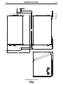
Dimension Print............................................................................................Section F-4
________________________________________________________________________
Parts Lists ................................................................................................................P432
________________________________________________________________________
A-1
A-1
INSTALLATION
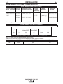
TECHNICAL SPECIFICATIONS - POWER WAVE F355i
INPUT AC VOLTAGE & DC OUTPUT
Product Ordering Input AC
Name Information Voltage
POWER
WAVE
F355i
K2260-1
K2260-2
Rated DC Output
Amps/Volts/Duty Cycle
380-415
Output
Range
(continuous)
Weight
with Cord
Dimensions
HxWxD
350A / 34V / 60%
60/50 Hz
3 Phase
AMPS
5-425
14.6” x 17.2” x 27.6”*
(371 x 437 x 701*)mm
110.0 lbs.
(50.0. kg.)
300A / 32V /100%
* Includes Mounting
Brackets
* Overall Length without Mounting Brackets, 21.06” (535mm)
POWER WAVE F355i INPUT CURRENT
Recommended Fuse Sizes Base On The U.S. National Electrical Code And Maximum Machine Outputs
Input 50/60 Hz
Voltage
Phases
380
400
415
3
3
3
Output
300Amps @
32Volts(100%)
23
22
22
350Amps @
34Volts(60%)
28
27
26
Recommended
Line Cord
Fuse size
10mm2
10mm2
10mm2
40A
40A
40A
OUTPUT CABLES, CONNECTIONS AND LIMITATIONS
Select The output cable size based upon the following chart.*
Cable sizes for Combined Length of Electrode and Work Cable (Copper) 75C rated:
CURRENT
DUTY CYCLE
LENGTH UP 200FT.(61m)
300
100%
2/0
350
60%
2/0
200-250 FT. (61-76m)
2/0
2/0
*Lincoln Electric recommends using a minimum of 2/0 welding cable for pulse welding.
POWER WAVE F355i (CE)
A-2
A-2
INSTALLATION
SAFETY PRECAUTIONS
WARNING
CAUTION
ELECTRIC SHOCK can kill.
• Turn the input power off at the disconnect switch before attempting
to connect or disconnect input
power lines, output cables or control cables
• Only qualified personnel should perform this
installation.
• Connect the green lead of the power cord to
ground per National Electrical Code.
----------------------------------------------------------------------
• Incorrect connection may result in equipment
damage.
-----------------------------------------------------------------------
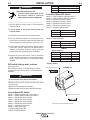
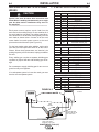
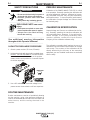
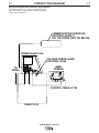
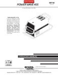
POWER CORD CONNECTION
A 7ft. (2m) power cord is provided and wired into the
machine. Follow the power cord connection instructions.
SELECT SUITABLE LOCATION
i
55
E
AV
RW
The Invertec POWER WAVE F355i will operate in
harsh environments. Even so, it is important that simple preventative measures are followed in order to
assure long life and reliable operation.
• The machine must be located where there is free circulation of clean air such that air movement in the
back, out the sides and bottom will not be restricted.
• Dirt and dust that can be drawn into the machine
should be kept to a minimum. Failure to observe
these precautions can result in excessive operating
temperatures and nuisance shutdown.
F3
WE
PO
BLACK
GREEN/YELLOW
BLUE
BROWN
Three Phase Input
Connect green lead to ground per National Electric
Code.
Connect black, red and white leads to power.
• Keep machine dry. Shelter from rain and snow. Do
not place on wet ground or in puddles.
• DO NOT MOUNT OVER COMBUSTIBLE SURFACES.
CAUTION
Where there is a combustible surface directly
under stationary or fixed electrical equipment,
that surface shall be covered with a steel plate at
least .06”(1.6mm) thick, which shall extend not
less than 5.90”(150mm) beyond the equipment on
all sides.
----------------------------------------------------------------------STACKING
POWER WAVE F355i can not be stacked.
TILTING
Place the machine directly on a secure, level surface
or on a recommended undercarriage. The machine
may topple over if this procedure is not followed.
INPUT AND GROUNDING CONNECTIONS
• Only a qualified electrician should connect the
Invertec POWER WAVE F355i. Installation should
be made in accordance with the appropriate
National Electrical Code.
POWER WAVE F355i (CE)
A-3
A-3
INSTALLATION
OUTPUT CABLES, CONNECTIONS AND
LIMITATIONS
Connect a work lead of sufficient size and length
between the proper output terminal on the power
source and the work. Be sure the connection to the
work makes tight metal-to-metal electrical contact. To
avoid interference problems with other equipment and
to achieve the best possible operation, route all cables
directly to the work or wire feeder. Avoid excessive
lengths and do not coil excess cable.
CAUTION
When using an inverter type power source like the
Power Waves, use the largest welding (electrode
and work) cables that are practical. At least 2/0
copper wire - even if the average output current
would not normally require it. When pulsing, the
pulse current can reach very high levels. Voltage
drops can become excessive, leading to poor
welding characteristics, if undersized welding
cables are used.
-----------------------------------------------------------------------Most welding applications run with the electrode being
positive (+). For those applications, connect the electrode cable between the wire feeder and the positive
(+) output Twist-Mate terminal on the power source.
Connect the other end of the electrode cable to the
wire feeder at it’s proper connection point. Be sure the
connection makes tight metal-to-metal electrical contact. The electrode cable should be sized according to
the specifications given in the output cable connections section. Connect a work lead from the negative
(-) power source output Twist-Mate terminal to the
work piece. The work piece connection must be firm
and secure, especially if pulse welding is planned.
For additional Safety information regarding the electrode and work cable set-up, See the standard "SAFETY INFORMATION" located in the front of the
Instruction Manuals.
CAUTION
Excessive voltage drops caused by poor work
piece connections often result in unsatisfactory
welding performance.
------------------------------------------------------------------------
NEGATIVE ELECTRODE POLARITY
When negative electrode polarity is required, such as
in some Innershield applications, reverse the output
connections at the power source (electrode cable to
the negative (-) Twist-Mate terminal, and work cable
to the positive (+) Twist-Mate terminal.
When operating with electrode polarity negative the
"Electrode Sense Polarity" DIP switch must be set to the
"Negative" position on the Wire Drive Feed Head PC Board.
The default setting of the switch is positive electrode polarity. Set the Negative Polarity switch on Wire Feed Head PC
board as follows:
WARNING
ELECTRIC SHOCK can kill
• Turn the input power OFF at the disconnect switch or fuse box before
working on this equipment.
• Do not touch electrically hot parts.
----------------------------------------------------------1. Turn off power to the power source at the disconnect
switch.
2. Remove the front cover from the power source.
3. The feed head PC board is on the left side of the power
source. Locate the 8-position DIP switch and look for
switch 7 of the DIP switch.(See Figure A.1)
4. Using a pencil or other small object, slide the switch to
the OFF position for positive electrode polarity.
Conversely, slide the switch to the ON position for negative electrode polarity.
5. Replace the cover and screws. The PC board will“read”
the switch at power up, and configure the work voltage
sense lead appropriately.
VOLTAGE SENSING
The best arc performance occurs when the PowerWaves
have accurate data about the arc conditions. Depending
upon the process, inductance within the electrode and work
lead cables can influence the voltage apparent at the studs
of the welder. Voltage sense leads improve the accuracy of
the arc conditions and can have a dramatic effect on performance. Sense Lead Kits (K940-10, -25 or -50) are available
for this purpose.
CAUTION
If the voltage sensing is enabled but the sense
leads are missing, improperly connected, or if the
electrode polarity switch is improperly configured,
extremely high welding outputs may occur.
-----------------------------------------------------------------------The ELECTRODE sense lead (67) is built into the control
cable, and is automatically enabled for all semi-automatic
processes. The WORK sense lead (21) connects to the
Power Wave at the four pin connector. By default the
WORK voltage is monitored at the output stud in the
POWER WAVE F355i (CE). For more information on the
WORK sense lead (21), see"Work Voltage Sensing” in the
following paragraph.
POWER WAVE F355i (CE)
A-4
A-4
INSTALLATION
Enable the voltage sense leads as follows:
TABLE A.1
Process Electrode Voltage
Work Voltage
Sensing 67 lead *
Sensing 21 lead
GMAW 67 lead required
21 lead optional
GMAW-P 67 lead required
21 lead optional
FCAW 67 lead required
21 lead optional
GTAW Voltage sense at studs Voltage sense at studs
GMAW Voltage sense at studs Voltage sense at studs
SAW
67 lead required
21 lead optional
CAC-C Voltage sense at studs Voltage sense at studs
5. Replace the wrap around and screws. The PC
board will “read” the switch at power up, and configure the work voltage sense lead appropriately.
ELECTRODE VOLTAGE SENSING
Enabling or disabling electrode voltage sensing is
automatically configured through software. The 67
electrode sense lead is internal to the cable to the
wire feeder and always connected when a wire feeder
is present.
* The electrode voltage 67 sense lead is integral to the
control cable to the wire feeder.
CAUTION
Work Voltage Sensing
The standard POWER WAVE F355i (CE)’s default is
to the work stud (work sense lead disabled).
Important: The electrode polarity must be configured on the feed head PC board. Failure to do so
may result in extremely high welding outputs.
------------------------------------------------------------------------
For processes requiring work voltage sensing, connect the (21) work voltage sense lead (K940) from the
Power Wave work sense lead receptacle to the work
piece. Attach the sense lead to the work piece as
close to the weld as practical, but not in the return current path. Enable the work voltage sensing in the
Power Wave as follows:
WARNING
ELECTRIC SHOCK can kill
• Turn the input power OFF at the
disconnect switch or fuse box
before working on this equipment.
POWER WAVE / POWER FEED WIRE
FEEDER INTERCONNECTIONS
(See Section F-2 for Connection Diagram)
Connect the control cable between the power source
and wire feeder. The wire feeder connection on the
POWER WAVE F355i (CE) is the 14-pin connector
located on the left side of the machine. The control
cable is keyed and polarized to prevent improper connection.
CONTROL CABLE SPECIFICATIONS
It is recommended that genuine Lincoln control cables
be used at all times. Lincoln cables are specifically
designed for the communication and power needs of
the Power Wave / Power Feed system.
CAUTION
----------------------------------------------------------1. Turn off power to the power source at the disconnect switch.
2. Remove the wrap around cover from the power
source.
3. The control board is on the center assembly facing
the case front. Locate the 8-position DIP switch and
look for switch 8 of the DIP switch (See Figure A.1).
4. Using a pencil or other small object, slide the switch
to the OFF position if the work sense lead is NOT
connected. Conversely, slide the switch to the ON
position if the work sense lead is present.
The use of non-standard cables, especially in
lengths greater than 25 ft.(7.6m), can lead to communi-cation problems (system shutdowns), poor
motor acceleration (poor arc starting) and low
wire driving force (wire feeding problems).
------------------------------------------------------------------------
HIGH SPEED GEAR BOX
Changing the ratio requires a gear change and a PC
board switch change. The Power Feed Wire Feeders
are shipped with both high speed and a low speed
gears. As shipped from the factory, the low speed
(high torque) gear is installed on the feeder. To
change Gear ratio see Power Feed 10/R Instruction
Manual.
POWER WAVE F355i (CE)
A-5
A-5
INSTALLATION
switch 8
work sense lead
off
work sense lead not connected*
on
work sense lead connected
WARNING
ELECTRIC SHOCK can kill.
• Turn the input power OFF at the
disconnect switch or fuse box
before working on this equipment.
---------------------------------------------------------------------1. Set the High/Low switch code on Feed Head PC
board as follows:
Feed Head Board DIP Switch:
switch 1 = Object Instance LSB (see table 1)
switch 2 = Object Instance MSB (see table 1)
switch 3 = Equipment Group 1 Select
switch 4 = Equipment Group 2 Select
switch 5 = Equipment Group 3 Select
switch 6 = Equipment Group 4 Select
switch 7 = negative polarity switch
2. Turn off power to the power source at the disconnect switch.
switch 7
off
on
3. Remove the front cover from the power source.
4. The wire feed head board is on the left side of the
power source. Locate the 8-position DIP switch and
look for position 8 of the DIP switch. (See Figure A.1)
switch 8 = high speed gear
switch 8
off
on
5. Using a pencil or other small object, slide the switch
to the OFF position, when the low speed gear is
installed. Conversely, slide the switch to the ON
position when the high speed gear is installed.
(See Figure A.1)
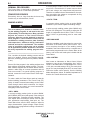
DIP switches on the P.C. Boards allow for custom
configuration of the Power Wave. To access the DIP
switches:
wire drive gear
low speed gear *
high speed gear
TABLE 1
Object Instance
switch 2
switch 1
off
off
off
on
on
off
on
on
6. Replace the cover and screws. The PC board will
“read” the switch at power up, automatically adjusting all control parameters for the speed range
selected.
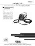
DIP Switch Settings and Locations
electrode polarity
positive *
negative
Instance
0*
1
2
3
*Factory Setting
FIGURE A.1
FEED HEAD BOARD DIP SWITCH
8
7
6
5
4
3
2
1
O
N
WARNING
i
55
E
AV
RW
• Turn off power at the disconnect switch.
-----------------------------------------------------------------------• Remove the top four screws securing the front
access panel.
• Adjust the DIP switches as necessary.
• Replace the panel and screws, and restore power.
F3
WE
PO
O
N
1
2
3
4
5
6
7
8
O
N
1
2
3
4
5
6
7
8
Control Board DIP Switch:
switch 1 = Object Instance LSB 1 (see table 1)
switch 2 = Object Instance MSB 2 (see table 1)
switch 3 = Equipment Group 1 Select
switch 4 = Equipment Group 2 Select
switch 5 = Equipment Group 3 Select
switch 6 = Equipment Group 4 Select
switch 7 = reserved for future use
switch 8 = work sense lead
1 LEAST SIGNIFICANT BIT
2 MOST SIGNIFICANT BIT
CONTROL BOARD DIP SWITCH
O
N
1
2
3
4
5
LOCATION OF DIP SWITCHES IN MACHINE
POWER WAVE F355i (CE)
6
7
8
A-6
A-6
INSTALLATION
I / O RECEPTACLE SPECIFICATIONS
WELDING WITH MULTIPLE POWER
WAVES
CAUTION
Special care must be taken when more than one
Power Wave is welding simultaneously on a single
part. Arc blow and arc interference may occur or
be magnified.
----------------------------------------------------------------------Each power source requires a work lead from the
work stud to the welding fixture. Do not combine all of
the work leads into one lead. The welding travel directions should be in the direction moving away from the
work lead as shown below. Connect all of the work
sense leads from each power source to the work
piece at the end of the weld. (See Figure A.2)
14-Pin Robotic Wire Feeder Connector
Pin
Lead
Function
A
539
Motor +
B
541
Motor C
521
Solenoid +
D
522
Solenoid common
E
845
Tach 2A Differential Signal
F
847
Single Tach input
G
841
+15V Tach Supply
H
844
Tach common
I
Open
Reserved for future use
J
GND
Shielding drain
K
842
Tach 1A Differential Signal
L
843
Tach 1B Differential Signal
M
846
Tach 2B Differential Signal
N
67
Electrode Sense (67)
For the best results when pulse welding, set the wire
size and wire feed speed the same for all the Power
Waves. When these parameters are identical, the
pulsing frequency will be the same, helping to stabilize
the arcs.
VOLTAGE SENSE RECEPTACLE
PIN
LEAD#
FUNCTION
3
21
Work Voltage Sense
1
67
Electrode Voltage Sense
Every welding gun requires a separate shielding gas
regulator for proper flow rate and shielding gas coverage.
PIN
2
3
4
5
6
20
7
RS232 RECEPTACLE
LEAD#
FUNCTION
253
RS232 Receive
254
RS232 Transmit
#
Pin5
#
Pin4
##
Pin20
##
Pin6
251
RS232 Common
PIN
A
B
C
D
E
WIRE FEEDER RECEPTACLE*
LEAD#
FUNCTION
153
Communiction Bus L
154
Communiction Bus H
67
Electrode Voltage Sense
52
Ovdc 51
+40vdc +
Do not attempt to supply shielding gas for two or more
guns from only one regulator.
If an anti-spatter system is in use then each gun must
have its own anti-spatter system.
FIGURE A.2
POWER WAVE F355i
TWO POWER WAVES
POWER WAVE F355i
* Not on Codes 10997
or below.
Travel
Direction
Connect All Work
Sense Leads at the
End of the Joint
Connect All Welding
Work Leads at the
Beginning of the Joint
POWER WAVE F355i (CE)
B-1
OPERATION
SAFETY PRECAUTIONS
B-1
GENERAL DESCRIPTION
Read this entire section of operating instructions
before operating the machine.
WARNING
The Power Wave Robotic power source is designed to
be a part of a modular, multi-process welding system.
Depending on configuration, it can support constant
current, constant voltage, constant power, pulse on
pulse and pulse welding modes.
ELECTRIC SHOCK can kill.
• Unless using cold feed feature, when
feeding with gun trigger, the electrode and drive mechanism are
always electrically energized and
could remain energized several seconds after the welding ceases.
• Do not touch electrically live parts or electrodes
with your skin or wet clothing.
• Insulate yourself from the work and ground.
• Always wear dry insulating gloves.
-----------------------------------------------------------
FUMES AND GASES can be dangerous.
The Power Wave power source is designed to be
used with the Robotic family of Power Feed wire feeders, operating as a system. Each component in the
system has special circuitry to "talk with" the other
system components, so each component (power
source, wire feeder Robotic Controller knows what the
other is doing at all times. These components communicate with Arc Link.
The POWER WAVE F355i (CE) is a high performance, digitally controlled inverter welding power
source capable of complex, high-speed waveform
control. Properly equipped, it can support the GMAW,
GMAW-P and FCAW processes. It carries an output
rating of 350 Amps, 34 Volts at 60% duty cycle and
300 Amps, 32 volts at 100% duty cycle.
• Keep your head out of fumes.
• Use ventilation or exhaust to remove
fumes from breathing zone.
-----------------------------------------------------------
WELDING SPARKS can cause fire or
explosion.
• Keep flammable material away.
• Do not weld on containers that have
held combustibles.
RECOMMENDED PROCESSES AND
EQUIPMENT
RECOMMENDED PROCESSES
The POWER WAVE F355i (CE) can be set up in a
number of configurations, some requiring optional
equipment or welding programs. Each machine is factory preprogrammed with multiple welding procedures,
typically including GMAW, GMAW-P and FCAW for a
variety of materials, including mild steel, stainless
steel, cored wires, and aluminum.
-----------------------------------------------------------
ARC RAYS can burn.
• Wear eye, ear, and body protection.
• The POWER WAVE F355i (CE) is recommended for
Robotic welding with the Fanuc R-J3i.
• This POWER WAVE F355i (CE) is not recommended for processes other than those listed.
Observe additional guidelines detailed in the
beginning of this manual.
REQUIRED EQUIPMENT
Any Arc Link compatible semi-automatic wire feeding
equipment. Specifically, the Power Feed 10 Robotic
Wire drive.
POWER WAVE F355i (CE)
B-2
B-2
OPERATION
LIMITATIONS
• Only Arc Link compatible Power Feed automatic wire
feeders and users interfaces may be used. Other
Lincoln wire feeders or non-Lincoln wire feeders cannot be used.
• POWER WAVE F355i (CE) Output Limitations
The POWER WAVE F355i (CE) will support maximum average output current of 350 Amps @ 60%
duty cycle.
2. HIGH TEMPERATURE LIGHT (thermal overload):
A yellow light that comes on when an over temperature situation occurs. Output is disabled and the
fan continues to run, until the machine cools down.
When cool, the light goes out and output is
enabled.
3. CB1 WIRE FEEDER CIRCUIT BREAKER:
Protects 40 volt DC wire feeder power supply.
DUTY CYCLE AND TIME PERIOD
The duty cycle is based upon a ten minute period. A
60% duty cycle represents 6 minutes of welding and 4
minutes of idling in a ten minute period.
Figure B.1
3
2
5
CONNECTOR STATUS LIGHTS (Per Fig B.1)
1. STATUS LIGHT: A two color light that indicates
system errors. Normal operation is a steady green
light. Error conditions are indicated, per Table B.1.
NOTE: The POWER WAVE F355i (CE) status light
will flash green, and sometimes red and green, for up
to one minute when the machine is first turned on.
This is a normal situation as the machine goes
through a self test at power up.
6
1
4
9
TABLE B.1
Meaning
Light
Condition
Steady Green System OK. Power source communicating normally with wire feeder and its components.
Blinking
Green
Occurs during a reset, and indicates the
POWER WAVE F355i (CE) is mapping
(identifying) each component in the system.
Normal for first 1-10 seconds after power is
turned on, or if the system configuration is
changed during operation
A l t e r n a t i n g Non-recoverable system fault. If the PS
Green and Status light is flashing any combination of
red and green, errors are present in the
Red
POWER WAVE F355i (CE). Read the error
code before the machine is turned off.
Error Code interpretation through the Status
light is detailed in the Service Manual.
Individual code digits are flashed in red with
a long pause between digits. If more than
one code is present, the codes will be separated by a green light.
7
8
CASE FRONT LAYOUT
POWER WAVE F355i (CE)
4. LEAD CONNECTOR (SENSE LEAD)
5. DIAGNOSTIC CONNECTOR (RS-232)
6. WIRE FEEDER RECEPTACLE (14-PIN)
7. NEGATIVE TWIST- MATE TERMINAL
8. POSITIVE TWIST- MATE TERMINAL
9. WIRE FEEDER RECEPTACLE (5 PIN) NOT ON
CODES 10997 OR BELOW.
To clear the error, turn power source off, and
back on to reset. See Troubleshooting
Section.
Steady Red
Non recoverable hardware fault. Generally
indicates nothing is connected to the
POWER WAVE F355i (CE) wire feeder
receptacle. See Trouble Shooting Section.
Blinking Red
Not applicable.
POWER WAVE F355i (CE)
B-3
OPERATION
NOMINAL PROCEDURES
The Power Wave is designed to operate with 3/4"
electrode stick-out for CV and Pulse processes.
FRINGE PROCEDURES
Excessively short or long electrode stick-outs may
function only on a limited basis, if at all.
MAKING A WELD
B-3
In non-synergic modes, the WFS control behaves
more like a conventional CV power source where
WFS and voltage are independent adjustments.
Therefore to maintain the arc characteristics, the operator must adjust the voltage to compensate for any
changes made to the WFS.
• VOLTS / TRIM:
In constant voltage modes (pulse on pulse GMAW,
standard CV) the control adjusts the welding voltage.
WARNING
The serviceability of a product or structure utilizing the welding programs is and must be the sole
responsibility of the builder/user. Many variables
beyond the control of The Lincoln Electric
Company affect the results obtained in applying
these programs. These variables include, but are
not limited to, welding procedure, plate chemistry
and temperature, weldment design, fabrication
methods and service requirements. The available
range of a welding program may not be suitable
for all applications, and the build/user is and must
be solely responsible for welding program selection.
-----------------------------------------------------------------------First, consider the desired welding process and the
part to be welded. Choose an electrode material,
diameter, shielding gas and process (GMAW, GMAWP, etc.)
Second, find the program in the welding software that
best matches the desired welding process. The standard software shipped with the Power Waves encompasses a wide range of common processes and will
meet most needs. If a special welding program is
desired, contact the local Lincoln Electric sales representative.
In pulse synergic welding modes (pulse GMAW only)
the user can change the Trim setting to adjust the arc
length. It is adjustable from 0.500 to 1.500. A Trim setting of 1.000 is a good starting point for most conditions.
• WELDING MODE
Selecting a welding mode determines the output characteristics of the Power Wave power source. For a
more complete description of the welding modes
available in the Power Wave and for a complete set of
weld modes programmed into the Power Wave at the
factory, refer to the weld mode print included with the
Power Wave.
• ARC CONTROL
Also known as Inductance or Wave Control. Allows
operator to vary the arc characteristics from "soft" to
"harsh" in all weld modes. It is adjustable from -10.0 to
+10.0, with a nominal setting of 00.0 (The nominal setting of 00.0 may be displayed as OFF on some Power
Feed wire feeder control panels). See the Welding
Mode descriptions, below, for detailed explanations of
how the Arc Control affects each mode.
To make a weld, the Power Wave needs to know the
desired welding parameters. The Power Feed (PF)
family of feeders communicate settings to the Power
Wave through control cable connection. Arc length,
wire feed speed, arc control, etc. are all communicated digitally via the control cable.
• WFS / AMPS:
In synergic welding modes (pulse on pulse GMAW,
pulse GMAW) WFS (wire feed speed) is the dominant
control parameter, controlling all other variables. The
user adjusts WFS according to factors such as weld
size, penetration requirements, heat input, etc. The
Power Wave then uses the WFS setting to adjust its
output characteristics (output voltage, output current)
according to pre-programmed settings contained in
the Power Wave.
POWER WAVE F355i (CE)
B-4
B-4
OPERATION
CONSTANT VOLTAGE WELDING
Non Synergic CV:
This type of CV mode behaves more like a conventional CV
power source. Voltage and WFS are independent adjustments.
Therefore to maintain the arc characteristics, the operator must
adjust the voltage to compensate for any changes made to the
WFS.
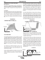
All CV Modes:
Arc Control, often referred to as wave control, adjusts the inductance of the wave shape. The wave control adjustment is similar
to the "pinch" function in that it is inversely proportional to inductance. Therefore, increasing wave control greater than 0.0
results in a harsher, colder arc while decreasing the wave control to less than 0.0 provides a softer, hotter arc. (See Figure
B.2)
FIGURE B.2
CURRENT WAVE FORM (CV)
The Power Wave utilizes "adaptive control" to compensate
for changes in electrical stick-out while welding. (Electrical
stick-out is the distance from the contact tip to the work
piece.) The Power Wave waveforms are optimized for a
0.75" (19mm) stick-out. The adaptive behavior supports a
range of stickouts from 0.50" (13mm) to 1.25" (32mm). At
very low or high wire feed speeds, the adaptive range may
be less due to reaching physical limitations of the welding
process.
Arc Control, often referred to as wave control, in pulse programs usually adjusts the focus or shape of the arc. Wave
control values greater than 0.0 increase the pulse frequency
while decreasing the background current, resulting in a tight,
stiff arc best for high speed sheet metal welding. Wave control values less than 0.0 decrease the pulse frequency while
increasing the background current, for a soft arc good for
out-of-position welding.See Figure B.3)
FIGURE B.3
CURRENT WAVE FORM (PULSE)
Current
Current
Time
PULSE-ON-PULSE™ (GMAW-PP)
Time
Pulse on Pulse™ is a Lincoln process specifically
designed for use in welding relatively thin (less than
1/4" thick) aluminum. It gives weld beads with very
consistent uniform ripple.
PULSE WELDING
Pulse welding procedures are set by controlling an overall
"arc length" variable. When pulse welding, the arc voltage is
highly dependent upon the waveform. The peak current,
back ground current, rise time, fall time and pulse frequency
all affect the voltage. The exact voltage for a given wire feed
speed can only be predicted when all the pulsing waveform
parameters are known. Using a preset voltage becomes
impractical, and instead the arc length is set by adjusting
"trim".
Trim adjusts the arc length and ranges from 0.50 to 1.50,
with a nominal value of 1.00. Trim values greater than 1.00
increase the arc length, while values less than 1.00
decrease the arc length.
All pulse welding programs are synergic. As the wire feed
speed is adjusted, the Power Wave will automatically recalculate the waveform parameters to maintain similar arc
properties.
In Pulse on Pulse modes, two distinct pulse types are
used, instead of the single pulse type normally used in
GMAW-P. A number of high energy pulses are used
to obtain spray transfer and transfer metal across the
arc. Such pulses are shown in Figure B.4. After a
number "N" of such pulses, depending on the wire
feed speed used, an identical number "N" of low energy pulses are performed. These low energy pulses,
shown in Figure B.4, do not transfer any filler metal
across the arc and help to cool the arc and keep the
heat input low.
FIGURE B.4
Current
"N" PULSES
"N" PULSES
HIGH HEAT
PULSES
LOW HEAT
PULSES
PEAK
AMPS
BACKGROUND
AMPS
TIME
POWER WAVE F355i (CE)
B-5
B-5
OPERATION
Power Mode™ is a method of high speed regulation
of the output power whenever an arc is established. It
provides a fast response to changes in the arc. The
higher the Power Mode Setting, the longer the arc. If a
welding procedure is not established, the best way to
determine the Power Mode Setting is by experimentation until the desired output result is established.
The Peak Current, Background Current, and
Frequency are identical for the high energy and low
energy pulses. In addition to cooling the weld down,
the major effect of the low energy pulses is that they
form a weld ripple. Since they occur at very regular
time intervals, the weld bead obtained is very uniform
with a very consistent ripple pattern. In fact, the bead
has its best appearance if no oscillation of the welding
gun ("whipping") is used.(See Figure B.5)
In the Power Mode two variables need to be set:
FIGURE B.5
• Wire Feed Speed
• Power Mode Trim
Setting up a Power Mode procedure is similar to setting a CV MIG procedure. Select a shielding gas
appropriate for a short arc process.
When Arc Control is used in the Pulse on Pulse
modes, it does the same things it does in the other
pulsed modes: decreasing the Arc Control decreases
the droplet transfer and weld deposition rate.
Increasing the Arc Control increases the droplet transfer and weld deposition rate. Since Arc Control varies
weld droplet transfer rate, the Arc Control can be used
to vary the ripple spacing in the weld bead.
• For steel, use 75/25 Ar/CO2 shield gas.
• For stainless, select a Helium blend Tri-Mix.
• For aluminum, use 100% Ar.
Start by setting the wire feed speed based upon material thickness and appropriate travel speed. Then
adjust the Volts/Trim knob as follows:
POWER MODE™
• For steel, listen for the traditional “frying egg”
sound of a good short-arc MIG procedure to know
you have the process set correctly.
• For aluminum, simply adjust the Volts/Trim knob
until the desired arc length is obtained.
The Power Mode™ process was developed by
Lincoln to maintain a stable and smooth arc at low
procedure settings which are needed to weld thin
metal without pop-outs or burning-through. For aluminum welding, it provides excellent control and the
ability to maintain constant arc length. This results in
improved welding performance in two primary types of
applications.
Note the Volts/Trim display is simply a relative number
and DOES NOT correspond to voltage.
Some procedure recommendations appear in Table
B.1.
• Short Arc MIG at low procedure settings.
• Aluminum MIG welding.
Recommended Welding Procedures for Power Mode - Table B.1
Mild Steel
Mild Steel
Mild Steel
Mild Steel
Mild Steel
Mild Steel
WIRE
E4043
E5356
L56
L56
L56
L56
L56
L56
E308L
E308L
WIRE SIZE
0.035
0.035
0.025
0.025
0.030
0.030
0.035
0.035
0.030
0.035
GAS
100% Ar.
100% Ar.
100% CO2
75/25 Ar/CO2
Tri-mix
Tri-mix
80 / 1.5
50 / 0.5
110 / 2.0
WFS / POWER MODE SETTING
MATERIAL THICKNESS
MATERIAL
Aluminum 4043 Aluminum 5356
Stainless Steel Stainless Steel
100% CO2
75/25 Ar/CO2
100% CO2
75/25 Ar/CO2
22 ga.
Not Recommended
100 / 0.8
Not Recommended
90 / 1.0
20 ga.
120 / 1.0
120 / 1.0
100 / 0.7
100 /1.0
18 ga.
140 / 1.7
140 / 1.5
110 / 1.5
110 / 1.5
100 / 2.5
100 / 2.5
110 / 2.0
16 ga.
190 / 2.0
190 / 2.0
125 / 2.0
125 / 2.0
125 / 3.0
125 / 3.0
140 / 2.5
130 / 2.7
260 / 3.0
260 / 3.0
160 / 2.3
160 / 2.3
160 / 3.8
160 / 3.5
210 / 3.0
190 / 3.5
330 / 5.0
330 / 4.5
14 ga.
400 / 2.0
400 / 2.5
230 / 3.5
230 / 3.5
200 / 5.0
200 / 4.5
270 / 5.0
230 / 6.0
10 ga.
500 / 7.0
500 / 7.0
300 / 6.0
300 / 6.0
240 / 6.5
240 / 7.0
325 / 6.5
300 / 7.0
3/16
570 / 9.0
600 / 7.8
400 / 7.5
400 / 7.0
1/4
700 / 9.1
700 / 8.5
12 ga.
COMMENTS
Not
Not
Recommended Recommended
below 400
below 400
WFS
WFS
POWER WAVE F355i (CE)
C-1
ACCESSORIES
OPTIONAL EQUIPMENT
FACTORY INSTALLED
None Available.
FIELD INSTALLED
K940-[ ] Work Voltage Sense Lead Kit
(Sense Lead Kits,10 Ft.,25 Ft.,50 Ft., or 75 Ft. lengths)
K1796-Coaxial Welding Cable-(Requires Adapter K2176-1)
K2176-1 Twist-mate to Lug Adapters
Welding Cable Connectors:
K852-70 1/0-2/0 CABLE
K852-95 2/0-3/0 CABLE
COMPATIBLE LINCOLN EQUIPMENT
Power Feed 10 Robotic Wire Drive
K1785-[ ] 14 Pin to 14 Pin Fanuc
(Control Cable,12 Ft.,16 Ft. or 25 Ft. lengths)
COMMUNICATION INTERFACE
K2436-1 (Not on Codes 10997 or below)
POWER WAVE F355i (CE)
C-1
D-1
MAINTENANCE
SAFETY PRECAUTIONS
WARNING
ELECTRIC SHOCK can kill.
• Do not touch electrically live parts or
electrode with skin or wet clothing.
• Insulate yourself from work and
ground
• Always wear dry insulating gloves.
------------------------------------------------------------------------
EXPLODING PARTS can cause
injury.
• Failed parts can explode or cause other
parts to explode when power is applied.
• Always wear a face shield and long
sleeves when servicing.
------------------------------------------------------------------------
See additional warning information
throughout this Operator’s Manual
----------------------------------------------------------CAPACITOR DISCHARGE PROCEDURE
1. Obtain a power resistor (25 ohms, 25 watts).
2. Hold resistor body with electrically insulated glove.
DO NOT TOUCH TERMINALS. Connect the resistor terminals across the two studs in the position
shown. Hold in each position for 1 second. Repeat
for all four capacitors.
D-1
PERIODIC MAINTENANCE
Calibration of the POWER WAVE F355i (CE) is critical
to its operation. Generally speaking the calibration will
not need adjustment. However, neglected or improperly calibrated machines may not yield satisfactory
weld performance. To ensure optimal performance,
the calibration of output Voltage and Current should
be checked yearly.
CALIBRATION SPECIFICATION
Output Voltage and Current are calibrated at the factory. Generally speaking the machine calibration will
not need adjustment. However, if the weld performance changes, or the yearly calibration check
reveals a problem, contact the Lincoln Electric
Company for the calibration software utility.
The calibration procedure itself requires the use of a
resistance load, and certified actual meters for voltage
and current. The accuracy of the calibration will be
directly affected by the accuracy of the measuring
equipment you use. Detailed instructions are available
with the utility.
RESISTOR
CAPACITOR
TERMINALS
3. Use a DC voltmeter to check that voltage is not
present across the terminals on all four capacitors.
ROUTINE MAINTENANCE
Routine maintenance consists of periodically blowing
out the machine, using a low pressure airstream, to
remove accumulated dust and dirt from the intake and
outlet louvers, and the cooling channels in the
machine.
POWER WAVE F355i (CE)
E-1
TROUBLESHOOTING
E-1
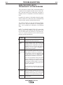
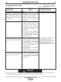
HOW TO USE TROUBLESHOOTING GUIDE
WARNING
Service and Repair should only be performed by Lincoln Electric Factory Trained Personnel.
Unauthorized repairs performed on this equipment may result in danger to the technician and
machine operator and will invalidate your factory warranty. For your safety and to avoid Electrical
Shock, please observe all safety notes and precautions detailed throughout this manual.
__________________________________________________________________________
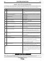
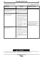
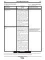
This Troubleshooting Guide is provided to help you
locate and repair possible machine malfunctions.
Simply follow the three-step procedure listed below.
Step 1. LOCATE PROBLEM (SYMPTOM).
Look under the column labeled “PROBLEM (SYMPTOMS)”. This column describes possible symptoms
that the machine may exhibit. Find the listing that
best describes the symptom that the machine is
exhibiting.
Step 3. RECOMMENDED COURSE OF ACTION
This column provides a course of action for the
Possible Cause, generally it states to contact your
local Lincoln Authorized Field Service Facility.
If you do not understand or are unable to perform the
Recommended Course of Action safely, contact your
local Lincoln Authorized Field Service Facility.
Step 2. POSSIBLE CAUSE.
The second column labeled “POSSIBLE CAUSE” lists
the obvious external possibilities that may contribute
to the machine symptom.
CAUTION
If for any reason you do not understand the test procedures or are unable to perform the tests/repairs safely, contact your
Local Lincoln Authorized Field Service Facility for technical troubleshooting assistance before you proceed.
POWER WAVE F355i (CE)
E-2
TROUBLESHOOTING
USING THE STATUS LED TO
TROUBLESHOOT SYSTEM PROBLEMS
The Power Wave / Power Feed are best diagnosed as
a system. Each component (power source, user interface, and feed head) has a status light, and when a
problem occurs it is important to note the condition of
each.
Included in this section is information about the power
source Status LED, and some basic troubleshooting
charts for both machine and weld performance.
The STATUS LIGHT is a two color light that indicates
system errors. Normal operation is a steady green
light. Error conditions are indicated in the following
chart.
NOTE: The POWER WAVE F355i (CE) status light
will flash green, and sometimes red and green, for up
to one minute when the machine is first turned on.
This is a normal situation as the machine goes
through a self test at power up.
Meaning
Light
Condition
Steady Green System OK. Power source communicating normally with wire feeder and its components.
Blinking
Green
Occurs during a reset, and indicates the
POWER WAVE F355i (CE) is mapping
(identifying) each component in the system.
Normal for first 1-10 seconds after power is
turned on, or if the system configuration is
changed during operation
A l t e r n a t i n g Non-recoverable system fault. If the PS
Green and Status light is flashing any combination of
red and green, errors are present in the
Red
POWER WAVE F355i (CE). Read the error
code before the machine is turned off.
Error Code interpretation through the Status
light is detailed in the Service Manual.
Individual code digits are flashed in red with
a long pause between digits. If more than
one code is present, the codes will be separated by a green light.
To clear the error, turn power source off, and
back on to reset. See Troubleshooting
Section.
Steady Red
Non recoverable hardware fault. Generally
indicates nothing is connected to the
POWER WAVE F355i (CE) wire feeder
receptacle. See Trouble Shooting Section.
Blinking Red
Not applicable.
POWER WAVE F355i (CE)
E-2
E-3
TROUBLESHOOTING
E-3
Observe all Safety Guidelines detailed throughout this manual
ERROR CODES FOR THE POWER WAVE
The following is a list of possible error codes that the POWER WAVE F355i (CE) can output via the status light
(see "Troubleshooting the Power Wave / Power Feed System Using the Status LED." If connected to a PF-10/11
these error codes will generally be accompanied by an "Err 006" or "Err 100" on the user interface display.
11
12
Error Code #
CAN communication bus off.
User Interface time out error.
Indication
Probably due to excessive number of communication errors.
UI is no longer responding to the Power Source. The most likely
cause is a fault/bad connection in the communication leads or control cable.
21
Unprogrammed Weld Mode.
22
Empty Weld Table.
23
Weld Table checksum error.
31
Primary overcurrent error.
32
Capacitor "A" under voltage
33
Capacitor "B" under voltage
34
Capacitor "A" over voltage
Contact the Service Department for instructions on reloading the
Welding Software.
Contact the Service Department for instructions on reloading the
Welding Software.
Contact the Service Department for instructions on reloading the
Welding Software.
Excessive Primary current present. May be related to a short in the
main transformer or output rectifier.
Low voltage on the main capacitors. May be caused by improper
input configuration.
When accompanied by an overvoltage error on the same side, it
indicates no capacitor voltage present on that side, and is usually
the result of an open or short in the primary side of the machine.
Excess voltage on the main capacitors. May be caused by improper input configuration.
35
Capacitor "B" over voltage
When accompanied by an under voltage error on the same side, it
indicates no capacitor voltage present on that side, and is usually
the result of an open or short in the primary side of the machine.
36
Thermal error
Indicates over temperature. Usually accompanied by Thermal LED.
Check fan operation. Be sure process does not exceed duty cycle
limit of the machine.
37
Soft start error
41
Secondary overcurrent error
Capacitor precharge failed. Usually accompanied by codes 32-35.
The secondary (weld) current limit has been exceeded. When this
occurs the machine output will phase back to 100 amps, typically
resulting in a condition referred to as "noodle welding"
NOTE: The secondary limit is 570 amps for the standard stud, and
325 amps for all single phase operation.
43
Other
Capacitor delta error
The maximum voltage difference between the main capacitors has
been exceeded. May be accompanied by errors 32-35.
Error codes that contain three or four digits are defined as fatal
errors. These codes generally indicate internal errors on the
Control Board. If cycling the input power on the machine does not
clear the error, try reloading the operating system. If this fails,
replace the control board.
CAUTION
If for any reason you do not understand the test procedures or are unable to perform the tests/repairs safely, contact your
Local Lincoln Authorized Field Service Facility for technical troubleshooting assistance before you proceed.
POWER WAVE F355i (CE)
E-4
E-4
TROUBLESHOOTING
Observe all Safety Guidelines detailed throughout this manual
Observe Safety Guidelines
detailed in the beginning of this manual.
TROUBLESHOOTING GUIDE
PROBLEMS
(SYMPTOMS)
POSSIBLE
CAUSE
OUTPUT PROBLEMS
Major physical or electrical damage
is evident when the sheet metal
covers are removed.
1.
Contact your local authorized
Lincoln Electric Field Service
facility for technical assistance.
Input fuses keep blowing, or input
breaker keeps tripping.
1.
Make certain that fuses or
breakers are properly sized.
See Installation section of this
manual for recommended
fuse and breaker sizes.
Welding procedure is drawing
too much output current, or
duty cycle is too high.
Reduce output current, duty
cycle, or both.
There is internal damage to
the power source. Contact an
authorized Lincoln Electric
Service facility.
2.
3.
Machine will not power up (no
lights, no fan, etc.)
1.
2.
3.
RECOMMENDED
COURSE OF ACTION
If all recommended possible areas
of misadjustments have been
checked and the problem persists,
contact your local Lincoln
Authorized Field Service Facility.
Make certain that the Power
to the POWER WAVE F355i
(CE) is on.
Circuit Breaker CB1 (on Case
Front) may have opened.
Reset. An over load on the
40V Wire Feeder supply may
cause this to trip.
Circuit breaker CB3 (in reconnect area) may have opened.
Reset.
CAUTION
If for any reason you do not understand the test procedures or are unable to perform the tests/repairs safely, contact your local authorized Lincoln Electric Field Service Facility for technical assistance.
POWER WAVE F355i (CE)
E-5
E-5
TROUBLESHOOTING
Observe all Safety Guidelines detailed throughout this manual
Observe Safety Guidelines
detailed in the beginning of this manual.
TROUBLESHOOTING GUIDE
PROBLEMS
(SYMPTOMS)
POSSIBLE
CAUSE
OUTPUT PROBLEMS
Thermal LED is lit.
1. Fan thermostat has opened.
Check for proper fan operation.
(Fan should run whenever output power is on.) Check for
material blocking intake or
exhaust louvers, or for excessive
dirt clogging cooling channels in
machine. Blow air in rear louvers
to remove dirt around the fan.
2. Secondary rectifier or Choke
thermostat has opened. After
machine has cooled, reduce
load, duty cycle, or both. Check
for material blocking intake or
exhaust louvers.
3. DC Bus PC board thermostat
has opened check for excessive
load on 40VDC supply.
Machine won’t weld, can’t get any
output.
1. Input voltage is too low or too
high. Make certain that input
voltage is proper, according to
the Rating Plate located on the
rear of the machine.
2. If the Thermal LED is also lit,
see “Yellow Thermal LED is Lit”
section.
3. Primary current limit has been
exceeded. Possible short in output circuit. Turn machine off.
Remove all loads from the output of the machine. Turn back
on. If condition persists, turn
power off, and contact an authorized Lincoln Electric Field
Service facility.
4. This problem will normally be
accompanied by an error code.
Error codes are displayed as a
series of red and green flashes by
the
status
light.
See
"Troubleshooting the Power Wave
/ Power Feed System Using the
Status LED" section of this text.
RECOMMENDED
COURSE OF ACTION
If all recommended possible areas
of misadjustments have been
checked and the problem persists,
contact your local Lincoln
Authorized Field Service Facility.
CAUTION
If for any reason you do not understand the test procedures or are unable to perform the tests/repairs safely, contact your local authorized Lincoln Electric Field Service Facility for technical assistance.
POWER WAVE F355i (CE)
E-6
E-6
TROUBLESHOOTING
Observe all Safety Guidelines detailed throughout this manual
Observe Safety Guidelines
detailed in the beginning of this manual.
TROUBLESHOOTING GUIDE
PROBLEMS
(SYMPTOMS)
POSSIBLE
CAUSE
OUTPUT PROBLEMS
Machine often “noodle welds” (output is limited to approximately 100
amps) when running a particular
procedure, especially a procedure
with high WFS.
1.Secondary current limit has been
exceeded, and the machine has
phased back to protect itself.
2. Adjust procedure or reduce load
to lower current draw from the
machine.
Machine won’t produce full output.
1. Input voltage may be too low,
limiting output capability of the
power source. Make certain that
the input voltage is proper,
according to the Rating Plate
located on the rear of the
machine.
2. Secondary current or voltage not
be properly calibrated. Check
values displayed on the Power
Feed 10/11 verses readings on
an external meter.
For no apparent reason, the welding characteristics have changed.
1. Check for proper Wire Feed
Speed setting. In CV MIG and
FCAW modes, check for proper
Voltage setting. In the MIG/MAG
pulse modes, check the Trim
setting. These controls are on
the wire feeder.
2. Check for proper shielding gas
mix and flow.
3. Check for loose or faulty weld
cables and cable connections.
RECOMMENDED
COURSE OF ACTION
If all recommended possible areas
of misadjustments have been
checked and the problem persists,
contact your local Lincoln
Authorized Field Service Facility.
The Power Wave is triggered to 1. Check for fault signals from the
weld, but there is no output.
I/O connector. Possible faults
are lack of water flow/ water flow
turned off.
CAUTION
If for any reason you do not understand the test procedures or are unable to perform the tests/repairs safely, contact your local authorized Lincoln Electric Field Service Facility for technical assistance.
POWER WAVE F355i (CE)
E-7
E-7
TROUBLESHOOTING
Observe all Safety Guidelines detailed throughout this manual
PROBLEMS
(SYMPTOMS)
POSSIBLE
CAUSE
RECOMMENDED
COURSE OF ACTION
General degradation of the weld per- 1.Check for feeding problems, bad
formance
connections, excessive loops in
cabling, etc.
2. Verify weld mode is correct for
processes.
3. The power source may require
calibration.
4. Check the actual current displayed on the Power Feed 10 vs.
actual current measured via external meter.
5. Check the actual voltage displayed on the Power Feed 10 vs.
actual voltage measured via external meter.
6. Check the actual WFS displayed
on the Power Feed 10 vs. actual
WFS measured via external
meter.
Excessively long and erratic arc.
The feeder will not cold inch wire.
Arc loss fault on robot.
If all recommended possible areas of
1. Check for proper configuration misadjustments have been checked
and implementation of voltage and the problem persists, contact
your local Lincoln Authorized
sensing circuits.
Field Service Facility.
1. Check for fault signals from the
I/O connector. Possible faults are
lack of water flow/ water cooler
turned off.
1. Possibly caused by wire feeding
problem.
2. Problem - Conduit leading to the
wire feeder has bends or twists,
which can reduce the wire feed
speed. Solution - Remove bends
and twists from conduit.
3. Problem – Conduit leading up to
the wire feeder from the wire reel
is too long. Solution – Use a shorter length of conduit.
CAUTION
If for any reason you do not understand the test procedures or are unable to perform the tests/repairs safely, contact your
Local Lincoln Authorized Field Service Facility for technical troubleshooting assistance before you proceed.
POWER WAVE F355i (CE)
L8
440460V
H5
380415V
H4
6A
3
4
7
8
4
3
8
31
32
202
204
209
205
206
C1,C3
+
FAN
207
42
3
31
32
3
1
F
+
D
_
_
4
2
COM1A
C
B
A
CB2
2.5A
31A
6
2
H1
W
TP2
R
B
TP3
SNB
20
40
S
N
U
B
B
E
R
X2
41
204
208
OUTPUT
RECTIFIER
A
IN
T
OU
IPR
IPR
3
MAIN
TRANSFORMER
X4
15A
CB1
N.E.
FAN
4
PW F355i CE
3
FAN
31B
2
1
PW F355i
505
504
FAN1
TP1
A
7
5
3
1
1010
1020
610
605
608
616
1001
1002
J22A P22
8
4
32
31
632
P22A (TO SWITCHBOARD)
2
4
1
32A
INPUT
BRIDGE
209
FAN
FAN
FAN
207
201
J21
208
203
FAN1
C2,C4
3200/300
3200/300
P22 (TO SWITCHBOARD)
2
1
J22
2
1
J20
6
5
H1 H2 H3 H4 H5 H6
5
A
FAN
FAN
607
615
716
715
611
612
609
602
SWITCH
X4
41
X3
T
OU
X1
IPR
201
42
IN
C
SE
B
~
66B
65B
66
66C
J90
1 234
65
65C
505
5
J42
2
1
4
6
3
2
4
J41
3
1
407 410
412 411 408 475 477
7
1
J43
8
2
4
5
6
401
402
1104
POWER
9 10 11 12
3
403 406
405
1103
610
401
403A
R2
10Y
7
15
16
12
11
4
3
7
1
8
J4
2
L3
406 405
403A 408 407
412 411 410 402 401A
4
3
5
9
3
1
J5
6
4
2
J6
J7
J3
4
3
8
4
2
7
4
3
254
253
251
901
903
1W
1B
2W
2B
1
6
2
1
1104
~
886
51
9
1
1
13
25
5
1
522
7
6
2
1
3
4
3
8
2
4
504
903B
R1
2
3
J1,J6,J7,
J85, J87
16
8
6
1
J52, J86
5
6
7
J85
J84
J83
J82
J81
7
10
5
541
A
BLACK
J
6
5
4
3
2
I
B
K
521
3
RED
2
4
1
3
4
5
1
1
7
8
7
4
21
8
3
5
4
1
12
6
1
2
J10A,
J10B
G4146
B
LEGEND
ALL MACHINES
OPTION
COMPONENT OUTLINE
COLOR CODE:
B = BLACK
G = GREEN
R = RED
W = WHITE
U = BLUE
N = BROWN
Y = YELLOW
2
VOLTAGE SENSE
RECEPTACLE
1
9
67B
2
3
4
J4, J43
6
16 15 14 13 12 11 10
CONNECTOR CAVITY NUMBERING SEQUENCE
(VIEWED FROM COMPONENT SIDE OF BOARD)
6
6
1
7
2
J87
TO ROBOTIC CONTROLLER
J8,
J20,J21,
J47, J84
522
BLACK
847
3
8
J86
GREEN
E
F
67B
4
1
5
10 9
9
J2,J5,J11,
J22, J41,
J46, J81,
J9, J42, J83
J82
1
L7
FEED HEAD P.C. BOARD
D
M
G
C
L
N
H
WIRE FEEDER
RECEPTACLE
WHITE
8
16 15 14 13 12 11 10
1
8
4
4
1
6
5
2
3
901B
539
GND-A
67A
BLACK
847
BLACK
RED
GREEN
WHITE
BLACK
4
2
3
3
1
1
4
2
40VDC BUS
BOARD
54
53
154A
52
153A
51
521
880
541
886
539
J47
J46
502
FRONT VIEW OF MACHINE
_
STATUS
RED/GREEN
LED
THERMAL
YELLOW
LED
14
880
52
477
475
253 251
254
~
ELECTRICAL SYMBOLS PER E1537
FAN
CASE
BASE
TOP CENTER
SHROUD
FRONT
PANEL
PROTECTIVE BONDING CIRCUIT
5
10 9
J2
J1
CONTROL
BOARD
J10A J10B
2
J11
1
3
1
2
2
153A
154A
1010
1
1103
1001
12 11 10
9
1
2 10
13
14
5
6
15
16
J8
J9
LEFT SIDE OF MACHINE
403
612
611
3
8
4
1W
7
8
5
1
7
6
8
3
2
4
4
2
1
6
5
3
1B
715
716
802
806
801
804
901
903
609
502
503
602
605
608
616
607
615
2W
2B
67A
21
1002 1020
66C
65C
65
66
DIAGRAMS
NOTE: This diagram is for reference only. It may not be accurate for all machines covered by this manual. The specific diagram for a particular code is pasted inside
the machine on one of the enclosure panels. If the diagram is illegible, write to the Service Department for a replacement. Give the equipment code number.
2400/80
C5
X2
CONTROL
RECTIFIER
~
~
506
503
CHOKE
IPR
CURRENT
TRANSDUCER
C
SE
7
2
6
205
RIGHT SIDE OF MACHINE
+
N.A. SINCE COMPONENTS OR CIRCUITRY OF A PRINTED CIRCUIT BOARD MAY CHANGE WITHOUT AFFECTING
THE INTERCHANGEABILITY OF A COMPLETE BOARD, THIS DIAGRAM MAY NOT SHOW THE EXACT
COMPONENTS OR CIRCUITRY HAVING A COMMON CODE NUMBER.
N.B. PLACE "A" LEAD ON APPROPRIATE CONNECTION FOR INPUT VOLTAGE. CONNECTION SHOWN IS FOR
550-575V OPERATION. (PW F355i CE HAS 380-415 V CONNECTION)
N.C. LEADS A1, B1, C1 ARE PART OF THE INPUT POWER LINE FILTER & IT IS PRESENT ONLY ON PW F355i CE.
N.D. TERMINAL BLOCK PRESENT ONLY ON PW F355i CE.
N.E. ON PW F355i CE, MOV's ARE IN THE INPUT POWER LINE FILTER.
N.F. TOROID ON GROUND LEAD PRESENT ONLY ON PW F355i CE.
J52
AUXILIARY
TRANSFORMER
H6
550575V
N.B.
A
CB3
( 380-575VAC POSITION )
NOTES:
N.C.
REAR OF MACHINE
C1
115V
G
(G/Y)
N.F.
COM 2
A1
B1
42V
U
(U) B
INPUT (B) R V
W
(N)W
COM 1
WIRING DIAGRAM POWER WAVE F355i FOR CODE 10997
+
N.D.
-
xxxxxxx
+
POWER WAVE F355i (CE)
802
804
801
806
-
+
+
401A
xxxxxxx
xxxxxxx
BLACK
F-1
F-1
L8
440460V
H5
380415V
H4
6A
3
4
7
8
4
3
8
31
32
202
204
209
205
206
+
FAN
207
42
3
31
32
2
4
1
3
F
+
D
_
_
COM1A
C
B
A
CB2
2.5A
31A
6
2
R
H1
W
TP2
B
TP3
SNB
20
40
S
N
U
B
B
E
R
X2
41
204
208
OUTPUT
RECTIFIER
A
IN
T
OU
IPR
IPR
3
MAIN
TRANSFORMER
X4
15A
CB1
N.E.
FAN
4
PW F355i CE
3
FAN
31B
2
1
PW F355i
505
504
FAN1
TP1
A
7
5
3
1
1010
1020
610
605
608
616
1001
1002
J22A P22
8
4
32
31
632
P22A (TO SWITCHBOARD)
2
4
1
32A
INPUT
BRIDGE
209
FAN
FAN
FAN
207
201
J21
208
203
FAN1
C2,C4
3200/300
3200/300
P22 (TO SWITCHBOARD)
2
1
J22
2
1
6
5
J20
SWITCH
H1 H2 H3 H4 H5 H6
5
A
FAN
FAN
607
615
716
715
611
612
609
602
C1,C3
X4
41
X1
PR
X3
UT
I-O
201
42
C
SE
B
~
66B
65B
66
66C
J90
1 234
65
65C
505
5
J42
2
1
4
6
3
2
4
J41
3
1
407 410
412 411 408 475 477
7
1
J43
8
2
4
5
6
401
402
1104
POWER
9 10 11 12
3
403 406
405
1103
401
403A
R2
10Y
7
15
16
12
11
4
3
7
1
8
J4
2
L3
406 405
403A 408 407
412 411 410 402 401A
4
3
5
9
3
1
J5
6
4
2
J6
J7
4
3
8
4
2
7
4
3
254
253
251
901
903
1W
1B
2W
2B
1
6
2
1
1104
~
886
51
9
1
1
13
25
5
522
7
6
1
8
4
2
3
1
3
4
2
880
886
51A
521
541
539
R1
J1,J6,J7,
J85, J87
16
8
6
1
J52, J86
5
6
7
8
J85
J84
J83
J82
J81
7
541
A
BLACK
J
6
5
4
3
2
I
B
K
1
521
3
RED
2
4
1
3
10
4
51
1
2
5
1
A
J87
1
7
4
8
21
7
3
5
C
D
ARCLINK
RECEPTACLE
4
1
2
2
VOLTAGE SENSE
RECEPTACLE
1
9
12
6
67B
67C
1
2
J10A,
J10B
G5375
A.02
LEGEND
ALL MACHINES
OPTION
COMPONENT OUTLINE
COLOR CODE:
B = BLACK
G = GREEN
R = RED
W = WHITE
U = BLUE
N = BROWN
Y = YELLOW
3
67C
4
J4, J43
6
16 15 14 13 12 11 10
8
B
E
TO ROBOTIC CONTROLLER
51A
CONNECTOR CAVITY NUMBERING SEQUENCE
(VIEWED FROM COMPONENT SIDE OF BOARD)
6
6
7
J8,
J20,J21,
J47, J84
522
BLACK
847
3
8
J86
GREEN
E
F
67B
4
1
5
10 9
9
J2,J5,J11,
J22, J41,
J46, J81,
J9, J42, J83
J82
5
L7
154B
154A
153B
153A
52
52A
FEED HEAD P.C. BOARD
D
M
G
C
L
N
H
WIRE FEEDER
RECEPTACLE
WHITE
8
16 15 14 13 12 11 10
1
2
3
4
5
4
2
6
3
1
3
1
4
3
1
2
4
2
901B
539
GND-A
67A
BLACK
BLACK
RED
GREEN
WHITE
BLACK
847
903B
54
53
154A
52A
153A
J47
40VDC BUS
J46
BOARD
502
FRONT VIEW OF MACHINE
_
STATUS
RED/GREEN
LED
THERMAL
YELLOW
LED
14
880
52
477
475
253 251
254
~
ELECTRICAL SYMBOLS PER E1537
FAN
CASE
BASE
TOP CENTER
SHROUD
FRONT
PANEL
PROTECTIVE BONDING CIRCUIT
5
10 9
J3
J2
J1
CONTROL
BOARD
J10A J10B
2
J11
1
3
1
2
2
153B
154B
1010
1
1103
1001
12 11 10
9
1
2 10
13
14
5
6
15
16
J8
J9
LEFT SIDE OF MACHINE
403
612
611
3
8
4
1W
7
8
5
1
7
6
8
3
2
4
4
2
1
6
5
3
1B
715
716
802
806
801
804
901
903
609
502
503
602
610
605
608
616
607
615
2W
2B
67A
21
1002 1020
66C
65C
65
66
504
DIAGRAMS
NOTE: This diagram is for reference only. It may not be accurate for all machines covered by this manual. The specific diagram for a particular code is pasted inside
the machine on one of the enclosure panels. If the diagram is illegible, write to the Service Department for a replacement. Give the equipment code number.
C5
2400/80
X2
CONTROL
RECTIFIER
~
~
506
503
CHOKE
I-IN
PR
CURRENT
TRANSDUCER
C
SE
7
2
6
205
RIGHT SIDE OF MACHINE
+
N.A. SINCE COMPONENTS OR CIRCUITRY OF A PRINTED CIRCUIT BOARD MAY CHANGE WITHOUT AFFECTING
THE INTERCHANGEABILITY OF A COMPLETE BOARD, THIS DIAGRAM MAY NOT SHOW THE EXACT
COMPONENTS OR CIRCUITRY HAVING A COMMON CODE NUMBER.
N.B. PLACE "A" LEAD ON APPROPRIATE CONNECTION FOR INPUT VOLTAGE. CONNECTION SHOWN IS FOR
550-575V OPERATION. (PW F355i CE HAS 380-415 V CONNECTION)
N.C. LEADS A1, B1, C1 ARE PART OF THE INPUT POWER LINE FILTER & IT IS PRESENT ONLY ON PW F355i CE.
N.D. TERMINAL BLOCK PRESENT ONLY ON PW F355i CE.
N.E. ON PW F355i CE, MOV's ARE IN THE INPUT POWER LINE FILTER.
N.F. TOROID ON GROUND LEAD PRESENT ONLY ON PW F355i CE.
J52
AUXILIARY
TRANSFORMER
H6
550575V
N.B.
A
CB3
( 380-575VAC POSITION )
NOTES:
N.C.
REAR OF MACHINE
C1
115V
G
(G/Y)
N.F.
42V
N.D.
COM 1
A1
B1
+
U
(U) B
INPUT (B) R V
W
(N)W
COM 2
WIRING DIAGRAM POWER WAVE F355i FOR CODE 11252
-
xxxxxxx
+
POWER WAVE F355i (CE)
802
804
801
806
-
+
+
401A
xxxxxxx
xxxxxxx
BLACK
F-2
F-2
F-3
CONNECTION DIAGRAM
F-3
Connection Diagram Semi-automatic "Simple System"
(Electrode Positive, CV / Pulse Configuration shown)
SEE SECTION A-4, Power Wave / Power Feed Wire
Feeder Interconnections
COMMUNICATION INTERFACE
OPTIONAL (K2436-1)
NOT ON CODES 10997 OR BELOW.
POWER WAVE F355i
VOLTAGE SENSE LEADS
(OPTIONAL) K940
WIRE
FEEDER
TO
WORK
CONTROL CABLE K1785
FANUC R-J3i
POWER WAVE F355i (CE)
14.64
17.20
10.06
.40
3.37
25.15
27.60
DIMENSION PRINT
POWER WAVE F355i (CE)
M19982
A
.51
.81
F-4
F-4
NOTES
POWER WAVE F355i (CE)
WARNING
Spanish
AVISO DE
PRECAUCION
French
ATTENTION
German
WARNUNG
Portuguese
ATENÇÃO
● Do not touch electrically live parts or
● Keep flammable materials away.
● Wear eye, ear and body protection.
● Mantenga el material combustible
● Protéjase los ojos, los oídos y el
electrode with skin or wet clothing.
● Insulate yourself from work and
ground.
● No toque las partes o los electrodos
bajo carga con la piel o ropa mojada.
● Aislese del trabajo y de la tierra.
● Ne laissez ni la peau ni des vête-
ments mouillés entrer en contact
avec des pièces sous tension.
● Isolez-vous du travail et de la terre.
● Berühren Sie keine stromführenden
Teile oder Elektroden mit Ihrem
Körper oder feuchter Kleidung!
● Isolieren Sie sich von den
Elektroden und dem Erdboden!
● Não toque partes elétricas e elec-
trodos com a pele ou roupa molhada.
● Isole-se da peça e terra.
fuera del área de trabajo.
● Gardez à l’écart de tout matériel
inflammable.
● Entfernen Sie brennbarres Material!
cuerpo.
● Protégez vos yeux, vos oreilles et
votre corps.
● Tragen Sie Augen-, Ohren- und Kör-
perschutz!
● Mantenha inflamáveis bem guarda-
dos.
● Use proteção para a vista, ouvido e
corpo.
Japanese
Chinese
Korean
Arabic
READ AND UNDERSTAND THE MANUFACTURER’S INSTRUCTION FOR THIS EQUIPMENT AND THE CONSUMABLES TO BE
USED AND FOLLOW YOUR EMPLOYER’S SAFETY PRACTICES.
SE RECOMIENDA LEER Y ENTENDER LAS INSTRUCCIONES DEL FABRICANTE PARA EL USO DE ESTE EQUIPO Y LOS
CONSUMIBLES QUE VA A UTILIZAR, SIGA LAS MEDIDAS DE SEGURIDAD DE SU SUPERVISOR.
LISEZ ET COMPRENEZ LES INSTRUCTIONS DU FABRICANT EN CE QUI REGARDE CET EQUIPMENT ET LES PRODUITS A
ETRE EMPLOYES ET SUIVEZ LES PROCEDURES DE SECURITE DE VOTRE EMPLOYEUR.
LESEN SIE UND BEFOLGEN SIE DIE BETRIEBSANLEITUNG DER ANLAGE UND DEN ELEKTRODENEINSATZ DES HERSTELLERS. DIE UNFALLVERHÜTUNGSVORSCHRIFTEN DES ARBEITGEBERS SIND EBENFALLS ZU BEACHTEN.
● Keep your head out of fumes.
● Use ventilation or exhaust to
● Turn power off before servicing.
● Do not operate with panel open or
guards off.
remove fumes from breathing zone.
● Los humos fuera de la zona de res-
piración.
● Mantenga la cabeza fuera de los
humos. Utilice ventilación o
aspiración para gases.
● Gardez la tête à l’écart des fumées.
● Utilisez un ventilateur ou un aspira-
● Desconectar el cable de ali-
mentación de poder de la máquina
antes de iniciar cualquier servicio.
● Débranchez le courant avant l’entre-
tien.
teur pour ôter les fumées des zones
de travail.
● Vermeiden Sie das Einatmen von
Schweibrauch!
● Sorgen Sie für gute Be- und
Entlüftung des Arbeitsplatzes!
● Mantenha seu rosto da fumaça.
● Use ventilação e exhaustão para
remover fumo da zona respiratória.
● Strom vor Wartungsarbeiten
● No operar con panel abierto o
guardas quitadas.
● N’opérez pas avec les panneaux
ouverts ou avec les dispositifs de
protection enlevés.
● Anlage nie ohne Schutzgehäuse
abschalten! (Netzstrom völlig öffnen; Maschine anhalten!)
oder Innenschutzverkleidung in
Betrieb setzen!
● Não opere com as tampas removidas.
● Desligue a corrente antes de fazer
● Mantenha-se afastado das partes
serviço.
● Não toque as partes elétricas nuas.
● Não opere com os paineis abertos
moventes.
ou guardas removidas.
WARNING
Spanish
AVISO DE
PRECAUCION
French
ATTENTION
German
WARNUNG
Portuguese
ATENÇÃO
Japanese
Chinese
Korean
Arabic
LEIA E COMPREENDA AS INSTRUÇÕES DO FABRICANTE PARA ESTE EQUIPAMENTO E AS PARTES DE USO, E SIGA AS
PRÁTICAS DE SEGURANÇA DO EMPREGADOR.
• World's Leader in Welding and Cutting Products •
• Sales and Service through Subsidiaries and Distributors Worldwide •
Cleveland, Ohio 44117-1199 U.S.A. TEL: 216.481.8100 FAX: 216.486.1751 WEB SITE: www.lincolnelectric.com