1
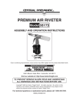
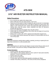
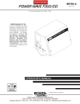
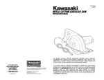
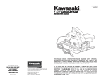
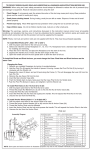
AIR HYDRAULIC RIVETER
167
ASSEMBLY AND OPERATING INSTRUCTIONS
Due to continuing improvements, actual product may differ slightly from the product described herein.
®
3491 Mission Oaks Blvd., Camarillo, CA 93011
Visit our Web site at: http://www.harborfreight.com
TO PREVENT SERIOUS INJURY,
READ AND UNDERSTAND ALL WARNINGS
AND INSTRUCTIONS BEFORE USE.
Copyright © 2005 by Harbor Freight Tools®. All rights reserved. No portion of this
manual or any artwork contained herein may be reproduced in any shape or form
without the express written consent of Harbor Freight Tools.
For technical questions, please call 1-800-444-3353.
PRODUCT SPECIFICATIONS
Rivet Capacity
3/ ", 1/ ", 5/ ",
32
8
32
Operating Air Pressure
90 PSI
& 3/16" sized pins
Air Consumption
4 CFM @ 90 PSI
Air Inlet Size
1/ "-18 NPT
4
3/ ", 1/ ", 5/ ", 3/ "
32
8
32
16
11" H x 9" L x 31/8" W
37/8 Pounds
Nosepiece Sizes
Overall Dimensions
Net Weight
SAVE THIS MANUAL
You will need this manual for the safety warnings and precautions, assembly,
operating, inspection, maintenance and cleaning procedures, parts list and assembly
diagram. Keep your invoice with this manual. Write the invoice number on the inside of the
front cover. Keep this manual and invoice in a safe and dry place for future reference.
UNPACKING
When unpacking, check to make sure that all the parts and accessories listed on
page 11 are included, and the product is intact and undamaged. If any parts are missing or
broken, please call Harbor Freight Tools at the number shown on the cover of this manual
as soon as possible.
SAFETY WARNINGS AND PRECAUTIONS
1.
WARNING! Use eye and hearing protection. Always wear ANSI approved
safety impact goggles, hearing protection, and heavy-duty work gloves when
using this Riveter. Other people in the work area must also wear appropriate
ANSI approved safety equipment.
2.
Keep work area clean. Cluttered areas invite accidents.
3.
Stay within air pressure capacity. Never operate the Riveter above 90 PSI.
4.
Observe work area conditions. Keep work area well lit. Do not use pneumatic
tools in the presence of flammable gases or liquids.
5.
Keep children away. Children must never be allowed in the work area. Do not let
them handle machines, tools, extension cords, or air hoses.
6.
Store idle equipment. When not in use, tools must be stored in a dry location to
inhibit rust. Always lock up tools and keep out of reach of children.
7.
Use the right tool for the job. Do not attempt to force a small tool or attachment to
do the work of a larger industrial tool. There are certain applications for which this
tool was designed. It will do the job better and more safely at the rate for which it
SKU 167
For technical questions, please call 1-800-444-3353
PAGE 2
was intended. Do not modify this tool, and do not use this tool for a purpose for
which it was not intended.
8.
Dress properly. Do not wear loose clothing or jewelry as they can be caught in
moving parts. Protective, electrically nonconductive clothes and nonskid footwear
are recommended when working. Wear restrictive hair covering to contain long
hair.
9.
Do not overreach. Keep proper footing and balance at all times. Do not reach over
or across running tools or air hoses.
10.
Disconnect air hose and release any built-up air pressure. Never service the
Riveter or disassemble with the air hose attached. Always release any built-up air
even after disconnecting hose. Disconnect the Riveter when not in use.
11.
Remove adjusting wrenches. Check that adjusting wrenches are removed from
the tool and work surface before attaching to an air source.
12.
Avoid unintentional starting. Be sure the Trigger (40) is in the OFF position when
not in use and before plugging in. Do not carry any tool with your finger on the
Trigger, whether it is attached to an air source or not. Do not point the tool towards
yourself or anyone.
13.
Stay alert. Watch what you are doing. Use common sense. Do not operate any tool
when you are tired.
14.
Check for damaged parts. Before using any tool, any part that appears damaged
should be carefully checked to determine that it will operate properly and perform its
intended function. Check for alignment and binding of moving parts, any broken
parts, and any other condition that may affect proper operation. Any part that is
damaged should be properly repaired or replaced by a qualified technician. Do not
use the tool if the Trigger does not operate properly.
15.
Replacement parts and accessories. This product is to be repaired and serviced
only by a qualified technician. When this product is serviced, only identical
replacement parts should be used. Use of any other parts will void the warranty.
Only use accessories intended for use with this tool. Approved accessories are
available from Harbor Freight Tools.
16.
Do not operate tool if under the influence of alcohol or drugs. Read warning
labels if taking prescription medicine to determine if your judgement or reflexes are
impaired while taking drugs. If there is any doubt, do not operate the tool.
17.
Maintenance. The maintenance outlined in the “Maintenance” section should be
performed regularly. For your safety, this product should be serviced or repaired
regularly only by a qualified technician.
18.
Compressed air only. Never use combustible gas as a power source.
19.
Fire the Rivets into an appropriate work surface only. This Riveter is designed
for use on metal objects only, and is not suitable for soft surfaces.
SKU 167
For technical questions, please call 1-800-444-3353
PAGE 3
20.
Do not fire the Rivets too close to the edge of a workpiece. They may split the
workpiece and cause it to fly free, causing personal injury.
21.
Transport the Riveter safely. Always disconnect the air supply when moving the
tool in the workplace. Carry the tool by the handle and avoid contact with the Trigger
(40).
22.
Avoid working alone. If an accident happens, an assistant can bring help.
23.
Always attach the Safety Cap (23) to the Riveter prior to using the tool. Make
sure the slot in the Safety Cap faces upward to avoid spilling used Rivet Pins.
24.
WARNING! Some dust created by power sanding, sawing, grinding, drilling,
and other construction activities contain chemicals known (to the State of California)
to cause cancer, birth defects, or other reproductive harm.
Some examples of these chemicals are:
* Lead from lead-based paints,
* Crystalline silica from bricks, cement, and other masonry products,
* Arsenic and chromium from chemically treated lumber.
(California Health & Safety Code § 25249.5, et seq.)
25.
WARNING! The warnings, cautions, and instructions discussed in this instruction
manual cannot cover all possible conditions and situations that may occur. It must
be understood by the operator that common sense and caution are factors which
cannot be built into this product, but must be supplied by the operator.
ASSEMBLY INSTRUCTIONS
1.
For best service, you should incorporate an oiler, regulator, and inline filter, as shown
in the diagram below. Hoses, couplers, oilers, regulators, and filters are all available
at Harbor Freight Tools. NOTE: If an automatic oiler is not used, put 3-5 drops of
pneumatic Tool Oil (not included) in the tool’s quick connector before each use.
(See Figure A.)
REGULATOR
FIGURE A
SKU 167
OILER FILTER
For technical questions, please call 1-800-444-3353
PAGE 4
2.
Prior to use, the Riveter requires the attachment of the Quick Connector (53) to its
Air Cylinder (29). To do so, make sure the screen Air Filter is properly seated in the
Air Cylinder. Wrap approximately 3” of pipe thread seal tape (not included) around
the male threads of the Quick Connector. Then, firmly tighten the Quick Connector
into the Air Cylinder. (See Figure B.)
AIR CYLINDER
(29)
FIGURE B
QUICK CONNECTOR
(53)
To Prime The Riveter:
1.
WARNING! Make sure the Riveter is disconnected from its air supply hose
prior to performing any maintenance, service, or changing accessories.
2.
To prime the Riveter, use the Spanner (36) to unscrew and remove the Cylinder
Cap (33) from the bottom of the Riveter. (See Figure C, next page.)
3.
Use a pair of pliers (not included) to remove the Piston Assembly (30 thru 33) from
the Air Cylinder (29). (See Figure C.)
4.
Hold the Air Cylinder (29) upside down, and pour in hydraulic oil (not included).
The fill level should only reach the top of the Frame (15). (See Figure C.)
SKU 167
For technical questions, please call 1-800-444-3353
PAGE 5
5.
Insert the Piston Assembly (30 thru 33) back into the Air Cylinder (29).
(See Figure C.)
6.
Use the Spanner (36) to firmly screw the Cylinder Cap (33) back onto the Air Cylinder
(29). (See Figure C.)
AIR CYLINDER
(29)
SPANNER
(36)
PISTON ASSY.
(30 THRU 33)
AIR CYLINDER
(29)
CYLINDER CAP
(33)
AIR PISTON LOCK NUT
(30-3)
FIGURE C
REV 09/05
SKU 167
For technical questions, please call 1-800-444-3353
PAGE 6
OPERATING INSTRUCTIONS
Nosepieces:
1.
The Riveter comes with four Nosepieces. The Nosepiece part numbers and sizes
are as follows: (1A = 3/16”), (1B = 5/32”), (1C = 1/8”), (1D = 3/32”). (See Figure D.)
2.
Use the Spanner (36) when changing Nosepieces. (See Figure D.)
FRAME HEAD
(11)
SAFETY CAP
(23)
FRAME
CAP NUT
(22)
FIGURE D
NOSEPIECE
(1A, 1B, 1C, 1D)
TRIGGER
(40)
QUICK CONNECTOR
(53)
To Operate The Riveter:
1.
Make sure the Safety Cap (23) is firmly secured to the Riveter by tightening the
Frame Cap Nut (22). Also, make sure the slot in the Safety Cap is turned upward to
avoid spilling used rivet pins. (See Figure D.)
2.
Depending on the size of rivet’s pin (not included) used, attach the corresponding
Nosepiece size (3/16”, 5/32”, 1/8”, or 3/32”) with the Spanner (36).
(See Figure D.)
3.
IMPORTANT: When drilling rivet holes in a workpiece, make sure to use the same
diameter drill bit as the outer diameter of rivet you will be using.
4.
Attach an air hose to the Quick Connector (53) of the Riveter. (See Figure D.)
5.
Turn on the air compressor, and set its regulator at 90 PSI. Do not exceed 90 PSI.
SKU 167
For technical questions, please call 1-800-444-3353
PAGE 7
6.
Insert the small end of a rivet fully through the Nosepiece (1A, 1B, 1C, or 1D).
CAUTION! Make sure to NEVER to touch the Trigger (40) when you are inserting
rivets. (See Figure D.)
7.
Insert the rivet through the predrilled hole in the workpiece.
8.
Hold the Riveter firmly with both hands, and squeeze the Trigger (40) to activate the
Riveter. Repeat as necessary. Then, release pressure on the Trigger.
(See Figure D.)
9.
When finished using the Riveter, turn off the air compressor. Squeeze the Trigger
again to release any compressed air in the Riveter. Disconnect the air hose from
the tool. Then, store the Riveter in a clean, dry, safe location out of reach of children.
(See Figure D.)
INSPECTION, MAINTENANCE, AND CLEANING
1.
WARNING! Always wear ANSI approved safety impact goggles when
performing any inspection, maintenance, or cleaning procedures.
2.
WARNING! Prior to performing any inspection, maintenance, or cleaning of
the Riveter, make sure to disconnect the air hose from the tool. Then, squeeze the
Trigger (40) again to release any compressed air in the Riveter.
3.
To clean the exterior of the Riveter, wipe with a clean, damp cloth using a mild
detergent or mild solvent. Do not immerse the tool in liquids.
4.
To clean and change the Jaws:
A. Unscrew and remove the Frame Head (11), using the Spanner (36).
(See Assy. Diagram.)
B. Use the Spanner (36) to unscrew and remove the Jaw Case (6). Use care as
there is a Spring (10) behind the Jaw Case (6) which may fly out.
(See Assy. Diagram.)
C. Remove the Jaws (7) from inside the Jaw Case (6).
(See Assy. Diagram.)
SKU 167
For technical questions, please call 1-800-444-3353
PAGE 8
D. If you are going to clean the Jaws (7), use a steel brush and mild solvent. Then,
apply a light coat of machine oil to the Jaws. If you are going to replace the
Jaws, the entire assembly (6, 7, 8, 9, & 10) must be replaced at the same time,
due to the possibility of additional parts being damaged when the Jaws were
damaged. (See Assy. Diagram.)
E. Insert the Jaws (7) back into the Jaw Case (6).
(See Assy. Diagram.)
F. When reassembling the Jaw Case (6), make sure the wedge on the Jaw Pusher’s
(8) head lines up in between the Jaws, pushing them slightly apart.
(See Assy. Diagram.)
G. Check the distance from the head of the Jaw Case (6) to the mounting threads of
the Frame Head (11) using the gauge on the Spanner (35). With the gauge at a
slight incline, the back of the gauge should rest on the beginning of the Frame
Head threads, while the front of the gauge should rest on the front edge of the
Jaw Case (6). If it does not, tighten/loosen the Jaw Case until the distance is
corrected. (See Figure E.)
5.
When storing, always store the Riveter in a clean, dry, safe location out of reach of
children.
6.
WARNING! All maintenance, service, and repairs not mentioned in this manual
must only be performed by a qualified service technician.
SPANNER GAUGE (35)
FIGURE E
SKU 167
JAW CASE
(6)
(THREADS)
FRAME HEAD (11)
For technical questions, please call 1-800-444-3353
PAGE 9
TROUBLESHOOTING
Problem
Possible Cause
Worn or damaged Jaws.
Jaws slipping.
Jaws will not open.
Likely Solution
Replace Jaws.
Loose Nosepiece.
Tighten Nosepiece.
Dir ty Jaws.
Clean Jaws.
Rivet pin not properly inser ted Make sure that Pin is fully inser ted.
into Riveter.
Stroke is too shor t.
Weak pulling action.
Leaking air.
Low oil.
Prime Riveter.
Rivet wrong size.
Use proper rivet length.
Low air pressure.
Check regulator.
Broken/inadequate air
compressor.
Have compressor ser viced by a
qualified technician/upgrade to
compressor of sufficient capability.
Poor hose connections.
Reconnect using pipe thread seal tape.
Damaged O-Ring.
Replace O-Ring.
Dir ty Air Valve.
Clean and lubricate with pneumatic tool
oil.
Dir ty airline inlet.
Clean and lubricate with pneumatic tool
oil.
PARTS LIST
Part
1A
1B
1C
Description
Nosepiece (3/16")
Nosepiece (5/32")
(1/
Part
Description
Part
Description
20
Hanging Clip
36
Spanner
21
Frame Cap
37
Trigger Pin
22
Frame Cap Nut
38
Connector
23
Safety Cap
39
Trigger Rod
6
Nosepiece 8")
Nosepiece (3/32")
Jaw Case
24
Setting Screw Pin
40
Trigger
7
Jaw
25
Backup O-Ring (12)
41
Connector
8
Jaw Pusher
26
Backup Ring
42
Trigger Lever
9
Case Washer Ring
27
Frame Lock Nut
43
Lever Pin
10
Jaw Pusher Spring
28
Rubber Cushion
29
Air Cylinder
1D
10A Frame Cap O-Ring (27 x 2)
11
Frame Head
30-1 Air Piston Stem
12
Case Lock Nut
30-2 Air Piston Inser t
43A Valve Pusher O-Ring (p7)
44
Valve Pusher
44A Valve Spring
45
Valve
13
Back Up Ring
30-3 Air Piston Lock Nut
45A Valve Collar
14
Back Up O-Ring (p12)
30-4 Large Iron Plate
45B Collar O-Ring (p5)
15
Frame
30-5 Small Iron Plate
46
Valve Spring
16
Oil Piston
31A Air Piston Ring
51
Valve Cap O-Ring (p11)
17
Oil Piston O-Ring (p22A)
32
Cylinder O-Ring (67.94 x 2.62)
52
Valve Cap
18
Back Up Ring
33
Cylinder Cap
53
Quick Connector
19
Return Spring
35
Spanner Gauge
SKU 167
For technical questions, please call 1-800-444-3353
PAGE 10
ASSEMBLY DIAGRAM
11
1A
6
7
8
10A 20
24
23
22
10
13
9 1214 14
37
15 16
38
40
43A
39
30-1
44
29
41
31A
33
35
36
44A
1B 1C
1D
43A
45B
43
30-5
30-3
32
19
24
30-4
30-2
23
26
25
1718
45
44
51
52
35
28
27
NOTE:
Some parts are listed and shown for illustration purposes only,
and are not available individually as replacement parts.
PLEASE READ THE FOLLOWING CAREFULLY
THE MANUFACTURER AND/OR DISTRIBUTOR HAS PROVIDED THE PARTS DIAGRAM IN THIS MANUAL
AS A REFERENCE TOOL ONLY. NEITHER THE MANUFACTURER NOR DISTRIBUTOR MAKES ANY
REPRESENTATION OR WARRANTY OF ANY KIND TO THE BUYER THAT HE OR SHE IS QUALIFIED TO
MAKE ANY REPAIRS TO THE PRODUCT OR THAT HE OR SHE IS QUALIFIED TO REPLACE ANY
PARTS OF THE PRODUCT. IN FACT, THE MANUFACTURER AND/OR DISTRIBUTOR EXPRESSLY
STATES THAT ALL REPAIRS AND PARTS REPLACEMENTS SHOULD BE UNDERTAKEN BY CERTIFIED AND LICENSED TECHNICIANS AND NOT BY THE BUYER. THE BUYER ASSUMES ALL RISK
AND LIABILITY ARISING OUT OF HIS OR HER REPAIRS TO THE ORIGINAL PRODUCT OR REPLACEMENT PARTS THERETO, OR ARISING OUT OF HIS OR HER INSTALLATION OF REPLACEMENT PARTS
THERETO.
SKU 167
For technical questions, please call 1-800-444-3353
PAGE 11