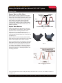
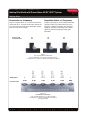
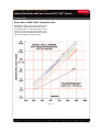
1
APPLICATION
W A V E F O R M
C O N T R O L
T E C H N O L O G Y
T M
Making Fillet Welds with Power Wave AC/DC 1000™ System
Welding Guide
Now from Lincoln - the power
to increase productivity with
Power Wave technology!
Lincoln Power Wave technology
based upon the new Power Wave
AC/DC 1000™ power source
provides the opportunity to
significantly lower the cost of
making fillet welds and at the
same time, makes many of the
issues that cause weld defects
a thing of the past. In some
respects, the Power Wave AC/DC
1000™ describes both a new
generation of equipment and
a new technology for
controlled welding.
40% Increase in Travel Speed
5/16” (8mm) Horizontal Fillet Weld
5/32” (4mm) Dia. Electrode
525 Amperes (Both Welds)
Now, from a single power source
it is possible to choose the very
best type of arc characteristic for
the particular job at hand. The
Power Wave AC/DC 1000™
system allows the choice of the
appropriate voltage-current
relationship at the mere “flick
of a switch”.
a
d
v
a
n
t
a
g
e
s
CHOICE AT THE “FLICK OF A SWITCH”
• Constant current (sometimes referred to as variable voltage).
• Constant voltage.
• Square Wave AC.
UNLIMITED AC OUTPUT TAILORING
• Choice of AC frequency (from 10 Hz to 100 Hz).
• Wave balance control to allow more or less DC
positive component.
• Offsetting the AC wave to change the magnitude of the
negative or positive component.
REDUCTION IN DEFECTS
• Virtual elimination of arc-striking problems.
• Virtual elimination of arc blow.
LOWER COSTS
• Documented productivity increases over conventional
submerged arc welding.
Patented. This product is protected by one or more of the following United States patents: 6,809,292;
6,795,778; 6,700,097; 6,697,701; 6,683,278; 6,660,966; 6,600,134; 6,683,278; 6,596,570; 6,570,130;
6,536,660; 6,489,952; 6,472,634; 6,636,776; 6,486,439; 6,441,342; 6,365,874; 6,291,798; 6,207,929;
6,111,216; 4,927,041; 4,861,965 and other pending U.S. patents. Similar patents are maintained in
other countries.
T
h
e
f
u
t
u
r
e
o
f
w
e
l
d
© Copyright 2005 The Lincoln Electric Company. All rights reserved.
i
n
g
i
s
h
e
r
e
.
NX-3.50 5/05
®
W A V E F O R M
C O N T R O L
T E C H N O L O G Y
T M
APPLICATION
Making Fillet Welds with Power Wave AC/DC 1000™ System
2/10
Welding Guide
DC welding has almost always been the preferred
choice for producing submerged arc welds. Some of
these reasons are:
contaminants, organic and/or inorganic contaminants
in or on the steel and greater potential for slag
entrapment because of the larger and “colder” weld
puddle. DC negative has always been the method of
choice for welding off-analysis steel or dirty steel
where it is desirable to have minimum dilution. But
with Power Wave AC/DC 1000™ technology, this is
no longer the best option. The Power Wave AC/DC
1000™ provides the capability of easily using the best
welding mode for the job at hand.
1. Lowest capital cost for equipment.
2. Greater arc stability than with AC.
3. Virtual elimination of arc striking problems.
4. Power issues (single phase vs. three phase
balanced power)
While DC negative may offer the highest deposit rate
per ampere, it is seldom used for automatic welding
that must meet stringent code requirements. This is
because DC negative is more prone to magnetic arc
interference (arc blow), porosity resulting from
Understanding Power Wave AC/DC 1000™
To fully understand the potential for possible
productivity gains using the Power Wave AC/DC
1000™ system, understanding the major AC
components and what they contribute is helpful.
The major components consist of:
1. Square wave (vs. a conventional sine wave)
2. Square wave balance
3. Square wave offset
4. Square wave frequency
DC+
527 Amps
Figure 1 shows photographs of two 5/16” (8mm)
horizontal fillet welds1. One is made using a good
DC+ procedure and one using a square wave 25%
balanced, (-)10% offset and 30 Hz. Both are excellent
fillets but the square wave procedure is forty percent
faster! Note that the amperage used is virtually the
same, 520 vs. 527 amperes.
1
AC/DC
520 Amps
Figure 1
40% faster travel speeds by using Power Wave AC/DC
1000™ Square Wave procedures over DC+ procedures.
These welds comply with the geometry requirements for leg and throat dimensions of all AWS codes.
T
h
e
f
u
t
u
r
e
o
f
w
e
l
d
i
n
g
i
s
h
e
r
e
.
®
W A V E F O R M
C O N T R O L
T E C H N O L O G Y
T M
APPLICATION
Making Fillet Welds with Power Wave AC/DC 1000™ System
3/10
Welding Guide
SINE WAVE
TRANSITION
REGION
Square Wave vs. Sine Wave
SQUARE WAVE
TRANSITION
REGION
Figure 2 shows one cycle of a true 60 Hz sine wave
with a square wave superimposed upon it. Note that
while the rms2 value and the peak values are the same
for both waves, the transition time for peak-to-peak is
much shorter for the square wave. The transition
period is what has always caused instability with
conventional AC welding but with the rapid transition
associated with the Power Wave AC/DC 1000™, arc
stability is increased.
+ VOLTS
0
- VOLTS
1 CYCLE
1/60 SECOND
Square Wave Balance
60 Hz SINE WAVE vs 60 Hz SQUARE WAVE
Figure 2
Square wave balance can allow the arc to act more
as a DC negative or DC positive arc, thus increasing
deposition rate or increasing penetration. This is
always expressed as a percentage of the DC +
component. i.e., (25% Balance means that only 25%
of the cycle will be positive while 75% of the cycle will
be negative, etc.)
Figure 3 shows two 3/8” (10mm) flat positioned fillet
welds. Both were made at 814 amperes but the square
wave AC 25% balance wave is made 17% faster.
DC+
Figure 4 graphically shows the significance that square
wave balance can and does play. Note that only 25%
of the time is the arc positive while 75% of the time
it is negative. This flexibility can be used to tailor the
arc to achieve best results by increasing deposition,
decreasing penetration or decreasing deposition and
increasing penetration.
AC 25% Balanced
Figure 3
Figure 4
2
Rms: root-mean-square value of current or voltage. For example, when someone refers to, “110 volts,” this is actually an rms value as is
“30 volts AC”, etc.
T
h
e
f
u
t
u
r
e
o
f
w
e
l
d
i
n
g
i
s
h
e
r
e
.
®
W A V E F O R M
C O N T R O L
T E C H N O L O G Y
T M
APPLICATION
Making Fillet Welds with Power Wave AC/DC 1000™ System
4/10
Welding Guide
Square Wave Offset Effect
Offset is expressed as a percentage between -25%
and +25% of the rms2 value that is kept positive or
negative. In other words, -25% means the normal
positive component of each cycle is held to 25% of
the normal rms value and the negative component
becomes 75%. In some respects, when offset is
adjusted to maximum values, the arc action almost
becomes analogous to that of a pulsed arc. Negative
values contribute to increasing deposition to levels
closely approaching the values obtainable with DC
negative welding. See Figure 5.
Square Wave - Normal Curve
50% Positive
0
50% Negative
1 CYCLE
1/60 SECOND
Square Wave - Current Offset
Figure 5
Comparison of offset vs normal balanced wave
Figure 6 shows two welds: the same 3/8” (10mm) flat
position fillet as Figure 3, but this time made using a
setting of 25% balance, (-)10% offset. Note that this
results in an additional gain of 12% in travel speed!
This is a net gain of 29% over DC+.
The increased deposits possible using a combination
of wave balance and wave offset may raise the
question about root penetration. While at present the
major welding codes do not allow sizing a fillet weld
based on root penetration, some producers of
proprietary products do. Figure 7 shows the depth of
penetration as compared to DC+ for a number of
settings. This shows a variation of only .05” (1.3mm) in
penetration, a variation of nine to ten percent. All of
the welds were made when the plate was at room
temperature and at 54.25Kj heat input.
Mode
DC+
Penetration-mm
5.53
Total
Amps
Total
Amps
Square Wave - Negative Offset
DC+
SW AC with Offset
AC 25% Balance
(-)10% Offset
Figure 6
Square Wave
Balanced
SW AC
25% Balanced
SW AC
25% Balanced
(-) 10% Offset
SW AC
25% Balanced
(-) 20% Offset
4.06
4.06
4.02
4.43
Figure 7
Penetration vs. Various Modes
All welds made using 5/32” (4mm) Diameter Electrode
525 Amperes, 31 Volts, 1.25” (31.8mm) ESO
18 ipm (457.2mm/min) Travel Speed
54.25 Kj Heat Input
T
h
e
f
u
t
u
r
e
o
f
w
e
l
d
i
n
g
i
s
h
e
r
e
.
®
W A V E F O R M
C O N T R O L
T E C H N O L O G Y
T M
APPLICATION
Making Fillet Welds with Power Wave AC/DC 1000™ System
5/10
Welding Guide
Square Wave Frequency
While frequency is historically accepted to be fifty
or sixty hertz, the Power Wave AC/DC 1000™ can
function at any chosen frequency between zero (DC)
and 100 hertz. Frequency can play an important role
in a specific welding procedure. Relative to a “normal”
sixty hertz, deposition rates can be slightly increased
or decreased as can penetration. Frequency alters
the total time for the arc to be at peak values. As the
frequency decreases, more time is available at peak
value and – more importantly – less time is spent in
the transition region. The converse occurs as
frequency is increased. Figure 8 (frequency effect)
illustrates this by showing what occurs during one
complete cycle.
As the frequency of the AC wave is altered, the
amount of time spent at peak current and voltage
values and the amount of time spent transitioning
from positive to negative values also changes.
Figure 8
Conventional sine waves (in red) are superimposed
schematically with Power Wave square waves to illustrate
the frequency effect. The voltage and current values are
identical for all three curves.
In general, as the frequency is lowered, more time is
spent at peak values and less time transitioning. As
the frequency is increased, the opposite occurs.
This can be of considerable help when making fillet
welds between thick and thin members in reducing
burn-through and undercut resulting from overheating
the thinner member, as might be the case when
welding stiffeners to girder web plates. This is further
illustrated in Figure 10, (Penetration vs Frequency).
T
h
e
f
u
t
u
r
e
o
f
w
e
l
d
i
n
g
i
s
h
e
r
e
.
®
W A V E F O R M
C O N T R O L
T E C H N O L O G Y
T M
APPLICATION
Making Fillet Welds with Power Wave AC/DC 1000™ System
6/10
Welding Guide
Penetration vs. Frequency
Deposition Rates vs. Frequency
Figure 9 compares three .31” (7.9mm) horizontal fillet
welds made at 10, 70 and 90 Hz. All were made at the
same heat input and travel speed. Penetration ranges
from 2.1mm to 3.2mm in depth.
Frequency also plays a role in total deposition rate.
Deposition rates may increase about 6% as the
frequency is lowered. Deposition rate decreases
slightly as frequency is increased. This could be
significant, when producing large single pass
fillet welds.
Frequency-Hz
10
70
90
Penetration-mm
2.5
3.2
2.1
DC+
SW AC 25% BAL
(-) 10% OFFSET
20 Hz
SW AC 25% BAL
(-) 10% OFFSET
40 Hz
SW AC 25% BAL
(-) 10% OFFSET
70 Hz
SW AC 25% BAL
(-) 10% OFFSET
80 Hz
DC-
Figure 9
5/32” (4.0mm) Diameter Electrode
AC 25% Balanced, (-)10% Offset, Hz (shown above)
525 Amperes, 1.0 (25mm), 21 ipm (827mm/min) Travel Speed
5.40
3.83
3.91
3.87
4.10
4.02
Welding Mode
Penetration-mm
Figure 10
Penetration vs Frequency
5/32” (4.0mm) Electrode, 1.25” (31.8mm) ESO
526 Amperes, 31 Volts, 18 ipm (457mm/min) Travel
54.4 Kj Heat Input
T
h
e
f
u
t
u
r
e
o
f
w
e
l
d
i
n
g
i
s
h
e
r
e
.
®
W A V E F O R M
C O N T R O L
T E C H N O L O G Y
T M
APPLICATION
Making Fillet Welds with Power Wave AC/DC 1000™ System
7/10
Welding Guide
Power Wave AC/DC 1000™ Deposition Rate
Illustrating the ability of Power Wave AC/DC 1000™
technology to significantly increase fillet-welding
productivity, Figure 11 shows the deposition rate vs.
amperes for 5/32” (4mm) diameter electrode. This
figure can be used to predict the increased deposit
rate while maintaining a constant current.
Figure 11
T
h
e
f
u
t
u
r
e
o
f
w
e
l
d
i
n
g
i
s
h
e
r
e
.
®
W A V E F O R M
C O N T R O L
T E C H N O L O G Y
T M
APPLICATION
Making Fillet Welds with Power Wave AC/DC 1000™ System
8/10
Welding Guide
Some Fillet Weld Results`
A number of fillet welds made with the Power Wave
AC/DC 1000™ are shown as examples. All of these
welds comply with the AWS D1.1 Structural Steel
Code and the AWS D1.5 Bridge Code and those
codes that clone or refer to the AWS Codes.
All fillet welds conform to the acceptable size and
gauge size requirements of the code.There has been
no intent to match any specific mechanical properties,
however, the welding consumables used to produce
these welds are commonly used.
Figure 12
The weld on the left is DC+, 15 ipm travel.
The weld on the right is AC Balanced 25%, (-) 10% offset,
30 Hz., 21 ipm travel.
Figure 12: Horizontal, 5/16” (8mm) fillet welds, shows
an increase of 40% in travel speed over DC+. Both
welds made with 5/32” (4mm) diameter electrode at
527 amperes.
Figure 13: Flat positioned 1/2” (13mm) fillet welds
show an increase of 44% in travel speed over DC+.
Both welds made using 3/16” (4.8mm) diameter
electrode at 885 amperes.
Figure 13
The weld on the left is with DC+, at 10.4 ipm travel.
The weld on the right is with AC 25% Balanced,
(-)20% Offset, 30Hz, at 15 ipm.
Figure 14: Horizontal 1/4” (6mm) fillet welds, with an
increase of 32% in travel speed over DC+.
Figure 14
The weld on the left is with DC+.
The weld on the right is with AC 25% Balanced,
(-)10% Offset, 60Hz.
T
h
e
f
u
t
u
r
e
o
f
w
e
l
d
i
n
g
i
s
h
e
r
e
.
®
W A V E F O R M
C O N T R O L
T E C H N O L O G Y
T M
APPLICATION
Making Fillet Welds with Power Wave AC/DC 1000™ System
9/10
Welding Guide
CONVERTING TO A POWER WAVE PROCEDURE
An easy approach to making a conversion to a Power
Wave AC/DC 1000™ procedure is to use this table as
a general guide and follow these steps:
1. Start with the existing variable voltage DC positive
procedure as the reference procedure.
% Positive
% Offset
Deposition
Rate
Arc Volt
Change
2. Move to AC balanced square wave mode and use
the reference travel speed and voltage.
100 DC+
NA
1.0
Reference
3. Adjust frequency from 30 to 90 Hz. (stop if the
current value begins to drop).
50
0
1.11
+0
4. Shift the AC balance to 25%,
25
0
1.20
+3
25
-10
1.30
+4
0 DC-
NA
1.35
+3
a. Increase voltage 2-3 volts,
b. Increase travel speed 1.2 times reference value.
5. Add 5 to 10% negative (minus) offset,
a. Increase voltage an additional 1-2 volts,
b. Raise travel speed to 1.3 times reference speed.
This will yield a good starting point for converting a DC+
fillet welding procedure. Fine tuning these steps will
yield the maximum increase with equal or improved
weld appearance.
Easy Welding Procedure Setup
The Power Wave AC/DC 1000™ system is the easiest
system ever produced when it comes to changing from
one welding procedure to another.
• No need to move (change) welding cables even when
changing polarity or changing from constant current to
constant voltage.
• No need to internally reconnect power carrying taps or
bus bars, hence, in many instances no need for a
maintenance electrician.
• Control all output functions on the control panel.
• Fully supported by Lincoln’s Power Wave Submerged
Arc Utilities software where demanding applications
require activity reporting or even remote procedure
verification (see Nextweld NX3.20 brochure).The heart
of the system is the Power Wave AC/DC 1000™ featuring:
• Balanced input line-draw even when welding with AC.
• High 86% electrical efficiency contributes to keeping
energy charges low.
• 95% power factor assures minimizing excess ampere
draw from the supply lines.
• Continuous output rating 1000 amperes assures the
system is ready-to-go full time.
T
h
e
f
u
t
u
r
e
o
f
w
e
l
d
i
n
g
i
s
h
e
r
e
.
®
W A V E F O R M
C O N T R O L
T E C H N O L O G Y
T M
APPLICATION
Making Fillet Welds with Power Wave AC/DC 1000™ System
10/10
Welding Guide
Power Wave AC/DC 1000™
System Cost Recapture Analysis*
WHAT IS NEXTWELD?
The challenges facing industrial
fabricators today are increasingly
difficult. Rising labor, material, and
energy costs, intense domestic and
global competition,
a dwindling pool of
skilled workers,
more stringent and
specific quality
demands.
Example: Using a burden charge of 40.00 $/Hr., an operating factor of 40%
and the need to produce either of the following welds:
Producing 1/2” (13mm) flat positioned fillet welds
Present weld: DC+, 885 amps, 10.40 in/min . . . . . . . . . . . . . . . . . . . . . . . . . . .1.92 $/Ft
Power Wave Weld: 885 amps (25% bal, -20% off, 30Hz), 14.2 in/min . . . . . . .1.41 $/Ft
Dollar Saving per Foot of Weld . . . . . . . . . . . . . . . . . . . . . . . . . . . . . . . . .0.50 $/Ft
Through our
commitment to
extensive research
and investments in
product
development,
Lincoln Electric has
established an industry benchmark for
applying technology to improve the
quality, lower the cost and enhance the
performance of arc welding processes.
Advancements in power electronics,
digital communications and Waveform
Control Technology™ are the foundation
for many of the improvements.
Annual Saving based upon a 2000 hour-year . . . . . . . . . . . . . . . . . . . . . . . . . .$28,400
Less than 11 months to recapture the cost of the
Power Wave AC/DC 1000™ and returns a 36.5 percent
increase in production capacity!
Producing 5/16” (8mm) horizontal fillet welds
Present weld: DC+, 525 amps, 15.0 in/min . . . . . . . . . . . . . . . . . . . . . . . . . . . .1.33 $/Ft
Power Wave Weld: 525 amps (25% bal, -10% off, 30Hz), 21.0 in/min . . . . . . .0.95 $/Ft
Dollar Saving per Foot of Weld . . . . . . . . . . . . . . . . . . . . . . . . . . . . . . . . .0.38 $/Ft
Annual Saving based upon a 2000 hour-year . . . . . . . . . . . . . . . . . . . . . . . . . .$31,920
NEXTWELD brings you a series of
Process, Technology, Application and
Success Story documents like this one.
NEXTWELD explains how technologies,
products, processes and applications are
linked together to answer the important
questions that all businesses face:
Less than 10 months to recapture the cost of the
Power Wave AC/DC 1000™ and with a 40 percent
increase in production capacity!
To maintain or improve your competitive edge, contact the
nearest Lincoln Electric Technical Sales Representative to
discuss and start the process toward lower welding costs
and increased productivity.
• How can we work faster, smarter,
more efficiently?
• How can we get equipment and
*Based upon present cost of an equipment setup that includes Power Wave AC/DC 1000™,
Power Feed 10A Controller, Travel Carriage, and essential accessory items including vertical and
horizontal adjusters, contact nozzle and wire reel. Prices for other packages will vary. The cost of
other equipment packages may alter the time to recapture the purchase cost.
people to perform in ways they’ve
never had to before?
• How do we stay competitive?
Customer Assistance Policy
NEXTWELD is the future of welding but
its benefits are available to you today.
Ask your Lincoln Electric representative
how to improve the flexibility, efficiency
and quality of your welding operations to
reduce your cost of fabrication.
The business of The Lincoln Electric Company is manufacturing and selling high quality welding equipment,
consumables, and cutting equipment. Our challenge is to meet the needs of our customer and to exceed
their expectations. On occasion, purchasers may ask Lincoln Electric for advice or information about their
use of our products. We respond to our customers based on the best information in our possession at that
time. Lincoln Electric is not in a position to warrant or guarantee such advice, and assumes no liability, with
respect to such information or advice. We expressly disclaim any warranty of any kind, including any
warranty of fitness for any customer’s particular purpose, with respect to such information or advice. As a
matter of practical consideration, we also cannot assume any responsibility for updating or correcting any
such information or advice once it has been given, nor does the provision of information or advice create,
expand or alter any warranty with respect to the sale of our products.
Lincoln Electric is a responsive manufacturer, but the selection and use of specific products sold by
Lincoln Electric is solely within the control of, and remains the sole responsibility of the customer. Many
variables beyond the control of Lincoln Electric affect the results obtained in applying these types of
fabrication methods and service requirement.
THE LINCOLN ELECTRIC COMPANY
www.lincolnelectric.com
1.216.481.8100
Subject to change - This information is accurate to the best of our knowledge at the time of printing.
Please refer to www.lincolnelectric.com for any updated information.
T
h
e
f
u
t
u
r
e
o
f
w
e
l
d
i
n
g
i
s
h
e
r
e
.
®