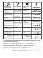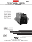
1
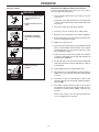
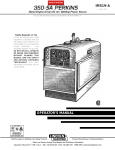
RETURN TO MAIN MENU
MAGNUM SG CONTROL MODULE
™
IM398
February, 2000
For use with machines having Code Numbers:
Safety Depends on You
Lincoln arc welding and cutting
equipment is designed and built
with safety in mind. However, your
overall safety can be increased by
proper installation ... and thoughtful operation on your part. DO
NOT INSTALL, OPERATE OR
REPAIR THIS EQUIPMENT
WITHOUT READING THIS
MANUAL AND THE SAFETY
PRECAUTIONS CONTAINED
THROUGHOUT. And, most
importantly, think before you act
and be careful.
Date of Purchase:
Serial Number:
Code Number:
Model:
Where Purchased:
OPERATOR’S MANUAL
• World's Leader in Welding and Cutting Products •
• Sales and Service through Subsidiaries and Distributors Worldwide •
Cleveland, Ohio 44117-1199 U.S.A. TEL: 216.481.8100 FAX: 216.486.1751 WEB SITE: www.lincolnelectric.com
SAFETY
WARNING
CALIFORNIA PROPOSITION 65 WARNINGS
The engine exhaust from this product contains
chemicals known to the State of California to cause
cancer, birth defects, or other reproductive harm.
The Above For Gasoline Engines
Diesel engine exhaust and some of its constituents
are known to the State of California to cause cancer, birth defects, and other reproductive harm.
The Above For Diesel Engines
ARC WELDING CAN BE HAZARDOUS. PROTECT YOURSELF AND OTHERS FROM POSSIBLE SERIOUS INJURY OR DEATH.
KEEP CHILDREN AWAY. PACEMAKER WEARERS SHOULD CONSULT WITH THEIR DOCTOR BEFORE OPERATING.
Read and understand the following safety highlights. For additional safety information, it is strongly recommended that you
purchase a copy of “Safety in Welding & Cutting - ANSI Standard Z49.1” from the American Welding Society, P.O. Box
351040, Miami, Florida 33135 or CSA Standard W117.2-1974. A Free copy of “Arc Welding Safety” booklet E205 is available
from the Lincoln Electric Company, 22801 St. Clair Avenue, Cleveland, Ohio 44117-1199.
BE SURE THAT ALL INSTALLATION, OPERATION, MAINTENANCE AND REPAIR PROCEDURES ARE
PERFORMED ONLY BY QUALIFIED INDIVIDUALS.
FOR ENGINE
powered equipment.
1.h. To avoid scalding, do not remove the
radiator pressure cap when the engine is
hot.
1.a. Turn the engine off before troubleshooting and maintenance
work unless the maintenance work requires it to be running.
____________________________________________________
1.b. Operate engines in open, well-ventilated
areas or vent the engine exhaust fumes
outdoors.
ELECTRIC AND
MAGNETIC FIELDS
may be dangerous
____________________________________________________
1.c. Do not add the fuel near an open flame
welding arc or when the engine is running.
Stop the engine and allow it to cool before
refueling to prevent spilled fuel from vaporizing on contact with hot engine parts and
igniting. Do not spill fuel when filling tank. If
fuel is spilled, wipe it up and do not start
engine until fumes have been eliminated.
____________________________________________________
1.d. Keep all equipment safety guards, covers and devices in
position and in good repair.Keep hands, hair, clothing and
tools away from V-belts, gears, fans and all other moving
parts when starting, operating or repairing equipment.
____________________________________________________
2.a. Electric current flowing through any conductor causes
localized Electric and Magnetic Fields (EMF). Welding
current creates EMF fields around welding cables and
welding machines
2.b. EMF fields may interfere with some pacemakers, and
welders having a pacemaker should consult their physician
before welding.
2.c. Exposure to EMF fields in welding may have other health
effects which are now not known.
2.d. All welders should use the following procedures in order to
minimize exposure to EMF fields from the welding circuit:
1.e. In some cases it may be necessary to remove safety
guards to perform required maintenance. Remove
guards only when necessary and replace them when the
maintenance requiring their removal is complete.
Always use the greatest care when working near moving
parts.
___________________________________________________
1.f. Do not put your hands near the engine fan.
Do not attempt to override the governor or
idler by pushing on the throttle control rods
while the engine is running.
2.d.1. Route the electrode and work cables together - Secure
them with tape when possible.
2.d.2. Never coil the electrode lead around your body.
2.d.3. Do not place your body between the electrode and
work cables. If the electrode cable is on your right
side, the work cable should also be on your right side.
2.d.4. Connect the work cable to the workpiece as close as
possible to the area being welded.
___________________________________________________
1.g. To prevent accidentally starting gasoline engines while
turning the engine or welding generator during maintenance
work, disconnect the spark plug wires, distributor cap or
magneto wire as appropriate.
2.d.5. Do not work next to welding power source.
Mar ‘95
-2-
SAFETY
ARC RAYS can burn.
ELECTRIC SHOCK can
kill.
4.a. Use a shield with the proper filter and cover
plates to protect your eyes from sparks and
the rays of the arc when welding or observing
open arc welding. Headshield and filter lens
should conform to ANSI Z87. I standards.
3.a. The electrode and work (or ground) circuits
are electrically “hot” when the welder is on.
Do not touch these “hot” parts with your bare
skin or wet clothing. Wear dry, hole-free
gloves to insulate hands.
4.b. Use suitable clothing made from durable flame-resistant
material to protect your skin and that of your helpers from
the arc rays.
3.b. Insulate yourself from work and ground using dry insulation.
Make certain the insulation is large enough to cover your full
area of physical contact with work and ground.
4.c. Protect other nearby personnel with suitable, non-flammable
screening and/or warn them not to watch the arc nor expose
themselves to the arc rays or to hot spatter or metal.
In addition to the normal safety precautions, if welding
must be performed under electrically hazardous
conditions (in damp locations or while wearing wet
clothing; on metal structures such as floors, gratings or
scaffolds; when in cramped positions such as sitting,
kneeling or lying, if there is a high risk of unavoidable or
accidental contact with the workpiece or ground) use
the following equipment:
• Semiautomatic DC Constant Voltage (Wire) Welder.
• DC Manual (Stick) Welder.
• AC Welder with Reduced Voltage Control.
FUMES AND GASES
can be dangerous.
5.a. Welding may produce fumes and gases
hazardous to health. Avoid breathing these
fumes and gases.When welding, keep
your head out of the fume. Use enough
ventilation and/or exhaust at the arc to keep
fumes and gases away from the breathing zone. When
welding with electrodes which require special
ventilation such as stainless or hard facing (see
instructions on container or MSDS) or on lead or
cadmium plated steel and other metals or coatings
which produce highly toxic fumes, keep exposure as
low as possible and below Threshold Limit Values (TLV)
using local exhaust or mechanical ventilation. In
confined spaces or in some circumstances, outdoors, a
respirator may be required. Additional precautions are
also required when welding on galvanized steel.
3.c. In semiautomatic or automatic wire welding, the electrode,
electrode reel, welding head, nozzle or semiautomatic
welding gun are also electrically “hot”.
3.d. Always be sure the work cable makes a good electrical
connection with the metal being welded. The connection
should be as close as possible to the area being welded.
3.e. Ground the work or metal to be welded to a good electrical
(earth) ground.
5.b. Do not weld in locations near chlorinated hydrocarbon vapors
coming from degreasing, cleaning or spraying operations.
The heat and rays of the arc can react with solvent vapors to
form phosgene, a highly toxic gas, and other irritating
products.
3.f. Maintain the electrode holder, work clamp, welding cable and
welding machine in good, safe operating condition. Replace
damaged insulation.
3.g. Never dip the electrode in water for cooling.
5.c. Shielding gases used for arc welding can displace air and
cause injury or death. Always use enough ventilation,
especially in confined areas, to insure breathing air is safe.
3.h. Never simultaneously touch electrically “hot” parts of
electrode holders connected to two welders because voltage
between the two can be the total of the open circuit voltage
of both welders.
5.d. Read and understand the manufacturer’s instructions for this
equipment and the consumables to be used, including the
material safety data sheet (MSDS) and follow your
employer’s safety practices. MSDS forms are available from
your welding distributor or from the manufacturer.
3.i. When working above floor level, use a safety belt to protect
yourself from a fall should you get a shock.
3.j. Also see Items 6.c. and 8.
5.e. Also see item 1.b.
-3-
Mar ‘95
SAFETY
WELDING SPARKS can
cause fire or explosion.
CYLINDER may explode
if damaged.
6.a. Remove fire hazards from the welding area.
If this is not possible, cover them to prevent
the welding sparks from starting a fire.
Remember that welding sparks and hot
materials from welding can easily go through small cracks
and openings to adjacent areas. Avoid welding near
hydraulic lines. Have a fire extinguisher readily available.
7.a. Use only compressed gas cylinders
containing the correct shielding gas for the
process used and properly operating
regulators designed for the gas and
pressure used. All hoses, fittings, etc. should be suitable for
the application and maintained in good condition.
7.b. Always keep cylinders in an upright position securely
chained to an undercarriage or fixed support.
6.b. Where compressed gases are to be used at the job site,
special precautions should be used to prevent hazardous
situations. Refer to “Safety in Welding and Cutting” (ANSI
Standard Z49.1) and the operating information for the
equipment being used.
7.c. Cylinders should be located:
• Away from areas where they may be struck or subjected to
physical damage.
6.c. When not welding, make certain no part of the electrode
circuit is touching the work or ground. Accidental contact
can cause overheating and create a fire hazard.
• A safe distance from arc welding or cutting operations and
any other source of heat, sparks, or flame.
7.d. Never allow the electrode, electrode holder or any other
electrically “hot” parts to touch a cylinder.
6.d. Do not heat, cut or weld tanks, drums or containers until the
proper steps have been taken to insure that such procedures
will not cause flammable or toxic vapors from substances
inside. They can cause an explosion even though they have
been “cleaned”. For information, purchase “Recommended
Safe Practices for the Preparation for Welding and Cutting of
Containers and Piping That Have Held Hazardous
Substances”, AWS F4.1 from the American Welding Society
(see address above).
7.e. Keep your head and face away from the cylinder valve outlet
when opening the cylinder valve.
7.f. Valve protection caps should always be in place and hand
tight except when the cylinder is in use or connected for
use.
7.g. Read and follow the instructions on compressed gas
cylinders, associated equipment, and CGA publication P-l,
“Precautions for Safe Handling of Compressed Gases in
Cylinders,” available from the Compressed Gas Association
1235 Jefferson Davis Highway, Arlington, VA 22202.
6.e. Vent hollow castings or containers before heating, cutting or
welding. They may explode.
6.f. Sparks and spatter are thrown from the welding arc. Wear oil
free protective garments such as leather gloves, heavy shirt,
cuffless trousers, high shoes and a cap over your hair. Wear
ear plugs when welding out of position or in confined places.
Always wear safety glasses with side shields when in a
welding area.
FOR ELECTRICALLY
powered equipment.
6.g. Connect the work cable to the work as close to the welding
area as practical. Work cables connected to the building
framework or other locations away from the welding area
increase the possibility of the welding current passing
through lifting chains, crane cables or other alternate circuits. This can create fire hazards or overheat lifting chains
or cables until they fail.
8.a. Turn off input power using the disconnect
switch at the fuse box before working on
the equipment.
8.b. Install equipment in accordance with the U.S. National
Electrical Code, all local codes and the manufacturer’s
recommendations.
6.h. Also see item 1.c.
8.c. Ground the equipment in accordance with the U.S. National
Electrical Code and the manufacturer’s recommendations.
Mar ‘95
-4-
SAFETY
zones où l’on pique le laitier.
PRÉCAUTIONS DE SÛRETÉ
6. Eloigner les matériaux inflammables ou les recouvrir afin de
prévenir tout risque d’incendie dû aux étincelles.
Pour votre propre protection lire et observer toutes les instructions
et les précautions de sûreté specifiques qui parraissent dans ce
manuel aussi bien que les précautions de sûreté générales suivantes:
7. Quand on ne soude pas, poser la pince à une endroit isolé de
la masse. Un court-circuit accidental peut provoquer un
échauffement et un risque d’incendie.
Sûreté Pour Soudage A L’Arc
1. Protegez-vous contre la secousse électrique:
8. S’assurer que la masse est connectée le plus prés possible
de la zone de travail qu’il est pratique de le faire. Si on place
la masse sur la charpente de la construction ou d’autres
endroits éloignés de la zone de travail, on augmente le risque
de voir passer le courant de soudage par les chaines de levage, câbles de grue, ou autres circuits. Cela peut provoquer
des risques d’incendie ou d’echauffement des chaines et des
câbles jusqu’à ce qu’ils se rompent.
a. Les circuits à l’électrode et à la piéce sont sous tension
quand la machine à souder est en marche. Eviter toujours
tout contact entre les parties sous tension et la peau nue
ou les vétements mouillés. Porter des gants secs et sans
trous pour isoler les mains.
b. Faire trés attention de bien s’isoler de la masse quand on
soude dans des endroits humides, ou sur un plancher
metallique ou des grilles metalliques, principalement dans
les positions assis ou couché pour lesquelles une grande
partie du corps peut être en contact avec la masse.
c. Maintenir le porte-électrode, la pince de masse, le câble
de soudage et la machine à souder en bon et sûr état
defonctionnement.
d.Ne jamais plonger le porte-électrode dans l’eau pour le
refroidir.
e. Ne jamais toucher simultanément les parties sous tension
des porte-électrodes connectés à deux machines à souder
parce que la tension entre les deux pinces peut être le
total de la tension à vide des deux machines.
f. Si on utilise la machine à souder comme une source de
courant pour soudage semi-automatique, ces precautions
pour le porte-électrode s’applicuent aussi au pistolet de
soudage.
9. Assurer une ventilation suffisante dans la zone de soudage.
Ceci est particuliérement important pour le soudage de tôles
galvanisées plombées, ou cadmiées ou tout autre métal qui
produit des fumeés toxiques.
10. Ne pas souder en présence de vapeurs de chlore provenant
d’opérations de dégraissage, nettoyage ou pistolage. La
chaleur ou les rayons de l’arc peuvent réagir avec les vapeurs
du solvant pour produire du phosgéne (gas fortement toxique)
ou autres produits irritants.
11. Pour obtenir de plus amples renseignements sur la sûreté,
voir le code “Code for safety in welding and cutting” CSA
Standard W 117.2-1974.
2. Dans le cas de travail au dessus du niveau du sol, se protéger
contre les chutes dans le cas ou on recoit un choc. Ne jamais
enrouler le câble-électrode autour de n’importe quelle partie
du corps.
PRÉCAUTIONS DE SÛRETÉ POUR
LES MACHINES À SOUDER À
TRANSFORMATEUR ET À
REDRESSEUR
3. Un coup d’arc peut être plus sévère qu’un coup de soliel,
donc:
a. Utiliser un bon masque avec un verre filtrant approprié
ainsi qu’un verre blanc afin de se protéger les yeux du rayonnement de l’arc et des projections quand on soude ou
quand on regarde l’arc.
b. Porter des vêtements convenables afin de protéger la
peau de soudeur et des aides contre le rayonnement de
l‘arc.
c. Protéger l’autre personnel travaillant à proximité au
soudage à l’aide d’écrans appropriés et non-inflammables.
1. Relier à la terre le chassis du poste conformement au code de
l’électricité et aux recommendations du fabricant. Le dispositif
de montage ou la piece à souder doit être branché à une
bonne mise à la terre.
2. Autant que possible, I’installation et l’entretien du poste seront
effectués par un électricien qualifié.
3. Avant de faires des travaux à l’interieur de poste, la debrancher à l’interrupteur à la boite de fusibles.
4. Des gouttes de laitier en fusion sont émises de l’arc de
soudage. Se protéger avec des vêtements de protection libres
de l’huile, tels que les gants en cuir, chemise épaisse, pantalons sans revers, et chaussures montantes.
4. Garder tous les couvercles et dispositifs de sûreté à leur
place.
5. Toujours porter des lunettes de sécurité dans la zone de
soudage. Utiliser des lunettes avec écrans lateraux dans les
Mar. ‘93
-5-
Thank You
for selecting a QUALITY product by Lincoln Electric. We want you
to take pride in operating this Lincoln Electric Company product
••• as much pride as we have in bringing this product to you!
Please Examine Carton and Equipment For Damage Immediately
When this equipment is shipped, title passes to the purchaser upon receipt by the carrier. Consequently, Claims
for material damaged in shipment must be made by the purchaser against the transportation company at the
time the shipment is received.
Please record your equipment identification information below for future reference. This information can be
found on your machine nameplate.
Model Name & Number _____________________________________
Code & Serial Number _____________________________________
Date of Purchase
_____________________________________
Whenever you request replacement parts for or information on this equipment always supply the information
you have recorded above.
Read this Operators Manual completely before attempting to use this equipment. Save this manual and keep it
handy for quick reference. Pay particular attention to the safety instructions we have provided for your protection.
The level of seriousness to be applied to each is explained below:
WARNING
This statement appears where the information must be followed exactly to avoid serious personal injury or
loss of life.
CAUTION
This statement appears where the information must be followed to avoid minor personal injury or damage to
this equipment.
-6-
TABLE OF CONTENTS
Page
SAFETY PRECAUTIONS . . . . . . . . . . . . . . . . . . . . . . . . . . . . . . . . . . . . . . . . . . . . . . . . . . . . . . .2-5
PRODUCT DESCRIPTION. . . . . . . . . . . . . . . . . . . . . . . . . . . . . . . . . . . . . . . . . . . . . . . . . . . . . . . .8
SPECIFICATIONS . . . . . . . . . . . . . . . . . . . . . . . . . . . . . . . . . . . . . . . . . . . . . . . . . . . . . . . . . . . . . .8
REQUIRED EQUIPMENT . . . . . . . . . . . . . . . . . . . . . . . . . . . . . . . . . . . . . . . . . . . . . . . . . . . . . . . .8
OPTIONAL ACCESSORIES . . . . . . . . . . . . . . . . . . . . . . . . . . . . . . . . . . . . . . . . . . . . . . . . . . . .8-10
INSTALLATION . . . . . . . . . . . . . . . . . . . . . . . . . . . . . . . . . . . . . . . . . . . . . . . . . . . . . . . . . . . . . . .11
Safety Precautions . . . . . . . . . . . . . . . . . . . . . . . . . . . . . . . . . . . . . . . . . . . . . . . . . . . . . . . . . .11
Unpacking the Control Module . . . . . . . . . . . . . . . . . . . . . . . . . . . . . . . . . . . . . . . . . . . . . . . . .11
Control Module Familiarization . . . . . . . . . . . . . . . . . . . . . . . . . . . . . . . . . . . . . . . . . . . . . . . . .11
Connection to Power Source . . . . . . . . . . . . . . . . . . . . . . . . . . . . . . . . . . . . . . . . . . . . . . . . . .12
Installation of K492-10 Input Cable to Power Sources with a Terminal Strip . . . . . . . . . . . .12
Installation of K493-10 Input Cable to Power Sources with a 14-pin Connector . . . . . . . . .12
Installation of K691-10 Input Cable with14-Pin Connector to 115V Plug . . . . . . . . . . . . . .13
Setting the Mode Switch on Rear Panel . . . . . . . . . . . . . . . . . . . . . . . . . . . . . . . . . . . . . . . . . .13
Connection to Spool Gun . . . . . . . . . . . . . . . . . . . . . . . . . . . . . . . . . . . . . . . . . . . . . . . . . . . . .14
Work Lead Connection . . . . . . . . . . . . . . . . . . . . . . . . . . . . . . . . . . . . . . . . . . . . . . . . . . . . . . .13
OPERATING INSTRUCTIONS . . . . . . . . . . . . . . . . . . . . . . . . . . . . . . . . . . . . . . . . . . . . . . . . . . . .15
Safety Precautions . . . . . . . . . . . . . . . . . . . . . . . . . . . . . . . . . . . . . . . . . . . . . . . . . . . . . . . . . .15
Initial Checkout of Magnum SG System Installation . . . . . . . . . . . . . . . . . . . . . . . . . . . . . . . . .15
Setting Gas Flow Rate on Gas Cylinder Regulator . . . . . . . . . . . . . . . . . . . . . . . . . . . . . . . . . .16
Setting Gas Preflow Time on Control Module . . . . . . . . . . . . . . . . . . . . . . . . . . . . . . . . . . . . . .16
Setting the Wire Speed . . . . . . . . . . . . . . . . . . . . . . . . . . . . . . . . . . . . . . . . . . . . . . . . . . . . . . .16
Setting Wire Speed When Using a K469 Spool Gun . . . . . . . . . . . . . . . . . . . . . . . . . . . . . .16
Setting Wire Speed When Using a K487 Spool Gun Having Remote Speed Control . . . . .16
Making a Weld . . . . . . . . . . . . . . . . . . . . . . . . . . . . . . . . . . . . . . . . . . . . . . . . . . . . . . . . . . . . . .16
MAINTENANCE . . . . . . . . . . . . . . . . . . . . . . . . . . . . . . . . . . . . . . . . . . . . . . . . . . . . . . . . . . . . . . .16
Safety Precautions . . . . . . . . . . . . . . . . . . . . . . . . . . . . . . . . . . . . . . . . . . . . . . . . . . . . . . . . . .16
Routine Maitenance . . . . . . . . . . . . . . . . . . . . . . . . . . . . . . . . . . . . . . . . . . . . . . . . . . . . . . . . .16
WIRING DIAGRAM . . . . . . . . . . . . . . . . . . . . . . . . . . . . . . . . . . . . . . . . . . . . . . . . . . . . . . . . . . . .17
PARTS LIST . . . . . . . . . . . . . . . . . . . . . . . . . . . . . . . . . . . . . . . . . . . . . . . . . . . . . . . . . .P198 Series
-7-
Specifications
Product Description
The Magnum SG Control Module is an interface between the
welding power source and the Magnum Spool Gun. The
Control Module and Spool Gun combination provide a system for
welding primarily with aluminum electrode wire using a constant voltage welding power source.
The Control Module provides control of both wire speed and
gas flow. It also provides connections from the welding power
cable, control cable, and gas hose from the power source and
gas cylinder regulator to the spool gun.
Model:
Magnum SG Control Module
Type:
K488
Power Requirements: Voltage
Current
Welding Current Rating:
Motor Output:
Preflow Time:
Contactor Circuit Output:
115 VAC, 50/60 Hz
0.5 amps maximum
250 amps at 60% duty cycle
5-28 VDC
0-1 second
Normally open relay contacts
(“Closure”) or 115 VAC; selectable
10.0 x 8.25 x 9.0 inches
(254 x 210 x 229mm)
13 Lbs. (5.9kg)
Dimensions, H* x W x D
*dimension includes handle
Weight
The Control Module will operate with any power source that
provides constant voltage welding output and has an output
contactor.
Required Equipment
To operate the Magnum SG Control Module, the following
equipment is required and ordered separately:
Optional Accessories
Several accessories are optionally available for use with the
K488 control module, and they are as follows:
1. Three 10 ft. (3.0m) input cable assemblies are available
and consist of control and electrode cables and gas line.
The proper input cable assembly must be ordered in addition to the control module; as none are included with the
control module:
Magnum Spool Gun
K487-25 or
K469-25 with K518
Adapter
A. K492-10 for use with Lincoln CV power sources
having terminal strip control connections (Lincoln
R3S, CV-400, and DC family machines). Can also
be used with non-Lincoln CV power sources.
Power Source
The Control Module will operate with any Lincoln CV or CV/CC
power sources, with many Lincoln engine-driven welders (see
the complete list at the end of this section), and with many
non-Lincoln type power sources.
B. K493-10 for use with Lincoln CV power sources
having 14-pin control cable connection (Lincoln CV
and CV-I series, Invertec V-200).
In general, power sources must have the following:
C. K691-10 for use with Lincoln engine-driven power
sources having 14-pin control cable connection
and/or 115VAC outlet.
1. A constant voltage (CV) type welding output.
2. Capability to supply 115 volt AC power to the control
module.
2. K473 Spool Gun Extension Cable. 25’ extension cable
extends distance between spool gun and K488 control
module.
3. Optional for “cold electrode” switched welding output: An
output contactor. It can be either of two types:
A. Switch closure: Internally-energized type actuated
by an external switch.
B. 115 VAC: Externally-energized type actuated by
115 volts AC supplied from the control module to
the power source.
A selector switch on the back of the control module is
used to select which of these two types of control circuit is
being used. It is imperative that this switch be set correctly
before attaching to the power source. See “Setting the
Mode Switch on Rear Panel” for more details.
3. K518 Adapter for K469 Spool Gun. Adapts K469 spool
gun to K488 Control Module or to K473 Extension Cable.
The control module is not required when connecting Magnum
spool guns to Lincoln models SP-150 or SP-200, which have
built-in wire feed control circuits. In addition, the Lincoln models
SP-250, SP-255, Wire-Matic 250, Wire-Matic 255 do not
require the control module when the optional K607-1 or K672-1
Spool Gun Adapter kit is installed, since these kits also provide
wire feed control circuits.
K492-10
K493-10
For convenience, here is a summary of needed equipment to
use the various combinations of available Magnum spool guns
and accessories:
-8-
ACCESSORIES
For Static (Transformer Type) Power Sources
Power
Source
Spool
Gun
SP-150
SP-200
SP-250/SP 250-I
& Wire-Matic 250
SP-255/SP 255-I
& Wire-Matic 255
CV Output Machine
with Contactor
K469-25
None
required
None
required
K518 Adapter
K607-1 Spool
Gun Adapter
Kit
K518 Adapter
K672-1 Spool
Gun Adapter
Kit
K518 Adapter
K488 Control Module
K492-10 Input Cable for
machines with terminal
strip -OR- K493-10
Input Cable for Lincoln
macines with 14-pin
connector
K469-25
with
K473
Extension
Cable
K518
Adapter
K516
Adapter
K518 Adapter
K517 Adapter
K518 Adapter
K607-1 Spool
Gun Adapter
Kit
(K473 requires
minor modification)
K518 Adapter
K672-1 Spool
Gun Adapter
Kit
same as above
K487-25
K516 Adapter
(No remote
WFS control)
K517 Adapter
(No remote
WFS control)
K607-1 Spool
Gun Adapter
Kit
K672-1 Spool
Gun Adapter
Kit
K488 Control Module
K492-10 Input Cable for
machines with terminal
strip -OR- K493-10
Input Cable for Lincoln
machines with 14-pin
connector
K487-25
with K473
Extension
Cable
K516 Adapter
(No remote
WFS control)
K517 Adapter
(No remote
WFS control)
K607-1 Spool
Gun Adapter
Kit
(K473 requires
minor modification)
K672-1 Spool
Gun Adapter
Kit
same as above
-9-
ACCESSORIES
For Rotating (Engine-Driven Type) Power Sources:
Machine*
Classic II
Classic II w/Wire Feeder Module
Classic III
Classic III w/Wire Feed Module
Classic IIID
Classic IIID w/Wire Feed Module
Commander 300
Commander 400 (Stick)
Commander 400 (Stick & Wire)
Ranger 10
Ranger 10LX (Incl. CSA)
Ranger 275
Ranger 300D
Ranger 300DLX
Ranger 8 (Incl. CSA & LPG)
Ranger 9 (Incl. CSA)
SA-250
SA-250 w/CV Adapter
SA-250 w/Wire Feed Module
350-SA
350-SA w/Wire Feed Module
SAE-350 w/CV Adapter
SAE-400 w/CV Adapter
SAE-400 WELD ‘N AIR w/CV Adapter
SAM-400
450 SAE w/CV Adapter
SAM-650
Weldanpower 150 AC/DC
Weldanpower 225 G7
Weldanpower 250 D10
Weldanpower 250 D10 PRO
Weldanpower 250 G9 PRO
Weldanpower G8000
14-pin
Amphenol
connector?
Terminal
Strip
(2,4,31,32)
N
Y
N
Y
N
Y
Y
N
Y
N
Y
Y
N
Y
N
Y
N
N
Y
N
Y
N
N
N
N
N
N
N
N
N
N
N
N
N
N
N
N
N
N
N
N
N
N
N
N
N
N
N
N
N
N
N
N
N
N
N
N
Y
N
Y
N
N
N
Y
Y
N
Recommended
Input
Internal
115V AC
Cable
Cold
Contactor? Outlet?
Assembly
Electrode?
N
Y
N
Y
N
Y
Y
N
Y
N
Y
Y
N
Y
N
Y
N
N
Y
N
Y
N
N
N
Y
N
Y
N
N
N
Y
Y
N
Y
Y
Y
Y
Y
Y
Y
Y
Y
Y
Y
Y
Y
Y
Y
Y
Y
Y
Y
Y
Y
Y
Y
Y
Y
Y
Y
Y
Y
Y
Y
Y
Y
K691-10
K691-10
K691-10
K691-10
K691-10
K691-10
K691-10
K691-10
K691-10
K691-10
K691-10
K691-10
K691-10
K691-10
K691-10
K691-10
K691-10
K691-10
K691-10
K691-10
K691-10
K691-10
K691-10
K691-10
K492-10
K691-10
K492-10
K691-10
K691-10
K691-10
K492-10
K492-10
K691-10
N
Y
N
Y
N
Y
Y
N
Y
N
Y
Y
N
Y
N
Y
N
N
Y
N
Y
N
N
N
Y
N
Y
N
N
N
Y
Y
N
* For non-Lincoln equipment having a terminal strip and either switch closure or 115VAC activated output contactor (if present),
use K492-10.
-10-
INSTALLATION
Safety Precautions
Unpacking The SG Control Module
Carefully unpack the Control Module and make sure you have
the following contents:
WARNING
• Have an electrician install and
Control Module
service this equipment.
• Turn the input power off at the
fuse box before working on
equipment.
ELECTRIC
SHOCK
can kill
• Do not touch electrically hot parts.
Read “Arc Welding Safety Precautions” in the Operating
Manual before proceeding. Only personnel that have read
and understood the Operating Manual should install and
operate this equipment.
Operating Manual
Power source must be connected to system ground per the
U.S. National Electrical Code and any applicable local codes.
Control Module Familiarization
Become familiar with the various controls and connectors on the Control Module before connecting to power source. Refer to
illustrations and numbered items below for brief description.
1. Wire speed control potentiometer for varying wire feed speed
8. Connector for input cable assembly control cable to power
source
2. Preflow timer (0-1 second) adjusts wire feeder start-up
delay time from when gas flow starts
9. Input connector for input cable assembly electrode cable
3. 2A circuit breaker, manual reset; protects control circuitry
10. Lockout bar for mode switch
4. Output connector for spool gun electrode cable
5. Connector for spool gun control cable
11. Mode switch for selecting type of contactor circuit in power
source
6. Gas fitting for spool gun gas line
12. Gas fitting for input cable assembly gas line
7. Carrying handle
13. Control Module code and serial numbers
-11-
INSTALLATION
Connect the gas line to the gas cylinder
regulator
Connection
to Power Source
Connect the control module to the power source using either a
K492-10, K493-10 or K691-10 Input Cable Assembly (ordered
separately), and follow the simple steps below.
Installation of K492-10 Input Cable to Power Sources with
a Terminal Strip
1. Identify the cable end which has the
Amphenol connector associated with it.
This end attaches to the Control Module.
4. Connect the electrode cable to the
positive(+) output
stud on the power
source.
2. Attach the control cable
Amphenol connector, gas
line connector, and electrode cable terminal to
their respective connectors on the rear panel of
the Control Module.
5. Locate and open the access panel for the terminal strip on
the power source and connect the control cable:
a. Connect the terminal on the green-lead (marked “GND”)
to the ground screw (
) on the chassis panel or
terminal strip.
b. Connect the white- and black-lead terminals marked “31”
and “32” to the corresponding 115 VAC terminals on the
terminal strip.
c. Connect the remaining two leads marked “2” and “4” to
the corresponding terminals which activate the output
contactor whether it be by switch closure or 115 VAC
supplied to the power source from the Control Module.
3. At the other end of the cable:
6. Set mode switch on
back of the Control
Module for the type of
contactor circuit in the
power source being
used. See “Setting the
Mode Switch on Rear
Panel”.
WARNING: Improper
switch position may
result in equipment
damage.
Installation of K493-10 Input Cable to Power Sources with
a 14-pin Connector
1. Identify the cable end which has a lug
on the end of the electrode cable. This
end attaches to the Control Module.
-12-
INSTALLATION
2. Attach the control cable
Amphenol, gas line connector, and electrode
cable terminal to their
respective connectors
on the rear panel of the
Control Module.
2. Connect the gas line to the gas cylinder regulator, connect
the electrode cable to the positive (+) output stud on the
power source, connect the control cable to the 14-pin
Amphenol connector on the power source (if present), and
plug the 115V plug into the outlet for 115V auxilliary power.
Make appropriate
power source
connections
and
3. At the other end of the cable:
3. At the other end of the cable, attach the control cable
Amphenol connector, gas line connector, and electrode
cable terminal to their respective connectors on the rear
panel of the control module.
Connect the gas line to the gas cylinder
regulator
4. Set the Mode Switch on back of the Control Module for the
type of contactor circuit in the power source being used.
See “Setting the Mode Switch on Rear Panel”.
WARNING: Improper switch position may result in equipment damage.
4. Connect the Twist-Mate™ plug on
the electrode cable to the positive
(+) polarity mating plug on the
power source.
5. Connect the 14-pin Amphenol
connector to the mating connector on the power source.
6. Set the Mode Switch on back of
the Control Module for the type
of contactor circuit in the power
source being used. See “Setting
the Mode Switch on Rear Panel”.
WARNING: Improper switch position
may result in equipment damage.
Installation of K691-10 Input Cable to Power Sources with a
14-pin Connector
1. Identify the cable end which has a 115V cordset with plug
attached to the Amphenol connector. This end attaches to
the engine-driven power source.
-13-
Setting the Mode Switch on Rear Panel
The slide switch on the rear panel selects between power
sources whose output contactors
are either internally energized or
externally energized from 115 VAC.
The Control Module is shipped
with the mode switch in the left
switch position and is for power
sources requiring only circuit closure (i.e., continuity) to energize
the output contactor. Lincoln machines are of this type. Right switch
position is for power sources requiring that 115 VAC be supplied to
the contactor.
INSTALLATION
When connecting the Control Module to a non-Lincoln power
source, determine which type of output contactor your power
source has. If the switch is not in the correct position, remove
the single screw securing the lockout bar and remove. Slide the
switch to the correct position and reinstall lockout bar on other side
using screw already in place there. Replace first screw in original
location.
CAUTION: Be sure that mode switch is in correct position
before attempting to operate control module. Incorrect
switch position could result in damage to the control
module and/or power source. Cunsult your power source
instruction manual to see what type of output contactor
circuit it has. Be sure to reinstall lockout bar if switch
position is altered.
Connection to 487-25 Spool Gun
Connect the electrode cable, gas line, and control cable of the
spool gun to their respective connectors on the front of the
Control Module.
Connection to 469-25 Spool Gun*
1. Connect K518 adapter to spool gun control
cable.
2. Connect the electrode cable, gas line, and control cable of
the spool gun to their respective connectors on the front of
the Control Module.
*Requires K518 adapter (ordered separately)
-14-
Work Lead Connection
Connect the work lead to the negative (-) polarity output
stud or connector on the power source. Make sure the
lead is of sufficient length and gauge for your setup per
standard welding practice.
OPERATION
Safety Precautions
Initial Checkout of Magnum SG System Installation
If all of the following steps check okay, then your system is
correctly installed and operational.
WARNING
1. Inspect all cables and connectors for missing or incorrect
connections.
• Do not touch electrically live parts
or electrode with skin or wet
clothing.
In particular, ensure that ground lead is correctly attached
to chassis ground inside welder with terminal strip control
connections.
• Insulate yourself from work and
ground.
ELECTRIC SHOCK
can kill
2. Open gas cylinder valve and adjust regulator.
3. Set power source to minimum tap or output setting.
• Keep your head out of fumes.
4. Set power source mode switch for CV output, if applicable.
• Use ventilation or exhaust to
remove fumes from breathing
zone.
5. Remove idle roll pressure in spool gun by pushing release
lever up so that it will not feed wire.
FUMES AND
GASES can be
dangerous.
6. Apply power to power source.
7. Pick up spool gun and squeeze spool gun trigger. Solenoid
valve in Control Module should energize. Gas should be
heard flowing from cone of spool gun. Drive roll in spool
gun should rotate clockwise.
• Keep flammable material away.
8. Rotate wire speed control knob on Module from minimum
to maximum with trigger pressed and verify that drive roll
speed increases significantly.
WELDING SPARKS
can cause fire or
explosion.
9. For K847 spool gun only, rotate speed control in handle and
verify that speed varies between 0 and 100% of setting on
Control Module.
• Wear eye, ear andbody
protection.
10. Release trigger. Gas flow should be heard to stop.
11. Set preflow time on Control Module to minimum and press
trigger. Drive roll should start rotating after approximately
1 second.
ARC RAYS
can burn.
12. Turn preflow control on Control Module to minimum and
squeeze trigger. Drive roll should start rotating immediately.
Release trigger.
13. Verify that the output contactor in power source is operational with the spool gun by pressing the trigger. On some
machines the contactor will be audible; on others it may
be silent.
Observe that voltage is present (observed with power
sources equipped with a voltmeter).
-15-
OPERATION
Setting Gas Flow Rate on Gas Cylinder Regulator
Gas handling systems having adjustable flow valves should be
set per the information in the spool gun operating manual. A
typical value is 30 cubic feet per hour (cfh), or 14 liters per
minute.
Setting Wire Speed When Using a K487 Spool Gun Having
Remote Speed Control
Set the wire speed control knob on the Control Module to
maximum. The control in the handle of the spool gun now
varies the wire speed across the entire range [approximately
50 to 650 ipm (1.3 to 16.5m/min.)]. In general, the spool gun
potentiometer varies the speed between 0 and 100% of the
Control Module wire speed control setting. A good practice
is to set the Control Module speed potentiometer for the
maximum anticipated wire speed needed so that the control
in the handle of the spool gun gives good range control.
Alternatively, the spool gun handle potentiometer can be set
to maximum and the Control Module potentiometer used as
a conventional speed control.
Setting Gas Preflow Time on Control Module
Set the preflow to achieve good bead appearance at the start of
the bead. A contaminated appearance at the start of the bead
probably indicates a longer preflow time is needed.
Setting the Wire Speed
Set the wire speed, per the instructions in sections 1 and 2
below, to obtain the wire speed specified in the procedure settings given in the spool gun manual. Measure the wire speed
with a wire speed meter or drive roll tachometer, if available.
Alternatively, the wire speed can be set by adjusting until the
welding current per desired welding procedure is achieved.
Setting Wire Speed When Using a K469 Spool Gun
The wire speed control knob on the Control Module varies
the wire speed from approximately 50 to 650 ipm (1.3 to 16.5
m/min.). Use this control to set the desired wire feed speed.
Making a Weld
Refer to your spool gun operating manual for instructions for
welding.
MAINTENANCE
Safety Precautions
Routine Maintenance
The Control Module is designed to give years of trouble-free
service with little maintenance.
WARNING
• Do not operate with covers
removed.
Recommended maintenance is limited to keeping the case and
cables clean. Use a damp rag to wipe down the case parts and
cables. Mild detergent can also be used, but do not use solventbased cleaners on nameplate, plastic parts, or cables. Any
questionable cleaner should be tried first on an inconspicuous
place on the machine.
• Disconnect input power from power
source before servicing control
module.
ELECTRIC
SHOCK
can kill
• Do not touch electrically live parts.
-16-
NOTE: This diagram is for reference only. It is not accurate for all machines covered by this manual. The specific diagram for a particular
code is pasted inside the machine on one of the enclosure panels.
If the diagram is illegible, write to the Service Department for a replacement. Give the welder code number.
12/89
DIAGRAMS
Wiring Diagram
-17-
NOTES
Now Available...12th Edition
The Procedure Handbook of Arc Welding
New Lessons in Arc Welding
This printing will go fast so don’t delay. Place your
order now using the coupon below.
Lessons, simply written, cover manipulatory techniques;
machine and electrode characteristics; related subjects,
such as distortion; and supplemental information on arc
welding applications, speeds and costs. Practice materials,
exercises, questions and answers are suggested for each
lesson.
The hardbound book contains over 750 pages of welding
information, techniques and procedures. Much of this material
has never been included in any other book.
528 pages, well illustrated, 6” x 9” size, bound in simulated,
gold embossed leather.
$5.00 postage paid U.S.A. Mainland
With over 500,000 copies of previous editions published
since 1933, the Procedure Handbook is considered by many to
be the “Bible” of the arc welding industry.
A must for all welders, supervisors, engineers and
designers. Many welding instructors will want to use the book
as a reference for all students by taking advantage of the low
quantity discount prices which include shipping by
4th class parcel post.
$15.00 postage paid U.S.A. Mainland
Need Welding Training?
How To Read Shop Drawings
The book contains the latest information and application
data on the American Welding Society Standard Welding
Symbols. Detailed discussion tells how engineers and
draftsmen use the “short-cut” language of symbols to pass
on assembly and welding information to shop personnel.
Practical exercises and examples develop the reader’s ability
to visualize mechanically drawn objects as they will appear
in their assembled form.
The Lincoln Electric Company operates the oldest and
most respected Arc Welding School in the United States at its
corporate headquarters in Cleveland, Ohio. Over 100,000 students have graduated. Tuition is low and the training is
“hands on”
For details write:
Lincoln Welding School
22801 St. Clair Ave.
Cleveland, Ohio 44117-1199.
and ask for bulletin ED-80 or call 216-383-2259 and ask for the
Welding School Registrar.
187 pages with more than 100 illustrations. Size 8-1/2” x 11”
Durable, cloth-covered board binding.
$4.50 postage paid U.S.A. Mainland
Lincoln Welding School
BASIC COURSE
5 weeks of fundamentals
$700.00
There is a 10% discount on all orders of $50.00 or more for shipment at one time to one location.
Orders of $50 or less before discount or orders outside of North America must be prepaid with charge, check or money order in U.S. Funds Only.
Prices include shipment by 4 th Class Book Rate for U.S.A. Mainland Only. Please allow up to 4 weeks for delivery.
UPS Shipping for North America Only. All prepaid orders that request UPS shipment please add:
$5.00
For order value up to $49.99
$10.00
For order value between $50.00 & $99.99
$15.00
For order value between $100.00 & $149.00
For North America invoiced orders over $50.00 & credit card orders, if UPS is requested, it will be invoiced or charged to you at cost.
Outside U.S.A. Mainland order must be prepaid in U.S. Funds. Please add $2.00 per book for surface mail or $15.00 per book for air parcel post shipment.
METHOD OF PAYMENT: (Sorry, No C.O.D. Orders)
Name:
_______________________________________________
CHECK ONE:
Please Invoice (only if order is over $50.00)
Check or Money Order Enclosed, U.S. Funds only
Credit Card MasterCard
VISA
Address:
_______________________________________________
_______________________________________________
Telephone: _______________________________________________
®
®
Account No.
|_|_|_|_|_|_|_|_|_|_|_|_|_|_|_|_|_|_|_|_|_|
AMERICAN EXPRESS
MasterCard
Exp Date
|_|_|
|_|_|
Month
Year
Signature as it appears on Charge Card:
______________________
AMERICAN EXPRESS
USE THIS FORM TO ORDER:
BOOKS OR FREE INFORMATIVE CATALOGS
Lincoln Welding School
(ED-80)
Seminar Information
(ED-45)
Educational Video Information
(ED-93)
James F. Lincoln Arc Welding
Foundation Book Information
(JFLF-515)
Order from:
BOOK DIVISION, The Lincoln Electric Company, 22801 St. Clair Avenue, Cleveland, Ohio 44117-1199
Telephone: 216-383-2211 or, for fastest service, FAX this completed form to: 216-361-5901.
Titles:
Price
New Lessons in Arc Welding
$5.00
Procedure Handbook “Twelfth Edition”
$15.00
How to Read Shop Drawings
$4.50
Incentive Management
$5.00
A New Approach to Industrial Economics $5.00
The American Century of John C. Lincoln $5.00
Welding Preheat Calculator
$3.00
Pipe Welding Charts
$4.50
Code
L
PH
H
IM
NA
AC
WC-8
ED-89
Quantity
SUB TOTAL
Additional Shipping Costs if any
TOTAL COST
Cost
WARNING
Spanish
AVISO DE
PRECAUCION
French
ATTENTION
German
WARNUNG
Portuguese
ATENÇÃO
● Do not touch electrically live parts or
● Keep flammable materials away.
● Wear eye, ear and body protection.
● Mantenga el material combustible
● Protéjase los ojos, los oídos y el
electrode with skin or wet clothing.
● Insulate yourself from work and
ground.
● No toque las partes o los electrodos
bajo carga con la piel o ropa mojada.
● Aislese del trabajo y de la tierra.
● Ne laissez ni la peau ni des vête-
ments mouillés entrer en contact
avec des pièces sous tension.
● Isolez-vous du travail et de la terre.
● Berühren Sie keine stromführenden
Teile oder Elektroden mit Ihrem
Körper oder feuchter Kleidung!
● Isolieren Sie sich von den
Elektroden und dem Erdboden!
● Não toque partes elétricas e elec-
trodos com a pele ou roupa molhada.
● Isole-se da peça e terra.
fuera del área de trabajo.
● Gardez à l’écart de tout matériel
inflammable.
● Entfernen Sie brennbarres Material!
cuerpo.
● Protégez vos yeux, vos oreilles et
votre corps.
● Tragen Sie Augen-, Ohren- und Kör-
perschutz!
● Mantenha inflamáveis bem guarda-
dos.
● Use proteção para a vista, ouvido e
corpo.
Japanese
Chinese
Korean
Arabic
READ AND UNDERSTAND THE MANUFACTURER’S INSTRUCTION FOR THIS EQUIPMENT AND THE CONSUMABLES TO BE
USED AND FOLLOW YOUR EMPLOYER’S SAFETY PRACTICES.
SE RECOMIENDA LEER Y ENTENDER LAS INSTRUCCIONES DEL FABRICANTE PARA EL USO DE ESTE EQUIPO Y LOS
CONSUMIBLES QUE VA A UTILIZAR, SIGA LAS MEDIDAS DE SEGURIDAD DE SU SUPERVISOR.
LISEZ ET COMPRENEZ LES INSTRUCTIONS DU FABRICANT EN CE QUI REGARDE CET EQUIPMENT ET LES PRODUITS A
ETRE EMPLOYES ET SUIVEZ LES PROCEDURES DE SECURITE DE VOTRE EMPLOYEUR.
LESEN SIE UND BEFOLGEN SIE DIE BETRIEBSANLEITUNG DER ANLAGE UND DEN ELEKTRODENEINSATZ DES HERSTELLERS. DIE UNFALLVERHÜTUNGSVORSCHRIFTEN DES ARBEITGEBERS SIND EBENFALLS ZU BEACHTEN.
● Keep your head out of fumes.
● Use ventilation or exhaust to
● Turn power off before servicing.
● Do not operate with panel open or
guards off.
remove fumes from breathing zone.
● Los humos fuera de la zona de res-
piración.
● Mantenga la cabeza fuera de los
humos. Utilice ventilación o
aspiración para gases.
● Gardez la tête à l’écart des fumées.
● Utilisez un ventilateur ou un aspira-
● Desconectar el cable de ali-
mentación de poder de la máquina
antes de iniciar cualquier servicio.
● Débranchez le courant avant l’entre-
tien.
teur pour ôter les fumées des zones
de travail.
● Vermeiden Sie das Einatmen von
Schweibrauch!
● Sorgen Sie für gute Be- und
Entlüftung des Arbeitsplatzes!
● Mantenha seu rosto da fumaça.
● Use ventilação e exhaustão para
remover fumo da zona respiratória.
● Strom vor Wartungsarbeiten
● No operar con panel abierto o
guardas quitadas.
● N’opérez pas avec les panneaux
ouverts ou avec les dispositifs de
protection enlevés.
● Anlage nie ohne Schutzgehäuse
abschalten! (Netzstrom völlig öffnen; Maschine anhalten!)
oder Innenschutzverkleidung in
Betrieb setzen!
● Não opere com as tampas removidas.
● Desligue a corrente antes de fazer
● Mantenha-se afastado das partes
serviço.
● Não toque as partes elétricas nuas.
● Não opere com os paineis abertos
moventes.
WARNING
Spanish
AVISO DE
PRECAUCION
French
ATTENTION
German
WARNUNG
Portuguese
ATENÇÃO
ou guardas removidas.
Japanese
Chinese
Korean
Arabic
LEIA E COMPREENDA AS INSTRUÇÕES DO FABRICANTE PARA ESTE EQUIPAMENTO E AS PARTES DE USO, E SIGA AS
PRÁTICAS DE SEGURANÇA DO EMPREGADOR.
• World's Leader in Welding and Cutting Products •
• Sales and Service through Subsidiaries and Distributors Worldwide •
Cleveland, Ohio 44117-1199 U.S.A. TEL: 216.481.8100 FAX: 216.486.1751 WEB SITE: www.lincolnelectric.com