1
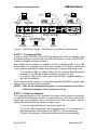
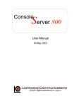
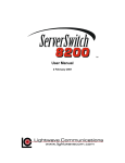
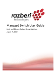
Product Manual
December 2001
Part Number 15.00.035
USB SERVERSWITCH
Lightwave Communications
Lightwave Communications, Inc.
100 Washington Street Milford, CT 06460 USA
(800) 871-9838 • (203) 878-9838 • Fax: (203) 874-0157
Email: [email protected] • Internet: www.lightwavecom.com
LCI Asia/Pacific
Postal address: P.O. Box 19 Glen Iris VIC 3146 Australia
Delivery address: 16 Network Drive Port Melbourne VIC 3207 Australia
+61 3 9646 1144 • Fax: +61 3 9645 3377
Email: [email protected] • Internet: www.lightwavecom.com.au
LCI Europe
Zaubzerstraße 11 Munich D-81677 Germany
+49-89-306-3810 • Fax: +49-89-306-3812
Email: [email protected] • Internet: www.lightwave.de
USB ServerSwitch Product Manual
Copyright © 2001 by Lightwave Communications. All rights reserved. No part of
this copyrighted material may be reproduced in any form or by any means without
prior written permission of Lightwave Communications, Inc.
Printed in U.S.A.
USB ServerSwitch is a Trademark of Lightwave Communications, Inc.
Lightwave Communications is a subsidiary of Lantronix Inc.
Part Number 15.00.035, Revision History:
Rev. A
Page 2 of 25
December 7, 2001
Initial Release
December 2001
Lightwave Communications
USB SERVERSWITCH
Table of Contents
1.0 USB ServerSwitch - Introduction ................................................................................. 4
USB ServerSwitch features:............................................................................................ 5
Specifications .................................................................................................................. 5
2.0 USB ServerSwitch - System Information...................................................................... 6
2.1 Video ........................................................................................................................ 6
DDC2B Support .......................................................................................................... 6
2.2 Keyboard / Mouse .................................................................................................... 6
2.3 System Control......................................................................................................... 7
3.0 On-Screen Menus ......................................................................................................... 8
Navigating the on-screen menus ................................................................................. 8
3.1 Main Menu ............................................................................................................... 8
Main Menu Options .................................................................................................... 9
System Setup Options ................................................................................................. 9
3.1.1 Main Menu: Auto Scan ................................................................................... 10
3.1.2 Main Menu: Jump to Port... ............................................................................ 11
3.2 System Setup .......................................................................................................... 12
3.2.1 System Setup: Port Setup ................................................................................ 13
3.2.2 System Setup: Menu Window Setup............................................................... 14
3.2.3 System Setup: Server Window Setup.............................................................. 15
3.3 Front-panel LCD Display....................................................................................... 15
Front Panel Controls.................................................................................................. 16
3.4 Error Messages....................................................................................................... 16
4.0 Operational Safety...................................................................................................... 17
5.0 Installation ................................................................................................................. 18
STEP 1 -- Unpacking the Items................................................................................. 18
USB ServerSwitch Rear Panel Connections ................................................................. 19
STEP 2 -- Initial Start-Up.......................................................................................... 19
STEP 3 -- Connecting CPUs ..................................................................................... 20
STEP 4 -- Power Up Sequence ................................................................................. 20
6.0 Cascading the USB ServerSwitch .............................................................................. 21
STEP 1 - Connect CONTROL Cable........................................................................ 22
STEP 2 - Connect Video Cascade Cables ................................................................. 22
STEP 3 - Turn the Auxiliary Unit On ....................................................................... 22
7.0
System Maintenance Features............................................................................... 23
7.1
Setting Factory Defaults.................................................................................... 23
7.2
Flash Update Procedure .................................................................................... 23
Materials:................................................................................................................... 24
Flash Update Steps:................................................................................................... 24
www.lightwavecom.com
Page 3 of 25
Lightwave Communications
USB SERVERSWITCH
1.0 USB ServerSwitch - Introduction
The USB ServerSwitch is an intelligent KVM switch for keyboard, high-resolution
video and mouse for a 2-User by 8-server configuration. The USB ServerSwitch
(for simplicity, it may be referred to as the “USBSS”) supports individual USB
keyboards and mice. The USB ServerSwitch has full-time keyboard and mouse
emulation to each PC or server. This assures that there will be no interruptions or
interference to boot processes or other CPU activity. The video switching circuitry
is designed with state of the art video multiplexers that support high-resolution
graphics adapters with video resolutions of 1600 x 1200 pixels.
Figure 1: USB ServerSwitch - Front Panel
The USB ServerSwitch front panel has a built-in 24 character, 2 line backlit LCD
display. The top line displays Port data for the currently-selected server port, and
the bottom line is dedicated to real-time status monitoring. The USB ServerSwitch
can be controlled either through on-screen menus (see section 3.0) or directly
using the Up and Down buttons on the USBSS (see Section 3.3).
The USB ServerSwitch’s rear panel provides USB connections for Keyboard and
Mouse and HD15 Video for 8 Servers (Inputs), 2 USER/OUTPUT console
positions, and CONTROL and Video Cascade ports for expanded configurations
(see Section 6.0) that supports up to 64 connected servers. Also found on the back
panel is the AC power input, fuse, and Power Switch for the unit.
Figure 2: USB ServerSwitch - Rear Panel
The USB ServerSwitch is designed for rack mounting in a conventional 19-inch
equipment rack, requiring 1RU (1.75 inches) of rack height. The unit may also be
placed on a shelf; and the included rack mounting flanges are removable. The unit
is convection cooled and does not require a fan or air conditioning.
Page 4 of 25
December 2001
Lightwave Communications
USB SERVERSWITCH
USB ServerSwitch features:
•
•
•
•
•
•
•
•
•
•
•
•
•
•
•
Rack mountable chassis, 1RU, rack mounting flanges included with unit
8 server ports per chassis, expandable to 64 ports by cascading units
Supports two Consoles with full Keyboard/Video/Mouse interfaces
Standard Input and Output connections
o 4 pin USB-B keyboard and mouse connectors from Servers
o 4-pin USB-A connectors for Keyboard and Mice for Users
o Video: HD15 female video connectors
o DB9 Control connections (intra-unit)
Cascade Control In: DB9 female
Cascade Control Out: DB9 male
Video Support for RGB, RGBS, RGBHV, up to 1600 x 1200 pixels
DDC2B video record support
Impedance-balanced RGB lines, 75 ohms
USB power sensing from server
On-screen menus
Backlit front-panel LCD display
Non-volatile memory for server names & options
Video cascade port for cascading USB ServerSwitch units
Distance between cascaded USBSS's may be up to 50 feet
Distance from CPU to USBSS = 25 feet
Distance from USBSS to User Consoles = 25 feet
Specifications
Dimensions:
• Rack size:
19"
• Height:
1 RU, 1.75" (4.45cm)
• Width:
17.5" (44.45 cm)
• Depth:
11.75" (29.85cm)
Weight: 10.4 lbs (4.70 kg)
Shipping Weight: 15 lbs (6.8kg)
Operating Environment:
• 0°C (32°F) to 50°C (122°F)
• 10-90% humidity, non-condensing
Power Requirements:
• Input Power: 90-253 VAC, 47-63 Hz, fused at 4 amperes
• Equipped with IEC-type power connector and location-specific cordset
• Power consumption: 12 watts
www.lightwavecom.com
Page 5 of 25
Lightwave Communications
USB SERVERSWITCH
2.0 USB ServerSwitch - System Information
2.1 Video
The USB ServerSwitch incorporates an active, high-bandwidth switch for graphics
adapter cards supporting resolutions up to 1600 x 1200 pixels. The system
supports DDC2B video records, and maintains a local copy of the video record for
each attached server (after a proper power-up sequence). A constant impedance
of 75 ohms is maintained on all video lines in the USBSS, so that the video signal
is not compromised by mismatched impedance. Monitor sense lines are also
transported by the USB ServerSwitch. The ID lines are buffered and passed from
the monitor to the attached graphics adapters in the servers.
Note: The USB ServerSwitch's USB interface is for discrete USB mice and
keyboards only, and will not support Monitors with USB-provided video controls.
DDC2B Support
The DDC2B video record is generated during the power-up of the system, and is
generated by each server that supports or requires the video record, or else
defaults to a generic VGA mode. The USBSS stores a copy of the DDC2B record
at each Server port, and when that server is switched to the User, that video record
information will be sent to the monitor for a proper video signal.
The video record is determined upon power-up of the system by checking the
video signal with the monitor connected to the User A port, and then the User B
port. If monitors are changed at a later date, it may be necessary to shut down the
USB ServerSwitch and/or the servers to regenerate the proper DDC2B record.
If using DDC2B, it is recommended that both User A and User B have similar video
monitors at their stations, since the DDC2B only supports one video record per
server.
2.2 Keyboard / Mouse
The USB ServerSwitch is an intelligent USB switch for the keyboard and mouse.
Each port emulates the keyboard and mouse fully, allowing an attached server or
PC to boot without having been previously selected. Power for each connected
device is monitored from the USB port.
Note: The USB ServerSwitch's keyboard and mouse interface is for discrete USB
mice and keyboards. It does not support graphics tablets, scanners, modems,
drives, hubs or other composite USB devices. Each USB-A receptacle on the
USBSS will support one USB mouse or USB keyboard.
If there is no connection on a USB server port, a status message "Inactive port" will
be displayed on the front panel display. The other attached servers are not
affected because of the keyboard and mouse emulation.
Each port maintains a local copy of the keyboard and mouse configuration. USB
Port numeration is maintained even when the user has de-selected a port. When
Page 6 of 25
December 2001
Lightwave Communications
USB SERVERSWITCH
the user switches from one port to another, the keyboard is set up just as it was
prior to switching to another port. The mouse behaves in a similar manner.
2.3 System Control
The USB ServerSwitch is controlled either by using the UP and DOWN arrows on
the front panel of the unit or via On-Screen Menus from their Console (Keyboard,
Monitor and Mouse).
The USBSS is a transparent device to the User. The User (of which there may be
one or two) can select which server they wish to access from their Console, from
up to 8 connected Servers. In cases where two or more USBSS units have been
cascaded, additional Servers can be accessed by the two Users, up to a maximum
of 64 Servers (8 units cascaded in all).
To access the USBSS’s switching capability, the User must “wake up” the onscreen display to control the system by pressing both ‘Cntl’ keys simultaneously
(referred to as ‘Cntl-Cntl’), or press the Scroll Lock key twice (within one second)
on their keyboard.
If the system administrator is near the USBSS (for example, in a backroom
location), the sysadmin may instead select a server by using the Up and Down
buttons on the front of the unit. The display will scan through which Servers are
available, if auto-scan is active. Server selection can also be accomplished
manually by pressing the Up arrow or Down arrow buttons. To select between
User A and User B, press both Up and Down buttons on the front panel of the
USBSS at the same time to shift between the two users.
www.lightwavecom.com
Page 7 of 25
Lightwave Communications
USB SERVERSWITCH
3.0 On-Screen Menus
On-screen Menus are used for two purposes:
• Server Port selection for a Console
• System setup programming for the USB ServerSwitch
On-Screen Menus are displayed on the User's monitor. Either Console may
administer the system, but only one user may edit the setup at a time.
NOTE:
While in the on-screen menu mode, the "Caps Lock", "Num Lock", and
"Scroll Lock" LEDs will flash on the User Console’s keyboard.
Navigating the on-screen menus
•
•
•
•
•
•
Press both Control keys (Cntl-Cntl) to access the on-screen menus, or
press the Scroll Lock key twice (within one second)
Up Arrow/Down Arrow
+ and - keys on number pad
Enter (select or scroll through options)
Esc to exit, or to back up one level
Most options have a single-character hot-select key, highlighted and
capitalized on the screen. Press that letter to select that option.
3.1 Main Menu
Pressing and releasing both CONTROL buttons (Ctrl-Ctrl) on either Console's
keyboard will bring up the main menu of the USB ServerSwitch.
Lightwave Communications Inc.
Curr: File Server 1
USBss System Setup
no Auto scan
Jump to port...
Disabled
File Server 1
1
File Server 2
2
Print Server
3
Email Server
4
Engineering
5
Enterprise
6
Firewall
7
Fax Server
8
Next unit Esc exits
Note: This window will show the current server port (e.g., Curr: File Server 1).
Window color settings may be different than above.
Page 8 of 25
December 2001
Lightwave Communications
USB SERVERSWITCH
Main Menu Options
Navigate through the Main Screen window by using the up and down arrows on
your keyboard and “Enter” to select from the following:
• System Setup - for customizing your USB ServerSwitch.
• Auto Scan - This option scans each attached port for a duration
determined by the user. See Section 3.1.1.
• Jump to port... - You can jump to specific ports several different ways.
By selecting “Jump to port...”, navigate by typing either the name or
number of the desired port. Press [J] and press Enter to get a prompt to
enter the server Port name or number. See Section 3.1.2.
• Disabled - Select this entry to disconnect this User Console (A or B) from
all Server ports (enabling the other user to access all Server ports).
• Ports 1 through 8 - direct-select an association with Server Ports 1
through 8
• Next unit - go to the Next page of eight server ports using [N] (used in
cascaded applications to access higher-numbered servers)
• Prev unit - go to the Previous page of eight server ports using [P]
• Esc exits - press [Esc] to exit the server window. If Scanning is enabled,
port scanning will start upon exiting the Main Menu.
NOTE: You can set up your USB ServerSwitch options, port names, etc.
before you connect your servers.
The preset values do not list any server names, but instead identify each port with
a generic Port number. The Port Number is fixed and always displayed in the onscreen display, even if the user enters a name.
System Setup Options
System Setup Options are used for system maintenance and software updates.
The System Setup options are also accessible from the Main Menu Screen, by
pressing the F1 key to access the System Setup screen. System Options include
System Flash Memory Update (F) and Load Factory Settings (F12).
Caution: Do NOT use System Setup Options during normal operation, as these
will erase all user-entered data and may require a system reset. Updating the
FLASH memory requires that the System re-enumerate (reboot) which can
interrupt normal operation.
Refer to Section 7 for System Maintenance features and instructions.
www.lightwavecom.com
Page 9 of 25
Lightwave Communications
USB SERVERSWITCH
3.1.1 Main Menu: Auto Scan
During auto scan the USB ServerSwitch will scan through each server, stopping at
each active port for the duration assigned in the System Setup menu. The port
name and number will appear as the attached servers are scrolled through.
Exiting the menus using the Escape key will either send the user into auto scan
mode or to a single server, depending on which option is selected.
• To exit the auto scan mode, press any key on your keyboard.
• Return to the main menu by pressing “Ctrl-Ctrl”, or Scroll Lock twice.
• To exit the on-screen menus, press 'Esc' until no more screens are
shown.
Use the + and - keys on the number pad of your keyboard, or [A] key, for 'start
Auto scan' or 'no Auto scan'. Also see Section 3.2.1 for Server Port Setup for Auto
Scan.
NOTE:
Server Ports can be individually programmed to be Scanned or Not
Scanned. Only SERVERs that are set to be scanned, and are
connected and powered on will be scanned.
Lightwave Communications Inc.
Curr: File Server 1
USBss System Setup
no Auto scan
Jump to port...
Disabled
File Server 1
1
File Server 2
2
Print Server
3
Email Server
4
Engineering
5
Enterprise
6
Firewall
7
Fax Server
8
Next unit Esc exits
Page 10 of 25
December 2001
Lightwave Communications
USB SERVERSWITCH
3.1.2 Main Menu: Jump to Port...
Jump to Port - Jump directly to any port from the Main Menu by entering either
the port name or port number. Select Jump to port and press Enter.
Lightwave Communications Inc.
Curr: File Server 1
USBss System Setup
no Auto scan
Jump to port...
Disabled
File Server 1
1
File Server 2
2
Print Server
3
Email Server
4
Engineering
5
Enterprise
6
Firewall
7
Fax Server
8
Next unit Esc exits
The screen will change to the following 'Enter port' prompt:
no Auto scan
Enter port:
Disabled
Enter the port name or port number, and press Enter. You will be immediately
switched to that port (if available) and exit the on-screen mode.
NOTE:
When entering the port name, make sure you enter the name as
case sensitive if “Case sensitive names” is selected in the System
Setup menu. If you would like to enter names ignoring case, select
“Ignore Case in Names” in the System Setup menu.
www.lightwavecom.com
Page 11 of 25
Lightwave Communications
USB SERVERSWITCH
3.2 System Setup
Selecting the 'USBSS System Setup' line and pressing Enter will go into Set Up:
USBss System Setup
Version: 1.34
Auto scan duration:
10 sec
Error Message duration: 5 sec
ignore Case in names
Server Name is Temporary
Port setup...
menu Window setup...
Server window setup...
Selecting “Port setup,” “menu Window setup,” or “Server window setup” will open
one of three sub-menus to be discussed in the following pages.
The options at the main System Setup window can be selected by highlighting the
desired option using the up/down arrows on your keyboard to select the option
and scrolling through the values of each using either the +/- keys OR the “Enter”
key to select your desired value.
• Auto Scan Duration - Select the length of time, between 2 to 30 seconds,
that each port will be scanned during auto scan.
• Error Message Duration - Select the amount of time (2 to 15 seconds)
each error message appears on the LCD as the system scans the ports.
• Ignore Case in Names/Case Sensitive Names - This option lets you
dictate whether the names entered in the “Jump to port...” mode need to
be case sensitive, or not.
• Server Name is Never On/Always On/Temporary - As you scroll
through each port and/or as each port goes through auto scan, you have
the option of having the Server Window with the connected port's
name/number appear permanently, temporarily, or not at all.
• Port Setup - discussed in a Section 3.3
• Menu Window Setup - discussed in a Section 3.2.2
• Server Window Setup - discussed in a Section 3.2.3
NOTE: System Setup options and values are automatically saved to the
memory of the USB ServerSwitch.
Page 12 of 25
December 2001
Lightwave Communications
USB SERVERSWITCH
3.2.1 System Setup: Port Setup
Edit Port Names - Select the desired port using the up and down arrows and the
“Enter” key. Press 'Esc' to return to the previous menu screen.
Port Setup
Edit Port Names
+Port
1
+Port
2 Default is blank
+Port
3 Enter a Port
+Port
4 Name here;
+Port
5 alpha-numerics
+Port
6 and
-Port
7 + - / . ; are OK
+Port
8
15 characters
F8 toggles Inactive msg
+/keypad + or - toggles autoscan
Enter to edit a port name
; Port Autoscan Enabled
Prev unit
Down
Enter any name, up to 15 characters long. Note that case-sensitivity of port names
may be enabled or disabled system-wide, if required. Valid characters include
A through Z, a through z, digits 1 through 9 and 0, and + (plus), - (minus),
/ (slash), . (period) and : (colon).
• The symbol on-screen represents Auto Scan Enabled for this port. A
Port with the symbol showing will be included in a scan of active ports.
Select which ports should be scanned during auto scan mode (default is all
ports). Toggle auto scan on/off for each port using the + or - keys.
• The + and - symbol before the Port number shows the LCD Inactive
message status (+ indicates that the front panel LCD will display a status
message for this port, - indicates that the front panel status message is
disabled for this port). To change this setting, select the Port and press F8
to turn the status message option On or Off.
Note:
Refer to Section 3.1.1 for Auto-Scan system setup options.
www.lightwavecom.com
Page 13 of 25
USB SERVERSWITCH
Lightwave Communications
3.2.2 System Setup: Menu Window Setup
The Menu Setup window allows the user to change the Position and the Colors
displayed on the Menu Window. Customize the location and color of the Main
Menu window by selecting any of the options and pressing “Enter”.
Menu Window Setup
move
move
move
Move
Up
Down
Left
Right
Background color
Foreground color
Highlight color
Select menu color
Esc exits
The on-screen position of the Menu Window may
be moved (U)p, (D)own, (L)eft, or (R)ight.
You may also select the Line (e.g., move Up) and
press Enter to move the display or change the
color option as desired.
Lightwave Communications
Curr: File Server 1
USBSS System Setup
no Auto scan
Jump to port...
Disabled
File Server 1
1
File Server 2
2
Print Server
3
Email Server
4
Engineering
5
Enterprise
6
Firewall
7
Fax Server
8
N t
it E
Inc.
it
The color choices include 8 color options for each
of (B)ackground Color, (F)oreground Color
(normal
screen
text),
(H)ighlight
Color
(background of a highlighted line or block of text)
and (S)elect Menu Color (highlight color for Menu
hot-select keys). You should assign a different
color for each of these options.
Figure 3 Terminal showing Menu Window
Page 14 of 25
December 2001
USB SERVERSWITCH
Lightwave Communications
3.2.3 System Setup: Server Window Setup
The Server Window contains the port name and number that the User is connected
to. The Server window is displayed briefly when connecting to a server.
File Server 2
8
Figure 4 Terminal showing sample Server Window display
Select the color and position of the Server Window by scrolling through the above
options using the up/down arrow keys and pressing “Enter” to move the window
and/or change colors. Use the color and position options listed in Section 3.2.2.
To select a specific function, press the hot-key letter that is capitalized /
highlighted.
3.3 Front-panel LCD Display
The USB ServerSwitch is equipped with a backlit LCD display. The display is used
in conjunction with the front panel UP and DOWN arrow buttons when selecting
Servers for either user. A 'normal' display is shown below.
A: Port 1 Name
When the USB ServerSwitch is turned on the LCD will show the version of the
switch, and perform internal system diagnostics. Within a minute of power-up, the
display shows which Server Port is connected to which Console (A or B) on the top
line, and also shows real-time error messages using the bottom line.
www.lightwavecom.com
Page 15 of 25
Lightwave Communications
USB SERVERSWITCH
The display is 2 lines by 24 characters in each line. Note that the display will only
show Console A or Console B information at any time (not both Consoles at the
same time).
B: Port 13 name here
Inactive Port
The Port Name information entered from the System Setup screens (using the onscreen System Setup commands) will be displayed. You can change the active
port on the USB ServerSwitch either via the on-screen menu or by using the up
and down buttons on the unit.
If multiple USBSS units are cascaded, the same display information is repeated on
all front panel displays, and is selectable from the Master USBSS unit.
Front Panel Controls
The front panel display shows which Console is connected to which Server; or, if
'disabled' appears, that Console is not connected to any servers at that time.
• Press and release the Up arrow button to select the next Server number.
If you reach the highest port number, the next value is 'disabled', and then
it restarts at Port 1.
• Press and release the Down arrow button to select the previous server
number. If you reach the lowest number, the next value is 'disabled'
followed by the highest port number.
• To switch between Console A and Console B, press and release both the
UP and DOWN buttons on the front panel at the same time. This option is
blocked while another user is accessing the System using the On-Screen
Menus.
• Front panel controls are disabled on Auxiliary USBSS units; only the
Master USBSS unit's front panel buttons will operate.
To switch between Console A and Console B, press both the UP and DOWN
buttons on the front panel at the same time. This option is blocked while another
user is accessing the System using the On-Screen Menus.
3.4 Status Messages
The bottom line of the front panel display will show a status message if an unusual
condition exists. The most common display message will be that of a Server's USB
cord becoming disconnected.
Page 16 of 25
December 2001
Lightwave Communications
USB SERVERSWITCH
4.0 Operational Safety
The USB ServerSwitch should be installed in a suitable equipment room
environment. It is designed for rack mounting in a 19-inch equipment rack.
A) The USB ServerSwitch is designed to operate in an ambient temperature of
0°C (32°F) to 50°C (122°F), 10-90% humidity, non-condensing. Ensure that closed
or multi-unit racks maintain an ambient temperature not to exceed 50 °C (122 °F).
B) The USB ServerSwitch is designed to operate with convection cooling provided
by the air holes located in both sides of the unit. Make sure that these ventilation
holes are not obstructed by equipment placed directly in contact with either side of
a USB ServerSwitch.
If the unit is placed on a shelf, be sure to allow air space around the unit for air
flow, especially to the sides of the unit. The unit is shipped with four rubber feet
which will raise the unit off of a counter or shelf and allow air flow beneath the unit.
C) Make sure that each USB ServerSwitch unit is properly supported in the front
of the unit, by bolting the USB ServerSwitch into a standard 19 inch rack.
D) The USB ServerSwitch has a universal AC power supply which requires
90-253 VAC, 47-63 Hz at 0.5 ampere (protective fuse is 4 amperes). Power
consumption is 12 watts. It is important for each unit to be supplied with the proper
operating voltage and current.
E) All rack mounted equipment should be reliably connected to earth ground. Pay
close attention to grounding at all times, particularly when equipment is not directly
connected to power mains (such as when a power strip is used).
WARNING: The top cover should not be removed due to the potentially
hazardous voltages in the unit. No user serviceable parts are
inside the USB ServerSwitch. All repairs should be performed
by Lightwave to avoid cancellation of the warranty.
Note: This equipment has been tested and found to comply with the limits for a Class A
digital device, pursuant to Part 15 of FCC Rules. These limits are designed to provide a
reasonable protection against harmful interference when the equipment is operated in
a commercial environment. This equipment generates, uses and can radiate radio
frequency energy and, if not installed and used in accordance with the instruction
manual, may cause harmful interference to radio communications. Operation of this
equipment in a residential area is likely to cause harmful interference in which case
the user will be required to correct the interference at his own expense.
www.lightwavecom.com
Page 17 of 25
Lightwave Communications
USB SERVERSWITCH
5.0 Installation
The USB ServerSwitch unit is designed to occupy 1 RU (1.75 inches) of rack
space. Sufficient space is required behind the rear panel of the unit to allow for
attached cables bend radius (6 inches should be sufficient). It is helpful to plan
ahead if additional units might be added to the configuration at some later date. If
cascading (adding USB ServerSwitches) is to be used, make certain to leave
enough space in the rack for additional units. The USB ServerSwitch installation
can be expanded at any time, without interfering with servers connected to existing
switches.
Figure 5: USB ServerSwitch – Front and Rear panels
STEP 1 -- Unpacking the Items
Verify that the following items are located in the packaging.
• (1) USB ServerSwitch
• (1) AC Power Cordset
• (1) Cable - DB9 Female to Male Serial data cable (6 foot long)
• (1) USB ServerSwitch Product Handbook
• Cables, as required for your number of servers and units
NOTE! Optional cable kits are available. (1) Kit contains:
• (1) USB-A to USB-B cable, to connect a server's keyboard and mouse to
the USB ServerSwitch
• (1) HD15 male-male video cable to connect server video adapter to the
USB ServerSwitch
• Cascade kit includes two HD15 male-male cables. The DB9 male-tofemale cable required is shipped with the USB ServerSwitch
NOTE! Other items may be ordered or shipped separately.
Page 18 of 25
December 2001
USB SERVERSWITCH
Lightwave Communications
USB ServerSwitch Rear Panel Connections
2
1
3
4
5
10
6
11
7
12
8
13
9
14
15
Figure 6: USB ServerSwitch - Rear Panel View, Connections
Figure 6 Legend:
1)
HD15 Video for Server #1
2)
USB-B input receptacle for Server #1
3)
HD15 Video for Server #2
4)
USB-B input receptacle for Server #2
5)
HD15 Video CASCADE IN for User Console A (not used on Master)
6)
USB-A receptacle #1 for Mouse or Keyboard for User A
7)
USB-A receptacle #2 for Mouse or Keyboard for User A
8)
HD15 Video Out for User A, or Cascade Out
9)
Control Out: DB9M; sends signal for box to box communications
10)
HD15 Video CASCADE IN for User Console B (not used on Master)
11)
USB- A receptacle #1 for Mouse or Keyboard for User B
12)
USB- A receptacle #2 for Mouse or Keyboard for User B
13)
HD15 Video Out for User B, or Cascade Out
14)
Control In: DB9F; receives signal for box to box communications
15)
AC power input (IEC, universal AC power), power switch and fuse
STEP 2 -- Initial Start-Up
a) Connect the AC Power Cord to the USB ServerSwitch and plug the power cord
into a grounded outlet.
b) Connect a monitor, keyboard and mouse (optional) to the USER connections
(A or B) on the rear of the USB ServerSwitch. The mouse and keyboard for each
user can be connected to either USB-A connector, only one device per connector.
c) Turn the USB ServerSwitch on. It takes approximately one minute to boot up.
Note:
At this point, it is possible to program the unit, if so desired.
Follow the steps as listed in Section 3 of this manual to access the
on-screen menus.
www.lightwavecom.com
Page 19 of 25
USB SERVERSWITCH
Lightwave Communications
A
SERVERS
1
3
USB
5
USER A
USB
US
B
C
2
4
USB
6
USB
Caution! Replace with same type and rating fuse.
7
USB
USB
entela
®
CONTROL OUT
Certified
8
USB
USB
CASCADE IN
USER B
CONTROL IN
100-240V ~, 0.5A, 50/60 Hz
T 4A, 250 VAC
Figure 7 -- USB Server Switch -- Rear Panel Connections, 4 Servers shown
STEP 3 -- Connecting CPUs
Connect a single SERVER to the USB ServerSwitch and verify its operation. Use
the cables that were provided with the USB ServerSwitch to attach the SERVER.
Connect the cables as shown in Figure 7.
Make certain that all servers are powered off when connecting them to the USB
ServerSwitch. It is important to note that some servers do not allow for keyboards
to be connected and disconnected during operation. This may cause them to halt.
1) A standard USB-A to USB-B cable from the Server's Mouse/Keyboard
connector to the USB ServerSwitch. Maximum length is 25 feet.
2) An HD15 male-to-male video cable from the Server graphics adapter to
the USB ServerSwitch.
Once this is complete, continue to connect the remaining SERVERs. Repeat these
steps until all of the devices are connected.
NOTE! CPUs can be connected to any port. It is not necessary to use Port 1
as the first connection, Port 2 as the second, etc.
STEP 4 -- Power Up Sequence
The power-up sequence is very important for proper monitor operation, especially
if using DDC2B-compatible monitors. In some cases (e.g., SGI Onyx 3xxx series,
others) you must completely reboot your server to start the video signals. After all
cables are connected and the system is ready for use:
(1) Turn the Video Monitors for User A and User B On.
(2) Turn the USB ServerSwitch unit On (power switch to 'I') if not already on.
Wait approximately one minute for the USBSS to start up completely.
(3) Start Up the Servers. USB enumeration should occur automatically
Page 20 of 25
December 2001
USB SERVERSWITCH
Lightwave Communications
6.0 Cascading the USB ServerSwitch
This section only applies to configurations with more than one USB ServerSwitch.
Up to eight (8) USB ServerSwitch units may be cascaded for a maximum of 64
server ports and 2 Console Ports. See Figure 8.
A
SERVERS
3
1
USB
5
USB
USB
USER A
US
USB
B
C
2
4
USB
6
USB
USB
USB
USB
USER B
A
5
4
USB
6
USB
USER A
US
USB
USB
USB
B
USB
4
USB
Caution! Replace with same type and rating fuse.
®
CONTROL OUT
USER B
CONTROL IN
USER A
100-240V ~, 0.5A, 50/60 Hz
T 4A, 250 VAC
Caution! Replace with same type and rating fuse.
7
USB
6
USB
entela
CASCADE IN
USB
US
B
C
2
T 4A, 250 VAC
Certified
A
5
USB
100-240V ~, 0.5A, 50/60 Hz
8
SERVERS
3
1
CONTROL IN
7
USB
USB
®
CONTROL OUT
Certified
CASCADE IN
C
2
entela
8
SERVERS
3
1
Caution! Replace with same type and rating fuse.
7
entela
®
CONTROL OUT
Certified
8
USB
USB
CASCADE IN
USER B
CONTROL IN
100-240V ~, 0.5A, 50/60 Hz
T 4A, 250 VAC
Figure 8: Cascading USB ServerSwitch systems (3 USB-SS's shown)
www.lightwavecom.com
Page 21 of 25
Lightwave Communications
USB SERVERSWITCH
If more than eight servers are to be connected, then cascading of the USB
ServerSwitch is necessary. In a cascade environment, the first unit that is installed
is considered the "Master Unit". All information is stored in the Master Unit.
Cascading the units is very simple.
If the existing USB ServerSwitch unit has been installed and running, it is not
necessary to turn off the power to the Unit. The installation of additional units can
be accomplished without any interruption to the existing servers.
STEP 1 - Connect CONTROL Cable
Connect the DB9 Serial data cable (supplied with each USB ServerSwitch) from
the Master Unit "Control Out" port to the first Aux Unit "Control In" port. Make
certain that these cables are securely fastened to the units. These data cables
carry all mouse, keyboard, and control data necessary for cascading units.
If more units are cascaded, connect the Control Out port to the Control In port of
the next unit to be cascaded, using a DB9 Female to Male serial cable.
STEP 2 - Connect Video Cascade Cables
Connect the "Video Cascade In" ports on the Master Unit to the USER video ports
(Port A Output to Port A Cascade In, Port B Output to Port B Cascade In). This will
allow the video signals from the Aux units to reach the Consoles that are
connected to the Master unit. Follow this procedure for as many Aux units (one
Master plus 7 Auxiliary units, max) as required for the servers.
STEP 3 - Turn the Auxiliary Unit On
Turn on all of the Auxiliary units that were installed. Connect the servers to these
units as done in the earlier installation for a single unit.
To install a USB ServerSwitch as the new master, turn the old master off, connect
it, and then turn it back on. Turning off the old master may affect servers
connected to it, so it is recommended that you shut down any SERVERs
connected to the old master before performing this installation.
Page 22 of 25
December 2001
Lightwave Communications
USB SERVERSWITCH
7.0 System Maintenance Features
System Maintenance features include Flash Memory Update and Restore Factory
Settings. These options require the system be taken out of service for
maintenance.
The System Setup options are also accessible from the Main Menu Screen, by
pressing the F1 key to access the System Setup submenu. System Options
include System Flash Memory Update (F) and Load Factory Settings (F12).
Other options listed there are for FUTURE USE and should not be attempted.
Caution: Do NOT use System Setup Options during normal operation, as these
can erase all user-entered data and will require a system power reset to restore
normal operation.
7.1
Setting Factory Defaults
If it becomes necessary to reset the USB ServerSwitch to its factory-set values, the
users may do so from the System Setup menu. The System must be out of
service during this procedure. All connections will be dropped, and all default
values will be restored. The whole process takes less than 5 minutes.
1. Access the System Setup menu by pressing Cntl-Cntl on any attached
keyboard, or pressing the Scroll Lock key twice.
2. Once at the System Setup menu, access the System Setup submenu by
pressing the <F1> key.
3. Press the <F12> key. You are prompted "Are You Sure?", and then press
the Y key to confirm that the USB ServerSwitch parameters and server port
names should be set to the factory default values. If not, press 'N' to exit this
option.
4. The Display will change to 'Restoring Factory Defaults'. Then, the on-screen
menu will temporarily disappear, and reappear at the main on-screen menu
once the parameters are reset. The front LCD display will show "Save
Database" when it is completing the update.
The ServerSwitch will not be able to switch to another port or pass
keyboard/mouse signals during the reset to factory defaults.
7.2
Flash Update Procedure
The flash update feature allows the user to install newer versions of operating
software in the USB ServerSwitch without removing the unit from its installation
(the system must be removed from service, however). New software revisions will
be released from time to time to add features to the USB ServerSwitch or make
changes for customer requests. Note that the users will not be able to switch
server ports during the update. The whole process takes less than 10 minutes.
The binary file for the flash update can be downloaded from
ftp://ftp.lightwavecom.com/pub/products/USB_SS/software/
www.lightwavecom.com
Page 23 of 25
Lightwave Communications
USB SERVERSWITCH
Materials:
1. Laptop or other computer with RS-232 serial I/O port
2. Serial cable with DB9 male end and mating connector for the above
computer's serial port
3. Communications software capable of XMODEM uploads
4. USB ServerSwitch software update file
Flash Update Steps:
1. Download the FLASH file for the USBSS from the Lightwave FTP site
to your Laptop or computer.
2. Connect the computer's serial port to the CONTROL IN port of the
USB ServerSwitch. [If the unit had been cascaded with other units,
the cascade connections must be broken. Each USBSS unit must be
updated individually.]
3. Start the communications software. Configure the communications
parameters to 38,400 baud, 8 data bits, no parity, 1 stop bit, and DTE
(38.4K 8N1 DTE). Select the correct serial port (i.e., COM1) as the
I/O port if not already selected.
4. Access the USBSS's System Setup menu by pressing Cntl-Cntl on
any attached keyboard, or pressing the Scroll Lock key twice.
5. From the System Setup menu, press the <F1> key to access the
defaults/flash update menu. Press the F key to start the FLASH
update mode of the USB ServerSwitch. To interrupt the FLASH
update mode, turn the USBSS power off and back on.
USB ServerSwitch Boot v1.00
Copyright 2001 by Lightwave Communications Inc.
Start XMODEM transfer of USB ServerSwitch flash memory
cccccc
6. Begin uploading the flash update binary file from the computer
attached to the CONTROL IN port to the USB ServerSwitch. Once
the F key has been pressed, the USB ServerSwitch sends a
message through the serial port prompting the Terminal program to
send the binary update file.
7. The user selects the Flash file on the computer. It is assumed that
the file transfer begins, although there is no visible confirmation
through the user's computer screen that the flash update has begun.
After about two minutes, the file upload (from PC to USBSS) is
completed. If no response after 5 minutes, you must start over.
Page 24 of 25
December 2001
Lightwave Communications
USB SERVERSWITCH
8. When the USB ServerSwitch has received the entire file, it will
prompt the user through the serial port to confirm that the file is
correct. Check the file version to be certain that it is the version that
you wish to upload to the USB ServerSwitch system.
9. When ready to modify the flash, select 'y' for 'continue with
programming'. NOTE: DO NOT TURN THE POWER OFF at this
point.
Start XMODEM transfer of USB ServerSwitch flash memory
cccccccccc
Received: USB ServerSwitch v2.04
Continue with programming? (y/n) y
10. The flash memory will be erased, and the new flash file will then be
saved.
11. You will get a prompt stating "Flash Programming Complete" after
less than a minute. Finally, it will state "Starting System".
12. After you see the Starting System prompt, the Flash update is
completed, and the USBSS is ready to go. Simply disconnect your
PC from the CONTROL IN port, and return all connections to normal.
Erasing the flash (takes about 10 sec.)
Programming FLASH ...........................................................
Flash programming complete.
Starting System.
13. To verify that the System Flash has been updated, go to the Main
Menu, select the System Setup screen and see the version number
as listed on the screen.
14. You may also verify the System Flash version by pressing and
holding both front panel buttons for more than 3 seconds. The front
panel display will change to a diagnostic mode (during which time the
system in inoperative) and list the system firmware version. You
MUST exit this diagnostic mode by pressing both front panel buttons
for more than 3 seconds again, in order to return the unit to service.
www.lightwavecom.com
Page 25 of 25