1
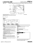
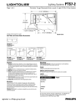
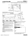
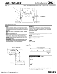
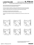
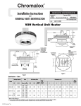
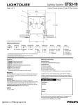
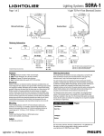
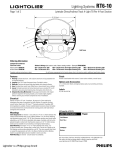
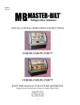
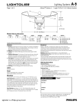
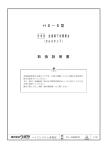
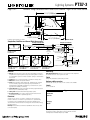
Lighting Systems
1BHFPG
PTS7-3
1FSJNFUFS5SPVHI3FDFTTFE%JSFDU-PVWFSX"JS$IBOOFM-JHIU51FS'PPU4FDUJPO
11-1/4” (28.58cm)
5
7 -1/16”
(19.94cm)
2
3
1
6
4
8-1/4” (20.96cm)
7
1-5/16” (3.33cm)
Complete ordering instructions on back.
Quarter Scale
Sample Run, End Plate and Corner Block Accessories
Example of Straight Run
Example of Pattern Run
10' 2-1/4” (310.52cm)
21' 10-3/4” (677.39cm)
60"
84"
14" (35.56cm)
60"
End Cap Set
PTS7EP Standard
PTS7EPA Air
14” (35.56cm)
14" (35.56cm)
9' 0” (274.32cm)
84"
Lighted
Telescoping
Unit
1-1/2”
(3.81cm)
8 -1/2” (245.11cm)
90° Inside Corner
48"
4-3/4” (12.07cm)
8' 1/2”
(245.11cm)
Telescoping
Unit (3 places)
8' 1/2”
245.11cm
1-1/2” (3.81cm)
48"
90° Inside
PTS7C901 Standard
PTS7C901A Air
90° Outside
PTS7C900 Standard
PTS7C900A Air
135° Inside
PTS7C1351 Standard
PTS7C1351A Air
135° Outside
PTS7C1350 Standard
PTS7C1350A Air
90° Outside Corner
1-1/2” (3.81cm)
Features
Mountings
1. Housing: Die-formed steel, slotted for air return. Integral flanges at each end
strengthen the housing and permit housings to be bolted together in continuous
runs and facilitate suspension of fixture. Concealed openings for heat extraction
and air return.
2. Lamping: One T8 or T12 fluorescent lamp, as specified. Provided by others.
3. Reflector: Die-formed semi-specular aluminum.
4. Louver: Semi-specular anodized aluminum, 40° lengthwise by 30° minimum
crosswise shielding. Supported along both edges by concealed frame of
extruded aluminum. Bold baffle, prismatic lens, gold anodized louver, open or
egg crate louver available, consult factory.
5. Socket Channels: Die-formed, pre-painted steel held by support brackets and
allows for up to 6” (15.24cm) lamp overlap.
6. Ceiling Trim: Extruded aluminum with integral aligner splines.
7. Air Supply Channel: For air supply or ducted air return. Ducted air return
requires Anemostat #PRTS or equivelant (by others).
Wall Adjustment Bracket - Allows for inconsistencies in wall straightness.
Die-formed steel used to mount system to the wall.
Electrical
Specify 120 volt or 277 volt. 3 conductor, 18 gauge wire. Color-coded quick
connectors allow ease of connection for joiner modules. For special circuiting,
consult factory. Factory installed ballast disconnect allows the ballast to be
disconnected from and reconnected to incoming power under load without turning
the entire circuit off.
Dimming: Advance Mark X, use Advance compatible two-wire control (no extra
control lead required).
Finish
Ceiling trim painted baked enamel semi-gloss white.
Options and Accessories
90° inside, 90° outside, 135° inside, and 135° outside corerns available.
Labels
UL, cUL and I.B.E.W.
Job Information
Type:
Job Name:
Cat. No.:
Lamp(s):
Notes:
"JSQPSU3PBE'BMM3JWFS."t
t'BY
We reserve the right to change details of design, materials and finish.
XXXMJHIUPMJFSDPN½1IJMJQT(SPVQt #
PTS7-3
Lighting Systems
1BHFPG
1FSJNFUFS5SPVHI3FDFTTFE%JSFDU-PVWFSX"JS$IBOOFM-JHIU51FS'PPU4FDUJPO
Performance
90
deg
450
65˚
600
55˚
750
900
45˚
050
0˚
5˚
15˚
25˚
35˚
REPORT NO: LRL 499-5D
LAMPS: 1-FO32T8
EFFICIENCY: 46.7%
0
0
0
0
0
0
0
0
0
0
0
39
153
440
560
669
754
885
969
950
833
0
0
0
0
0
0
0
0
0
0
0
15
90
120
338
532
705
833
949
920
833
0
0
0
0
0
0
0
0
0
0
0
2
5
13
79
288
512
677
778
837
833
0
0
0
0
0
0
0
0
0
0
0
2
3
8
34
64
103
225
386
704
833
Ordering Information
0
0
0
0
0
0
0
0
0
0
0
2
3
9
14
32
55
104
285
620
833
ZONAL LUMEN SUMMARY
LUMENS
% BARELAMP
1354
46.7
0
0.0
1354
46.7
ZONE
0-90
90-180
0-180
10
52
45
39
34
30
27
24
21
19
17
15
% LUMINAIRE
100.0
0.0
100.0
Quick Calculators
ONE SIDE MOUNTING
NO OPPOSITE WALL
ONE LIGHT
Cat No.
PTS7T148A PTS7184A PTS7160A PTS7148A PTS7136A PTS7124A
Size
27" to 48"
84"
60"
48"
36"
24"
Lamps
1-4 Foot 2-4 Foot
2-3 Foot
1-4 Foot
1-3 Foot
1-2 Foot
Type
Tele
Module
Module
Module
Module
Module
4 '3"-6'0"
1
1
5'3"-7'0"
1
1
6'3"-8'0"
1
1
7'3"-9'0"
1
1
8'3"-10'0"
1
1
1
9'3"-11'0"
1
1
10'3"-12'0"
1
1
1
11'3"-13'0"
1
1
1
12'3"-14'0"
1
1
1
13'3"-15'0"
1
1
1
14'3"-16'0"
1
1
1
15'3"-17'0"
1
1
1
1
16'3"-18'0"
1
2
17'3"-19'0"
1
1
1
1
18'3"-20'0"
1
2
1
19'3"-21'0"
1
2
1
20'3"-22'0"
1
2
1
21'3"-23'0"
1
2
1
22'3"-24'0"
1
2
1
1
23'3"-25'0"
1
3
24'3"-26'0"
1
2
1
1
25'3"-27'0"
1
3
1
26'3"-28'0"
1
3
1
27'3"-29'0"
1
3
1
28'3"-30'0"
1
3
1
29'3"-31'0"
1
3
1
1
30'3"-32'0"
1
4
31'3"-33'0"
1
3
1
1
32'3"-34'0"
1
4
1
33'3"-35'0"
1
4
1
34'3"-36'0"
1
4
1
35'3"-37'0"
1
4
1
36'3"-38'0"
1
4
1
1
37'3"-39'0"
1
5
38'3"-40'0"
1
4
1
1
39'3"-41'0"
1
5
1
40'3"-42'0"
1
5
1
41'3"-43'0"
1
5
1
42'3"-44'0"
1
5
1
43'3"-45'0"
1
5
1
1
44'3"-46'0"
1
6
45'3"-47'0"
1
5
1
1
46'3"-48'0"
1
6
1
47'3"-49'0"
1
6
1
48'3"-50'0"
1
6
1
49'3"-51'0"
1
6
1
50'3"-52'0"
1
6
1
1
51'3"-53'0"
1
7
52'3"-54'0"
1
6
1
1
0
1
2
3
4
5
6
7
8
9
10
COEFFICIENTS OF UTILIZATION
% EFFECTIVE CEILING CAVITY REFLECTANCE
80
70
50
% WALL REFLECTANCE
50
30
10
50
30
10
50
30
56
56
56
54
54
54
52
52
50
49
47
49
48
46
47
46
45
43
41
44
42
40
43
41
41
38
35
40
37
35
39
36
37
34
31
36
33
31
35
33
33
30
27
33
30
27
32
29
30
27
24
30
27
24
29
26
28
24
21
27
24
21
27
24
25
21
19
25
21
19
24
21
23
19
17
22
19
17
22
19
21
17
15
21
17
15
20
17
1.5
2.5
3.5
4.5
5.5
6.5
7.5
8.5
9.5
63
33
22
18
16
15
14
12
12
76
51
33
23
18
DISTANCE FROM CEILING, FT
75˚
300
180
15
51
45
35
28
23
19
40
38
33
27
23
20
ONE SIDE MOUNTING
6 FT BETWEEN WALLS
1.5
2.5
3.5
4.5
5.5
6.5
7.5
8.5
9.5
0
2
4
6
8 10 12
DISTANCE FROM WALL, FEET
TWO SIDE MOUNTING
12 FT BETWEEN WALLS
1.5
2.5
3.5
4.5
5.5
6.5
7.5
8.5
9.5
76
50
41
38
37
35
34
33
32
HORIZONTAL FC
92
73
65
73
92
72
71
69
71
72
63
66
65
66
63
72
43
33
28
26
24
22
21
19
85
68
60
55
49
48
39
45
45
43
40
37
33
30
28
0
2
4
6
DISTANCE FROM WALL, FEET
76
50
41
38
37
35
34
33
32
0
2
4
6
8 10 12
DISTANCE FROM WALL, FEET
STATIC PRESSURE, IN. W.G.
0 deg
CANDLEPOWER SUMMARY
0
45
90
135
VERTICAL FC
85˚
180
deg
ZONE
Deg
180
175
165
155
145
135
125
115
105
95
90
85
75
65
55
45
35
25
15
5
0
ROOM CAVITY RATIO
CANDLEPOWER CURVE
AIR RETURN DATA
PRESSURE VS. AIR FLOW
.10
.08
.06
.04
.03
.02
.01
20 30 40 60 80 100
RETURN AIR FLOW RATE, CFM
Ordering Instructions
Individual Fixtures:
1. Order number of FIXTURES.
2. Order one END PLATE SET per fixture.
Continuous Rows:
1. Determine run length.
2. Use chart above to find catalog numbers. Each run ends with a telescoping unit.
3. Order END PLATE SET for each open run.
Square/Rectangle Patterns:
1. Consult plans and mark locations for corners.
2. Calculate net footage of each run.
3. Deduct corner dimension from each corner.
4. Determine catalog numbers the same way as a straight run.
NOTE: Add to end of catalog number for desired ballast.
Blank = T12 Magnetic 120v
2 =T12 Magnetic 277v
E1 = T12 Electronic 120v
E2 = T12 Electronic 227v
E81 = T8 Electronic 120v
E82 = T8 Electronic 227v
M71 = T8 Electronic Dimming Ballast 120v
M72 = T8 Electronic Dimming Ballast 277v
Job Information
Type:
"JSQPSU3PBE'BMM3JWFS."t
t'BY
We reserve the right to change details of design, materials and finish.
XXXMJHIUPMJFSDPN½1IJMJQT(SPVQt #