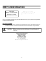
1
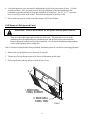
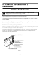
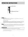
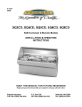
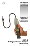
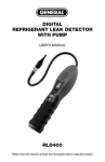
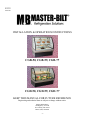
E3233
04/23/09
INSTALLATION & OPERATIONS INSTRUCTIONS
CGB-50, CGB-59, CGB-77
CGD-50, CGD-59, CGD-77
KEEP THIS MANUAL FOR FUTURE REFERENCE
Engineering and technical data are subject to change without notice.
Master-Bilt Products
908 Highway 15 North
New Albany, MS 38652
Phone: (800) 684-8988
-1-
CONTENTS
INTRODUCTION....................................................................................................................................... 3
WARNING LABELS & SAFETY INSTRUCTIONS ............................................................................. 4
PRE-INSTALLATION PROCEDURES .................................................................................................. 5
Inspection For Shipping Damage................................................................................................ 5
INSTALLATION INSTRUCTIONS......................................................................................................... 5
Locating The Display Case ......................................................................................................... 5
Removing Case From Shipping Skid.......................................................................................... 5
Grill Removal.............................................................................................................................. 6
Condensate Evaporator ............................................................................................................... 7
Cleaning ...................................................................................................................................... 7
Refrigeration Installation ................................................................................................................. 7
ELECTRICAL INFORMATION & GROUNDING ............................................................................... 8
OPERATING INSTRUCTIONS ............................................................................................................... 9
Controls....................................................................................................................................... 9
Shelves ........................................................................................................................................ 9
Rear Package Shelf ..................................................................................................................... 9
Doors........................................................................................................................................... 9
Placing Product Into Case ......................................................................................................... 10
SHELVING INSTALLATION & REMOVAL.................................................................................11-13
Shelves and shelf light quantity ................................................................................................ 13
SHELF INSTALLATION........................................................................................................................ 13
Wire Shelves ............................................................................................................................. 13
Metal Shelves............................................................................................................................ 13
MAINTENANCE ...................................................................................................................................... 14
Shelf Light Bulb Replacement .................................................................................................. 14
Top Light Bulb Replacement .................................................................................................... 14
PERIODIC MAINTENANCE ................................................................................................................. 15
Cleaning Condenser Coil .......................................................................................................... 15
CLEANING INSTRUCTIONS...........................................................................................................16-18
Daily Cleaning .......................................................................................................................... 16
Weekly Cleaning....................................................................................................................... 17
Interior Cleaning ..................................................................................................................17-18
Exterior Cleaning ...................................................................................................................... 18
SERVICE INFORMATION .................................................................................................................... 19
Pre-Service Checklist................................................................................................................ 20
Special Service Situations ......................................................................................................... 21
SALE & DISPOSAL................................................................................................................................. 21
Owner Responsibility............................................................................................................ 2129
REFRIGERATION & ELECTRICAL DATA ...................................................................................... 22
MAIN WIRING DIAGRAMS ................................................................................................................. 23
LIGHT WIRING DIAGRAMS ..........................................................................................................24-26
REPLACEMENT PARTS ....................................................................................................................... 27
-2-
INTRODUCTION
Thank you for purchasing a Master-Bilt cabinet. This manual contains important instructions for
installing and servicing the Master-Bilt Curved Glass Display Cases. A repair parts list and wiring
diagram are also included in the manual. Read all of these documents carefully before installing or
servicing your case.
NOTICE
Read this manual before installing your case. Keep this manual and refer to it before doing any
service on the equipment. Failure to do so could result in personal injury or damage to the
case.
NOTICE
Installation and service of the electrical components in the case must be performed by a
licensed electrician.
The portions of this manual covering components contain technical instructions intended only for
persons qualified to perform electrical work.
DANGER
Improper or faulty hookup of electrical components in the case can result in severe injury or
death.
All electrical wiring hookups must be done in accordance with all applicable local, regional, or
national standards.
SERIAL NUMBER
Record the model and serial numbers of the case for easy reference. Always refer to both model and
serial numbers in your correspondence regarding the case.
Case Model__________________________ Serial Number______________________
Condensing Unit Model________________ Serial Number______________________
This manual cannot cover every installation, use, or service situation. If you need additional
information, call or write us:
Technical Service Department
Master-Bilt Products
Highway 15 North
New Albany, MS 38652
Phone: (800) 684-8988
Fax: (866) 882-7629
Email: [email protected]
-3-
WARNING LABELS & SAFETY
INSTRUCTIONS
This is the safety-alert symbol. When you see this symbol on your case or in the
manual, be alert to the potential for personal injury or damage to your equipment.
Be sure you understand all safety messages and always follow recommended precautions and safe
operating procedures.
NOTICE TO EMPLOYERS
You must make sure that everyone who installs, uses, or services your case is
thoroughly familiar with all safety information and procedures.
Important safety information is presented in this section and throughout the manual. The
Following signal words are used in the warning and safety messages:
DANGER:
Severe injury or death will occur if you ignore the message.
WARNING: Severe injury or death can occur if you ignore the message.
CAUTION:
Minor injury or damage to your case can occur if you ignore the message.
NOTICE:
This is important installation, operation, or service information. If you ignore the
message, you may damage your case.
The warning and safety labels shown throughout this manual are placed on your Master-Bilt
case at the factory. Follow all warning label instructions. If any warning or safety labels become lost or
damaged, call our customer service department at (800) 684-8988 for replacements.
CAUTION
HAZARDOUS MOVING PARTS
DO NOT OPERATE UNIT WITH
DISPLAY PANS REMOVED.
CAUTION
RISK OF ELECTRIC
SHOCK DISCONNECT
POWER BEFORE
SERVICING UNIT.
91-12340
This label is located on the back of the display case.
This label is located below the display pan.
-4-
PRE-INSTALLATION PROCEDURES
Inspection for Shipping Damage
You are responsible for filing all freight claims with the delivering truck line. Inspect all cartons
and crates for damage as soon as they arrive. If damage is noted to shipping crates, cartons, or if
a shortage is found, note this on the bill of lading (all copies) prior to signing.
If damage is discovered when the case is uncrated, immediately call the delivering truck line and
follow up the call with a written report indicating concealed damage to your shipment. Ask for
an immediate inspection of your concealed damage item. Crating material must be retained to
show the inspector from the truck line.
INSTALLATION INSTRUCTIONS
Locating the Display Case
The case should be located where it is not subjected to the direct rays of the sun, heating ducts,
grills, radiator, or ceiling fans, nor should it be located near open doors or main door entrances.
Also, avoid locations where there are excessive air movement or air disturbances.
The condenser air inlet and discharge is located at the rear of the case. Do not block this inlet
and do not locate the air inlet near a source of heat.
Removing Case From Shipping Skid
CAUTION: Do not push against the top glass, front glass, end glass, doors or
door frames when removing the case from the skid or moving the case. Case
damage or glass breakage could result.
1. Remove crate top and sides and note missing or damaged items as explained in the pre-installation
procedures outlined above.
2. Move the case as near as possible to the final location and before removing it from the shipping skid.
3. If your case is supplied with plastic end panels, remove them by lifting them in an upward direction.
Set these end panels aside to be reinstalled after case is placed in proper position.
4. Remove the (4) brackets that secure the case to the shipping skid.
5. Lift case off of skid and into required position.
-5-
6. Level and square the case as needed by adjusting the leg leveler in each corner of base. (Use the
wrench provided.) (The case must be level for proper drainage of defrost condensate to the
condensate evaporator and allow for proper alignment of front glass.) The 59”, & 77” cases also
have a set of leg levelers in the center. These must be adjusted so the base is flat.
7. The leveled case must be sealed to the floor using a NSF Listed Sealant.
Grill Removal (Refrigerated Units)
DANGER: Electric shock hazard. Do not operate unit with panels removed.
There is a removable slotted panel at the rear of the case. The panel allows access to the
condensing unit, the light ballast, the condensate pan, and the field wiring connection box.
Remove this panel to make field wiring connections. See electrical information and grounding
section of this manual before wiring case.
Note: If electrical connection has been performed, disconnect power to case before removing grill panel.
1. Remove the rear grill panel screws from top of rear grill.
2. Tilt the top of rear grill panel outward as shown in illustration on the right.
3. Pull rear grill panel tabs up and out of slots in base of case.
2.
1. REAR GRILL
PANEL SCREWS
3. REAR GRILL
PANEL TABS
-6-
E1954-7
Condensate Evaporator
This case is furnished with an electrical condensate evaporator. Plumbing connections are not
required.
The condensate evaporator is located toward the front of the machine compartment and is
accessible from the rear of the case. After removal of rear grill panel, make sure that the drain
line has not been dislodged during shipment and that the drain trap is located properly over the
water reservoir of the condensate evaporator pan.
Cleaning
For initial setup, clean the case as outlined in the weekly cleaning section of this manual.
Refrigeration Installation
Self Contained Models
The self-contained models are shipped from the factory with a completely operational 134A
refrigeration system and require no modifications or adjustments upon installation.
-7-
ELECTRICAL INFORMATION &
GROUNDING
This Case Must Be Grounded
DANGER: Improper or faulty hookup of electrical components in the
display case can result in severe injury or death.
Only a licensed electrician must perform all case electrical connections.
All electrical wiring hookups must be done in accordance with all applicable local, regional, or national
electrical standards.
A separate circuit for each display case is recommended to prevent other appliances on the same circuit
from overloading the circuit and causing malfunction.
The electrical service must be grounded upon installation.
This unit is designed for permanent connection to a power source. See the electrical data plate located at
the rear of the case for proper circuit size and wire ampacity.
The electrical connection box is accessible from the rear of the case. Remove rear grill on refrigerated
models. (See “Grill Removal” in the installation section of this manual.) See diagram below for
location of the field wiring connection box.
BACK OF CASE OVERHANGS
BASE 1".
7/8" DIA. ELECTRICAL ENTRANCE
ON REAR OF CASE,
1" FROM SIDE OF BASE
1-3/4" FROM BOTTOM OF BASE
7/8" DIA. ELECTRICAL ENTRANCE
IN BOTTOM OF CASE,
2-3/4" FROM SIDE OF BASE,
2-1/8" FROM REAR OF BASE.
FIELD CONNECTION COVER
FOR REFRIGERATED CASES
E3233-1
-8-
OPERATING INSTRUCTIONS
LIGHT SWITCH
TEMPERATURE CONTROL
E1954-8
Controls
Light Switch
This switch controls the power to the lighting circuit. The switch rocker is red in the “on”
position, black in the “off” position.
Temperature Control
This controls the refrigerated side by cycling the compressor/condensing unit. It has an “off”
position and the coldest setting when the knob is set all the way in the clockwise position. Set
this control at the lowest setting possible, while maintaining desired case temperature.
Shelves
Each display is furnished with shelves that are adjustable up and down and can be tilted in three
angular positions. See “Shelving Installation & Removal” section of this manual for proper
installation, adjustment and removal of shelving.
Sliding Rear Doors
The doors can be easily removed by lifting doors upward until the bottom edge of door clears the
lower track. Swing the bottom of door outward and down out of top track.
Clean the door track frequently for easy door operation. A Very light film of lubricant, such as
PAM, will help the doors slide easily.
-9-
Placing Product into Case
After completing shelving installation as outlined in “Shelving Installation and Removal” section
of this manual you may begin placing product into the display case.
- Do not exceed 150 pounds of weight per shelf. Heavy product should be distributed evenly
across the entire shelving area.
- Determine desired shelving location and angle before placing product in case. Product must be
removed to readjust shelf location and angle.
- Do not overhang the front of wire shelves with product. Product may overhang rear of shelf,
but allow a minimum of 1-1/2” between product and rear door. Improper clearance in front and
rear of shelf will block the refrigerated airflow and could cause product loss.
-Do not block the slots along the front or rear of the case display pan. Covering these slots will
block the refrigerated airflow and could cause product loss.
-The display pan is removable for cleaning and can become dislodged in shipment. To ensure
proper airflow and performance of the case, make sure that the display pan is pushed completely
down into evaporation tub. Check that the pan is installed properly before placing product the
display pans.
-Allow refrigerated models to run for at least two hours before placing pre chilled product into
unit. Turn temperature control to the lowest possible position that maintains required interior
cabinet temperature.
-CASE SHOULD BE STOCKED WITH PRE-CHILLED PRODUCT
ONLY.
ATTENTION:
- Refrigerated display cases are designed to operate in a maximum
environment of 75 DEG. F and 55% relative humidity. Exceeding these
limits could cause poor case performance and sweating of glass
panels.
- 10 -
SHELVING INSTALLATION & REMOVAL
FEMALE SHELF
LIGHT SOCKET
METAL SHELF
WIRE SHELF
WIRE RETAINER
CLEAR PLASTIC
CLIP
SHELF BRACKET
SHELF LIGHT
SHELF SUPPORT
SHELF RETAINER
CLEAR PLASTIC CLIP
WIRE SHELF ONLY
SHELF BRACKET
1. Turn the light switch to the off position, on units with sliding rear doors, remove both rear doors
from track by lifting doors upward until the bottom edge of door clears the lower track. Swing the
bottom of door outward and down out of top track.
2. Insert a shelf bracket in the desired shelf standard slot on one side of case. The short set of shelf
brackets are for the top shelf and the longer shelf brackets are for the middle and bottom shelves.
Follow the instruction in the illustration below. Place an additional shelf bracket in the same shelf
standard slot on the opposite end of case. Repeat for additional shelf tiers.
- 11 -
INSTALLATION
SHELF STANDARD
TOP HOOK
REMOVAL
SHELF BRACKET
1
1
2
2
3
BOTTOM TAB
3
4
4
E1954-3
12° NOTCH
6° NOTCH
0° NOTCH
A.. Place shelf bracket top hook into desired shelf
standard slot.
B. Lift shelf bracket top hook to allow shelf bracket
bottom tab to clear shelf standard slot.
C. Swing shelf bracketbottom tab into shelf standard
slot.
D. Place the desired shelf bracket notch of 0, 6, or 12
degrees onto bottom of shelf standard slot.
A. Lift shelf bracket up to allow shelf bracket notch
to clear the bottom of shelf standard slot.
B. Swing shelf bracket bottom tab out of shelf
standard slot.
C. Drop shelf bracket down to allow shelf bracket top
hook to clear top of shelf standard slot.
D. remove shelf bracket top from shelf standard slot.
3. Hang one end of shelf light housing on the front notch of a shelf bracket and then the other end of
shelf light housing on the notch of the shelf bracket on the opposite end. Repeat for each additional
shelf tiers
4. Push shelf light cords into clear plastic clip located on inside of shelf brackets.
5. Remove the cap from the appropriate female light sockets. If socket is not being used for a shelf
light, the cap must be plugged into socket for entire light system to operate. NOTE: Grip each side
of cap firmly and wiggle and pull cap straight out of socket. Do not roll cap during removal.
RIGHT
WRONG
6. Plug in each shelf light by aligning the male pins on the appropriate shelf light cord plugs with the
female light sockets and push together. NOTE: Do not roll plug during insertion.
- 12 -
7. Hang one end of the shelf support on to the rear notch of one shelf bracket and then on the rear notch
of the shelf bracket on the opposite side. Repeat for additional shelf tiers.
8. Place supplied shelving onto shelf supports as outlined in the appropriate “Shelf Installation” section
of this manual.
9. On units with sliding rear doors, re-install both rear doors by lifting top of door into top track and
swinging bottom of door onto bottom track. Install door labeled “inner door” first on inner track and
door labeled “outer door” second on outer track.
Shelves and shelf light quantity
It is not required that all shelves and shelf lights supplied with each case are used. The quantity of
shelves and shelf lights can be tailored to your specific needs. If the supplied quantity of shelves and
shelf lights are not required, cap unused female socket located in interior of the case mullion with caps
supplied. Failure to do so will prevent entire lighting system from operating.
SHELF INSTALLATION
Wire Shelves
1. The CGB models are provided with 22” wire shelves for the bottom and middle shelf and the 16”
wire shelf is for the top shelf.
2. With rear sliding doors removed place front of wire shelf onto front shelf light and snap the front of
shelf into the clear plastic clips on front light housing.
3. Snap the rear of shelf into the clear plastic clips on rear shelf support.
4. Repeat 2 & 3 for each tier.
NOTE: Units with 73” long rear shelf supports uses (2) wire shelves per tier. All other units use (1)
wire shelf per tier.
Metal Shelves
1. The CGD models are provided with a single metal shelf.
2. With rear sliding door removed, or rear swing door open, place front of metal shelf on to front shelf
light.
3. Set the rear of the metal shelf on to the rear shelf support so that the notch at each end of metal shelf
straddles the rear shelf support. If clear plastic clips were factory-installed on top of rear shelf
support or front shelf light, remove and discard clear plastic clips.
4. Repeat steps 2 & 3 for each tier if supplied with more than (1) tier of shelving.
- 13 -
MAINTENANCE
Shelf Light Bulb Replacement
1. All shelf light fixtures use a spring-loaded socket at one end. To remove the bulb push the bulb
towards the spring-loaded socket until the opposite ends drops out of the socket.
2. The bulb is inside a clear shatter proof tube with a black plastic cap on each end. Be careful not
to allow bulb to slide out of shatter proof tube.
3. Reinstall new bulb in to the existing shatter proof tube and reuse black plastic end caps. Reinstall
bulb assembly in the same manner as described in the Bulb Removal Procedure. Be sure bulb is
secure in bulb receptacles
Note: Be sure to use a direct equivalent to the original bulb.
Top Light Bulb Replacement
1. On units with sliding rear doors, remove both rear doors from track by lifting doors upward until the
bottom edge of door clears the lower track. Swing the bottom of door outward and down out of top
track. On units with rear swing doors completely open doors to allow access to interior of case.
2. Remove all shelves, shelf supports and Shelf lights from unit through rear door opening. (See
“Shelving Installation and Removal” section of this manual for instruction if needed)
3. Remove top light lens clip screw(s), lens clip(s), and top light lens as illustrated below.
4. To remove bulb from top light housing, grip the bulb receptacle end caps at each end of bulb. Pull
the bulb receptacle end caps straight outward toward front of case. Once bulb and bulb receptacle
end caps are removed from top light housing remove the bulb receptacle end caps from end of bulb.
(Note: 50”dual zone models do not have end caps.)
5. Reinstall new bulb in the same manner as described in the Bulb Removal Procedure. Be sure bulb is
secure in bulb receptacles. Note: Be sure to use a direct equivalent to the original bulb.
6. Reinstall top light lens, lens clips, and lens clip screws in reverse order as shown in illustration
below.
BULB END CAPS
TOP LIGHT LENS
2
1
LENS CLIP SCREW(S)
LENS CLIP(S)
4
BULB END CAPS
3
TOP LIGHT LENS
E1954-4
- 14 -
PERIODIC MAINTENANCE
Cleaning Condenser Coil
It is very important that the Condenser coil is cleaned twice per month to insure proper
refrigeration performance and to prevent compressor failure. Failure to clean condenser
coil will void condenser warranty.
1. Disconnect power to the unit.
2. Remove the back base panel located on the back bottom of unit by removing the panel retaining
screws.
3. Carefully vacuum the front surface of condenser coil. Take care not to bend coil fins with
vacuum cleaner nozzle.
4. Reinstall back panel and retaining screws.
VACCUM
CONDENSER
COIL FINS
AIR INTAKE
REAR PANEL
- 15 -
CLEANING INSTRUCTIONS
Daily Cleaning
The case should be cleaned thoroughly, as described in the weekly cleaning section, before it is
used for the first time.
NOTICE:
Avoid splashing or soaking any electrical components with water to
prevent electrical damage to the case.
NOTICE:
Shut off lights and power switches and remove all product from case.
Allow sufficient time for the unit to reach room temperature before
proceeding with cleaning.
NOTICE:
Remove all product from case before proceeding with cleaning
procedure.
Note: For major spills or foreign material buildup use complete weekly cleaning instructions.
1. Clean all foreign materials from the door opening.
2. Wipe complete interior of case using a damp cloth.
3. Tilt the front glass forward as described in the illustrations below. This will allow easier
access to clean interior front and side glass. The glass can then be cleaned with common
window cleaners.
OPEN FRONT GLASS:
1. Stand in front of unit and grab the pull
handle with both hands.
2. Pull front glass outward until the glass
rests on front glass stops.
CLOSE FRONT GLASS:
1. Stand in front of unit and push on front
of pull handle with both hands.
2. Firmly push glass towards rear of unit
until front glass rests in closed position
4. The remaining exterior surface should be wiped down using any soapy warm water.
Note: Do not use detergents or chlorine and do not use abrasive cleaners or pads to prevent
scratching of surfaces.
- 16 -
Weekly Cleaning
This procedure is recommended on a weekly basis. It may need to be performed more often if
necessary to maintain a clean, sanitary case. The case should be cleaned to this procedure before
using the first time.
NOTICE:
Avoid splashing or soaking any electrical components with water to
prevent electrical damage to the case.
NOTICE:
Shut off light and power switches and remove all product from case. Allow
sufficient time for the unit to reach room temperature before proceeding
with cleaning.
Interior Cleaning
REAR DOOR
OUTER
REAR DOOR
INNER
REFRIGERATED
MODELS ONLY
SHELVING
E1954-9
SHELF
SUPPORT
FAN SHROUD
MOUNTING TABS
EVAP. FAN
SHELF BRACKET
SHELF
LIGHT
DISPLAY PAN
EVAP FAN SHROUD
- 17 -
SHELF STANDARD
1.
Remove all interior shelving as described in the shelving installation and removal section of this
manual.
2.
Remove both shelf standards from interior of case. First remove thumbscrew at bottom of shelf
standard and then slide shelf standard up to allow top key slot to clear.
3.
Lift the display pan up and out of evaporator tub. Remove display pan through rear opening.
4.
Remove the evaporator fan shroud. First remove the thumbscrews along the backside of
evaporator fan shroud. Lift the rear of the evaporator fan shroud allowing the front to hinge on
fan shroud mounting tabs. Reach in and unplug the evaporator fan motor cord. Continue to lift
the evaporator fan shroud while at the same time pulling it to the door opening of case until the
slots in the evaporator fan shroud can clear the fan shroud mounting tabs. Remove evaporator
fan shroud through rear opening.
5.
Clean the entire interior of the case using warm soapy water. Wipe off all soapy water with a
damp cloth and allow todry.
NOTE: Depending on the amount of usage and spillage of foreign material, some fasteners may have to
be removed and parts disassembled to allow proper cleaning of the unit.
6.
Clean all shelves, shelf support bars, shelf light housings, shelf light housings, shelf brackets,
and display pans using warm soapy water and a brush. Rinse thoroughly and allow to dry.
7.
Clean all foreign material from inner and outer rear door tracks using warm soapy water and a
brush. Apply a light film of lubricant such as PAM to make the doors operate smoother.
8.
Clean both sides of the doors and interior of the front glass using any common window cleaner.
NOTE: Front glass can be tilted forward to simplify front glass cleaning. See “Daily Cleaning” section
for glass tilting operation.
9.
Reassemble the case in reverse order starting with Step 6.
Exterior Cleaning
1.
Clean the front glass using any common window cleaner.
2.
The exterior surfaces should be wiped down using any ammoniated cleansers or warm soapy
water.
NOTE: For major spills or foreign material build-up use complete weekly cleaning instruction.
- 18 -
SERVICE INFORMATION
CAUTION
RISK OF ELECTRIC SHOCK
DISCONNECT POWER
BEFORE SERVICING UNIT
Before any service work is
performed on the case, make sure all
power is disconnected to the case.
Service problems or request for repair parts from authorized service agencies, trained service personnel,
or owners should be referred to:
Pre-Service Checklist
You may avoid the cost and inconvenience of an unnecessary service call by first reviewing this
checklist of frequently encountered situations that can cause unsatisfactory case performance.
CAUTION:
Before servicing case turn off power at the main breaker of
fuse box.
Technical Service Department
Master-Bilt Products
Highway 15 North
New Albany, MS 38652
Phone: (800) 684-8988
Fax: (866) 882-7629
Email: [email protected]
- 19 -
Pre-Service Checklist
Case Does Not Operate
Check for disconnected power supply.
Check for tripped breaker or blown fuse.
Check that the thermostat is not “off”.
Lights Do Not Operate
Check that light switch is on.
Be sure light is properly seated in the sockets.
Check that light cord(s) are tight in the sockets.
Plug unused light sockets with socket cap provided with socket.
Case Temperature Too Warm
Check that the cold air inlet and outlet slots are not blocked.
Be sure that the rear doors are closed and tightly sealed.
Check for a blocked or dirty condenser coil filter or condenser coil fins.
Check cold airflow. Lack of adequate cold airflow could be a defective evaporator fan or
blocked evaporator coil. Check that paper or foreign material is not blocking evaporator.
If the evaporator coil is blocked due to excessive frost, turn the thermostat knob to the
“off” position for approximately one hour to defrost. Excessive frost will buildup if the
case is operated with the door open or ajar.
Check that the display pans are installed properly.
Glass Fogging
Check room ambient – Case is designed to operate in an environment not to exceed 75°F
and 55% relative humidity.
Check case temperature – Case is designed to operate between 38°F and 42°F.
Check that nothing is placed on the top of the case glass.
- 20 -
Special Service Situations
There are rare occasions when the refrigerant charge must be evacuated from a case in order to
perform service work. In those situations the refrigerant charge must be evacuated into a
recovery system to prevent the possibility of hydrofluorocarbons (HFC’s) from being released
into the atmosphere.
If moisture or liquid is observed around or under case, an immediate investigation should be
made by qualified personnel to determine the source of the moisture or liquid. The investigation
made should determine if the case is malfunctioning or if there is a simple housekeeping
problem.
Moisture or liquid around or under a case is a potential slip/fall hazard for persons walking by or
working in the general area of the case. Any case malfunction or housekeeping problem that
creates a slip/fall hazard around or under a case should be corrected immediately.
SALE & DISPOSAL
Owner Responsibility
If you sell or give away your Master-Bilt case you must make sure that all safety labels and the
Installation-Service Manual are included with it. If you need replacement labels or manuals,
Master-Bilt will provide them free of charge. Contact the technical service department at
Master-Bilt at (800) 684-8988.
The technical service department at Master-Bilt should be contacted at the time of sale or
disposal of your case so records may be kept of its new location.
If you sell or give away your Master-Bilt case and you evacuate the refrigerant charge before
shipment. Master-Bilt recommends that the charge be evacuated into a recovery system to
prevent the possibility of HFC’s from being released into the atmosphere.
- 21 -
REFRIGERATION & ELECTRICAL DATA
REFRIGERATION
&
ELECTRICAL
DATA
REFRIGERANT
R-134 (OZ)
LIGHTS
EVAPORATOR CONDENSATE COMPRESSOR TOTAL
FAN MOTOR
PAN HEATER
RLA
LRA
AMPS
REFRIGERATED SELF CONTAINED
CGB-50
28
0.7
0.4
1.2
8.8
58.8
CGB-59
32
0.9
0.4
1.2
8.8
58.8
CGB-77
36
1.3
0.8
1.2
10.1
68
CGD-50
28
0.7
0.4
1.2
8.8
58.8
CGD-59
32
0.9
0.4
1.2
8.8
58.8
CGD-77
36
1.3
0.8
1.2
10.1
68
Refer to the data plate attached to rear of the case for maximum fuse size and minimum circuit ampacity.
- 22 -
10.5
11.6
14.2
10.5
11.6
14.2
MAIN WIRING DIAGRAMS
120 VOLT REFRIGERATED SELF CONTAINED
MAIN WIRING DIAGRAM
DETAIL
DOOR TRIM HEATER
BLK
BLK
CONDENSATE
EVAPORATOR
REAR SWING DOOR UNITS ONLY
BLK
EVAP.
FAN
MOTOR
M
BLK/RIB
BLK
(HEATER)
BLK/RIB
(HEATER) BLK/RIB
BLK
EVAP.
FAN
MOTOR
M
BLK
(SWITCH)
BLK
BLK/RIB
BLK/RIB
BLK
LIGHT
SWITCH
(BALLAST)
(SEE LIGHT WIRING
DIAGRAM DETAIL)
W
G
TO LIGHT
BALLAST
CONDENSER
RECEPTACLE
HIGH PRESS.
CUTOUT
BLK
BLK/RIB
INCLUDED ON 77" UNITS ONLY
ON 36,59DZ
& 77DZ ONLY
BLK
BLK
(THERM.)
W
G
BLK/RIB (THERM.)
91-14146
12/22/98
BLK
W
L1
N
CONDENSINGUNI
T
FIELD
CONNECTION
BOX
GND
SEE DIAGRAM
IN COMP.
FOR DETAILS.
G
CORD
120 VOLTS
60 HERTZ
1 PHASE
UNIT MUST BE GROUNDED
- 23 -
COLOR CODE
BLK = BLACK
W = WHITE
R = RED
B = BLUE
Y = YELLOW
G = GREEN
LIGHT WIRING DIAGRAMS
CGD-50, CGD-59 & CGD-77
LIGHT WIRING DIAGRAM
DETAIL
(2) F017T8, FO25T8, FO32T8, FO40T8
TOP LIGHT
B (T1)
R (T1)
LAMP
G
W (BALLAST)
W
BLK
TO LIGHT SW.
TO GROUND
BALLAST
(BALLAST) BLK
(SWITCH) BLK
G
B
R
B
(A)
(A)
RECP.&
PLUG
R
R (S1)
B (S1)
B
BLK (B)
BLK
G
G
SHELF LIGHT
LAMP
(SEE MAIN WIRING DIAGRAM DETAIL)
91-13924
04/16/01
COLOR CODE:
BLK = BLACK
W = WHITE
R = RED
- 24 -
B = BLUE
Y = YELLOW
G = GREEN
CGB-50 & CGB-59
LIGHT WIRING DIAGRAM
DETAIL
(4) FO15T8,F017T8, FO25T8, FO32T8
TOP LIGHT
B (T1)
R (T1)
LAMP
G
RECP.&
B (S1) PLUG R
R (S1)
B
BLK
BLK
G
ONLY 1 YELLOW
ON F15 BALLAST
ALL BL TO Y
LAMP
G
RECP.&
PLUG
R (S2)
R
B (S2)
B
Y
W (BALLAST) W
BLK
Y
BALLAST
R
R
B (R)
B (R)
BLK
BLK
G
TO LIGHT SW.
TO GROUND
(A)
(BALLAST)
(SWITCH) BLK
G
(A)
BLK
(SEE MAIN WIRING DIAGRAM DETAIL)
(R) (R) FOR FO15
91-13927
5/7/08
- 25 -
BLK
BLK
G
SHELF LIGHT
LAMP
G
RECP.&
R (S3)PLUG R
B (S3)
SHELF LIGHT
SHELF LIGHT
B
LAMP
G
COLOR CODE:
BLK = BLACK B = BLUE
W = WHITE
Y = YELLOW
R = RED
G = GREEN
CGB-77
LIGHT WIRING DIAGRAM
DETAIL
TOP LIGHT
(4) F040T8
B (T1)
R (T1)
LAMP
G
CAP BLUE LEADS NOT USED
W
B
BALLAST R
BLK
B
RECP.&
R (S1) PLUG R
B (S1)
B
BLK
BLK
G
G
RECP.&
PLUG
B (S2)
B
R (S2)
R
BLK
BLK
G
G
W (BALLAST)
BALLAST
TO LIGHT SW.
TO GROUND
BLK
(BALLAST)
(SWITCH)
B
R
B
(A)
BLK
G
(SEE MAIN WIRING DIAGRAM DETAIL)
91-13928 04/16/01
- 26 -
RECP.&
R (S3) PLUG R
(A)
B (S3)
BLK
BLK
G
SHELF LIGHT
LAMP
SHELF LIGHT
LAMP
SHELF LIGHT
B
LAMP
G
COLOR CODE:
BLK = BLACK B = BLUE
W = WHITE
Y = YELLOW
R = RED
G = GREEN
REPLACEMENT PARTS
ELECTICAL COMPONENTS
MODELS
CGB-50
CGD-50
CGB-59
CGD-59
CGB-77
CGD-77
LIGHT
SWITCH
LIGHT
BALLAST
41-11066
41-11066
41-11066
41-11066
41-11066
41-11066
39-12904
39-12902
39-12904
39-12902
39-12903
39-12903
LIGHT BULB LIGHT BULB
SHELF LIGHT
SHELF LIGHT
CAP
RECEPT.
CORD
HARNESS
42-11069
42-11069
42-11070
42-11070
42-11071
42-11071
42-15441
42-15441
42-15441
42-15441
42-15441
42-15441
43-15888
43-15888
43-15888
43-15888
43-15888
43-15888
43-13920
43-13922
43-13920
43-13922
43-13920
43-13922
SHELF
LENS
LENS
42-14141
42-14141
42-14142
42-14142
42-14164
42-14164
TOP LIGHT
TOP LIGHT
WIRE
HARNESS
LENSE
LIGHT
WIRING
DIAGRAM
SC MAIN
WIRING
DIAGRAM
43-15889
43-15889
43-15889
43-15889
43-15889
43-15889
91-13927
91-13924
91-13927
91-13924
91-13928
91-13924
91-14146
91-14146
91-14146
91-14146
91-14146
91-14146
42-13643
42-13643
42-13644
42-13644
42-13645
42-13645
GLASS COMPONENTS
MODELS
CGB-50
CGD-50
CGB-59
CGD-59
CGB-77
CGD-77
CURVED END GLASS END GLASS END GLASS
FRONT
FRONT
CLEAR
REFL. L.H.
REFL. R.H. GLASS EDGE
GLASS
SEAL 3'
50-18936-3
50-18936-3
50-18936-4
50-18936-4
50-18936-5
50-18936-5
50-18938
50-18938
50-18938
50-18938
50-18938
50-18938
50-18938-L
50-18938-L
50-18938-L
50-18938-L
50-18938-L
50-18938-L
50-18938-R
50-18938-R
50-18938-R
50-18938-R
50-18938-R
50-18938-R
64-13122
50-18938-R
50-18938-R
50-18938-R
50-18938-R
50-18938-R
FILTER DRIER
THERMOSTAT
CONDENSATE
PAN ASSY
CONDENSATE
HEATER
30-15328
30-15328
30-15328
30-15328
30-15329
30-15329
EVAPORATOR
FAN BLADE
30-14218
30-14218
30-14218
30-14218
30-14219
30-14219
EVAPORATOR
FAN MOTOR
W/BLADE
CGB-50
CGD-50
CGB-59
CGD-59
CGB-77
CGD-77
CONDENSING UNIT
(SC) 120V (SC) 240V
EXPANSION
VALVE
MODELS
EVAPORATOR
COIL
REFRIGERATION COMPONENTS
33-13357
33-13357
33-13358
33-13358
33-13359
33-13358
32-12625
32-12625
32-12625
32-12625
32-12625
32-12625
41-13363
41-13363
41-13363
41-13363
41-13363
41-13363
72-12254
72-12254
72-12254
72-12254
72-12254
72-12254
32-12391
32-12391
32-12391
32-12391
32-12391
32-12391
32-15495
32-15495
32-15495
32-15495
32-15495
32-15495
SA-2134
SA-2134
SA-2134-1
SA-2134-1
SA-2134-1
SA-2134-1
40-13362
40-13362
40-13362
40-13362
40-13362
40-13362
DOOR & SHELF COMPONENTS
MODELS
CGB-50
CGD-50
CGB-59
CGD-59
CGB-77
CGD-77
DOOR LEFT DOOR RIGHT DOOR LEFT DOOR RIGHT WIRE SHELF WIRE SHELF WIRE SHELF SHELF STAINLESS SHELF
CLEAR
CLEAR REFLECTIVE REFLECTIVE WHITE TOP
WHITE
CLIP
LIGHT ASSY SHELF
BRACKET
MID/BTM
TOP
53-13676
53-13676
53-13676
53-13676
53-13680
53-13680
53-13677
53-13677
53-13677
53-13677
53-13681
53-13681
53-13692
53-13692
53-13692
53-13692
53-13696
53-13696
53-13693
53-13693
53-13693
53-13693
53-13697
53-13697
63-13815-2
N/A
63-13816-2
N/A
63-13817-2
N/A
- 27 -
63-13815-1
N/A
63-13816-1
N/A
63-13817-1
N/A
81-30618
N/A
81-30618
N/A
81-30618
N/A
SA4842-3
SA4842-3
SA4842-4
SA4842-4
SA4842-5
SA4842-5
N/A
M11558-1
N/A
M11558-2
N/A
M11558-3
67-14293
67-14293
67-14293
67-14293
67-14293
67-14293
SHELF
BRACKET
MID/BTM
67-15229
67-15229
67-15229
67-15229
67-15229
67-15229