1
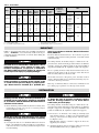
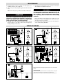
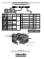
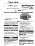
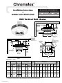
Installation Instructions
SERVICE REFERENCE
DIVISION
and
4
SECTION
SALES
REFERENCE
RENEWAL PARTS IDENTIFICATION
VUH
(Supersedes PF450-4)
PF450-5
161-057822-001
JULY, 2002
DATE
VUH Vertical Unit Heater
12" Min.
30" Min.
8-1/2"
4-11/16" Dia.
Mounting
Holes
3-7/8"
Drop
Ceiling
17"
Position With
Junction Box
Facing Away
From Walls
For Easy Access
30" Min.
F
Approx.
H
D
4-11/16" Dia.
Mounting
Holes
12" Min.
Anemostat**
Diffuser
Note:
Knockout Location
See Table 2
For Recommended
Conduit Size.
A
E
B
M
4-11/16" Dia.
Mounting Holes
7' Min.
To Floor
CL
Warm Air
Discharge
C
Figure 2
Figure 1
Specifications — Table 1
Heating Capacity
Model
Volts
1
3
Phase Phase
kW
BTUH
5
17,000
208
240
277
VUH-C-07 7.5
25,500
9.8
VUH-C-10 10
34,000
VUH-C-05
Air Delivery Data
Max.
Mtg.
Outlet Height
Temp.˚F* (Ft.)
CFM
FPM
208
240
480
450
703
102
208
240
277
208
240
480
550
880
208
208
240
277
240
480
712
1160
Dimensions (In.)
A
B
C
D
E
F
H
M
10
14
13-1/2
26
3-1/4
6-5/8
4
7-1/4
10-5/8
48
102
12
14
13-1/2
26
3-1/4
6-5/8
4
7-1/4
10-5/8
48
104
14
14
13-1/2
26
3-1/4
6-5/8
4
7-1/4
10-5/8
48
* Based on 60˚F entering air.
** For use with drop ceiling only. Installation in a drop ceiling should be in accordance with NFPA-90A and Article 300-22 of (NEC).
*** For instructions on VUH units rated 15-25 kW refer to Bulletin PF451; VUH units rated 30-50 refer to Bulletin PF452.
© 2010 Chromalox®, Inc.
Mtg.
Weight
(Lbs.)
Table 2 - Electrical Data
Power Supply Circuit
Model
kW
VUH-C-05
5
VUH-C-07
7.5
9.8
VUH-C-10
10
Volts
208
208
240
240
277
480
208
208
240
240
277
480
208
208
240
240
277
480
Phase
1
3
1
3
1
3
1
3
1
3
1
3
1
3
1
3
1
3
Notes:
1. Includes Fan Motor Amps.
2. Use 75˚C Wire - Copper Conductors only.
Line
Amps
(Note 1)
Line
Wire Size
(Note 2)
No.
Circuits
25
15
22
13
19
7
37
22
32
19
28
10
48
29
43
25
37
13
8
12
10
12
10
14
6
10
8
10
8
14
6
8
6
8
6
12
1
1
1
1
1
1
1
1
1
1
1
1
1
1
1
1
1
1
3.
†
Minimum
Conduit
Size †
3/4”
1/2”
1/2”
1/2”
1/2”
1/2”
3/4”
1/2”
3/4”
1/2”
3/4”
1/2”
3/4”
3/4”
3/4”
3/4”
3/4”
1/2”
Contactor
Holding Coil
Volt Ampheres
(Note 3)
Inrush
Sealed
60
9
60
9
60
9
Motor
Volts
208/240
280/240
208/240
208/240
277
480
208/240
208/240
208/240
208/240
277
480
208/240
208/240
208/240
208/240
277
480
H.P.
Phase
1/25
1
1/25
1
1/25
1
Standard units have one contactor. Units with separate fan
motor control use two contactors.
Conduit knockout location - top of Junction Box.
IMPORTANT
Failure to understand and follow these installation instructions
and the “WARNING” notes therein may result in serious personal injury from electrical shock, or from the heater falling due
to faulty installation.
FIRE/EXPLOSION HAZARD. This heater is not
intended for use in hazardous atmospheres where
flammable vapors, gases, liquids or other combustible atmospheres are present as defined in
the National Electrical Code. Failure to comply can
result in personal injury or property damage.
ELECTRIC SHOCK HAZARD. Disconnect all power
before installing or servicing heater. Failure to do
so could result in personal injury or property damage. Heater must be installed by a qualified per-
sonal in accordance with the National Electrical
Code, NFPA 70.
The heater must be mounted at least 7’ above the floor to prevent
accidental contact with the heating elements or fan blade which
could cause injury.
The ceiling structure, the brackets, hangers or chains used to suspend the heater, and the anchoring provisions must be of sufficient
strength to support the combined weight of the heater installation
(48 pounds for VUH-C-05, 07, 10 plus the weight of the supports).
Prior to operating the heater verify that the fan hub setscrews are
tightened and the push-on clip is secured to assure that the fan
blade is securely fastened to the motor shaft.
On models connected to three-phase power, fan blade rotation
must be checked. If airflow is not downward, interchange any two
of the three customer power leads.
First stage of thermostat must be connected to terminals C1 and
C2 to insure proper operation of overheat protective devices.
INSTALLATION
ELECTRIC SHOCK HAZARD. Any installation
involving electric heaters must be performed by a
qualified person and must be effectively grounded
in accordance with the National Electrical Code to
eliminate shock hazard.
The heater must be mounted at least
7’ above the floor to prevent accidental contact
with the heating elements or fan blade which
could cause personal injury.
1. Heater should be positioned with the junction box facing away
from walls to provide easy access for servicing relay(s)
mounted within. See Figure 1.
The ceiling structure, the brackets, hangers or chains used to suspend the heater and the anchoring provisions must be of sufficient
strength to support the total weight of the heater installation (48
pounds for VUH-C-05, 07, 10 plus the weight of the supports).
Mount the heater for down discharge only. Failure
to comply may result in personal injury or property
damage.
3. The heater to be mounted to the ceiling by attaching rigid
angle brackets, hangers, or chains to the four mounting holes
on the top of the heater case using four 5/8” bolts (by others).
See Figures 1 and 2.
Note: Brackets, hangers, or chains to support the heater are
supplied by the customer.
2. It is important that the 12” minimum dimension shown in
Figure 1 be maintained to make it possible for a serviceman to
remove the fan motor, if necessary, without moving the heater
from its mounting.
4. All wiring should be done in accordance with local codes and
the National Electrical Code by a qualified person.
MAINTENANCE
5. Rough-in wiring to heater. See Table 2 for line amperes, recommended wire size and conduit size.
6. Wire heater per wiring diagram supplied with this instruction
sheet.
8. Air diffusers for deflecting the air are optional. See Instruction
Sheet PF449 for installation instructions.
Note: Power relay(s) are provided as standard on all heaters.
ELECTRIC SHOCK HAZARD. Disconnect all power
to heater before servicing or replacing heaters. Do
not attempt to service heater while unit is operating as there is hazard of electric shock, injury
from operating fan, and burns from hot heating
elements.
Prior to operating the heater, verify that the fan hub
setscrews are tightened and the push-on clip is
secured to assure that the fan blade is securely fastened to the motor shaft. Failure to comply could
result in personal injury or property damage.
7. Carefully inspect the completed installation. Rotate the fan
blade by hand to be sure that it turns freely. Investigate any
binding, rubbing or interference.
1. Before activating for next heating season, vacuum or use compressed air to remove accumulated dust or lint, which otherwise may restrict proper air flow.
2. Periodically check all electrical connections and retighten to
avoid electrical wiring difficulties.
WIRING DIAGRAMS
Transformer Color Code Index
PRI XFMR 120V SEC. 24V SEC.
LEAD CLRS LEAD CLRS LEAD CLRS
VOLT
H1
208 BLK
240 BLK
277 BLK
H2
RED
ORG
X1
X2
BLK WHT
BLK WHT
BLK WHT
X1
YEL
YEL
X2
BLU
BLU
YEL
BLU
480 BLK BLK/RED BLK WHT
YEL
BLU
BRN
208 - 240V Motor
Hook-Up
Elements
Customer Wiring
Factory Wire
277V Motor
Hook-Up
208 - 240V Motor
Hook-Up
Elements
277V Motor
Hook-Up
BLU
BLK
BLU
BLK
M
M
M
BLK
WHT
RED
T2
T1
YEL
WHT
RED
BLK
T2
T1
YEL
480V Motor
Hook-Up
480V Motor
Hook-Up
Cutout
BLK
M
BLK
Cutout
RED
RED
Contactor
X1
T2 T3
T1
C1
L1 L2 L3
BLK
M
3ø Jumper
Hook-Up
XFMR
Fusing
Optional
XFMR
L1 L2 L3 T4
To Contactor
1ø Jumper
Hook-Up
TB2 C1 C2
TB1
Thermostat
(By Others)
L1 L2 L3 T4
Fused Switch
(By Others)
Customer Wiring
Factory Wire
Figure 3
Transformer Color Code Index
277V Motor
Hook-Up
VOLT
BLU
BLK
M
BLK
BLK
M
T2
T1
WHT
RED
YEL
480V Motor
Hook-Up
Cutout
BLK
T1
T2 T3
C1
L1 L2 L3
M
H1
208 BLK
240 BLK
277 BLK
H2
RED
ORG
BRN
X1
X2
BLK WHT
BLK WHT
BLK WHT
X1
YEL
YEL
YEL
X2
BLU
BLU
BLU
480 BLK BLK/RED BLK WHT
Customer Wiring
Factory Wire
YEL
BLU
277V Motor
Hook-Up
208 - 240V
Motor
Hook-Up
Elements
BLU
BLK
M
BLK
M
WHT
BLK
T1
Thermostat
(By Others)
YEL
YEL
480V Motor
Hook-Up
RED
XFMR
X1
X2
T1
C1
L1
T2 T3
1ø Power
BLK
L1 L2 L3
H1
Heat
H2
Fan
TB2 C2 C1
3ø Jumper
Hook-Up
XFMR
Fusing
Optional
YEL
WHT
T2
To Contactor
1ø Jumper
Hook-Up
L1 L2 L3 T4 TB1
Optional Heat Recovery Switch
(By Others)
BLU
M
C3
L2 L3
L1 L2 L3 T4 TB1
Fused Switch
(By Others)
T1 T2 T3
T1
C4 TB2
3ø
Power
60 HZ
Contactor
Cutout
2 PDT Switch
(By Others)
Thermostat
(By Others)
T2
To Contactor
1ø Jumper
Hook-Up
TB1
L1 L2 L3 T4
T2
T1
RED
BLU
WHT
3ø Jumper
Hook-Up
3ø
Power
60 HZ
Fused Switch
(By Others)
L1 L2 L3 T4 TB1
1ø Power
Figure 6
Figure 5
Customer Wiring
Factory Wire
PRI XFMR 120V SEC. 24V SEC.
LEAD CLRS LEAD CLRS LEAD CLRS
RED
Contactor
TB2 C1 C2
1ø Power
Figure 4
208 - 240V Motor
Hook-Up
Elements
L1 L2 L3 T4 TB1
Fused Switch
(By Others)
1ø Power
Customer Wiring
Factory Wire
1ø Jumper
Hook-Up
3ø
Power
60 HZ
Control
Power
(By Others)
L1 L2 L3 T4 TB1
To Contactor
TB1
3ø
Power
60 HZ
Thermostat
(By Others)
YEL
T2
T1
3ø Jumper
Hook-Up
TB2 C1 C2
BLU
M
WHT
T2
T1
H2
BLK
T1
T2 T3
C1
L1 L2 L3
Contactor
YEL
WHT
X2
H1
BLU
208 - 240V
Motor
Hook-Up
Elements
BLU
BLK
M
WHT
YEL
Note: For 208-240V motor wiring, red and yellow motor wires to be connected at T2
terminal.
RED
2 PDT Switch
(By Others)
T1
C1
L1
Thermostat
(By Others)
Heat
T1 T2 T3
T2 T3
Contactor
MOTOR LUBRICATION
Motors in VUH-C-05 through VUH-C-10 have sleeve bearings which are factory lubricated. Relubricate annually, if neccessary, with No. 10 non-detergent oil.
Contactor
C3
L1 L2 L3
L2 L3
Cutout
3ø Jumper
Hook-Up
Fan
C4
C2 C1 TB2
L1 L2 L3 T4 TB1
3ø
Power
60 HZ
Optional Heat Recovery Switch
(By Others)
Fused Switch
(By Others)
Figure 7
To Contactor
1ø Jumper
Hook-Up
L1 L2 L3 T4 TB1
1ø Power
Note: All fan motors are totally enclosed and internally thermal overload protected.
RENEWAL PARTS IDENTIFICATION
MANUFACTURER PART NUMBER BREAKDOWN
(LOCATED ON UNIT NAMEPLATE)
V U
H
C
Common Parts
Diagram
Item No.
Description
Part No.
5
Grille
134-130456-001
6
Overheat Cutout
300-024283-003
Controls
Elements, Motor and Fan
Code
kW Volts Phase
Nos.
05-81
05-83
05-21
05-23
05-71
05-43
07-81
07-83
07-21
07-23
07-71
07-43
10-81
10-83
10-21
10-23
10-71
10-43
208
5
240
277
480
208
7.5 240
277
480
9.8 208
240
10
277
480
1
3
1
3
1
3
1
3
1
3
1
3
1
3
1
3
1
3
Element
Part No.
(Item No. 1)
Motor
Part No.
(Item No. 2)
Fan
Part No.
(Item No. 4)
118-130480-001 (3)
193-057699-001
118-130480-003 (3)
112-130398-001
118-130480-004 (3) 193-057700-001
118-130480-005 (3) 193-057699-001
118-130480-002 (3)
193-057699-001
118-130480-017 (3)
112-130398-002
118-130480-007 (3) 193-057700-001
118-130480-008 (3) 193-057699-001
118-130480-009 (3)
193-057699-001
118-130480-002 (3)
112-130398-003
Code
Nos.
Part
Number
Description
Contactor-24V Coil (30A)
30-00 Contactor-24V Coil (50A)
Transformer
Contactor-24V Coil (30A)
31-00
Contactor-24V Coil (50A)
Contactor-120V Coil (30A)
32-00 Contactor-120V Coil (50A)
Transformer
Contactor-120V Coil (30A)
32-45 Contactor-120V Coil (50A)
Transformer
Contactor-120V Coil (30A)
33-00
Contactor-120V Coil (50A)
Contactor-208/240V Coil (30A)
34-00
Contactor-208/240V Coil (50A)
Contactor-208/240V Coil (30A)
34-45
Contactor-208/240V Coil (50A)
118-130480-006 (3) 193-057700-001
118-130480-010 (3) 193-057699-001
Dia. Wiring
Wiring Diagram
Item Dia.
Part No.
No. Figure
072-303180-001
072-303180-002
315-304252-002
072-303180-001
072-303180-002
072-303180-007
072-303180-008
315-304252-001
072-303180-007
072-303180-008
315-304252-001
072-303180-007
072-303180-008
072-303180-013
072-303180-014
072-303180-013
072-303180-014
3
3
7
3
3
3
3
7
3
3
7
3
3
3
3
3
3
3
170-057688-001
4
170-057688-002
3
170-057688-001
6
170-057688-004
4
170-057688-002
5
170-057688-003
7
170-057688-005
Optional Transformer Fusing
NOTES: Number in parenthesis ( ) indicates quanitity required of that part.
Fuse Type
Part Number
KTK-3
128-047763-007 (2)
Fan Motor
Contactor
Transformer
Grille
Heating Element
Fan Blade
Overheat Cutout
Limited Warranty:
Please refer to the Chromalox limited warranty applicable to this product at
http://www.chromalox.com/customer-service/policies/termsofsale.aspx.
2150 N. RULON WHITE BLVD., OGDEN, UT 84404
Phone: 1-800-368-2493
www.chromalox.com