1
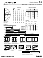
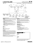
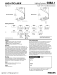
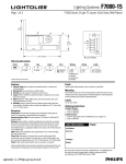
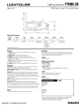
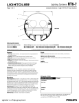
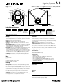
Lighting Systems
1BHFPG
A-3
"MFSPOÜ4FSJFT-JHIU51FShDN
4FDUJPO
7
2
4
1
3
9-9/16”
(24.29cm)
6
3-5/8” (9.21cm)
12-3/8” (31.43cm)
NOT TO SCALE
Module Ordering Information
Family
A
Series
Track
1
Length
Shielding
B
A = Track
B = No Track
Lamps
Finish
Options
B
4 = 4-Foot
8 = 8-Foot
12 = 12-Foot
A = No Shield
B = Solid Shield
C = Perf Shield
D = Lens Shield
28 = 28w
54 = 54w
WH = White
AL = Aluminum
Complete ordering instructions below.
E1 = Emergency Pack, 120v
E2 = Emergency Pack, 277v
D1 = Dimming 120v
D2 = Dimming 277v
X5 = 5 Through Wires
Features
Electrical
1. Housing: Extruded aluminum housing in lengths of 4’ (121.92cm), 8’ (243.84cm)
and 12’ (365.76cm). There are no exposed fasteners. The end caps are die-cast
aluminum sculpted and finished to match the housing.
2. Lens: Extruded clear acrylic linear prismatic lens.
3. Reflector: Die-formed high purity anodized specular aluminum.
4. Lamping: One T5 28W or 54W lamp per four-foot nominal length. Provided
by others.
5. Alignment Mechanism: The housing and the end cap each have a draw tight
mechanism that creates a hairline joint along and at the ends of the run. To
operate the mechanism, the installer tightens two screws.
6. Track Option: The housing has the capability of having single circuit Lytespan®
track fixtures for accent lighting. The track is an integral component of the
housing. The fixture housing comes with a cover to conceal any portion of the
track that doesn’t have a track fixture installed. The cover can be cut to length
in the field. There is an optional cover (ATC) that creates a nearly seamless
transition from the fluorescent fixture to the track fixture.
7. Shielding: Die-formed 0.060” (0.15cm) aluminum finished high reflectance
white.
Ballast is <10% THD, 1.0 ballast factor, program start. Color-coded quick
connectors allow ease of connection for joiner modules. For special circuiting
consult factory. Factory installed ballast disconnect allows the ballast to be
disconnected from and reconnected to incoming power under load without turning
the entire circtuit off.
Dimming: 120/277 VAC 1% dimming level, 4 or 5 wire feed required.
Emergency Battery Pack: 28 watt: 520 lumens @ 90 minutes, 54 watt: 700
lumens @ 90 minutes.
There are two types of power feed end sets for the track option. One has a stem
containing five solid wires and the other end set has one 5 wire and one 3 wire
stem. Single power feed end sets allow for 16 amps of track fixtures per run while
dual power feed end sets allow 32 amps per run.
Labels
UL, cUL and I.B.E.W.
Finish
Powder coated baked white or silver enamel.
Custom colors available, consult factory.
Mountings
All mounting is on 48” (121.92cm), 96” (243.84cm) and 144” (365.76cm) centers.
Cable Suspension (not shown) 4 1/2" (11.43cm) diameter flat canopy finished
white enamel, 1/16" (0.16cm) diameter stainless steel aircraft cable adjustable up
to 36" (91.44cm) and adjustable cable gripper. Cable mounting at the ends of a run
is not available when track is being used. Installing stems at the ends of the run
will prevent the fixture from hanging off center caused by the weight of the track
fixture. Cable suspension can be used in the center of runs that have track
installed. Consult factory for other options.
Stem Mounting (not shown) - 4 1/2" (11.43cm) diameter flat canopy, 1/4"
(0.64cm) IP (1/2” (1.27cm) OD) stem. The stem can accommodate up to 2-12 gauge
and 3-18 gauge solid wires. All components have a white finish.
Ordering Instructions
Individual Fixtures:
1. Order number of MODULES required.
2. Order one POWER FEED END SET per MODULE.
Continuous Rows:
1. Determine run length.
2. Order the appropriate number of MODULES for the complete run.
3. Order one POWER FEED END SET per run.
4. Order one INTERMEDIATE SUSPENSION per MODULE minus one per run.
5. For runs that exceed amperage limits, order the appropriate number of
INTERMEDIATE POWER FEEDS.
Job Information
Type:
Job Name:
Cat. No.:
Lamp(s):
Notes:
"JSQPSU3PBE'BMM3JWFS."t
t'BY
We reserve the right to change details of design, materials and finish.
XXXMJHIUPMJFSDPN½1IJMJQT(SPVQt $
Lighting Systems
1BHFPG
"MFSPOÜ4FSJFT-JHIU51FShDN
4FDUJPO
Performance
160
170
180
150
80
90
100
110
120
130
140
70
125
50
60
250
375
40
30
0
10
20
REPORT NO: ITL50916
CAT NO: AIX4B54
LAMPS: 1-F54T5
LUMENS: 5000
EFFICIENCY: 55.7%
ZONE
DEG.
0
180
175
165
155
145
135
125
115
105
95
90
85
75
65
55
45
35
25
15
5
0
0
1
3
16
58
102
129
120
67
17
7
71
158
226
298
361
414
456
482
497
498
CANDLEPOWER
22
45
CANDELAS
0
0
1
1
2
2
8
5
33
14
62
32
78
34
64
272
109
268
112
202
107
181
124
173
192
215
245
300
301
346
363
366
418
407
461
451
486
484
498
496
498
498
67
90
0
1
2
3
2
4
228
385
332
246
204
195
247
341
391
404
413
449
484
496
498
0
0
2
2
1
5
370
409
344
252
224
208
252
340
398
414
413
445
480
496
498
COEFFICIENTS OF UTILIZATION
% EFFECTIVE CEILING CAVITY REFLECTANCE
80
70
50
WALL REFLECTANCE
0
1
2
3
4
5
6
7
8
9
10
ROOM CAVITY RATIO
CANDLEPOWER CURVE
500
70
62
55
50
45
41
37
3
32
29
27
26
50
62
52
45
39
34
30
27
24
22
20
18
30
62
49
40
34
29
25
22
19
17
15
14
70
59
52
47
42
38
35
32
30
28
26
24
50
59
49
42
37
32
28
25
23
21
19
17
30
59
47
38
32
27
24
21
18
16
15
13
50
53
44
37
32
29
25
23
21
19
17
16
30
53
42
34
29
25
21
19
17
15
13
12
10
53
40
32
26
22
18
16
14
12
11
10
20% FLOOR CAVITY REFLECTANCE
DISTRIBUTION
Zone
Lumens
0-90
1948
90-180
837
0-180
2785
% Lamp
39.0
16.7
55.7
% Luminaire
70.0
30.0
100.0
4' (121.92cm) 8' (243.84cm) 12' (365.76cm)
End Set Suspension
Module
Module
Module
4' (121.92cm) Run
1
1
8' (243.84cm) Run
1
1
12' (365.76cm) Run
1
1
16' (487.68cm) Run
2
1
1
20' (609.60cm) Run
1
1
1
1
24' (731.52cm) Run
2
1
1
Fixture Lengths and Mounting Locations
48” (121.92cm)
4-Foot
4’ 7” (139.87cm)
96” (243.84cm)
8-Foot
8’ 7” (261.62cm)
144” (365.76cm)
12-Foot
12’ 7” (383.54cm)
96” (243.84cm)
144” (365.76cm)
20-Foot
20’ 7” (627.38cm)
Mounting Accessories
A1TES24ALD = Aluminum
A1TES24WHD = White
Dual Power Feed End Set
5 Wires (2-12 ga., 3-18ga.) on One End
3 Wires (2-12 ga. 1-18ga.) on One End
24" (60.96cm) Stems for Track
A1TES24ALS = Aluminum
A1TES24WHS = White
Single Power Feed End Set
5 Wires (2-12 ga., 3-18ga.) on One End
24" (60.96cm) Stems for Track
12" (30.48cm)
7"
(17.78cm)
6"
(15.24cm)
7" (17.78cm)
ALS24
Intermediate
24" (60.96cm) White Stem Set
6"
(15.24cm)
6"
(15.24cm)
A1LAL= Aluminum
A1LWH = White
"L" Joiner Block
A-3
AC36
Intermediate
36" (91.44cm) Cable Set
ACC36X4
Intermediate 36" (91.44cm)
Cable & 4 Wire 18 ga.
Cord Set for Fluorescent Only
12"
(30.48cm)
7"
(17.78cm)
4-7/16"
(11.27cm)
12" (30.48cm)
12" (30.48cm)
A1TAL = Aluminum
A1TWH = White
"T" Joiner Block
A1XAL = Aluminum
A1XWH = White
"X" Joiner Block
A1ILAL = Aluminum
A1ILWH = White
Inline Joiner Block
Job Information
ATCAL = Aluminum
ATCWH = White
Track Adapter
Type:
"JSQPSU3PBE'BMM3JWFS."t
t'BY
We reserve the right to change details of design, materials and finish.
XXXMJHIUPMJFSDPN½1IJMJQT(SPVQt $