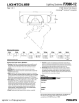
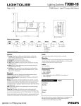
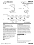
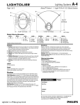
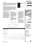
1
Lighting Systems
1BHFPG
F7000-26
'4FSJFT-JHIU5-FOT8BMM.PVOU
3.25”
(8.26cm)
4
5
1.63”
(4.14cm)
6
1
4.51” (11.46cm)
Ordering Information
Family
FW7
Series
6
6 = Lens
Type
5
5 = Extruded
Lens
Lamps
Color
Wattage
Voltage
Length
1
1 = 1 Lamp
AL = Aluminum
WH = White
Complete Ordering Instructions below.
1 = 28W
2 = 54W
3 = 28W Dimming
4 = 28W EM
5 = 54W Dimming
6 = 54W EM
1 = 120v
2 = 277v
4 = 4’ (121.92cm)
8 = 8’ (243.84cm)
Features
Mounting
1. Housing: Single piece of high purity extruded aluminum, a portion from
recycled material.
2. Housing End: Die-cast aluminum, welded in place.
3. End Cap: Die-cast aluminum. Encloses the end of the run.
4. Lamps: F28T5 or F54T5HO as specified. By others. Installed from the
ceiling side of the luminaire.
5. Ballast: Electronic. Meets ANSI starting, end-of-life protection and sound
rating specifications. Low THD.
6. Shielding: Extruded acrylic with suspended bead texture; inset metal rod.
Each module includes two wall-mounting brackets. Bracket hole pattern accommodates junction box (single gang box rotated 90 degrees) or other appropriate
mounting method using customer supplied fasteners.
Electrical
Connections: Pre-wired with 18 gauge wires and polarized cannon plug connectors for simultaneous mechanical/electrical connection.
Emergency Battery Pack: 90 minute operation, 700 lumens for 54W and 520
lumens for 28W.
Dimming: Advance Mark X standard (no additional wires required); use compatible dimmer. Dimming ballasts using additional control wires (eg Lutron Hi-Lume
or ECO-10, Osram) can be used; consult factory and use X4 or X5 power feeds
with additional leads, as appropriate. Ballast not to exceed 1.25” (3.18cm) wide by
1.20” (3.05cm) high.
iGEN: F7000 accepts iGEN (DALI) with supplemental 2-wire control technology.
Use with X5 power feed.
Power Tray: Code-gauge, die-formed steel, pre-paint white enamel finish;
secured by quarter-turn fasteners for easy access to wiring. Holds ballasts, sockets, and wiring. Accepts ballasts up to 1.25” (3.18cm) wide by 1.20” (3.05cm) high.
Labels
UL, cUL and I.B.E.W.
Ordering Instructions
Individual Fixtures:
1. Order one MODULE.
2. Order one END SET.
Continuous Rows:
1. Order the appropriate number of MODULES for the complete run.
2. Order one END SET.
Finish
Powder coated White or Aluminum baked enamel.
Custom colors are available, consult factory.
Labels
UL , cUL and I.B.E.W.
Job Information
Type:
Job Name:
Cat. No.:
Factory installed ballast disconnect allows the ballast to be disconnected from and
reconnected to incoming power under load without turning the entire circuit off.
Finish
Lamp(s):
Powder-coated, baked enamel, white or aluminum, as specified.
Notes:
"JSQPSU3PBE'BMM3JWFS."t
t'BY
We reserve the right to change details of design, materials and finish.
XXXMJHIUPMJFSDPN½1IJMJQT(SPVQt E0808
Lighting Systems
1BHFPG
'4FSJFT-JHIU5-FOT8BMM.PVOU
Performance
ZONE
DEG.
0
170
180
100
90
80
70
60
500
50
40
30
0
10
20
REPORT NO.: ITL54696.IES
LAMPS: 1-F54T5
LUMENS: 5000 each
EFFICIENCY: 81.6%
CAT. NO.: F7762WH214
45
67
90
510
516
508
479
435
378
307
228
142
62
42
104
341
504
650
774
870
928
957
959
950
510
510
492
455
405
340
264
181
92
18
0
38
186
351
506
646
767
860
921
952
950
80%
CANDELAS
130
120
110
0
5
15
25
35
45
55
65
75
85
90
95
105
115
125
135
145
155
165
175
180
22
510
519
523
508
477
431
375
304
223
151
132
164
378
656
894
988
1048
1056
1033
972
950
510
519
523
505
474
427
367
296
216
141
120
153
383
652
874
960
1022
1039
1020
967
950
510
520
519
497
458
406
341
267
185
106
85
129
366
624
775
887
957
999
996
967
950
ROOM CAVITY RATIO
160
150
140
250
1000
COEFFICIENTS OF UTILIZATION
% EFFECTIVE CEILING CAVITY REFLECTANCE
CANDLEPOWER
CANDLEPOWER CURVE
750
F7000-26
50
83
72
63
55
48
43
39
35
31
29
26
0
1
2
3
4
5
6
7
8
9
10
30
83
70
58
49
43
37
32
28
26
23
20
70%
WALL REFLECTANCE
50 30 10
76 76 76
65 63 60
57 53 49
50 45 41
44 38 34
39 33 30
35 30 26
31 26 22
29 23 20
26 20 17
24 19 15
10
83
66
54
45
37
32
27
24
21
19
16
50%
50
60
52
45
40
35
31
28
26
23
21
20
30
60
50
43
36
31
27
24
21
19
17
15
10
60
48
40
33
28
24
20
18
16
14
13
20% FLOOR CAVITY REFLECTANCE
DISTRIBUTION
Zone
Lumens
0 - 90
1279
90 - 180
2790
0 - 180
4069
% Lamp
25.5
56.1
81.6
%Luminaire
31.0
69.0
100.0
Fixture Lengths & Mounting Reflected (Plan View)
2'-8"
(81.28cm)
6'-8" (203.20cm)
16.00" (40.64cm)
4'-3" (129.54cm)
8'-3" (251.46cm)
6'-8" (203.20cm)
1'-4"
(40.64cm)
2'-8"
(81.28cm)
3/4"
(1.91cm)
JOINING DETAIL
GAP BETWEEN FIXTURES
12'-3" (373.38cm)
6'-8" (203.20cm)
1'-4"
(40.64cm)
6'-8" (203.20cm)
16'-3" (495.30cm)
1-1/2"
(3.81cm)
6'-8" (203.20cm)
1'-4"
(40.64cm)
6'-8" (203.20cm)
1'-4"
(40.64cm)
2'-8"
(81.28cm)
20'-3" (617.22cm)
3/8" (0.95cm)
END OF ROW DETAIL
Recommended mounting is a single gang outlet box rotated 90 degrees at the
feed point. Remaining mounting points could be outlet boxes as well, or a couple
of holes per mounting point spaced 3-1/4” (8.26cm) at 1-3/4” (4.45cm) above the
bottom of fixture.
Mounting Accessories
Wall Mount End Set
FW7EWH = White
FW7EAL = Aluminum
Job Information
Type:
"JSQPSU3PBE'BMM3JWFS."t
t'BY
We reserve the right to change details of design, materials and finish.
XXXMJHIUPMJFSDPN½1IJMJQT(SPVQt E0808