1
—-
I
INSTRUCTION
SUSPENSION BEAM
FOR USE WITH BASIC OR ADVENT LYTESPAN@ TRACK SYSTEMS ONLY
SHEET NO.
IS:6440
Page 1 of 4
R0790
READ AND UNDERSTAND THESE INSTRUCTIONS BEFORE PROCEEDING.
This fixture is intended for installation
in accordance
with the National
Electrical
Code and local regulations.
TO assure
full
compliance
with local codes and regulations,
check with your local electrical
inspector
before installation.
To prevent electrical
shock, turn off electricity
at fuse box before proceeding.
Retain these instructions for maintenance rafaranca.
Suspension
Beam is a system of extruded aluminum
housings which enclose Basic Lytespan (1 circuit) or Advent Lytespan (2 circuit)
Track. The housings
may be used individually,
in continuous
runs or in a variety of patterns. They may be suspended
on cables or
stems. They may also be mounted wall to wall without ceiling supports
in spans up to 12’.
The housings
housing/splice
may be cut, but must be straight and square. The cut end of a housing may be attached
box. Power cannot be fed into the cut end of a housing from a cable or stem kit.
to another
housing
or to a
CAUTION:
● TURN OFF POWER AT FUSE BOX BEFORE INSTALLING TRACK.
Q INSTRUCTIONS FOR GROUNDING PER INSTRUCTION SHEET OF THE FEED-IN KIT MUST BE FOLLOWED.
FAIIAJRE lU DO SO MAY RESULT IN A HAZARDOUS CONDITION.
● DO NOT SUPPLY ADVENT TRACK FROM TWO SEPARATE 120V BRANCH CiRCU#TS AS THIS COULD
OVERLOAD THE NEUTRAL TRACK CONDUCTOR LEADING TO AN ELECTRICAL SAFETY HAZARD.
● OBSERVE POLARITY, WHITE SUPPLY LEAD (NEUTRAL) lQ
CONTACT ON B@ADSIDE OF TRACK.
● REFER TO LOAD DATA, PAGE 4, FOR MAXIMUM
SUSPENSION BEAM LOADING.
INSTALLATION
OF SUSPENSION
Power may be fed from
housing/splice
box.
MOUNTING
cables
or stems
BEAM WITH CABLE OR STEM KITS
through
either
end of straight
run of housings,
including
the end of a housing
attached
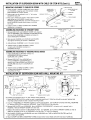
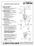
CABLE KITS TO CEILING
4’ OCTAGONAL
Lay out cables so they will be uniformly
spaced along housings;
do not exceed 8’ spacing. In an open pattern locate first and
iast cables approximately
1’ from the ends.
Cables are NOT
RECOMMENOEO for straight runs.
Locate cabie with electrical
feed no closer than 6“ and no
further than 10” from the end of housing to which power is to be
fed. The 10” distance permits the supply leads to reach the
wiring compartment
and may be increased
by the amount the
cable kit is shortened
on the job.
1. To shorten
cables,
diagonal cutters)
excess cable.
crimp
LOOSE CABLE
at desired
2. Fasten TRACK CLAMPS
washer and nut.
position
GROUNO
_
SCREW
TOGGLE
~
(with
?
MOUNTING
~
1
LEADS
~
s~ SCREW
UPPERCOLLAR
cAeLE
with
ADJUSTING
b. CABLE KiT fasten MOUNTiNG
with TOGGLE BOLT.
PLATE
~
~
:.,’
WIRE
eOLT
SUPPLY
&
and cut off
to SPECIAL
3. a. CABLE KiT WITH ELECTRICAL
Splice SUPPLY LEADS to branch
outlet box (white to white, black
for Advent) and fasten GROUND
Cap or cut red lead when using
MOUNTING PLATE to outlet box
box screws.
4. Screw UPPER COLLAR
tighten set screw
CLAMP
.. . . . . .
OUTLET
eox (ey others)
FEED:
circuit leads in
to black, red to red
WIRE to outlet box.
Basic Track, Fasten
with outlet
yy
~
COLLAR
~.
‘pEC’AL ‘CRW”
PLATE to ceiling
to MOUNTiNG
e
PLATE and
Cablo Klt
With
Rlootrical hod
Cabio Kit
FIG. 1
,j:.T.
,. ~:,
MOUNTING STEM KITS TO CEILING
Lay out stems so they will be uniformly spaced along housings; do not exceed 8’ spacing.
in a straight run or an open
pattern locate first and last stems approximately
1‘ from the ends. Locate stem for power feed at ieast 6“ from the
end of the housing to which power is to be fed.
See Instruction Sheet packed with STEM KIT for instructions
on shortening stems, mounting
stems to ceiling and installing the STEM EXTENSION KIT. Make sure supply leads (not supplied)
from stem are long enough to reach the feed-in point to the track.
?
!!
‘1
J
STEM KIT
1-
I
<51-1709-1
Is
1?”
:Y:::::L,N::::::,E:i::::
to a
-
INSTALLATION
MOUNTING
OF SUSPENSION
HOUSINGS
1S:6440
BEAM WITH CABLE OR STEM KITS (Cent’d.)
,
TO CABLES OR STEMS
Paae 2 of
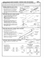
CABLE(ORSTEM)
AR
1. Loosen screws in TRACK CLAMPS and insert clamps
into HOUSING, engaging
upper ribs between
Slide HOUSING to position desired.
2. Cable length may be adjusted
ADJUSTING COLLAR.
up to ‘A”
by
clamps.
..
WIREWAY
turning
3. Pass supply leads (from cable or stem used for power
feed) along top of HOUSING, through hole in
WI REWAY COVER BRACKET and down through slot in
end of HOUSING through which power is to be fed
into track.
4. Tighten screws in TRACK
installation
is completed.
ASSEMBLING
CLAMPS
HOUSINGS
after
SLO
~v
HOUSING
IN STRAIGHT
,-~
..,...,.
.-.
‘ (-’’”
‘>
FIG. 2
SUPPLYLEADS
RUNS
“’m.:””
!-. -.-, “,
1. Remove END PLATE and WI REWAY COVER from adjacent
ends of HOUSINGS. Insert COUPLER and SPLINES halfway
into one of the HOUSINGS and tighten set screws to
secure COUPLER to HOUSING.
--Q.
/
cOuqRT
SET SCREW
2. Slide second HOUSING onto COUPLER and SPLINES
and tighten remaining
set screws in COUPLER.
1
91
3. Add additional
HOUSINGS
to run in the same manner.
4. Tighten screws in TRACK CLAMPS
or stems after HOUSING installation
completed,
see Fig.2
ASSEMBLING
HOUSINGS
“2ss’L’NE&
of cables
is
HOUSING
END PLATE
TO HOUSING/SPLICE
SCREW
FIG. 3
BOXES
into
COUPLER-
2. Remove END PLATE from HOUSING and
re-mount WI REWAY COVER BRACKET to
second hole. Slide HOUSING onto COUPLER
and SPLINES and secure to COUPLER with
CLAMP.
INSTALLATION
_A-.
(discard)
1. Insert COUPLERS and SPLINES halfway
HOUSINGK3PLICE
BOX and secure
COUPLERS with CLAMPS.
3. Tighten screws in TRACK CLAMPS
or stems after HOUSING installation
completed,
see Fig. 2.
J,
Q
HOUSINGISPLICE
—.
,,
,.
A
of cables
is
OF SUSPENSION
7
CLAMP —N~%v’
—
BOX
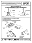
BEAM WITH WALL MOUNTING
KIT
MOUNTING
(L
(not furnished)
‘w
/’”-
PLATE
CUMP
-
\d
“RE’’’:VER
=IU:IEI
I“’=;;”
a
.\
.,’1
T
(
,~”,.. ‘
\b +
,+
...
*.
HOUSING
/
v
%
k
For straight
END PLATE (di~~~~rj)
runs. SuppOrtS
FIG. 5
L
up to 12’ span without
BRANCH
ceiling
CIRCUIT
LEADS
supports.
1. Fasten MOUNTING PLATES to outlet box and to opposite
parallel
mounting
surface should be solid to accept mounting
screws.
2. In a run of HOUSINGS,
KIT (discard COUPLER
join HOUSING
furnished
with
4. Measure the distance between the MOUNTING
length (or the length of the run of HOUSINGS)
6. Mount
CANOPY
COVERS
wall.
Outlet
box should
be securely
together as previously described.
Use COUPLER furnished
HOUSING).
Install COUPLER with flat side down.
3. Remove END PLATES from HOUSING(S).
Mount WI REWAY
HOUSING.
Remove WI REWAY COVER from other end.
5. Slip CANOPY COVERS onto
Lock in place with CLAMPS.
FIG. 6
HOUSING(S)
to MOUNTING
COVER
BRACKET,
at feed-in
PLATES. Cut HOUSING, at end without
is not less than 3/16” than this distance.
and twist
PLATES
HOUSING(S)
and pull branch
leads (solid
with WALL
end, to second
WI REWAY
onto TABS on MOUNTING
circuit
fastened
MOUNTING
hole in
COVER,
PLATES,
and
so that
see Fig. 6.
wire only) out of outlet
box.
..its
INSTALLATION
OF BASIC OR ADVENT
Each straiaht
run of track
To cut track,
see Instruction
is started
Sheets
LYTESPAN
with an lNDIVi DUAL TRACK
supplied
1S:6440
TRACK INTO HOUSINGS
UNIT and continued
with JOINER
Paae
------3 of z
TRACK
UNITS.
with Track. 1S:6020 or 1S:6121.
I
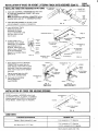
ALLEN
ASSEMBLE
1.
Prepare
MOUNTING
MOUNTING
CLIPS TO TRACK
CLIP ASSEMBLIES
7/8”
HEAD SCREW
Long for Basic Track,
1[2’( Long for Advent
as shown.
—CAPTIVE
2. Remove DEAD END COVER from INDIVIDUAL
TRACK UNITS, see Fig. 8. Insert MOUNTING
CLIPS into end of each track unit and slide
along track until ends of clips engage alignment
holes. Check that allen head screw lines up with
hole in track.
INSTALLING
B
Track
NUT
SPACER.Useonly
N
for Basic Track
CH
MOUNTINGCLIP
MOUNTINGCLIP
ASSEMBLY
FIG. 7
TRACK INTO A SINGLE HOUSING
HOUSING
1. Unscrew BOTTOM COVER and remove KO from
top plate on LIVE END. Reinsert DEAD END
COVER into other end of track.
NOTE: See Instruction
Sheet supplied with track
for additional
instructions
on installing
supply
leads into LIVE END.
WALL
MOUNTING
KIT
INDIVIDUAL
TRACK
UNIT (Basic)
2. Pass supply leads through openings
in LIVE
END observing
polarity. Insert track into
HOUSING and tighten screws in MOUNTING
CLIPS with allen wrench to lock track in place.
1.
MOUNTING
...
~ALLEN
CLIP ASSEMBLY
WRENCH
-
‘
CAPTIVE
NUT
3. Fasten BOTTOM COVER to LIVE END. Connect
SUPPLY LEADS to screw terminals
as shown in
track IS:6020 or IS:6121.
BOTTOM
INSTALLING
TRACK INTO A STRAIGHT
1. Follow previous instructions
except
reinstall
DEAD END COVER.
TRACK INTO HOUSINGS
LIVE ENDS from all INDIVIDUAL
ENDPLATE
c1
Q’
~
INDIVIDUALTRACK
UNIT(Bas[c)
‘~jjf%ij~;jR
Track UnN)
.:::$J
JOINERTRACK
UNIT(Basic)
~
@-
A
MOUNTINGCLIP
/“
-“3
,//
1
{
..’
..’
,.-
HOUSING
~COUPLER
Remove
UNITS.
,.
do not
3. Tighten screw in COUPLER(S). Insert DEAD E?JD
COVER into end of track run and insert END
PLATE into end of HOUSING.
1.
,/ /-
RUN OF HOUSINGS
Insert
2. Remove END PLATE from HOUSING.
JOINER TRACK into HOUSING, plug COUPLER
into INDIVIDUAL
TRACK UNIT and tighten
screws in MOUNTING CLIPS with allen wrench,
Repeat for all JOINER TRACK UNITS in run.
INSTALLING
COVER
~
ASSEMBLY
#/&;:H
FIG. 10
SCREW
*
IN PATTERNS
TRACK
.k
LIVE END x
(discard)
e
INDIVIDUAL
-.
-
-
‘=’
..-
SCREW
---
:>-\-
c
FIG. 11
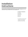
TO REMOVE
2. Lay out the track
per the layout ot tne
HOUSINGS following
the track orientation
shown in Fig. 12. Note
that each straight run
of track consists
of an INDIVIDUAL
Plus JOINERS.
TRACK
UNIT (Basic)
.
.
LOOSEN
r
TRACK ORIENTATION
“T” Intersection
Corner
An
M.
R[ght of
Track = R
Left of
Track = L
‘f:~
““’f’i~;:f’s”
“X”
‘“;
R
5
~j
~~
FIG. 12
L]R+
Intersection
1S:6440
OF BASIC OR ADVENT
INSTALLATION
INSTALLING TRACK INTO HOU!jlNGs
LYTESPAN
IN pATTERNs
TRACK INTO HOUSINGS
(Cent’d.)
AUX.ELECTRICAL
CONNECTOR
POLARITYKEY
r
/
into track units
3. Insert AUX. ELECTRICAL CONNECTORS
at corners and intersections,
POIARITY
KEY points
away from BEAD.
NOTE One extra AUX. ELECTRICAL CONNECTOR will be
discarded when used with “T” HOUSING/SPLICEBOX.
Page 4 of i
TRACK
4~G”\
.C .
#
.,\
“/”
&
(Basic)
DEAD
‘h~
‘%
C%R
Y
BEAD ~
‘*&[
4. Insert DEAD END COVERS into the end of track
units not adjacent to corners or intersections.
e,,
FIG. 13
TRACK
5. Insert INDIVIDUAL
UNITS into appropriate
HOUSINGS and tighten
screws in MOUNTING CLIPS
with allen wrench to lock
track in place.
HOUSING
HOUSINGK5PLICE
BOX
~
,/
&
,.-
\
.
,/
CAPTIVE
NUT
AIJx
SPACER
,
ELEc~Rlf.AL~
.-
FIG. 14
*
+
~
‘,~D,v,~uAL TRAcK
MOUNTING
CLIP
UNIT
ASSEMBLY
~ATLEN’wRENcH
CONNECTOR
HOUSING
L
~
HousNG<4-HOus’~~~pL’cE
TRACK
~
(Saslc)
AUX. ELECTRICAL
CONNECTOR
L—
~
ALLEN
JOINER
wRENCH
MOUNTING
TRACK
UNIT
CLIP
FIG. 15
INDIVIDUAL
TRACK
ALLEN WRENCH
FIG. 16
UNIT (Basic)
COUPLER
Splice leads from AUX. ELECTRICAL
CONNECTORS
to supply leads (for
power feed) or to each other (for power
continuity).
Follow color code white to
white, black to black and for ADVENT,
red to red.
>
HOUSINGK$P
BOX
s
—-
L
AL
Cap any unused leads from AUX.
ELECTRICAL CON NECTOR(S).
HOUSINGISPLICE
—1
BOX
Push leads into HOUSINGI
SPLICE BOXES and
insert COVERS.
CO=%
COVER%
FIG. 17
POWER FEED
INSTALLATION
.
-..>
,/ “
““
6. In each straight run of
HOUSINGS, insert JOINER
TRACK UNIT into HOUSING,
plug COUPLER into individual
TRACK UNIT and
tighten screws in MOUNTING
CLIPS and COUPLERS.
Repeat for all JOINER TRACK
UNITS in run.
,/
‘.
OF COVER FOR HOUSING
COVER is installed
in HOUSINGS without track.
Cut COVER if required.
In patterns, cut COVER to
distance between the COVERS for the HOUSING/
SPLICE BOXES. COVER snaps into HOUSING.
FIG. 18
POWER CONTINUITY
OPENING
HOUSINGESPLICE
BOX
/
HOUSING
~
&
,
u
.
*C’
;
COVER
,,
L
COVER
--1’
FOR HOUSING
OPENING
(
FIG. 19
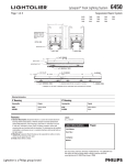
LOAD DATA
4
MAXIMUM
SUSPENSION BEAM MOUNTING
Cables
Wall
or Stems,
Mounting
spaced
8 Ft. apart
Kit, 12 Ft. Span
LOAD
5 lb. Lytespots
on 1 Ft. Spacing
5 lb. Lytespots
on 3 Ft. Spacing
or 3.5 lb, Lytespots
Most
Lytespots
on 2 Ft. Spacing
weigh
under 3 Ibs.