1
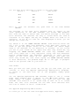
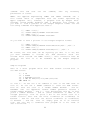
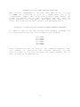
FEDERAL COMMUNICATIONS COMMISSION
RADIO FREQUENCY INTERFERENCE STATEMENT
Warning: This equipment has been certified to comply with the
limits for a class B computing device, pursuant to Subpart J of
Part 15 of the FCC Rules.
RamWorks D.P. RCB option FCC ID: EYW5QGAERGBOPT INSTRUCTIONS TO THE USER
This equipment generates and uses radio frequency energy and if
not installed and used properly, i.e., in strict accordance with
the operating instructions, may cause interference to radio or
television reception. It has been tested and found to comply
with the limits for a class B computing device pursuant to
Subpart J of Part 15 of the FCC Rules, which are designed to
provide
reasonable
protecton
against
such
interference
when
operated in a residential installation.
If this equipment does cause interference to radio or television
reception, which can be determined by turning the equipment on
and
off,
the
user
is
encouraged
to
try
to
correct
the
interference by one or more of the following measures:
*
Reorient the receiving antenna.
*
Relocate the equipment with respect to the recerver.
*
Move the equipment away from the receiver.
*
Plug the equipment into a different outlet, so that the
equipment and receiver are on a different branch circuit.
If necessary,
suggestions.
consult
your
service
representative
for
additional
The
manufacturer
is
not
responsible
for
any
radio
or
TV
interference
caused
by
unauthorized
modifications
to
this
equipment. It is the responsibility of the user to correct such
interference.
IMPORTANT INFORMATION ABOUT CABLES AND CONNECTORS
This
product
was
FCC
certified
under
test
conditions
that
included use of shielded cables and connectors between system
components. A shielded cable is one that uses a metallic wrap
around
the
wires
to
reduce
the
potential
effects
of
radio
frequency interference. It is important that you use shielded
cables/connectors
to
reduce
the
possibility
of
causing
interference to radio, television, or other electronic devices.
1
TABLE OF CONTENTS
CHOOSING AN RGB MONITOR
4
INSTALLATION OF THE RGB EXTENDER
5
USING THE RGB EXTENDER
7
Text Color Switches and Color Mapping Switch
7
Text Modes
8
The Applied Engineering RGB Software
8
Sample Programs
11
AN RGB TUTORIAL
12
What is RGB ?
12
Double Hi—Res On the Apple IIe
13
APPENDIX A:
RGB Routine Locations
15
APPENDIX B:
Using the RGB Extender from Assembly Language
15
APPENDIX C:
RGB Connector Pin Outs
16
TROUBLE SHOOTING GUIDE
17
2
Welcome to a new world of exciting RGB color!
Applied Engineering RGB Extender Card Features
*
100 % compatible
text modes
*
Four color switch selectable color text (blue, white, amber,
or green) in either 40 or 80 column mode
*
True RGB reproduction of Apple IIe double density modes
*
Works with
monitors.
BOTH
with
Apple
Apple
IIe
compatible
hardware
AND
for
IBM
graphics
compatible
and
RGB
NOTICE:
THE ROB CARD DESIGN AND PCB LAYOUT WERE BOTH COPYRIGHTED
BY
APPLIED
ENGINEERING.
THIS
MANUAL
IS
ALSO
COPYRIGHTED,
APPLIED ENGINEERING AUTHORIZES OWNERS OF THE RGB CARD TO
LIMITED NUMBER OF COPIES FOR THEIR OWN USE.
3
IN 1984
HOWEVER
MAKE A
CHOOSING AN RGB MONITOR
One of the features of the Applied Engineering RGB Digital Prisim
(tm) is its ability to be used with both Apple compatible RGB
monitors and IBM compatible RGB monitors. To facilitate use with
both
types
of
monitors,
the
Digital
Prism
includes
two
connectors along the back edge.
One connector is the 16 pin connector found along the lower part
of the back edge and is the exact same connector as the one on
the original Applied Engineering RGB Option for the Ramworks (tm)
card. This connector is used for Apple compatible RGB monitors,
and is connected via a ribbon cable to a 15 pin D—type connector
which plugs directly into the cable of an Apple compatible RGB
monitor.
The second connector, which is new on the Digital Prisim and was
not included on the original Ramworks RGB option, is found along
the upper part of the back edge of the card and has l0 pins. This
connector is meant to be used with IBM compatible monitors and is
connected via a ribbon cable to a 9 pin D—type connector which
will plug directly into the cable of an IBM compatible RGB
monitor.
4
INSTALLING THE RGB EXTENDER ON THE RAMWORKS CARD
****************************************************************
*
*
*
NOTE: Never attempt to remove or insert cards
*
*
in any slot of the Apple IIe while the
*
*
power is turned on. Doing so could cause
*
*
damage to both the Apple motherboard and
*
*
the card.
*
*
*
****************************************************************
1)
Turn the power to the Apple IIe OFF.
2)
Remove the Ramworks card from the auxillary slot.
3)
The Applied Engineering RGB Digital Prisim is provided
with cables that will allow you to use it with both IBM
compatible RGB monitors and Apple compatible RGB monitors.
Remove the cable which will NOT be used with your monitor and
save
it
along
with
its
mounting
hardware
in
a
safe
location.
4)
Plug the RGB extender into its connectors on the Ramworks
card. Notice that on the Ramworks card there are two sets
of connectors, one set on the chip side of the card and
one set on the solder side of the card. The set of
connectors on the solder side is the one designed for the
RGB extender. (The connectors on the chip side are for
the Ramworks 512K or 2 Meg piggyback cards and are NOT
compatible with the RGB card.) Line the RGB extender and
the Ramworks up so that the the chip sides of each card
face in the same direction. Line the connectors up so
that all pins on the RGB card will slide into a slot on
the Ramworks card and gently push the two together until
they are mated and will not go any further.
5)
While the power to the Apple IIe is still OFF, gently push
the Ramworks card back into the auxilary slot on the Apple
IIe motherboard.
6)
Route the video cable out of one of the holes in the back
panel of the Apple IIe’s case. Use the mounting hardware,
which consists of a flange and two screws, to mount the
connector to the Apple’s back panel. Connect the cable to
the cable coming from the RGB monitor. See diagram on page
five for more information.
7)
Insert the ProDOS disk supplied by Applied Engineering
into the boot drive. Now turn on the power and enjoy a
5
Hex
Stand-off
Apple IIe
Rear Panel
Connector
Nut
Mounting
Plate
Cable
CONNECTOR DETAIL
Panel Connector
RGB Signal
Cabler
RGB Card
RGB Card
Apple IIe
power supply
Ramworks Card
Ramworks Card
6
USING THE APPLIED ENGINEERING RGB EXTENDER
When you have completed the installation of the RGB extender and
turned on the power to the RGB monitor and the Apple, with the
Applied Engineering boot disk (which is a ProDOS disk named /RGB)
in the boot drive, you will first see the ProDOS startup message,
then you will see the Applied Engineering startup message. If
this is not what you see, then turn off the power and check to
see that the card is properly installed and all of the cables are
properly connected.
If you are using a monitor that requires the ribbon cable with
the 9 pin D—type connector, and if the picture is rolling and not
getting proper sync, then you will want to try changing the SYNC
SELECTION SWITCH, which is one of the dip switches located on the
end of the Digital Prisim card which is closest to the keyboard
of the Apple lie when the Digital Prisim and Ramworks are
correctly installed in the computer. There are four dip switches
mounted
in
a
red
rectangular
plastic
enclosure.
The
Sync
Selection Switch is switch 3 of the dip switches. When the Sync
Selection Switch is pushed so that it is down toward the side
marked OPEN, NEGATIVE SYNC is selected. When the switch is
flipped the other direction, POSITIVE SYNC is selected. Some
monitors that use the 9 pin D—type connector use negative sync
and some use positive sync. If your monitor will not properly
sync up, try pushing the Sync Selection Switch in the opposite
direction. A table for the Sync Selection Switch is shown below.
Switch 3
Sync Signal
OFF
NEGATIVE
ON
POSITIVE
Note: to turn
“OPEN”.
the
switch
off,
push
down
on
the
side
marked
Text Color Switches and Color Mapping Switches
When you get the proper messages, the first thing you will notice
is that the RGB monitor displays the same thing as the regular
video monitor, except that the RGB monitor displays it in a blue
color. Except for the color, the screen format is the same as
the regular Apple screen format: 24 lines of 40 charaters each.
If you do not like the screen text display color, you can change
it to one of three other colors by using the Text Color Switches
which are switches 1 and 2 of the dip switches. Only switches 1
and 2 of four dip switches will affect the text color. A table
7
for the Text Color Switches is shown on the next page.
Switch 1
Switch 2
Text Color
Note:
OFF
OFF
WHITE
OFF
ON
BLUE
ON
OFF
AMBER
ON
ON
GREEN
to turn
“OPEN”.
the
switches
off,
push
down
on
the
side
marked
The settings on the Text Color Switches have no effect on the
other operations of the RGB extender; the Hi—Res RGB graphics
will work the same no matter what the switch settings of the Text
Color Switches. The switches are easy to access while the card is
installed in the Apple and may be changed while the card is in
operation. If you do not like the text displayed in blue, you can
change the colors now.
Dip switch 4 is the COLOR MAPPING SWITCH. Some monitors which use
the 9 pin D-type cable have different color maps than others. In
order to get the proper colors on the screen, the switch might
need to be switched in one direction or another. If the colors
you see on your screen do not agree with what they should be, try
flipping the COLOR MAPPING SWITCH the other way. Remember also
that color names are a very subjective thing, and that different
monitor manufacturers use different phosphors in their picture
tubes. If the color names do not agree exactly with what you
think they should be, even after trying the COLOR MAPPING SWITCH
in both directions, the problem might be in the type of phosphor
used in the picture tube of your monitor.
Text Modes
Once you have the text colors set the way you like them, you can
continue on with the Applied Engineering demonstration programs.
To return to the menu from one of the programs, simply press
escape.
“If the Applied Engineering RGB extender works in the 40 column
mode, what happens when I switch to the 80 column mode?”, you
might wonder. A simple experiment will show you that the RGB
extender will function in 80 column mode as well as in 40 column
mode. The text color selected via the Text Color Switches will
still be in effect in the 80 column mode.
The Applied Engineering RGB Software
To allow you to use the card from Applesoft Basic, Applied
8
Engineering has supplied with the RGB extender software that will
extend
the
command
set
of
Applesoft
Basic.
This
command
extension uses the well documented ampersand hook. Each of the
commands used from Applesoft must be preceded by an ampersand (&)
character.
This
ampersand
character
tells
the
Applesoft
interpreter to use the Applied Engineering software to execute
the command which follows.
On the disk is a binary executible file called B.RGB.HIRES.
When this program is BRUN it will load the Applied Engineering
RGB routines into memory and set the ampersand hook so that any
command preceded by an ampersand character will be executed by
the RGB software. This file (B.RGB.HIRES) can be moved to any
other ProDOS disk and BRUN to provide the Applesoft extension for
RGB. On the disk we supplied to you, the program called STARTUP
will automatically run B.RGB.HIRES when the disk is booted. This
is a good idea for any disk which will be used primarily for RGB
graphics.
The following is a list of the commands,
the required parameters for each.
their
usage
syntax
and
& DG
This command is used to
If this command is not
will still draw on the
but because the RGB card
will appear on the RGB
requires no parameters.
turn on the RGB card.
used the RGB routines
double Hi—Res screen,
is turned off, nothing
screen. This command
& CLEAR
This command is used to clear the screen.
When the RGB card is turned on with the & DG
command, the screen is not cleared; this will
sometimes result in garbage on the screen and
will sometimes display the last picture that
was on the screen. Use the & CLEAR to clear the
screen
to
black.
This
command
requires
no
parameters.
& TEXT
This command is used to shift back and forth
between the text and graphics screens on the
RGB card. The RGB card will display both modes
of text (40 column and 80 column) in addition
to the RGB graphics. If you were in 40 columns
before you went to RGB graphics, & TEXT will
return you to 40 columns; if you were in 80
columns, then you will return to 80 columns.
This command requires no paramaters.
& HUE= X
This command is used to set the color which
will be plotted on the screen by the next plot
command (& DOT AT or & LINE TO). Once the
color is set using & HUE= it will remain that
color until you change it. The parameter X may
be a numeric literal (a number) , an Applesoft
9
variable, or a valid arithmetic expression.
The allowed range is <0. .15> which corresponds
to the colors as shown below:
0
1
2
3
4
5
6
7
=
=
=
=
=
=
=
=
BLACK
RED
DARK BLUE
LAVENDER
DARK GREEN
GREY
BLUE
LIGHT BLUE
8
9
10
11
12
13
14
15
=
=
=
=
=
=
=
=
BROWN
ORANGE
LIGHT GREY
PINK
GREEN
TAN
AQUAMARINE
WHITE
& BKGND
This command is used to change the color of the
background. The screen will be cleared to the
last color chosen using the & HUE command.
Please note that anything on the screen will be
be
cleared...this
command
works
like
clear
except that it clears the screen to the last
chosen color instead of black. There are no
required parameters.
& DOT AT X,Y
This command is used to plot a dot of the
chosen
color
(chosen
using
&
HUE=)
.
The
parameters X and Y can be numeric literals,
Applesoft
variables,
or
valid
arithmetic
expressions. The allowed range of x is <0..139>
and the allowed range of Y is <0. .189>.
& LINE TO X,Y
This command draws a line in
from the last point plotted
specified by X,Y. The range
parameters is the same as that
command.
& LOAD <fname>
This command is used to load a picture from the
disk to the RGB screen. (fname> is the name of
the file to be loaded and it may be either a
string literal or a string variable.
& SAVE <fname>
This command is used to save a picture from the
RGB screen to a disk file. (fname> is the name
which will be given to the disk file which is
created and it may also be a string literal or
a string variable.
the
to
and
for
present color
the location
type of the
the & DOT AT
All of the commands listed above may be used either from the
immediate execution mode or in an Applesoft Basic program. To
use the commands from immediate mode (i.e. when you have the
Applesoft prompt ] ) simply type an ampersand character ( & ) and
the command plus any required parameters. To use the commands
from BASIC, simply put an ampersand as the first character in the
10
command
line
and
then
parameters of course.
use
the
command,
with
any
necessary
NOTE: The Applied Engineering &LOAD and &SAVE commands use a
file format which is compatible with the format specified by
Apple Computer Inc.; however, a program sold by Beagle Bros.
Software called Beagle Graphics uses a different file format. If
you wish to load a picture in the Beagle Graphics format use the
following commands from Applesoft Basic:
100
110
120
130
POKE —16299,0
PRINT CHR$(4)”BLOAD PICTURE.AUX”
POKE —16300,0
PRINT CHR$(4)”BLOAD PICTURE”
If you wish to save a picture in the Beagle Graphics format:
100
110
120
130
POKE —16299,0
PRINT CHR$(4)”BSAVE PICTLJRE.AIJX,A$2000,L$2000”
POKE —16300,0
PRINT CHR$(4)”BSAvE PICTURE,A~2000,L$2000”
Of course, the file name can be anything you want it to be, but
you must remember to include the .AUX extension after the
filname which follows the POKE —16299,0. This convention must be
used if the file is to be readable by the Beagle Graphics
program.
Sample Programs
Here is a short
the RGB screen:
100
110
120
130
140
program
which
will
draw
random
colored
dots
on
& DG
& CLEAR
& HUE=RND(lll)*15
& DOT AT RND(111)*139,RND(222)*189
GOTO 120
In line 100 we use the & DG command to turn on the RGB card. In
line 110 we use the & CLEAR command to clear the RGB screen.
Line 120 sets the color to a random number between 0 and 15.
Remember that the Applesoft random number generator returns a
random number between 0 and 1... then multiplying this by 15 will
yield a number between 0 and 15 (after truncation to make it an
integer quantity) . Line 130 plots a dot in the chosen color at a
random location. Note that the first coordinate (X coordinate) is
between 0 and 139 and that the second coordinate (Y coordinate)
is between 0 and 189. Line 120 simply puts us in an infinite
loop. The only way to terminate this program is to hit reset or
use a Control—C.
11
Now we will change the program a little so that it draws random
colored lines instead of random colored dots. The program looks
like this:
100
110
115
120
130
140
& DG
& CLEAR
& DOT AT 69,94
& HUE=RND(111)*15
& LINE TO RND(lll)*139,RND(222)*189
GOTO 120
You will note that this program looks a lot like the previous one
except for the addition of line 115 and the change of the command
in line 130 from & DOT AT to & LINE TO. The addition of line 115
is for the purpose of giving the & LINE TO command a place to
start when drawing the first line. Subsequent lines are drawn
from the last plotted point, which in this case is the position
the last & LINE TO command was given as its parameter. The net
result is that the program creates a sequence of random lines
that are connected “head to tail” to give a random “path” around
the screen.
The third example program will give a random set of lines that
are not connected as the last ones were, because the third
program will give each line its own starting and ending points.
This program looks like this:
100
110
120
130
135
140
& DG
& CLEAR
& HUE~RND(11l)*15
& DOT AT RND(ll1)*139,RND(222)*189
& LINE TO RND(333)*139,RND(444)*189
GOTO 120
This program differs from the first one only in the addition of
the line numbered 135. It draws a line from the point plotted in
line 130 with the & DOT AT command to the position specified by
the parameters. It is different from the second program in that
it insures that each line has its own starting point, it does not
use the ending point of the last line drawn. Studying these
sample
programs
will
help
you
to
better
understand
the
relationship of the two commands & DOT AT and & LINE TO.
AN RGB TUTORIAL
What is RGB ?
RGB is a type of graphics system that provides a much sharper
image than the regular Apple II graphics display. The letters
RGB stand for Red—Green—Blue and refers to the way in which the
electron guns in the picture tube of the monitor are controlled.
12
Recall that in the picture tube are three electron guns, one for
each of the additive primary colors red, green, and blue. In the
regular Apple II graphics system the signal to a color graphics
monitor is an NTSC composite video signal, which means that the
information for control of all three electron guns has been
combined into one signal. In the RGB system the information for
the three guns is sent on separate wires (one for each electron
gun) to the RGB monitor. Thus, because of incompatible signaling
standards, to use the RGB card you must have an RGB monitor.
Double Hi—Res on the Apple IIe
In order to understand how the RGB card produces images on
RGB monitor, we must first understand how the Apple Hi—Res
double Hi—Res modes work.
the
and
Hi—Res graphics on the Apple II and II+ has a resolution of 280H
x 192V when viewed on a monochrome (black and white) monitor.
Each horizontal row on the Apple II and II+ shows 280 dot
positions. Each of the dot positions on the screen represents one
bit of information in the computer’s memory. Each horizontal row
of 280 dots is created from the information in 40 bytes of the
computer’s memory. You might wonder how 40 bytes of eight bits
each makes 280 dots per row instead of 320 dots per row. The
answer lies in the fact that only seven bits per byte are
actually displayed on the screen. The eighth bit in each byte is
used for special purposes which will be discussed later.
The Apple IIe has many improvements over the Apple II and II+,
one of which is the double Hi—Res graphics mode, which allows us
to have a monochrome resolution of 560H x 190V. In order to get
560 dot positions per horizontal row, we need extra bytes of
memory for the extra information on the screen. The Apple IIe
was designed so that extra memory in an auxilary bank plugged
into
the
auxilary
connector
could
be
interleaved
with
the
regular Hi—Res display memory. For the Applied Engineering RGB
extender, the memory already exists on the Ramworks card. For the
Apple IIe in double Hi—Res every other byte used for screen
display (every other seven dots) comes from either the main or
auxiliary memory.
When the regular Apple Hi—Res graphics signal is applied to an
NTSC color monitor (or a color TV set through a video modulator)
an interesting thing occurs: the useful resolution is decreased
to 140H x 190V. This occurs because of the way in which the NTSC
monitor
(or
TV
set)
works.
In
effect,
the
color
monitor
"interprets” the signal such that every two dots represent one
color dot. Since there are four possible combinations of two
binary quantities (i.e. 00, 01, 10, 11) there are four possible
colors that can be produced. But wait, doesn’t Apple advertise
the Apple II and II+ as having six Hi—Res colors? Yes, they do,
but
what
they
didn’t
tell
you
is
that
there
are
certain
restrictions to the use of the six colors. The Apple engineers
figured out a way to use that eighth bit of every display byte to
13
give the Apple II and II+ a more versatile (and more confusing)
color display. When the eighth bit of a byte is turned off, the
four possible colors are black, white, violet, and green. When
the eighth bit is turned on, the color choices are black, white,
blue, and orange. You can see that you cannot mix green and blue
or green and red in the same byte, nor can you mix violet and
blue or violet and red in the same byte. (Remember, I said it was
more confusing.)
With double Hi—Res graphics on the Apple IIe you can now have a
horizontal
resolution
of
560
dot
positions
on
a
monochrome
monitor. When this signal is applied to an NTSC monitor, a
doubley curious thing happens: while you might expect to get a
horizontal resolution of 280 dots and get four colors, the
horizontal resolution for color stays at 140 dots, but because
the NTSC monitor now “interprets” four dots as one color dot, you
now have the possibility of 16 colors (there are 16 possible
combinations of four binary quantities)
The video generation circuitry on the Apple IIe mother board
changes the information in the Apple’s Hi—Res display memory into
an NTSC compatible video signal. It is the job of the circuitry
on the RGB extender to convert this same information in the
Apple’s memory into the RGB signal (which is actually three
signals for red—green—blue) and send this signal to the RGB
monitor. Even though the RGB extender uses the same area in the
Apple’s memory for its display data, not all programs that use
this area of memory for their display area will work with the RGB
extender. Recall that in explaining the command “& DG” in the
section on the Applied Engineering software, we mentioned that if
you did not use the & DG command the software would still draw on
the Hi—Res screen, but no image would appear on the RGB monitor.
This is because the RGB card must first be turned on before it
will convert the information in memory into an image. The same
is
true
of
commercially
available
software
packages.
If
a
program writes to the Hi—Res screen but does not turn on the RGB
card, the RGB monitor will not display an image. In order for an
image to appear, two conditions must be met: 1) there must be
information in the Hi—Res display area of the Apple’s memory, and
2)
the
RGB
card
must
be
turned
on.
See
Appendix
B
for
information on turning the card on from assembly language.
14
APPENDIX A: RGB HIRES ROUTINE LOCATION
When the file B.RGB.HIRES on the disk named /RGB is run, it loads
at $2ØØØ. The $ character in front of a number means that it is
a hexidecimal number. This setup routine makes space between the
ProDOS file buffers and the Basic Interpreter and then copies the
Hi—Res software into that space. This space runs from $9200 to
$99FF. The setup routine also installs the ampersand vector.
APPENDIX B: USING THE RGB EXTENDER FROM ASSEMBLY LANGUAGE
In order to turn on the RGB extender from assembly language, the
following instructions must be included in your program:
STA
LDA
LDA
LDA
LDA
LDA
$CØØD
$CØ5E
$CØ5F
$CØ5E
$CØ5F
$CØ5E
These instructions must be used in this unbroken sequence. When
this sequence of instructions has finished executing, the RGB
card is turned on and will be using the Hi—Res display area to
form an image on the RGB monitor.
15
Appendix C: RGB Pinout Diagrams
RED
GROUND
GREEN
GROUND
BLUE
VERT.SYNC.
INTENSITY
HORIZ.SCNC.
N.C.
DB 9 IBM Compatible Connector
N.C.
+5 V
(switched)
N.C.
GROUND
N.C. GROUND
RED
N.C.
N.C.
NEG.
SYNC.
NC.
INTENSITY
DB 15 Apple Compatible Connector
16
GREEN
BLUE
GROUND
TROUBLE SHOOTING
PROBLEM
SOLUTION
No image on the screen
Check and make sure that all
cables are hooked up properly.
Pay special attention to where
the ribbon cable plugs into
the header on the RGB card;
make sure the cable points in
the direction of the chips on
the RGB card.
I get a syntax error
when I use the RGB commands
from BASIC
Make sure that you have BRUN
the file B.RGB.HIRES before you
try to use any of the ampersand
commands. Also make sure you
are using the commands with the
correct parameters.
The screen flickers or rolls
Make sure that the cables are
snugly connected and that the
horizontal and vertical hold
on the RGB monitor are set to
the proper positions.
17