1
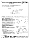
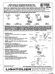
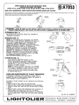
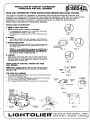
INSTRUCTION
INSTALLATION OF COMPACT FLUORESCENT
DOWNLIGHTS AND WALL WASHERS
SHEET NO.
IS:8054CL
0891
READ AND UNDERSTAND
This fixture
regulations.
is intended
To assure
THESE INSTRUCTIONS
for installation
full compliance
\
Page
BEFORE INSTALLING
in accordance
with the National
with local codes and regulations,
Electrical
FIXTURE.
Code
and
1 of 2
-
local
check with your local electrical
inspector before installation. To prevent electrical shock, turn off electricity at fuse box before
proceeding. This fixture is intended for ceiling mounting and is suitable for damp locations.
Retain
these
Instructions
INSTALLATION
for maintenance
reference.
-
OF DOWNLIGHT
A. INSTALL WHITE TRIM RING
NOTE Omit this sactlon If reflector is self-flenged.
1. For overlappin
trim installation
(Fig. 1), slip WHITE TRIM RING
over REFLEC#R,
as shown in Fig. 2 and 3.
2. For flangeless trim installation
(Fig. 4), WHITE TRIM RING is not
required.
@
FIG. 1
B. SNABIN
Align TABS on SOCKET CUP with openings in REFLECTORand
push in SOCKET CUP until RETAINING SPRING snaps in (Fig. 5).
,,$y
.—.
- 1
C. PUSH-UP REFLECTOR
1. Tilt REFLECTOR and insert SOCKET CUP into ceiling opening on
side opposite JUNCTION
into ceiling (Fig. 6).
..
BOX. Pivot REFLECTOR and push it up
WHITE
TRIM
RING
../“
REFLECTOR
OR LENS TRIM
FIG. 3
FIG. 2
N~E To remove REFLECTOR, disengsge the SOCKET CUP by
depressing the RETAINING SPRING (Fig. 5). Turn REFLECTOR
counterolockwlse
while pulling downward. After starting, use
both hands to ramov~ If desired. See Fig. 7.
D. LAMPING
lnserI lamp, tip first through hole in side of reflector opposite lamp
SOCKETS. Bring lamp to horizontal position, line up pins, and push
into socket (Fig.8). To relamp, carefully pull straight out of socket, tilt
base downward, and remove lamp.
::
.:.
.
Y.
,4.,..,-.
,,. ..
@
—
FK3. 4
INSTALLATION OF LENS WALL WASHER AND OPEN
WALL WASHER
NOTE. aafore Installing reflector, make sure the mountingframe IS
Installed with JUNCTION BOX away from the wall to ba illuminated
(Fig. 10A or 10B).
FOR OPEN
WALL WASHER
1. Remove two RETAINING SPRINGS
the MOUNTING FRAME (Fig 9).
that are near the JUNCTION
2. Insert two new RETAINING SPRINGS, that are provided
trim, into pocket of MOUNTING FRAME (Fig. 9A).
3. Then squeeze RETAINING
SPRING
into position
FIG. 5
BOX from
with the reflector
with a plier (Fig. 9A).
TO REMOVE
““E=Ju
m
wREFLEcTOR
FIG. 6
RETAINING
SPRING
REMOVED
1
m
FIG. 7
SOCKET
—
,.,,
,..
—
..+jf’
v
/
FIG. 8
*
FIG. 9
n
.,5-;:::’;+’
‘..:>~’
,, ,.
,, ,,,
,,,,,,
,.:,
~x.,:s
..
FIG. 9A
;2;~54CL
lNSTALIATION
OF COMPACT FLUORESCENT
DOWN LIGHTS AND WALL WASHERS (CONT’D)
A. SNAPIN
Page
LENS WALL WASHER
Align TABS on SOCKET CUP with openings in reflector and push in
SOCKET CUP until RETAINING SPRING snaps-in (Fig. 5).
B. INSTALL WHITE TRIM RING
NOTE Omit this section If reflector
SOCKET CUP
is self-flanged.
1. For overlapping trim installation (Fig. 1) slip WHITE RING over
LENS TRIM as shown in Fig. 2 and 3.
2. For flangeless trim installation
(Fig. 4), WHITE TRIM RING is not
required.
r
JUNCTION
BOX
REFL
LEAVE APPROX.
1“ EXPOSED
C. PUSH-UP REFLECTOR FOR LENS WALL WASHER
1. Tilt REFLECTOR and insert SOCKET CUP into ceiling opening on
side opposite JUNCTION BOX. Push REFLECTOR up leaving
approximately
one inch of the REFLE~R
exposed below the
CEILING LINE (Fia. 10A).
SPRINGS on LENS TRIM by squeezing
2. Compress TORSl~NTITE
with fingem. Insert into SLOTS in REFLECTOR and push up into
REFLECTOR until flush with ceiling (Fig. 11).
NOTE To remove REFLEC70R, lift LENS and pull LENS TRIM down
(Fig. 12), then disengage the SOCKET CUP by daprsssing the
RETAINING SPRING (Fig.5). lhrn REFLECTOR counterclockwise
while pulling downward. Aftar stafling, use both hands to remove.
See Fig. 7.
TITE
G
\
u“
BOX.
Pivot REFLECTOR
and push
straight
10A
OPEN WALL WASHER
JUNCTION
BOX
it up
NOTE To remove REFLECTOR, disengage the SOCK~
CUP by
daprassing the RETAINING SPRING (Fig. 5). 7urn REFLEC70R
counteroiockwise
while pulling downward. After starting, use
both hands to remove If dasired. Saa Fig. 7.
D. LAMPING
Line up pins and push into socket. To relamp, carefully
M
WALL TO BE ILLUMINATED
FIG.
PUSH-UP REFLECTOR FOR OPEN WALL WASHER
REFLECTOR and insert SOCKET CUP into ceiling opening on
1,Tilt
side opposite JUNCTION
into ceilina-.-,[Fia. 13).
~
*K
pull lamp
out.
CARE AND MAINTENANCE
OF A12AK@ REFLECIOR
If handling of reflectors with anodized or Alzak finish is required, the
use of clean white or plastic film gloves is recommended
to avoid
fingerprints.
Anodized or Alzak surfaces can be cleaned by the following methods
1. Wipe off with a soft, clean, dry, lint-free cloth.
2. Wipe off with a soft clean cloth dampened in mild detergent
--
WALL TO BE ILLUMINATED
FIG. 10B
solution. Rinse then wipe dry with lint-free cloth or paper towel.
3. Wipe off with a clean cloth dampened with a solution of wetting
agent and water (such as 2 oz. per gallon “Pluronic L62-LF” by
Wyandotte Products). Then wipe dry.
4. Or use a liquid wash such as Glass Wax”. Avoid gritty cleaning
agents.
FIG. 11
/-SOCKET
CUP
‘“’%lON
-Qi-REFLEcTOR
FIG. 13
2 of 2
FIG.
12
7
b