1
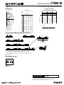
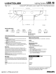
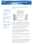
Lighting Systems
1BHFPG
F7000-18
'4FSJFT-JHIU5-PVWFS8BMM.PVOU
5
3.25”
(8.25cm)
4
3.698”
(9.39cm)
1
.750”
(1.91cm)
1.63”
(4.14cm)
1
1.304”
(3.31cm)
3.95” (10.03cm)
6. Louver Shielding
Ordering Information
Family
Series
Type
Lamps
FW7
4
4
1
4 = Block
w/ Lens
4 = Louver
1 = 1 Lamp
Color
Wattage
AL = Aluminum
WH = White
Complete Ordering Instructions below.
1 = 28W
2 = 54W
3 = 28W Dimming
4 = 28W EM
5 = 54W Dimming
6 = 54W EM
Voltage
1 = 120v
2 = 277v
Length
4 = 4’ (121.92cm)
8 = 8’ (243.84cm)
Features
Finish
1. Housing: Single piece of high purity extruded aluminum, a portion from
recycled material. Extruded acrylic lens reveal installed on the top of the
housing, runs the length of the housing.
2. Housing End: Die-cast aluminum, welded in place.
3. End Cap: Die-cast aluminum. Encloses the end of the run.
4. Lamps: F28T5 or F54T5HO as specified. By others. Installed from the ceiling
side of the luminaire.
5. Ballast: Electronic. Meets ANSI starting, end-of-life protection and sound
rating specifications. Low THD.
6. Shielding: Integral, regressed flat louver blades punched and formed from
fixture housing, finished to match, no light leaks. Blades are 0.56” (1.42cm)
high on 0.75” (1.91cm) centers.
Powder-coated, baked enamel, white or aluminum, as specified.
Electrical
Connections: Pre-wired with 18 gauge wires and polarized cannon plug connectors for simultaneous mechanical/electrical connection.
Emergency Battery Pack: 90 minute operation, 700 lumens for 54W and 520
lumens for 28W.
Dimming: Advance Mark X standard (no additional wires required); use compatible dimmer. Dimming ballasts using additional control wires (e.g. Lutron Hi-Lume
or ECO-10, Osram) can be used; consult factory and use X4 or X5 power feeds
with additional leads, as appropriate. Ballast not to exceed 1.25” (3.18cm) wide by
1.20” (3.05cm) high.
iGEN: F7000 accepts iGEN (DALI) with supplemental 2-wire control technology.
Use with X5 power feed.
Power Tray: Code-gauge, die-formed steel, pre-paint white enamel finish;
secured by quarter-turn fasteners for easy access to wiring. Holds ballasts, sockets, and wiring. Accepts ballasts up to 1.25” (3.18cm) wide by 1.20” (3.05cm) high.
Mounting
Each module includes two wall-mounting brackets. Bracket hole pattern accommodates junction box (single gang box rotated 90 degrees) or other appropriate
mounting method using customer supplied fasteners.
Labels
UL, cUL and I.B.E.W.
Ordering Instructions
Individual Fixtures:
1. Order one MODULE.
2. Order one END SET.
Continuous Rows:
1. Order the appropriate number of MODULES for the complete run.
2. Order one END SET.
Job Information
Type:
Job Name:
Cat. No.:
Lamp(s):
Notes:
Factory installed ballast disconnect allows the ballast to be disconnected from and
reconnected to incoming power under load without turning the entire circuit off.
"JSQPSU3PBE'BMM3JWFS."t
t'BY
We reserve the right to change details of design, materials and finish.
XXXMJHIUPMJFSDPN½1IJMJQT(SPVQt &
Lighting Systems
1BHFPG
'4FSJFT-JHIU5-PVWFS8BMM.PVOU
Performance
ZONE
DEG.
0
150
160
170
180
120
80
90
100
110
70
60
50
40
840
0
10
30
20
REPORT NO.: ITL54690.IES
LAMPS: 1-F54T5
LUMENS: 5000 each
EFFICIENCY: 81.7%
CAT. NO.: F7441WH214
45
67
90
618
612
559
488
394
282
173
118
78
43
31
98
313
433
543
621
664
688
700
710
710
618
606
532
433
319
206
123
80
42
8
0
35
155
285
412
515
600
661
700
713
710
80%
CANDELAS
0
13
1
0
5
15
25
35
45
55
65
75
85
90
95
105
115
125
135
145
155
165
175
180
22
618
631
701
787
712
462
286
191
133
107
92
127
350
611
818
841
844
822
756
699
710
618
627
672
717
667
442
264
171
129
98
84
126
355
613
789
817
828
813
749
700
710
618
624
618
597
548
402
225
144
108
74
61
113
345
581
675
738
771
762
727
707
710
ROOM CAVITY RATIO
40
210
630
COEFFICIENTS OF UTILIZATION
% EFFECTIVE CEILING CAVITY REFLECTANCE
CANDLEPOWER
CANDLEPOWER CURVE
420
F7000-18
50
85
73
65
57
50
45
40
36
33
30
28
0
1
2
3
4
5
6
7
8
9
10
30
85
70
60
51
45
39
34
30
27
24
22
70%
WALL REFLECTANCE
50 30 10
76 76 76
67 64 62
58 54 50
51 47 43
46 41 36
41 35 31
37 31 28
33 28 24
30 25 21
28 22 19
26 20 17
10
85
67
56
47
40
34
29
26
23
20
18
50%
50
61
53
47
42
37
33
29
27
25
23
21
30
61
51
44
38
33
29
26
23
21
19
17
10
61
49
42
35
30
26
23
20
18
16
14
20% FLOOR CAVITY REFLECTANCE
DISTRIBUTION
Zone
Lumens
0 - 90
1339
90 - 180
2748
0 - 180
4087
% Lamp
26.6
55.1
81.7
%Luminaire
33.0
67.0
100.0
Fixture Lengths & Mounting Reflected (Plan View)
2'-8"
(81.28cm)
6'-8" (203.20cm)
16.00" (40.64cm)
4'-3" (129.54cm)
8'-3" (251.46cm)
6'-8" (203.20cm)
1'-4"
(40.64cm)
2'-8"
(81.28cm)
3/4"
(1.91cm)
JOINING DETAIL
GAP BETWEEN FIXTURES
12'-3" (373.38cm)
6'-8" (203.20cm)
1'-4"
(40.64cm)
6'-8" (203.20cm)
16'-3" (495.30cm)
1-1/2"
(3.81cm)
6'-8" (203.20cm)
1'-4"
(40.64cm)
6'-8" (203.20cm)
1'-4"
(40.64cm)
2'-8"
(81.28cm)
20'-3" (617.22cm)
3/8" (0.95cm)
END OF ROW DETAIL
Recommended mounting is a single gang outlet box rotated 90 degrees at the
feed point. Remaining mounting points could be outlet boxes as well, or a couple
of holes per mounting point spaced 3-1/4” (8.26cm) at 1-3/4” (4.45cm) above the
bottom of fixture.
Mounting Accessories
Wall Mount End Set
FW7EWH = White
FW7EAL = Aluminum
Job Information
Type:
"JSQPSU3PBE'BMM3JWFS."t
t'BY
We reserve the right to change details of design, materials and finish.
XXXMJHIUPMJFSDPN½1IJMJQT(SPVQt &