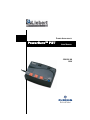
1
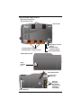
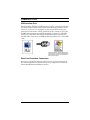
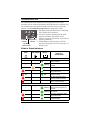
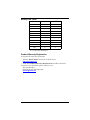
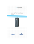
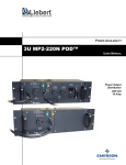
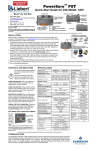
POWER AVAILABILITY
PowerSure™ PST
USER MANUAL
350-500 VA
120V
TABLE OF CONTENTS
IMPORTANT SAFETY INSTRUCTIONS . . . . . . . . . . . . . . . . . . . . . 1
INTRODUCTION AND SYSTEM DESCRIPTION . . . . . . . . . . . . . . . 4
Top and Side Views of UPS . . . . . . . . . . . . . . . . . . . . . . . . . . . . . 5
MAJOR COMPONENTS . . . . . . . . . . . . . . . . . . . . . . . . . . . . . . . 6
Transient Voltage Surge Suppression (TVSS) & EMI / RFI
Filters . . . . . . . . . . . . . . . . . . . . . . . . . . . . . . . . . . . . . . . . . . . . . . 6
Transfer Switch . . . . . . . . . . . . . . . . . . . . . . . . . . . . . . . . . . . . . . 6
Battery Charger . . . . . . . . . . . . . . . . . . . . . . . . . . . . . . . . . . . . . . 6
Battery . . . . . . . . . . . . . . . . . . . . . . . . . . . . . . . . . . . . . . . . . . . . . 6
Inverter . . . . . . . . . . . . . . . . . . . . . . . . . . . . . . . . . . . . . . . . . . . . . 6
WHAT’S INCLUDED . . . . . . . . . . . . . . . . . . . . . . . . . . . . . . . . . 7
INSTALLATION. . . . . . . . . . . . . . . . . . . . . . . . . . . . . . . . . . . . . 8
CONTROLS AND INDICATORS . . . . . . . . . . . . . . . . . . . . . . . . . 10
ON/OFF/Alarm Silence Button . . . . . . . . . . . . . . . . . . . . . . . . 10
Status Indicators: Utility/Battery, Fault . . . . . . . . . . . . . . . . . 11
Utility/Battery Indicator (Green) . . . . . . . . . . . . . . . . . . . . . . . . . 11
Site Wiring Fault Indicator (Amber) . . . . . . . . . . . . . . . . . . . . . . . 11
Fault Indicator (Red) . . . . . . . . . . . . . . . . . . . . . . . . . . . . . . . . . . . 11
Location and Status of Indicators . . . . . . . . . . . . . . . . . . . . . . . . . 11
MODES OF OPERATION . . . . . . . . . . . . . . . . . . . . . . . . . . . . . 12
Normal Mode . . . . . . . . . . . . . . . . . . . . . . . . . . . . . . . . . . . . . . . 12
Battery Mode . . . . . . . . . . . . . . . . . . . . . . . . . . . . . . . . . . . . . . . 12
COMMUNICATIONS . . . . . . . . . . . . . . . . . . . . . . . . . . . . . . . . 13
USB Interface Port. . . . . . . . . . . . . . . . . . . . . . . . . . . . . . . . . . . 13
Data Line Protection Connectors . . . . . . . . . . . . . . . . . . . . . . . 13
MAINTENANCE . . . . . . . . . . . . . . . . . . . . . . . . . . . . . . . . . . . 14
Cleaning the UPS. . . . . . . . . . . . . . . . . . . . . . . . . . . . . . . . . . . . 14
Maintaining Batteries . . . . . . . . . . . . . . . . . . . . . . . . . . . . . . . . 14
TROUBLESHOOTING . . . . . . . . . . . . . . . . . . . . . . . . . . . . . . . 15
Guide to Status Indicators. . . . . . . . . . . . . . . . . . . . . . . . . . . . . 15
Troubleshooting Chart . . . . . . . . . . . . . . . . . . . . . . . . . . . . . . . . 16
SPECIFICATIONS . . . . . . . . . . . . . . . . . . . . . . . . . . . . . . . . . . 17
Battery Run Times. . . . . . . . . . . . . . . . . . . . . . . . . . . . . . . . . . . 18
Product Warranty Registration. . . . . . . . . . . . . . . . . . . . . . . . . 18
i
IMPORTANT SAFETY INSTRUCTIONS
SAVE THESE INSTRUCTIONS
This manual contains important safety instructions that should be followed during the installation and maintenance of the Uninterruptible
Power System (UPS) and its batteries. Please read this manual thoroughly before attempting to install or operate this UPS.
Read all safety, installation, and operating instructions before operating the UPS. Adhere to all warnings on the unit and in this manual.
Follow all operating and user instructions.
This equipment is designed for Commercial, Industrial or Residential
use. Liebert Corporation neither recommends nor knowingly sells this
product for use in life support applications or with other designated
critical devices.
This equipment can be installed and operated by individuals without
previous training.
!
WARNING
SAFETY PRECAUTIONS
• To prevent the risk of fire or electric shock, install the UPS
in a temperature and humidity controlled room, free of
conductive contaminants, moisture, flammable liquids,
gases and corrosive substances.
• Operate the UPS only from a properly grounded (earthed)
120VAC, 60Hz AC supply.
• To reduce the risk of electric shock, do not remove the
cover, as it has no user-serviceable parts inside except the
internal battery pack. Some components are live, even
when AC power is disconnected. For service, contact a
qualified technician.
1
!
!
CAUTION
Although your UPS has been designed and manufactured to
assure personal safety, improper use may result in electrical
shock or fire. To ensure safety, please observe the following
rules:
• Turn off and unplug your UPS before cleaning. Do not use
liquid or aerosol cleaners. A dry cloth is recommended to
remove dust from the surface of your UPS.
• Do not install or operate your UPS in or near water.
• Do not place your UPS on an unstable cart, stand or table.
• Do not place your UPS in direct sunlight or near heat
emitting sources.
• Never block or insert any objects into the ventilation holes
or other openings of the UPS. Keep all vents free of dust
accumulation that could restrict airflow.
• Do not place UPS power cord in any area where it may be
damaged by heavy objects.
• Placing magnetic storage on the top of the UPS may result
in data corruption.
CAUTION
If your UPS demonstrates any of the following conditions,
turn off and unplug your UPS from the outlet and contact
your local dealer, Liebert representative, or Liebert
Worldwide Support Group.
• The power cord is damaged.
• Liquid has been spilled on the UPS.
• The circuit breaker or fuse opens frequently.
• The UPS does not operate in accordance with the user
manual.
Provided is a USB cable for connection to a computer. Store in a safe
place if not required at this time.
2
CONDITIONS OF USE: The input receptacle must be within 6 feet
(1.8 meters) of the UPS.
Your UPS provides conditioned power to connected equipment. Maximum load must not exceed that shown on UPS rating label. If uncertain, consult your local dealer, Liebert representative or the Liebert
Worldwide Support Group.
The equipment can be installed and operated by individuals without
previous training.
!
CAUTION
BATTERY HANDLING PRECAUTIONS
Servicing of batteries should be performed or supervised by
personnel knowledgeable of batteries and required
precautions. Keep unauthorized personnel away from the
batteries.
A battery can present a risk of electrical shock and high
short-circuit current. The following precautions should be
observed when working on batteries:
• Remove watches, rings, and other metal objects.
• Use tools with insulated handles.
• Do not dispose battery or batteries in a fire. The battery
may explode.
• Do not open or mutilate the battery or batteries. Released
electrolyte is harmful to skin and eyes. It may be toxic.
• When replacing the battery, use same number and type of
battery as the suitable recommended type of battery listed
in specification table in back of this manual.
• Handle, transport and recycle batteries in accordance with
local regulations.
3
INTRODUCTION AND SYSTEM DESCRIPTION
Congratulations on your choice of the Liebert PowerSure™ PST Uninterruptible Power System (UPS). It provides filtered AC power to sensitive electronic equipment and other critical loads.
The PowerSure PST is an off-line UPS designed for desktop applications. It provides perfect one-to-one power protection for electronic
equipment such as PCs, point-of-sale displays, home office equipment
and similar electronic gear. The PowerSure PST is available in two (2)
sizes: 350 and 500VA at 120VAC.
PowerSure PST models are available for 120VAC and 230VAC supply
voltages and loads. Please verify that this model matches your AC
Utility and load voltage requirements.
NOTE
This device complies with part 15 of the FCC Rules.
Operation is subject to the following two conditions: (1) This
device may not cause harmful interference, and (2) this device
must accept any interference received, including interference
that may cause undesired operation.
This equipment uses, generates and can radiate radio
frequency energy and, if not installed and used in accordance
with the instructions, may cause harmful interference with
radio communications. However, there is no guarantee that
interference will not occur in a particular installation.
If this equipment does cause harmful interference to radio or
television reception, which can be determined by turning the
equipment off and on, the user is encouraged to try to correct
the interference by one or more of the following measures:
• Reorient or relocate the receiving antenna.
• Increase the separation between the UPS and the receiver.
• Connect the UPS into an outlet on a circuit different from
the one on which the receiver is connected.
4
Top and Side Views of UPS
Black output receptacles
Surge protection only
TOP OF UPS
Orange output receptacles
Battery backup + surge protection
Utility/Battery Indicator
(Green)
Site Wiring Fault
Indicator (Amber)
Fault Indicator (Red)
RIGHT SIDE OF UPS
USB
interface
port
LEFT SIDE OF UPS
Power Cord
6.5 ft (2 m)
Data Line
Protection
Connectors
(IN, OUT, OUT)
Phone/fax/
modem/DSL
Refer to Bottom for
Cautionary Markings
Circuit Protector
5
MAJOR COMPONENTS
Input
L
TVSS &
EMI/RFI
Filters
Transfer
Switch
Battery
Charger
Battery
Output
L
Inverter
N
N
G
G
Transient Voltage Surge Suppression (TVSS) & EMI / RFI
Filters
These UPS components provide surge protection and filter electromagnetic interference (EMI) and radio frequency interference (RFI).
They minimize surges or interference present in the utility line and
keep the sensitive equipment protected.
Transfer Switch
In Normal mode the Transfer Switch passes utility AC power to the
connected load. When input utility voltage or frequency is outside
acceptable limits, the transfer switch activates and transfers the UPS
to battery.
Battery Charger
In Normal mode, the Battery Charger converts utility AC power into
regulated DC power to float charge the battery. It is continuously
charging the battery whenever the UPS is plugged into a power outlet
and utility power is within acceptable limits—even if the UPS is
turned OFF.
Battery
The PowerSure PST utilizes a valve-regulated, nonspillable, lead acid
battery. To optimize battery life, operate the UPS in an ambient temperature of 68°-77°F (20°-25°C).
Inverter
When utility power fails, the Inverter draws energy from the battery
and inverts it into a regulated stepped sinewave supplying power for
equipment connected to the orange receptacles.
6
WHAT’S INCLUDED
The PowerSure PST is shipped with the following items:
• PowerSure PST user manual
• USB cable, 6 ft. (1.8m)
• RJ-11 cord, 7 ft. (2.1m)
• Warranty card
USB cable
6-ft. (1.8m)
PowerSure PST
7
RJ-11 cord
7-ft. (2.1m)
INSTALLATION
This UPS is designed for data processing equipment. Maximum load
must not exceed that shown on the UPS rating label. Do not connect
equipment that could overload the UPS or draw half-wave current
from the UPS, for example: electric drills, vacuum cleaners, laser
printers or hair dryers. Your total load earth leakage current must not
exceed 3.5 mA. Most data processing equipment meets this requirement if you use no more than two pieces of equipment. If uncertain
about your load, consult your local dealer, Liebert representative, or
Liebert Worldwide Support Group.
1. Visually inspect the UPS for freight damage. Report damage to the
carrier and your local dealer, Liebert representative or the Liebert
Worldwide Support Group.
2. Decide where to place the PowerSure PST. Install the UPS indoors
in a controlled environment, where it cannot be accidentally turned
off. Place it in an area of unrestricted airflow around the unit, away
from water, flammable liquids, gases, corrosives, and conductive
contaminants. Maintain an ambient temperature range of 32°F to
104°F (0°C to 40°C).
NOTE
UPS operation in temperatures above 77°F (25°C) reduces
battery life.
Plug this type of equipment into black
receptacles ONLY.
Inkjet
Printer
Scanner
FAX
Machine
Plug computers, monitors & network hubs
into orange receptacles.
3. Plug the PowerSure PST’s attached 6.5-ft. (2m) power cord into an
AC outlet. Check that the Site Wiring Fault Indicator is not illuminated. If it is lit, refer to the Troubleshooting section.
4. Plug any computers and monitors into the orange battery backed up
receptacles.
8
Other office machines that do not exceed the capacity of the UPS—
inkjet printers, scanners and fax machines—may be plugged into
either of the two (2) black receptacles, which provide surge protection only.
5. Connect Phone/Fax/DSL/Internet/Modem devices to data line connectors.
r to Bottom for
ionary Markings
6. Press and release the ON/OFF/Alarm Silence button to turn on the
UPS. The UPS will beep and the Utility/Battery Indicator will illuminate (green).
7. Turn on connected equipment.
8. Connect the USB cable provided with the UPS to the USB ports on
the PST and your computer. The PST will work automatically with
your built-in power management software on Windows XP and 2000
and Mac OS 10.2 or later (see USB Interface Port section for
details).
NOTE
When using the communication features on this UPS, ensure
the cabling connected to the UPS communications ports are
kept separated from the power leads to the UPS input and
output.
9
CONTROLS AND INDICATORS
ON/OFF/Alarm Silence Button
This button controls output power to the
connected load and has three functions:
• ON
• OFF
• Alarm Silence
ON/OFF/Alarm Silence
ON
When the UPS is off, pressing the main ON/OFF button for
more than two seconds will start the UPS, and an audible
alarm sounds briefly. The UPS is capable of starting on battery (battery start).
OFF
When the UPS is on (in either Normal or Battery mode),
pressing the main ON/OFF button for more than
two (2) seconds will shut down the UPS. An audible alarm
sounds briefly.
Alarm When a UPS audible alarm is active, pressing and releasing
Silence the main ON/OFF button will silence the active audible
alarm, whether utility power is present or not. Once the
alarm silence function has been activated, all active audible
alarms—except for low battery or overload conditions—will
remain silenced until a new alarm condition is detected.
NOTE
Do not hold ON/OFF button down for more than 2
seconds or the UPS will shut down.
10
Status Indicators: Utility/Battery, Fault
There are two (2) status indicators on the top panel of the UPS, as
shown in the diagram below. Each indicator illuminates to specify the
status of the UPS (see Troubleshooting section for details).
Utility/Battery Indicator (Green)
The Utility/Battery Indicator illuminates when the UPS is operating
in Normal mode, supplying power to connected loads. The Utility/Battery Indicator flashes when the UPS is operating in Battery mode.
Site Wiring Fault Indicator (Amber)
The Site Wiring Fault Indicator flashes amber when the UPS detects
a line-neutral reversal or a poor neutral-ground bonding.
Fault Indicator (Red)
The Fault Indicator illuminates when the UPS detects an internal
fault. It flashes if the UPS detects an overload condition.
Location and Status of Indicators
Utility/Battery Indicator (Green)
Site Wiring Fault Indicator (Amber)
Fault Indicator (Red)
11
MODES OF OPERATION
Normal Mode
-
+
During Normal mode operation, the PowerSure PST supplies conditioned, computergrade power to the connected equipment: utilContinuous LED
ity power passes through the TVSS circuitry,
illumination denotes
EMI/RFI filters and then through the TransNormal Mode
fer Switch to the connected equipment.
When the UPS is in Normal mode, the
Utility/Battery Indicator illuminates green.
The PowerSure PST continuously monitors the batteries to maintain
them in a fully charged state. The battery charger operates whenever
AC power is present, even if the UPS is switched off. The UPS performs an automatic battery test after it has been operating continuously for two (2) weeks.
Battery Mode
+
-
The UPS switches to Battery mode in the
event of an extreme voltage/frequency condition or complete utility failure. The battery
system supplies power through the Inverter to
Flashing LED
generate power for connected equipment.
When the UPS is in Battery mode, the Utility/ illumination denotes
Battery Mode
Battery Indicator flashes green and an alarm
sounds every 5 seconds.
When a low battery condition occurs, the Battery Indicator continues
to flash green and the alarm sounds every half-second. Low battery
warning is initiated when approximately two (2) minutes of battery
run time are remaining. For more information, refer to Troubleshooting section.
!
CAUTION
Turning off the UPS while in either Normal mode or Battery
mode will result in the loss of output power.
NOTE
Once utility power is restored, the UPS resumes normal
operation. At this time, the battery charger begins recharging
the battery. The UPS is capable of OFF-State charging, i.e.,
with utility power, the UPS will charge the batteries as long
as it is plugged in.
12
COMMUNICATIONS
USB Interface Port
The PowerSure PST has a USB interface port for communication that
will work with the built-in Microsoft Power Manager software on the
user’s PC, if the PC is so equipped. It will provide UPS status and
manages the automatic, orderly shutdown of the computer. The UPS
(USB) communications meets HID standard, version 1.11. All USB
models are compatible with Microsoft Windows 2000, Windows XP
and Mac OS 10.2 or later. All USB models ship with a 6 ft. (1.8m) USB
cable.
Microsoft, Windows, and the Windows logo
are trademarks, or registered trademarks of
Microsoft Corporation in the United States
and/or other countries.
Data Line Protection Connectors
Data line (1 input & 2 outputs) connectors are located on the rear of
the UPS and provide transient voltage surge suppression (TVSS) for
Phone/Fax/DSL/Internet/Modem devices.
13
MAINTENANCE
The PowerSure PST UPS requires very little maintenance. Follow
these practices to prevent problems.
Cleaning the UPS
The following will help ensure trouble-free operation for years:
• Vacuum dust from the ventilation intake occasionally.
• Wipe the cover periodically with a dry cloth.
Maintaining Batteries
The batteries are valve-regulated, nonspillable, lead acid and must be
kept charged to retain their design life. The UPS continuously charges
the batteries when connected to the utility supply, even while the UPS
is switched off.
When storing the UPS, it is recommended to plug in UPS for at least
24 hours every four to six months to ensure full recharge of the batteries.
14
TROUBLESHOOTING
The information below indicates various symptoms a user may
encounter in the event the PowerSure PST experiences a problem. Use
this information to determine whether external factors caused the
problem. See Troubleshooting Chart for suggested remedy.
1. The Fault Indicator illuminates, indicating
the UPS detected a problem.
2. An alarm sounds, alerting that the UPS
requires attention. The alarm can be
silenced except for low battery and overload
warning conditions.
Fault
Utility/Battery
Indicator
Indicator
3. Utility/Battery Indicator may be illuminated as a diagnostic aid to the operator, as
Site Wiring
Fault Indicator
shown below:
Guide to Status Indicators
Fault
(Red)
Site Wiring Utility/Battery
Fault (Amber)
(Green)
-
+
!
Diagnosis/
Audible Alarm
Normal Mode
—
—
—
—
UPS is operating in Normal
Mode; no beep.
Test has been initiated;
Flashing Battery
no beep.
—
Flashing
ON
Site Wiring Fault; no beep.
Flashing
—
ON
ON
—
ON
Flashing
—
—
ON
—
—
The unit is overloaded; beep
every half-second
The UPS has failed;
continuous beep
Unit has shut down due to
overload; continuous beep
The UPS shut down due to
failure; continuous beep
ON
Battery Mode
—
—
—
—
Flashing
—
ON
—
The UPS is operating in
Flashing Battery mode; beep every 5
seconds.
battery is low; beep every
Flashing UPS
half-second
unit is overloaded; beep
Flashing The
every half-second
UPS has failed;
Flashing The
continuous beep
15
Troubleshooting Chart
If the UPS fails to operate properly, turn off the unit and repeat the
steps in the Installation section of this manual. If the problem persists, refer to the chart below:
Problem
UPS will not
start
UPS starts
on battery,
but will not
switch to AC
Cause
Solution
Check the circuit protector on the side
of the UPS. If it is tripped, reset it and
restart the UPS.
For further help, call your local dealer,
Liebert representative or the Liebert
Worldwide Support Group.
Plug in power cord securely.
Reset the circuit protector and restart
the UPS.
Have the utility receptacle checked by
a qualified electrician.
Wait until the voltage rises to an
appropriate level or have the utility
receptacle checked by a qualified
electrician.
Wait until voltage lowers to an
appropriate level or have the utility
receptacle checked by a qualified
electrician.
Check the circuit protector on the rear
of the UPS. If it is tripped, reset it and
restart the UPS.
If the problem persists, disconnect
some of the equipment from your
UPS—the total wattage of your
equipment must not exceed the
capacity of the UPS. For further help,
call your local dealer, Liebert
representative or the Liebert
Worldwide Support Group.
Overload/
Short circuit
UPS not plugged in
Circuit protector
tripped
Power not available
at utility receptacle
Input voltage below
threshold
AC overvoltage
Overload/
Short circuit
UPS shuts
down, Fault
Indicator lit
Internal UPS fault
Site Wiring
Fault
Indicator
illuminated
Line-neutral
reversal/Poor
ground connection
Have the utility checked by a qualified
electrician.
UPS not
providing
expected
backup time
Overload
Battery not charged
due to a recent
outage
Reduce load.
Recharge battery.
16
SPECIFICATIONS
Model Number
Model Rating VA / W
DIMENSIONS: in (mm)
Unit W x D x H
Shipping W x D x H
WEIGHT: lbs (kg)
Unit
Shipping
INPUT AC PARAMETERS
Surge Protection
Voltage Range Without
Battery Operation
Frequency
Input Power Cord
OUTPUT AC PARAMETERS
Output Receptacles
Voltage (Battery Mode)
Output Current
Waveform (Battery Mode)
Frequency (Battery Mode)
Overload Warning
Overload Shutdown
BATTERY PARAMETERS
Type
Quantity x Voltage x Rating
Transfer Time
Back-up Time:
Full load
Half load
Recharge Time
ENVIRONMENTAL
Operating Temperature
Storage Temperature
Relative Humidity
Operating Elevation
Audible Noise
AGENCY
Safety
PA350-120U
350/225
PA500-120U
500 / 300
6.6 x 9.8 x 3.7
(168 x 250 x 95)
9.4 x 13.8 x 5.6
(238 x 350 x 142)
6.6 x 9.8 x 3.7
(168 x 250 x 95)
9.4 x 13.8 x 5.6
(238 x 350 x 142)
11.7 (5.3)
12.1 (5.5)
13.5 (6.1)
13.9 (6.3)
603J
98VAC - 140VAC ±3VAC
57 - 63 Hz (±0.4Hz)
6.5 ft.attached, w/ NEMA 5-15 P
(3) NEMA 5-15R (orange) battery backup+surge protection
(2) NEMA 5-15R (black) surge protection
120VAC ±8%
2.9 A
4.2 A
Stepped Sinewave
60Hz ±1Hz
>100%
>110%
Valve-regulated, nonspillable, lead acid
1 x 12V x 5 Ah
1 x 12V x 7 Ah
4 – 6 ms typical
At 77°F (25°C), resistive loading, w/ fully charged batteries:
5 minutes
3 minutes
16 minutes
15 minutes
12 hours to 90% capacity, after full discharge into
resistive load
+32°F to + 104°F (0°C to +40°C)
+5°F to + 122°F (-15°C to +50°C)
0% to 95%, non-condensing
Up to 10,000 ft. (3000 m) at 86°F (30°C) w/o derating
< 40 dBA, at 1 meter
UL 1778, c-UL Listed
ANSI C62.41, Category A, Level 3, (IEEE 587, Category A);
Surge
EN61000-4-5, Level 3, Criteria A
ESD
EN61000-4-2, Level 3, Criteria A
Susceptibility
EN61000-4-3, Level 2, Criteria A
Electrical Fast Transient/Burst
EN61000-4-4, Level 3, Criteria A
Emissions
FCC Part 15, Subpart B, Class B
Harmonics
EN61000-3-2
Conducted Immunity
EN61000-4-6
Flicker
EN61000-3-3
Transportation
ISTA Procedure 1A
17
Battery Run Times
Load %
350VA
500VA
5
168
318
10
87
84
20
51
48
30
29
28
40
20
18
50
16
15
60
11
10
70
9
8
80
7
6
90
6
4
100
5
3
Note: Approximate discharge times are in minutes and
at 77°F (25°C) with resistive load.
Product Warranty Registration
To register for warranty protection:
• Visit the Quick Links section of our Web site at:
http://www.liebert.com
• Click on Product Warranty Registration and fill in the form.
If you have any questions, please contact us at:
US: 800-222-5877
Outside the US: 614-841-6755
[email protected]
18
POWER AVAILABILITY
PowerSure™ PST
USER MANUAL
The Company Behind the Products Technical Support/Service
With over a million installations around the globe,
Liebert is the world leader in computer protection
systems. Since its founding in 1965, Liebert has
developed a complete range of support and
protection systems for sensitive electronics:
•
•
•
•
•
Environmental systems—close-control air
conditioning from 1 to 60 tons
Power conditioning and UPS with power
ranges from 300 VA to more than 1000 kVA
Integrated systems that provide both
environmental and power protection in a
single, flexible package
Monitoring and control—from systems of any
size or location, on-site or remote
Service and support through more than 100
service centers around the world and a 24/7
Customer Response Center
While every precaution has been taken to ensure
the accuracy and completeness of this literature,
Liebert Corporation assumes no responsibility and
disclaims all liability for damages resulting from use
of this information or for any errors or omissions.
© 2003 Liebert Corporation
All rights reserved throughout the world.
Specifications subject to change without notice.
® Liebert and the Liebert logo are registered
trademarks of Liebert Corporation. All names
referred to are trademarks or registered
trademarks of their respective owners.
SL-23275 (3/03) Rev. 1
Web Site
www.liebert.com
Monitoring
800-222-5877
[email protected]
Outside the US: 614-841-6755
Single-Phase UPS
800-222-5877
[email protected]
Outside the US: 614-841-6755
Three-Phase UPS
800-543-2378
[email protected]
Environmental Systems
800-543-2778
Outside the United States
614-888-0246
Locations
United States
1050 Dearborn Drive
P.O. Box 29186
Columbus, OH 43229
Italy
Via Leonardo Da Vinci 8
Zona Industriale Tognana
35028 Piove Di Sacco (PD)
+39 049 9719 111
Fax: +39 049 5841 257
Asia
23F, Allied Kajima Bldg.
138 Gloucester Road
Wanchai
Hong Kong
+852 2 572 2201
Fax: +852 2 831 0114