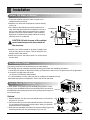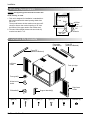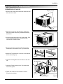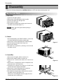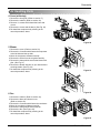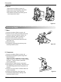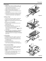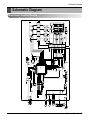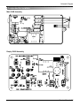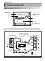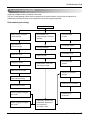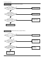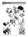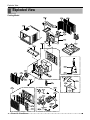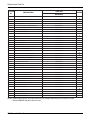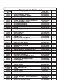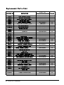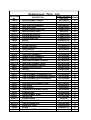
1
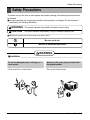
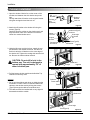
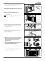
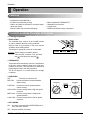
website http://www.lgservice.com
LG
LG Room
Air Conditioner
SERVICE MANUAL
MODEL: WG1805RY6,RAD-183A
WG2405RY6,RAD-243A
CAUTION
• BEFORE SERVICING THE UNIT, READ THE SAFETY
PRECAUTIONS IN THIS MANUAL.
• ONLY FOR AUTHORIZED SERVICE PERSONNEL.
Air Conditioner Service Manual
TABLE OF CONTENTS
Safety Precautions..........................................................................................................................................3
Dimensions .....................................................................................................................................................5
Symbols Used in this Manual .....................................................................................................................5
Outside Dimensions ...................................................................................................................................5
Product Specifications ..................................................................................................................................6
Installation .......................................................................................................................................................7
Select the Best Location ...........................................................................................................................7
Installation Check .......................................................................................................................................7
How to Secure the Drain Pipe ....................................................................................................................7
Window Requirements ...............................................................................................................................8
Installation Kits Contents............................................................................................................................8
Suggested Tool Requirements ...................................................................................................................9
Cabinet Installation...................................................................................................................................10
Operation ......................................................................................................................................................12
Features ...................................................................................................................................................12
Control Locations Function of Controls ....................................................................................................12
Disassembly ..................................................................................................................................................14
Mechanical Parts......................................................................................................................................14
Air Handling Parts ....................................................................................................................................15
Electrical Parts .........................................................................................................................................16
Refrigerating Cycle...................................................................................................................................18
Schematic Diagram.......................................................................................................................................21
Electronic Control Device .........................................................................................................................21
Wiring Diagram.........................................................................................................................................22
Components Lation ..................................................................................................................................23
Troubleshooting Guide .................................................................................................................................24
Piping System ..........................................................................................................................................24
Troubleshooting Guide .............................................................................................................................25
Room Air Conditioner Voltage Limits........................................................................................................31
Exploded View ..............................................................................................................................................34
Replacement Parts List ................................................................................................................................36
2 Room Air Conditioner
Safety Precautions
Safety Precautions
To prevent injury to the user or other people and property damage, the following instructions must
be followed.
■ Incorrect operation due to ignoring instruction will cause harm or damage. The seriousness is
classified by the following indications.
WARNING
This symbol indicates the possibility of death or serious injury.
CAUTION
This symbol indicates the possibility of injury or damage to property only.
■ Meanings of symbols used in this manual are as shown below.
Be sure not to do.
Be sure to follow the instruction.
WARNING
■ Installation
Do not use damaged power cord plugs, or a
loose socket.
• There is risk of fire or electric shock.
Always use the power plug and socket with
the ground terminal.
• There is risk of electric shock.
Service Manual 3
Safety Precautions
Do not modify or extend the power cord.
• There is risk or fire or electric shock.
Do not install, remove, or re-install the unit by
yourself.
• There is risk of fire, electric shock, explosion, or injury.
Be cautious when unpacking and installing
the product.
• Sharp edges could cause injury. Be especially careful
of the case edges and the fins on the condenser and
evaporator.
Do not store or use flammable gas or combustibles near the air conditioner.
• There is risk of fire or failure of product.
Sharp edges
Gasolin
Be sure the installation area does not deteriorate with age.
• If the base collapses, the air conditioner could fall with
it, causing property damage, product failure, and personal injury.
4 Room Air Conditioner
Dimensions
Dimensions
Symbols Used in this Manual
This symbol alerts you to the risk of electric shock.
This symbol alerts you to hazards that could cause harm to the
air conditioner.
NOTICE
This symbol indicates special notes.
Outside Dimensions
660
428
675 (770)
Model
18K Btu
24K Btu
Dimension
W
mm(inch)
660(26")
660(26")
H
mm(inch)
428(16 27/32")
428(16 27/32")
D
mm(inch)
675(26 9/18")
675(269/18")
Service Manual 5
Specfications
Product Specifications
Table -1
MODELS
ITEMS
WG2405RY7
WG1805RY6
POWER SUPPLY
1Ø, 208/230V, 60Hz
COOLING CAPACITY
17,500/18,000
23,500/23,800
INPUT
1,800/1,850
2,760/2,800
9.7
8.5
RUNNING CURRENT
REFRIGERANT (R-22) CHARGE(g)
OPERATING
TEMPERATURE
720g(25.4oz)
830g(29.3oz)
INDOOR(°C)
27(DB),19(WB)
OUTDOOR(°C)
35(DB),24(WB)
EVAPORATOR
2 ROW 15 STACKS
LOUVERED-FIN TYP
CONDENSER
2 ROW 19 STACKS,LOUVERED-FIN TYPE
L-BENDING TYPE
FAN, INDOOR
TURBO
FAN, OUTDOOR
PROPELLER TYPE FAN WITH SLINGER-RING
FAN SPEEDS, FAN/COOLING
3/3
FAN MOTOR
6 POLES
OPERATION CONTROL
WIRELESS REMOCN
ROOM TEMP. CONTROL
THERMISTOR
AIR DIRECTION CONTROL
VERTICAL LOUVER(RIGHT & LEFT)
HORIZONTAL LOUVER(UP & DOWN)
CONSTRUCTION
PROTECTOR
SLIDE IN-OUT CHASSIS
COMPRESSOR
INTERNAL OVERLOAD PROTECTOR
FAN MOTOR
INTERNAL THERMAL PROTECTOR
POWER CORD
3 WIRE WITH GROUNDING
CORD-CONNECTED TYPE(ATTATCHMENT PLUG:OPTION)
DRAIN SYSTEM
NET WEIGHT
DRAIN PIPE OR SPLASHED BY FAN SLINGER
(lbs/kg)
OUTSIDE DIMENSION
(inch)
(W x H x D)
(mm)
6 Room Air Conditioner
130/60
26 x 16 27/32 x 26 9/16
660 x 428 x 675
147.7/67
26 x16 27/32 x 30 5/16
660 x 428 x 675
Specfications
Product Specifications
Table -1
MODELS
ITEMS
POWER SUPPLY
RAD-183A
1Ø, 208/230V, 60Hz
COOLING CAPACITY
17,500/18,000
INPUT
1,800/1,850
RUNNING CURRENT
9.7
REFRIGERANT (R-22) CHARGE(g)
720g(25.4oz)
OPERATING
INDOOR(°C)
27(DB),19(WB)
OUTDOOR(°C)
35(DB),24(WB)
TEMPERATURE
EVAPORATOR
2 ROW 15 STACKS
LOUVERED-FIN TYP
CONDENSER
2 ROW 19 STACKS,LOUVERED-FIN TYPE
L-BENDING TYPE
FAN, INDOOR
TURBO
FAN, OUTDOOR
PROPELLER TYPE FAN WITH SLINGER-RING
FAN SPEEDS, FAN/COOLING
FAN MOTOR
3/3
6 POLES
OPERATION CONTROL
WIRELESS REMOCN
ROOM TEMP. CONTROL
THERMISTOR
AIR DIRECTION CONTROL
VERTICAL LOUVER(RIGHT & LEFT)
HORIZONTAL LOUVER(UP & DOWN)
CONSTRUCTION
PROTECTOR
SLIDE IN-OUT CHASSIS
COMPRESSOR
INTERNAL OVERLOAD PROTECTOR
FAN MOTOR
INTERNAL THERMAL PROTECTOR
POWER CORD
3 WIRE WITH GROUNDING
CORD-CONNECTED TYPE(ATTATCHMENT PLUG:OPTION)
DRAIN SYSTEM
NET WEIGHT
DRAIN PIPE OR SPLASHED BY FAN SLINGER
(lbs/kg)
OUTSIDE DIMENSION
(inch)
(W x H x D)
(mm)
7 Room Air Conditioner
130/60
26 x 16 27/32 x 26 9/16
660 x 428 x 675
Specfications
Product Specifications
Table -1
MODELS
ITEMS
POWER SUPPLY
RAD-243A
1Ø, 208/230V, 60Hz
COOLING CAPACITY
23,500/23,000
INPUT
2,760/2,710
RUNNING CURRENT
8.5
REFRIGERANT (R-22) CHARGE(g)
835g(29.3oz)
OPERATING
INDOOR(°C)
27(DB),19(WB)
OUTDOOR(°C)
35(DB),24(WB)
TEMPERATURE
EVAPORATOR
2 ROW 15 STACKS
LOUVERED-FIN TYP
CONDENSER
2 ROW 19 STACKS,LOUVERED-FIN TYPE
L-BENDING TYPE
FAN, INDOOR
TURBO
FAN, OUTDOOR
PROPELLER TYPE FAN WITH SLINGER-RING
FAN SPEEDS, FAN/COOLING
FAN MOTOR
3/3
6 POLES
OPERATION CONTROL
WIRELESS REMOCN
ROOM TEMP. CONTROL
THERMISTOR
AIR DIRECTION CONTROL
VERTICAL LOUVER(RIGHT & LEFT)
HORIZONTAL LOUVER(UP & DOWN)
CONSTRUCTION
PROTECTOR
SLIDE IN-OUT CHASSIS
COMPRESSOR
INTERNAL OVERLOAD PROTECTOR
FAN MOTOR
INTERNAL THERMAL PROTECTOR
POWER CORD
3 WIRE WITH GROUNDING
CORD-CONNECTED TYPE(ATTATCHMENT PLUG:OPTION)
DRAIN SYSTEM
NET WEIGHT
DRAIN PIPE OR SPLASHED BY FAN SLINGER
(lbs/kg)
OUTSIDE DIMENSION
(inch)
(W x H x D)
(mm)
7 Room Air Conditioner
130/60
26 x 16 27/32 x 26 9/16
660 x 428 x 675
Installation
Installation
Select the Best Location
CAUTION: All side louvers of the cabinet
must remain exposed to the outside of
the structure.
AWNING
COOLED AIR
75~15cm
1.To prevent vibration and noise, make sure the unit is
installed securely and firmly.
2.Install the unit where the sunlight does not shine directly
on the unit.
3.The outside of the cabinet must extend outward for at
least 30cm and there should be no obstacles, such as a
fence or wall, within 50cm from the back of the cabinet
because it will prevent heat radiation of the condenser.
Restriction of outside air will greatly reduce the cooling
efficiency of the air conditioner.
FENCE
HEAT
RADIATION
ABOUT 10~15mm
Over 50cm
Figure 1
4.Install the unit a little slanted so the back is slightly lower
than the front (about 10~15mm). This will help force condensed water to the outside.
5.Install the unit from the bottom about 75~150cm above
the floor level.
Installation Check
The setting conditions must be checked prior to initial starting.
The following items are especially important checking points when the installation is finished.
1. Grounding wire (Green or Green and Yellow) is provided in the power cord. The green wire must be grounded.
2. Connect to a single-outlet 15A circuit.
(or 20A circuit for Electric Heater Model)
3. To avoid vibration or noise, make sure the air conditioner is installed securely.
4 Avoid placing furniture or draperies in front of the air inlet and outlet.
How to Secure the Drain Pipe
In humid weather, excess water may cause the BASE PAN to overflow. To drain
the water, remove the DRAIN CAP and secure the DRAIN PIPE to the rear hole of
the BASE PAN. Press the drain pipe into the hole by pushing down and away from Drain pipe
the fins to avoid injury.
Drain cap
Optional
1. Install the drain pan over the corner of the cabinet where you removed the CABINET
plug with 4 (or 2) screws.
2. Connect the drain hose to the outlet located at the bottom of the drain pan.
You can purchase the drain hose or tubing locally to satisfy your particular DRAIN
PAN
needs. (Drain hose is not supplied).
3. Select the most appropriate connection from among the following figures (by
considering the hole of the unit) to fit drain pan to your own unit.
SCREW
Fig. 1
Fig. 2
DRAIN HOSE
Fig. 3
Fig. 4
Service Manual 8
Installation
Window Requirements
NOTICE
All supporting parts should be secured to firm
wood, masonry, or metal.
26" to 41"
1. This unit is designed for installation in standard double hung windows with actual opening widths from
26" to 41".
The top and bottom window sashes must open sufficiently to allow a clear vertical opening of 18" from
the bottom of the upper sash to the window stool.
2. The stool offset (height between the stool and sill)
must be less than 1 1/4".
18" min
Stool
Offset
Less
than 1 1/4"
Sill
Exterior
Interior wall
26" min.
(Without frame curtain)
Installation Kits Contents
Foam strip
(Plain-Back)
Foam-PE
(Adhesive-Backed)
Foam-PE
(Adhesive-Backed)
Left frame
curtain
Drain joint pipe
Frame guide(2)
Window locking
bracket
Right frame
curtain
Sill bracket(2)
Type A (14)
Support bracket(2)
Type B (7)
9 Room Air Conditioner
Type C (5)
Type D (2)
Carriage Bolt (2)
Lock Nut (4)
Installation
Suggested Tool Requirements
PREPARATION OF CHASSIS
Shipping screws
1. Remove the screws which fasten the cabinet at both
sides and at the back.
Figure 2
2. Slide the unit out from the cabinet by gripping the
base pan handle and pulling forward while bracing
the cabinet.
3. Cut the window sash seal to the proper length. Peel
off the backing and attach the Foam-PE to the
underside of the window sash.
Figure 3
4. Remove the backing from Foam-PE with 3 holes
and attach it to the bottom of the Top retainer bar.
Top retainer bar
5. Attach the Top retainer bar on the top of the cabinet
with 3 screws (Type A).
Foam-PE
6. Insert the Frame guides into the bottom of the cabinet.
Foam-PE
Figure 4
Top retainer bar
7. Insert the Frame Curtain into the Top retainer bar
and Frame guides.
8. Fasten the curtains to the unit with 10 screws
(Type A) at both sides.
Screw
(Type A)
Screw(Type A)
Frame guide
Figure 5
Service Manual 10
Installation
Cabinet Installation
1. Open the window. Mark a line on the center of the
window stool between the side window stop moldings.
Loosely attach the sill bracket to the support bracket
using the carriage bolt and the lock nut.
Sill
Bracket
Support
Bracket
Lock nut
Carriage
Bolt
(M-Screw)
Figure 6
2. Attach the sill bracket to the window sill using the
screws (Type B).
Carefully place the cabinet on the window stool and
align the center mark on the bottom front with the
center line marked window stool.
Machine screw(Type D)
and lock nut
Cabinet
Track hole
Outer edge
of window
sill
Support
Bracket
Screw(Type B)
Sill bracket
Carriage bolt
and lock nut
Figure 7
3. Using the M-screw and the lock nut, attach the support bracket to the cabinet track hole. Use the first
track hole after the sill bracket on the outer edge of
the window sill. Tighten the carriage bolt and the lock
nut. Be sure the cabinet slants outward.
CAUTION: Do not drill a hole in the
bottom pan. The unit is designed to
operate with approximately 1/2" of
water in bottom pan.
Top
retainer
bar
Window stool
Front angle
Window sash
4. Pull the bottom window sash down behind the Top
retainer bar until they meet.
NOTICE
1. Do not pull the window sash down so tightly that the
movement of Frame curtain is restricted. Attach the
cabinet to the window stool by driving the screws
(Type B) through the cabinet into window stool.
2. The cabinet should be installed with a very slight tilt
downward toward the outside.
Figure 8
Top retainer bar
Foam-PE
Cabinet
Frame curtain
Foam-PE
Figure 9
Sash track
Front Angle
Screw(Type B)
11 Room Air Conditioner
Figure 10
Installation
5. Pull each Frame curtain fully to each window sash
track, and pull the bottom window sash down behind
the Top retainer bar until it meets.
Screw(Type C)
6. Attach each Frame curtain the window sash by using
screws (Type C.) (See Fig. 11)
Figure 11
7. Slide the unit into the cabinet.(See Fig. 12)
CAUTION: For security purpose, reinstall screws(Type A) at cabinet's
sides.
Power Cord
Screw
Screw (Type A)
Figure 12
8. Cut the Foam-strip to the proper length and insert
between the upper window sash and the lower window sash.(See Fig. 13)
Foam-Strip
Figure 13
9. Attach the Window locking bracket with a screw
(Type C.) (See Fig. 14)
Window locking
bracket
Figure 14
10. Attach the front grille to the cabinet by inserting the
tabs on the grille into the tabs on the front of the
cabinet. Push the grille in until it snaps into
place.(See Fig.15)
11. Lift the inlet grille and secure it with a screw (Type
A) through the front grille.(See Fig. 15)
Figure 15
12. Window installation of room air conditioner is now
completed. See ELECTRICAL DATA for attaching
power cord to electrical outlet.
Figure 16
Service Manual 12
Operation
Operation
Features
• Designed for COOLING ONLY.
• Powerful and whispering cooling.
• Slide-in and slide-out chassis for the simple installation and service.
• Side air-intake, side cooled-air discharge.
• Built-in adjustable THERMOSTAT
• Washable one-touch filter
• Compact size
• Reliable and efficient rotary compressor
Control Locations Function of Controls
1. Cooling Only Model
• VENTILATION
The ventilation lever must be in the CLOSE position
in order to maintain the best cooling conditions.
When a fresh air is necessary in the room, set the
ventilation lever OPEN position.
The damper is opened and room air is exhausted.
CLOSE
VENT
OPEN
NOTICE Before using the ventilation feature,
make the lever, as shown. First, pull down
part
to horizontal line with part .
• THERMOSTAT
Thermostat will automatically control the temperature
of the room. Select a higher number for a cooler temperature in the room. The temperature is selected by
positioning the knob to the desired position.
The 5 or 6 position is a normal setting for average
conditions.
• OPERATION
OFF
: Turns the air conditioner off.
MED FAN
LOW FAN
: Permits the medium fan speed operation
without cooling.
: Permits the low fan speed operation
without cooling.
HIGH COOL : Permits cooling with the high fan speed
operation.
MED COOL : Permits cooling with the medium fan
speed operation.
LOW COOL : Permits cooling with the low fan speed
operation.
• AUTO SWING
ON
: Air swing is operated while OPERATION knob is
set to the COOL position.
OFF : Stops the operation of air swing.
13 Room Air Conditioner
Thermostat
Operation
Auto Swing
5
4
6
Off
3
On
Off
Med
Fan
High
Cool
Low
Fan
Med
Cool
7
2
8
1
9
Low Cool
Operation
2. Cooling Only Model with Remote Control and Touch Type
DISPLAY
REMOTE CONTROL
WG2405RY6, WG2405RY6
WG2405RY6
WG2405RY6
3
2
Power
1
8
Temp
5
6
1
Fan Speed
4
Timer
Mode
Energy
Saver
Auto
Swing
2
3
4
5
7
6
7
PRECAUTION: The Remote Control unit will not
function properly if bright light strikes the sensor window of the air conditioner or if
there are obstacles between the Remote Control unit and the air conditioner.
POWER BUTTON
Operation starts, when this button is pressed and stops when you press the button again.
OPERATION MODE SELECTION BUTTON
Select Cooling, or Fan or Dehumid mode with button. (Dehumid mode is not to all models.)
ON/OFF TIMER BUTTON
Set the time of starting and stopping operation. The timer is set by 1 hour.
FAN SPEED SELECTOR
Select the fan speed in three steps.
- High [F3] ➔ Low[F1] ➔ Med[F2] ➔ High[F3]... .
ROOM TEMPERATURE SETTING BUTTON
Control the room temperature within a range of 60°F to 86°F by 1°F.
6 ENERGY SAVER(Available In some models)
The fan stops when the compressor stops cooling.
Approximately every 3 minutes the fan will turn on and check the room air to determine if cooling is needed.
7 AUTO SWING BUTTON
Control the horizontal air direcion by air swing system.
AUTO RESTART
In case the power comes on again after a power failure, the unit runs as previous setting operation.(Available in some models)
Service Manual 14
Disassembly
Disassembly
— Before the following disassembly, CONTROL BOX set to OFF and disconnect the power cord.
Mechanical Parts
1. Front Grille
1. Open the lnlet grille upward .
2. Remove the screw that fastens the front grille.
3. Pull the front grille from the right side.
4. Remove the front grille.
5. Re-install the component by referring to the removal
procedure, above.(See Figure 17)
NOTICE
Mark " "of inlet grille means opening d
irection.
2. Cabinet
1. After disassembling the FRONT GRILLE, remove the
2 screws that fasten the cabinet at both sides.
2. Remove the 2 screws that fasten the cabinet at back.
3. Pull the base pan forward. (See Figure 18)
4. Remove the cabinet.
5. Re-install the component by referring to the removal
procedure, above.
Figure 17
3. Control Box
1. Remove the front grille. (Refer to section 17)
2. Remove the cabinet. (Refer to section 18)
3. Remove the 2 screws that fasten the control box
cover.
4. Remove two housings that connect compressor wire
and motor wire in the control box.
5. Discharge the capacitor by placing a 20,000 ohm
resistor across the capacitor terminals.
6. Remove the 2 screws that fasten the control box.
7. Pull the control box forward completely.
8. Re-install the components by referring to the removal
procedure, above. (See Figure 19)
(Refer to the circuit diagram found on page 23 in this
manual and on the control box.)
Figure 18
Figure 19
15 Room Air Conditioner
Disassembly
Air Handling Parts
4. Cover (at the top)
1. Remove the front grille. (Refer to section 17)
2. Remove the cabinet. (Refer to section 18)
3. Remove 11 screws which fasten the brace and
covers.
4. Remove the covers and the brace. (See Fig. 20)
5. Re-install the components by referring to the
removal procedure, above.
Figure 20
5. Blower
1. Remove the cover. (Refer to section 20)
2. Remove the 3 screws which fasten the evaporator
at the left side and the top side.
3. Move the evaporator sideward carefully.
4. Remove the orifice from the air guide carefully.
5. Remove the clamp which secures the blower with
plier. (See Fig. 21)
6. Remove the blower with plier or your hand without
touching blades. (See Fig. 22)
7. Re-install the components by referring to the
removal procedure, above.
6. Fan
Figure 21
Figure 22
1. Remove the cabinet. (Refer to section 18)
2. Remove the brace and shroud cover.
(Refer to section 20)
3. Remove the 5 screws which fasten the condenser.
4. Move the condenser sideways carefully.
5. Remove the clamp which secures the fan.
6. Remove the fan. (See Figure 23)
7. Re-install the components by referring to the
removal procedure, above.
Figure 23
Service Manual 16
Disassembly
6. Shroud
1. Remove the fan. (Refer to section 21)
2. Remove the screw that fastens the shroud.
3. Remove the shroud. (See Figure 24)
4. Re-install the component by referring to the
removal procedure, above.
Figure 24
Electrical Parts
7. Motor
1. Remove the cabinet. (Refer to section 18)
2. Remove the cover control and disconnect a wire
housing in control box. (Refer to section 19)
3. Remove the blower. (Refer to section 21)
4. Remove the fan. (Refer to section 22)
5. Remove the 4 screws which fasten the motor.
(See Figure. 25)
6. Remove the motor.
7. Re-install the components by referring to the
removal procedure, above.
Figure 25
8. Compressor
1. Remove the cabinet. (Refer to section 18)
2. Discharge the refrigerant system using FreonTM
Recovery System.
If there is no valve to attach the recovery system,
install one (such as a WATCO A-1) before venting
the FreonTM . Leave the valve in place after
servicing the system.
3. Disconnect the 3 leads from the compressor.
4. After purging the unit completely, unbrace the suction and discharge tubes at the compressor connections.
5. Remove the 3 nuts and the 3 washers which fasten the compressor.
6. Remove the compressor. (See Figure 26)
7. Re-instill the components by referring to the
removal procedure, above.
17 Room Air Conditioner
Figure 26
Disassembly
9. Capacitor
1. Remove the control box. (Refer to section 19)
2. Remove the knobs and the screw that fasten
control panel from control box.
3. Remove the screw that located in the front.
4. Open the bottom side of control box.
5. Remove the screw and the clamp that fastens
the capacitor.
6. Disconnect all the leads of capacitor terminals.
7. Re-install the components by referring to the
removal procedure, above. (See Figure 27)
Figure 27
10. Power Cord
1. Remove the control box. (Refer to section 19)
2. Open the control box. (Refer to section 25)
3. Disconnect the grounding screw from the control
box.
4. Disconnect the 2 receptacles.
5. Remove a screw which fastens the clip cord.
(See Figure 28)
6. Remove the power cord.
7. Re-install the component by referring to the
above removal procedure, above.
(Use only one ground-marked hole
for ground
connection.)
8. If the supply cord of this appliance is damaged, it
must be replaced by the special cord. (The
special cord means the cord that has the same
specification marked on the supply cord attached
at the unit.)
Figure 28
11. Thermistor
1. Remove the control box. (Refer to section 19)
2. Unfold the control box. (Refer to section 25)
3. Disconnect the themistor terminals from main
P.W.B Assembly.
4. Remove the thermistor.
6. Re-install the components by refereing to the
above removal procedure above. (See Figure 29)
Figure 29
12. Synchronous Motor
1. Remove the control box. (Refer to section 19)
2. Unfold the control box. (Refer to section 25)
3. Remove the crankshaft.
4. Disconnect all the leads of the synchronous
motor.
5. Remove the 2 screws which fasten the synchronous motor. (See Figure. 30)
6. Re-install the components by referring to the
above removal procedure above.
Figure 30
Service Manual 18
Disassembly
Refrigerating Cycle
CAUTION: Discharge the refrigerant
system using a FreonTM Recovery
System. If there is no valve to attach the
recovery system, install one (such as a
WATCO A-1) before venting the FreonTM.
Leave the valve in place after servicing
the system.
13. Condenser
1. Remove the cabinet. (Refer to section 18)
2. Remove the 4 screws that fasten the brace.(Refer
to section 20)
3. Remove the 5 screws that fasten the condenser
and shroud.
4. After discharging the refrigerant completely,
unbraze the interconnecting tube at the condenser
connections.
5. Remove the condenser.
6. Re-install the component by referring to notes.
(See Figure 31)
14. evaporator
Figure 31
1. Remove the cabinet. (Refer to section 18)
2. Remove the 2 screws that fasten the evaporator.
3. Move the evaporator sideways carefully.
(Refer to section 20)
4. After discharging the refrigerant completely,
unbraze the interconnecting tube at the evaporator
connections.
5. Remove the evaporator.
6. Re-install the component by referring to notes.
(See Figure 32)
15. Capillary Tube
1. Remove the cabinet. (Refer to section 18)
2. After discharging the refrigerant completely,
unbraze the interconnecting tube at the capillary
tube.(See caution above)
3. Remove the capillary tube.
4. Re-install the component by referring to notes.
19 Room Air Conditioner
Figure 32
Disassembly
NOTICE
— Replacement of the refrigeration cycle.
1. When replacing the refrigeration cycle, be sure to
Discharge the refrigerant system using a FreonTM
recovery System.
If there is no valve to attach the recovery system,
install one (such as a WATCO A-1) before venting
the FreonTM. Leave the valve in place after
servicing the system.
2. After discharging the unit completely, remove the
desired component, and unbraze the pinch-off
tubes.
3. Braze service valves into the pinch-off tube ports,
leaving the valves open.
4. Braze the pinch-off tubes with Service valves.
5. Evacuate as follows.
1) Connect the vacuum pump, as illustrated figure
33A.
2) Start the vacuum pump, slowly open manifold
valves A and B with two full turns counterclockwise
and leave the valves open.
The vacuum pump is now pulling through valves
A and B up to valve C by means of the manifold
and entire system.
CAUTION: If high vacuum equipment is used, just crack valves A
and B for a few minutes, then open slowly
with the two full turns counterclockwise.
This will keep oil from foaming and being
drawn into the vacuum pump.
6. Recharge as follows :
1) Refrigeration cycle systems are charged from the
High-side. If the total charge cannot be put
in the High-side, the balance will be put in the
suction line through the access valve which you
installed as the system was opened.
2) Connect the charging cylinder as shown in figure
33B.
With valve C open, discharge the hose at the manifold connection.
3) Open valve A and allow the proper charge to
enter the system. Valve B is still closed.
4) If more charge is required, the high-side will not
take it. Close valve A.
5) With the unit running, open valve B and add the
balance of the charge.
a. Do not add the liquid refrigerant to the Lowside.
b. Watch the Low-side gauge; allow pressure to
rise to 30 lbs (0.2Mp).
c. Turn off valve B and allow pressure to drop.
d. Repeat steps b. and c. until the balance of the
charge is in the system.
6) When satisfied the unit is operating correctly,
use the pinch-off tool with the unit still running
and clamp on to the pinch-off tube. Using a tube
cutter, cut the pinch-off tube about 2 inches from
the pinch-off tool. Use sil-fos brazing rod and braze
pinch-off tube closed. Turn off the unit, allow it to
set for a while, and then test the leakage of the
pinch-off connection.
3) Operate the vacuum pump vaccum for 20 to 30
minutes, until 600 microns of vaccum is obtained.
Close valves A and B, and observe vacuum gauge
for a few minutes. A rise in pressure would indicate a possible leak or moisture remaining in the
system. With valves A and B closed, stop the vacuum pump.
4) Remove the hose from the vacuum pump and
place it on the charging cylinder. See figure 33B.
Open valve C.
Discharge the line at the manifold connection.
5) The system is now ready for final charging.
Service Manual 20
Disassembly
Equipment needed: Vacuum pump, Charging cylinder, Manifold gauge, Brazing equipment. Pin-off tool capable
of making a leak-proof seal, Leak detector, Tubing cutter, Hand Tools to remove components, Service valve.
COMPOUND GAUGE
CONDENSER
(HIGH PRESSURE SIDE)
MANIFOLD
GAUGE
A
B
CAPILLARY TUBE
SEE INSETS
BELOW
EVAPORATOR
(LOW PRESSURE SIDE)
COMPRESSOR
LOW
HI
A
B
B
A
EXTERNAL
VACUUM PUMP
CHARGING
CYLINDER
C
Figure 33A-Pulling Vacuum
21 Room Air Conditioner
Figure 33B-Charging
MAIN POWER
FAN
COMP
HERM
C
CAPACITOR
FAN
MOTOR
S/V4WAY
SYNC
MOTOR
PIPE-TH
ROOM-TH
1
3
1
1
3
1
CN-BK
CN-BL
CN-RD
CN-4WAY
250V/T3.15A
FUSE
G4A-1A-E-LG
RY-COMP
12V
CN-SYNC
CN-WOR
3
2
4
3
4
3
1
2
1
2
SMW250-04
CN-TH1
R01J
TVR14271
ZNR01J
120 1/2W
0.1/275V
C01J
RY-HI
RY-MED
RY-LOW
RY-4WAY
RY-SYNC
RY-COMP
2
1
4
7
POWER TRANS
RY-HI
RY-MED
RY-LOW
RY-4WAY
RY-SYNC
10
7
1000
35V
D04D
+
C01D
D05D
ULN2004A
IC01M
8
9
D02D~D05D
1N4004
D03D
D02D
12V
1
2
3
14
16
15
4
5
6
13
12
11
OR2H
12.1K
1%
12.1K
1%
0K
OR1H
R22H
R21H
R03H
5V
0.1
50V
I
1000
16V
C03D
7812
C02D
O
+
12.1K
1%
6.2K
1%
IC01D
R01H
R02H
COMP
7805
IC02D
0.01
50V
C04D
O
12V
LED out3
Buzzer
Receiver
HI
MED
ION
HVB
LOW
4WAY
SYNC
220
10V
1M
R01B
20
36
21
35
22
34
I
C05D +
33
32
31
30
29
28
27
26
25
24
23
Option2
LED out2
OSC01B
Option1
5V
37
5V
0.01
50V
17
16
MICOM
18
5V
38
R02E
20
R12F
20K
39
40
TMP87CH47U
19
C06D
R01E
1K
LED out1
VAref
KEY0
Room TH
KEY1
Osc out
VDD
Pipe TH
LED out0
VSS
SLIDE SW
14
42
15
41
/Reset
SEG-f
44
43
1
2
3
4
5
6
7
8
9
10
11
C01L
680pF
4
3
2
SDA
Rx
+
1
3
Vcc 8
1K
R01L
ULN2004A
IC01G
C01F R01F
0.001 10K
SEG-c
SEG-b
SEG-a
Digit0 (Scan0)
Digit1 (Scan1)
Digit2 (Scan2)
Digit3 (Scan3)
1
2
3.6V
7
A1
WP
6
SCL
GND SDA 5
A2
A0
24LC01BT
EEPROM
1uF
50V
C02A
20K
R01A
Digit4 (Scan4)
SCL
C02F R02F
0.001 10K
12
Tx
C01A
0.01
50V
13
TEST
SEG-e
Osc in
SEG-g
RT8.00MG
SEG-d
5V
1
20K
20K
16
7
8
6
5
9
10
11
12
14
13
15
4
1K
R04P
R03P
R02P
3
2
IC01A
5V
S7136
12V
5V
R07G
R06G
R05G
R04G
R03G
R02G
R01G
CN-DISP
150
150
150
150
150
150
150
5V
16
15
12
11
10
9
8
7
6
14
13
1
17
SW3
A/SWING
D03F
ENERGY
SAVER
SW7
TEMP UP
D07F
AIR PURIFIER
A/RESTART
CN-DISP
2
3
6
7
8
9
10
11
12
5
4
17
1
5V
Q04G
A101S
2
16
COOL
SW2
SW5
PKM13EPY
-4002
BZ01E
E/SAVER
FAN
TIMER
DRY/HEAT
DEFROST
D02F
TIMER
D05F
TEMP DOWN
A101S
Q03G
3
15
d
c
b
Vcc
GND
RECEIVER
Vout
g
7 f
8
SW1
SW4
Digit1
a
1 e
2
3
4
5
D01F
FAN
D04F
MODE
A101S
Q02G
4
d
c
e
f
Digit0
SW8
+
5V
C22L
220
10V
5
d
g
a
6
13
88 SEGMENT
e
g
a
b
D08F
10
f
SW6
ON/OFF
D06F
AUTO SWING
14
A101S
Q01G
c
b
5V
Schematic Diagram
Schematic Diagram
Electronic Control Device
Service Manual 22
Schematic Diagram
Wiring Diagram
• MODEL : WG1805RY6 / WG2405RY6
POWER INPUT
WH(BL)
BK(BR)
(Plain)
GN/YL(GN)
BK
BL
RD
OR(BR)
YL
RD
H
PTC
COMP.
BK
RD
BL
R
S
C
BL
3854AR2330P
WIRING DIAGRAM
23 Room Air Conditioner
BR
BR
RY-SYNC
ZNR
RY-COMP
4
3
OLP
CN-DISP
RY-HI
RY-MID
CN-SYNC
OR(BR)
BK
RD
MAIN P.W.B ASM
C
BK
CN-WORK
GN/YL
(GN) CAPACITOR
F
THERMISTOR
CN-TH1
RY-LO
MOTOR
BK
BL
RD
OR(BR)
YL
DISPLAY P.W.B ASM
(Ribbed)
TRANS
FORMER
FUSE 250V/T2A
(115V/T2A)
SYNC
MOTOR
Schematic Diagram
Components Location
Main P.W.B Assembly
Display P.W.B Assembly
Service Manual 24
Troubleshooting Guide
Troubleshooting Guide
Piping System
CONDENSER COIL
FAN
CAPILLARY TUBE
MOTOR
COMPRESSOR
BLOWER
EVAPORATOR COIL
Figure 34 is a brief description of the important components and their function in what is called the refrigeration
system. This will help you to understand the refrigeration cycle and the flow of the refrigerant in the cooling cycle.
ROOM AIR CONITIONER
CYCLE OF REFRIGERATION
EVAPORATOR COILS
CONDENSER COILS
COMPLETE LIQUID
BOIL OFF POINT
COOLED
AIR
SUCTION LINE
COOL LOW PRESSURE VAPOR
VAPOR INLET
HOT
DISCHARGED
AIR
ROOM AIR HEAT LOAD
MOTOR
OUTSIDE COOLING
AIR FOR REFRIGERANT
PASS THROUGH
COMPRESSOR
OIL
LIQUID
PRESSURE
DROP
LIQUID OUTLET
(LIQUID REFRIGERANT)
CAPILLARY TUBE
HIGH PRESSURE VAPOR
LIQUID REFRIGERANT
LOW PRESSURE VAPOR
Figure 34
25 Room Air Conditioner
Troubleshooting Guide
Troubleshooting Guide
In general, possible trouble is classified in two kinds.
The one is called Starting Failure which is caused from an electrical defect, and the other is ineffective Air
Conditioning caused by a defect in the refrigeration circuit and improper application.
Unit runs but poor cooling.
Ineffective Cooling
Check cold air circulation
for smooth flow.
Check outdoor coil
(heat exchanger) & the fan
operation.
Dirty indoor coil
(Heat exchanger)
Check gas leakage.
Malfunction of fan
Repair gas leak.
Check heat load
increase.
Unexpected residue
Overloaded circuit
Clogged of air filter.
Replacement of unit if the
unit is beyond repair.
Check inside gas
pressure.
Obstruction at air outlet
Adjusting of refrigerant
charged.
Stop of auto air-swing
Malfunction of compressor.
Correct above trouble
Check clogging in refrigeration circuit.
Repair clogging in refrigeration circuit.
Replacement of
compressor.
Satisfactory operation with
temperature difference of
inlet & outlet air ;
44~50°F(7~10°C)
Service Manual 26
Troubleshooting Guide
Fails to Start
Check of power source.
Check circuit breaker
and fuse.
Check of control switch
setting.
Gas leakage of feeler bulb
of thermostat
Check of control switch.
Compressor only fails to
start.
Fan only fails to start.
Improper wiring.
Drop of power voltage.
Improper thermostat setting.
Defect of fan motor
capacitor.
Defect of compressor
capacitor.
Loose terminal connection.
Capacitor check.
Irregular motor resistance
( ).
Irregular motor insulation
( ).
Improper wiring.
Replacement
Replacement of fan motor.
Irregular motor resistance (
)
Irregular motor insulation (
)
Regular but fails to start.
Replacement of compressor
(locking of rotor, metal).
Replacement of compressor
(Motor damaged)
27 Room Air Conditioner
Troubleshooting Guide
Electrical Parts Troubleshooting Guide
Possible Trouble 1
The unit does not operate.
Is the Trans output power
AC 220V?
NO
• Check the Fuse.
• Check the wiring diagram.
YES
Is the Trans output power
about AC 14V?
NO
YES
Is output Voltage of IC01D
DC 12V?
Is shorted the Trans. output?
YES
NO
NO
• Check the Main
PCB pattern.
• Exchange the Trans.
• Exchange D02D~D05D.
• Exchange IC01D.
YES
Is output Voltage of IC02D
DC 5V?
NO
• Exchange IC02D.
YES
Is the reset circuit all right?
(The No.16 of
Micom is 5V.)
NO
• Exchange IC01A, C02A.
YES
Is the
connection between
Main and Display
all right?
NO
• Connect connector
exactly.
NO
• Check the PCB
pattern.
YES
Is the voltage No.20 of Micom
DC 5V?
YES
Exchange Main PCB Ass'y.
Service Manual 28
Troubleshooting Guide
Possible Trouble 2
The compressor does not operate.
Is setting
Temp. set lower than Room
Temp.-0.5°C?
NO
• Select the setting Temp. to lower Number.
YES
Is the voltage No.10
of IC01M 0V?
NO
Is the voltage N0.7 of
IC01M DC 5V?
YES
YES
• Check the RY-COMP.
• Check the wiring
Diagram.
• Exchange IC01M.
NO
Is the Unit for 3 minutes
delay?
NO
YES
• Wait 3 Minutes.
• Exchange MAIN
PCB Ass'y.
Possible Trouble 3
The compressor always operate.
Is the wire connection of
RY-COMP all right?
YES
• Check the RY-COMP.
29 Room Air Conditioner
NO
• Connect LEAD Wire to
RY-COMP again.
Troubleshooting Guide
Possible Trouble 4
FAN does not operate.
Is the voltage NO.1 or 4
of IC01M DC 5V?
NO
• Exchange IC01M.
YES
Is the voltage NO.13 or 16
of IC01M 0V?
NO
• Exchange IC01M.
YES
• Check the RY-Hi or
RY-Lo.
• Check the wiring diagram.
Possible Trouble 5
Auto Swing does not operate.
Is the voltage NO.6
of IC01M DC 5V?
NO
• Exchange Micom.
YES
Is the voltage NO.11
of IC01M 0V?
NO
• Exchange IC01M.
YES
• Check the RY-SYNC.
• Check the connectionn
of CN-SYNC.
• Check the PCB pattern.
Service Manual 30
Troubleshooting Guide
Possible Trouble 6
Remote controller does not operate.
Is the voltage of Battery
about over 2.3V?
NO
• Exchange the battery.
YES
Is the voltage No.16
of CN-DISP on Main PCB
Ass'y DC 5V?
NO
• Check the PCB pattern.
YES
NO
Is the connection of
CN-DISP all right?
• Connect connector to
CN-DISP exactly.
YES
• Exchange Receiver Ass'y.
Possible Trouble 7
It displays abnormally on display PCB Ass'y.
Is the IC01G all right?
NO
• Exchange IC01G.
YES
NO
Is the connection of
CN-DISP all right?
NO
• Connect connector
to CN-DISP exactly.
YES
Does the
Q01G~Q04G operate normally
on main PCB Ass'y?
YES
• Exchange the display
PCB Ass'y.
31 Room Air Conditioner
NO
• Exchange
Q01G-Q04G.
Troubleshooting Guide
Room Air Conditioner Voltage Limits
NAME PLATE RATING
208~230±10%
115±10%
COMPLAINT
Fan motor will not run.
MINIMUM
187V
104V
CAUSE
MAXIMUM
253V
126V
REMEDY
No power
Check voltage at outlet. Correct if necessary.
Power supply cord
Check voltage to rotary switch. If none, check power
supply cord. Replace cord if circuit is open.
Rotary switch
Check switch continuity. Refer to wiring diagram for
terminal identification. Replace switch if defective.
Wire disconnected or connection loose
Connect wire. Refer to wiring diagram for terminal
identification. Repair or replace loose terminal.
Capacitor (Discharge
capacitor before testing.)
Test capacitor.
Replace if not within ±10% of manufacturer's rating.
Replace if shorted, open, or damaged.
Will not rotate
Fan blade hitting shroud or blower wheel hitting
scroll. Realign assembly.
Units using slinger ring for condenser fan must have
1
/4 to 5/16 inch clearance to the base. If it hits the
base, shim up the bottom of the fan motor with
mounting screw(s).
Check fan motor bearings; if motor shaft will not
rotate, replace the motor.
Fan motor runs
intermittently
Revolves on overload.
Check voltage. If not within limits, call an electrician.
Test capacitor.
Check bearings. Does the fan blade rotate freely?
If not, replace fan motor.
Pay attention to any change from high speed to
low speed. If the speed does not change, replace the
motor.
Fan motor noise.
Compressor will not run,
but fan motor runs.
Fan
If cracked, out of balance, or partially missing,
replace it.
Turbo
If cracked, out of balance, or partially missing,
replace it.
Loose clamper
Tighten it.
Worn bearings
If knocking sounds continue when running or loose,
replace the motor. If the motor hums or noise
appears to be internal while running, replace motor.
Voltage
Check voltage.
If not within limits, call an electrician.
Wiring
Check the wire connections, if loose, repair or
replace the terminal. If wires are off, refer to wiring
diagram for identification, and replace. Check wire
locations. If not per wiring diagram, correct.
Rotary
Check for continuity, refer to the wiring diagram for
terminal identification. Replace the switch if circuit is
open.
Service Manual 32
Troubleshooting Guide
COMPLAINT
Compressor will not run,
but fan motor runs.
Compressor cycles on
overload.
Compressor cycles on
overload.
Compressor cycles on
overload.
Insufficient cooling or heating
Excessive noise
CAUSE
REMEDY
Thermostat
Check the position of knob If not at the coldest setting, advance the knob to this setting and restart
unit.
Check continuity of the thermostat. Replace thermostat if circuit is open.
Thermistor
Check the TEMP control. If not at the lowest number, set TEMP control to this setting and restart
the unit. Check the continuity of the thermistor.
Replace the thermistor if the circuit is open.
Capacitor (Discharge
capacitor before servicing.)
Check the capacitor.
Replace if not within ±10% of manufacturers rating. Replace if shorted, open, or damaged.
Compressor
Check the compressor for open circuit or ground. If
open or grounded, replace the compressor.
Overload
Check the compressor overload, if externally
mounted. Replace if open. (If the compressor temperature is high, remove the overload, cool it, and
retest.)
Voltage
Check the voltage.
If not within limits, call an electrician.
Overload
Check overload, if externally mounted.
Replace if open. (If the compressor temperature is
high, remove the overload, cool, and retest.)
Fan motor
If not running, determine the cause. Replace if
required.
Condenser air flow restriction
Remove the cabinet. inspect the interior surface of
the condenser; if restricted, clean carefully with a
vacuum cleaner (do not damage fins) or brush.
Clean the interior base before reassembling.
Condenser fins (damaged)
If condenser fins are closed over a large area on
the coil surface, head pressures will increase,
causing the compressor to overload. Straighten
the fins or replace the coil.
Capacitor
Test capacitor.
Wiring
Check the terminals. If loose, repair or replace.
Refrigerating system
Check the system for a restriction.
Air filter
If restricted, clean of replace.
Exhaust damper door
Close if open.
Unit undersized
Determine if the unit is properly sized for the area
to be cooled.
Turbo or fan
Check the set screw or clamp. If loose or missing,
correct. If the turbo or fan is hitting air guide,
rearrange the air handling parts.
Copper tubing
Remove the cabinet carefully and rearrange tubing
not to contact cabinet, compressor, shroud, and
barrier.
33 Room Air Conditioner
Troubleshooting Guide
COMPLAINT
Compressor cycles
on overload.
Insufficient cooling or heating
Excessive noise.
CAUSE
Capacitor
Wiring
Refrigerating system
Air filter
Exhaust damper door
Unit undersized
Turbo or fan
Copper tubing
Auto air-swing fails.
Rotary switch.
Wiring
Synchronous motor.
REMEDY
Test capacitor.
Check the terminals. If loose, repair or replace.
Check the system for a restriction.
If restricted, clean of replace.
Close if open.
Determine if the unit is properly sized for the area to
be cooled.
Check the set screw or clamp. If loose or missing,
correct. If the blower or fan is hitting air guide,
rearrange the air handling parts.
Remove the cabinet and carefully rearrange tubing
not to contact cabinet, compressor, shroud, and barrier.
Set the knob to HIGH COOL or LOW COOL while
rocker switch is ON.
Check terminals. If loose, repair or replace.
Check the synchronous motor for open circuit.
Service Manual 34
Exploded View
Exploded View
Cooling Model
135500
554030
554031
148000
130910
W48602
559011
149980
352380
349600
130410
346811
135515
554160
359012
354210
550140
349480
147582
W48602
W52106-1
W52106-2
349001
552111
352115
352113
352111
135312
35211A
159830
249950
135314
269300
W0CZZ
137215
266002
147581-2
146812
266003
149410
147581-1
264100
Room Air Conditioner
135510
Exploded View
Exploded View
Cooling Model
135500
554030
554031
148000
130910
W48602
559011
149980
352380
349600
130410
346811
135515
554160
359012
354210
550140
349480
W52106-2
147582
W48602
W52106-1
349001
552111
267110
352113
352111
249950
135312
567480
35211A
W0CZZ
159830
268711-1
135314
237200
238310
135510
146812
147581-2
268711-2
147581-1
Room Air Conditioner
264110
Replacement Parts List
R: Service Parts
LOCATION
NO.
DESCRIPTION
PART NO.
WG1805RY6
REMARK
130410
BASE ASSEMBLY,SINGLE
3041A30001H
R
130910
CABINET ASSEMBLY,SINGLE
3091AR6056P
R
135312
GRILLE ASSEMBLY,FRONT(SINGLE)
3531A11002B
R
135303
GRILLE,INLET
3530A10189A
R
135500
COVER ASSEMBLY,CONTROL(SINGLE)
3551A30015A
R
146812
MOTOR ASSEMBLY,SYNC.
2H01102J
R
147581-1
LOUVER,HORIZONTAL
5990A20032A
R
147581-2
LOUVER,HORIZONTAL
5990A20033A
R
-
R
147582
LOUVER,VERTICAL
148000
BRACE
4800AR7271A
R
149980
SHROUD
4998AR1597B
R
152302
FILTER ASSY,A/C
5231AR6159A
R
237200
PANEL,CONTROL
3720AR6163A
R
238310
ESCUTCHEON
3831A20060E
R
249950
CONTROL BOX ASSEMBLY,SINGLE
4995A20613P
R
263230
THERMISTOR ASSEMBLY
6323A20003D
R
264110
POWER CORD ASSEMBLY
6411A20056P
R
267110
REMOTE CONTROLLER ASSEMBLY
6711A20034S
R
268712
PWB(PCB) ASSEMBLY,DISPLAY
6871A20611A
R
268714
PWB(PCB) ASSEMBLY,MAIN(AC)
6871A10193J
R
346811
MOTOR ASSEMBLY,SINGLE
4681A20081T
R
349001
DAMPER,VENTILATION
4900AR7265A
R
349480
ORIFICE
4948A20016A
R
349600
MOUNT,MOTOR
4960AR1596A
R
352111
TUBE ASSEMBLY,CONDENSER OUT
5211AR7059A
R
352113
TUBE ASSEMBLY,DISCHARGE SINGLE
5211A25040B
R
35211A
TUBE ASSEMBLY,SUCTION SINGLE
5211A10247P
R
352390
AIR GUIDE ASSEMBLY
5239A20001W
R
354210
EVAPORATOR ASSEMBLY,FIRST
5421A20248B
R
359012
FAN ASSEMBLY,TURBO
5900A20027A
R
552101
TUBE,CAPILLARY
5210A24956H
R
554031
CONDENSER ASSEMBLY,BENT
5403A20062F
R
554160
COMPRESSOR SET
2520UCBJ002
R
559010
FAN ASSEMBLY,AXIAL
5900AR1508B
R
W0CZZ
CAPACITOR,DRAWING
6120AR2194F
R
3H02932C
R
W52106-1
TUBE,EVAPORATOR
5210A21083B
R
W52106-2
TUBE,EVAPORATOR
5210A21083C
R
W48602
CLAMP,SPRING
NOTE) *Please ensure GCSC since these parts may be changed depending upon the buyer's request.
(GCSC WEBSITE http://biz.LGservice.com)
36 Room Air Conditioner
LOCATION
No.
130410
130910
135312
135303
135515
146812
147581-1
147581-2
147582
148000
149980
159830
237200
238310
249950
567480
264110
267110
268711-1
268711-2
346811
349001
349480
349600
352111
352113
35211A
352380
354210
359012
554031
554160
559011
W0CZZ
268711-2
W52106-1
W52106-2
135500
W48602
554030
552111
346811
135510
749740
731273
Replacement Parts List
DESCRIPTION
BASE ASSEMBLY,SINGLE
CABINET ASSEMBLY,SINGLE
GRILLE ASSEMBLY,FRONT(SINGLE)
GRILLE,INLET
COVER ASSEMBLY, CONTROLINDOOR)
MOTOR ASSEMBLY,SYNC.
LOUVER,HORIZONTAL
LOUVER,HORIZONTAL
LOUVER,VERTICAL
BRACE
SHROUD
FILTER ASSEMBLY,A/C
PANEL,CONTROL
ESCUTCHEON
CONTROL BOX ASSEMBLY,SINGLE
THERMISTOR
POWER CORD ASSEMBLY
REMOTE CONTROLLER ASSY
PWB(PCB) ASSY,DISPLY
PWB(PCB) ASSY,MAIN
MOTOR ASSEMBLY,SINGLE
DAMPER,VENTILATION
ORIFICE
MOUNT MOTOR
TUBE ASSEMBLY,CONDENSER OUT
TUBE ASSEMBLY,DISCHARGE SINGLE
TUBE ASSEMBLY, SUCTION SINGLE
AIR GUIDE ASSEMBLY
EVAPORATOR ASSEMBLY,FIRST
FAN,TURBO
CONDENSER ASSEMBLY,BEND
COMPRESSOR
FAN ASSEMBLY, AXIAL
CAPACITOR, DRAWING
CLAMP, SPRING
TUBE, EVAPORATOR
TUBE, EVAPORATOR
COVER
CLAMP,SPRING
CONDENSER ASSEMBLY,FIRST
TUBE,BENDING
MOTOR,AC
COVER ASSEMBLY, CONTROL(SINGLE)
GUIDE
Install Part Assembly,Single
PART NO
WG2405RY7
3041A30001F
3091AR6056P
3531A11002B
3530A10189A
3551A30001A
2H01102J
5990A20032A
5990A20033A
4758AR6157A
4800AR7271A
4998AR1597B
5231AR6159A
3720AR6163A
MDD36626101
4995A20613M
6323A20003S
6411A20056Q
6711A20034S
6871A20611A
6871A10193J
4681A20081W
4900AR7265A
4948A20016A
4960AR1596A
5211AR7059E
5211A21526J
5211A10094P
5239A20001W
5421A20248F
5900A20027A
5403A20062F
5416A20045B
5900AR1508B
0CZZA20001X
6871A10193J
5210A30144U
5210A30144V
3550AR6173A
3H02932C
5403A20062E
5210A24956J
4681A20081W
3551A30015A
2H00858D
3127AR3403U
REMARK
R
R
R
R
R
R
R
R
R
R
R
R
R
R
R
R
R
R
R
R
R
R
R
R
R
R
R
R
R
R
R
R
R
R
R
R
R
R
R
R
R
R
R
R
R
Replacement Parts List
PART NO
LOCATION NO
DESCRIPTION
130410
130910
135312
135303
135500
146812
147581-1
147581-2
147582
148000
149980
152302
237200
238310
249950
263230
264110
267110
BASE ASSEMBLY,SINGLE
CABINET ASSY,SINGLE
GRILLE ASSY,FRONT(SINGLE)
GRILLE ASSY,INLET
COVER,CONTROL(INDOOR)
MOTOR ASSEMBLY,SYNC
LOUVER,HORIZONTAL
LOUVER,HORIZONTAL
LOUVER,VERTICAL
BRACE
SHROUD
FILTER ASSY,A/C
PANEL,CONTROL
ESCUTCHEON
CONTROL BOX ASSEMBLY,SINGLE
THERMISTOR ASSEMBLY
POWER CORD ASSEMBLY
REMOTE CONTROLLER
3041A30001H
3091AR6056P
AEB30969401
3530AR1604A
3551A30015A
2H01102J
4758AR7264A
4758AR7278A
4758AR6157A
4800AR7271A
4998AR1597B
5231AR6159A
3720AR6163A
3831A20032L
4995A20613Y
6323A20003D
6411A20056P
6711A20035A
R
R
R
R
R
R
R
R
R
R
R
R
R
R
R
R
R
R
PWB(PCB) ASSEMBLY,DISPLAY
6871A20611A
R
6871A10193N
4681A20081T
4900AR7265A
4948A20016A
4960AR1596A
5211AR7059A
5211A25040B
5211A10247P
5239A20001W
5421A20248G
5900A20027A
5210A33036P
5403A20062F
2520UCBJ002
5900AR1508B
6120AR2194F
3H02932C
5210A21083B
5210A21083C
R
R
R
R
R
R
R
R
R
R
R
R
R
R
R
R
R
R
R
268712
268714
346811
349001
349480
349600
352111
352113
35211A
352390
354210
359012
552101
554031
554160
559010
W0CZZ
W48602
W52106-1
W52106-2
PWB(PCB) ASSEMBLY,MAIN
MOTOR ASSEMBLY,SINGLE
DAMPER,VENTILAYION
ORIFICE
MOUNT,MOTOR
TUBE ASSEMBLY,CONDENSER OUT
TUBE ASSEMBLY,DISCHARGER SINGLE
TUBE ASSEMBLY,SUCTION SINGLE
AIR GUIDE ASSEMBLY
EVAPORATOR ASSEMBLY,FIRST
FAN,TURBO
TUBE, CAPILLARY
CONDENSER ASSEMBLY,BENT
COMPRESSOR
FAN ASSEMBLY,AXIAL
CAPACITOR
CLAMP,SPRING
TUBE,EVAPORATOR
TUBE,EVAPORATOR
37 Room Air Conditioner
RAD-183A
Remark
LOCATION
No.
130410
130910
135312
135314
135510
146812
147581-1
147581-2
147582
148000
149980
159830
137215
238310
249950
567480
264110
267110
268711-1
268711-2
346811
349001
349480
349600
552113
352113
35211A
749750
354210
359012
552102
554031
554160
559011
W0CZZ
W48602
325115-1
325115-2
550140
135500
135515
Replacement Parts List
DESCRIPTION
BASE ASSEMBLY,SINGLE
CABINET ASSY,SINGLE
Grille ASSY,Front(SINGLE)
Grille ASSY,Inlet
COVER,CONTROL(INDOOR)
Motor Assembly,SYNC
LOUVER,HORIZONTAL
LOUVER,HORIZONTAL
LOUVER,VERTICAL
BRACE
SHROUD
FILTER ASSY,A/C
PANEL,CONTROL
ESCUTCHEON
CONTROL BOX ASSEMBLY,SINGLE
Thermistor ASSEMBLY
POWER CORD ASSEMBLY
REMOTE CONTROLLER
PWB(PCB) ASSEMBLY,DISPLAY
PWB(PCB) ASSEMBLY,MAIN
MOTOR ASSEMBLY,SINGLE
DAMPER,VENTILAYION
ORIFICE
MOUNT,MOTOR
TUBE ASSEMBLY,CONDENSER OUT
TUBE ASSEMBLY,DISCHARGER SINGLE
TUBE ASSEMBLY,SUCTION SINGLE
AIR GUID EASSEMBLY
EVAPORATOR ASSEMBLY,FIRST
FAN,TURBO
Tube,Bending
CONDENSER ASSEMBLY,BEND
COMPRESSOR
FAN ASSEMBLY,AXIAL
CAPACITOR
CLAMP,SPRING
TUBE,EVAPORATOR
TUBE,EVAPORATOR
ISOLATOR, COMP
COVER
COVER ASSEMBLY, TOP(INDOOR)
PART NO(2006)
REMARK
RAD-243A
3041A30001F
R
3091AR6056P
R
AEB30969401
R
3530AR1604A
R
3550AR7046D
R
2H01102J
R
4758AR7264A
R
4758AR7278A
R
4758AR6157A
R
4800AR7271A
R
4998AR1597B
R
5231AR6159A
R
3720AR6163A
R
3831A20032L
R
ABQ32895801
R
6323A20003S
R
6411A20056Q
R
6711A20035A
R
6871A20611A
R
6871A10193N
R
4681A20081W
R
4900AR7265A
R
4948A20016A
R
4960AR1596A
R
5211AR7059E
R
5211A21526J
R
5211A10094P
R
5239A20001W
R
5421A20248F
R
5900A20027A
R
5210A24956J
R
5403A20062F
R
5416A20045B
R
5900AR1508B
R
0CF1042856A
R
3H02932C
R
5210A30144U
R
5210A30144V
R
4022A30008A
R
3550AR6173A
R
3551A30001A
R
P/No.: 3828A20887A
JULY, 2007
Printed in China