1
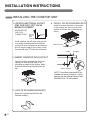
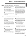
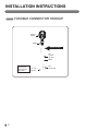
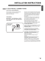
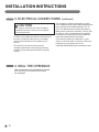
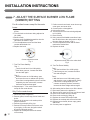
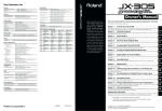
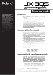
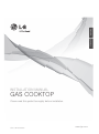
ENGL ISH
ESPA ÑOL
INSTALLATION MANUAL
GAS COOKTOP
Please read this guide thoroughly before installation.
P/No.: MFL62725502
www.lge.com
INSTALLATION INSTRUCTIONS
READ ALL INSTRUCTIONS BEFORE INSTALLATION
IN THE COMMONWEALTH OF MASSACHUSETTS
• This product must be installed by a licensed
plumber or gas fitter.
• A flexible gas connector, when used, must not
exceed 3 feet in length.
• When using ball type gas shut-off valves,
they shall be the T-handle type.
FOR YOUR SAFETY
WARNING : If the information in this
manual is not followed exactly, a fire or
explosion may result causing property
damage, personal injury or death.
-Do not store or use combustible materials,
gasoline or other flammable vapors and
liquids in the vicinity of this or any other
appliance.
WHAT TO DO IF YOU SMELL GAS
Do not try to light any appliance.
Do not touch any electrical switches,
Do not use any phone in your building.
Immediately call your gas supplier from a neighbor′s
phone. Follow the gas supplier instructions.
• If you cannot contact your gas supplier, call the
fire department.
•
•
•
•
Installation and service must be performed by
a qualified installer, service agency or the gas
supplier.
PREPARING FOR INSTALLATION
TOOLS YOU WILL NEED
MATERIALS YOU MAY NEED
• Gas line shut-off valve
• To reduce the possibility of gas leaks, apply teflon
tape or a thread compound approved for use
with LP or Natural gases to all threaded connections.
Phillips screwdriver
Flat-blade screwdriver
Pencil and ruler
Open-end or
adjustable wrench
• Flexible metal appliance connector (5/8” I.D.)
A 3-foot length is recommended for ease of
installation but other lengths are acceptable.
Never use an old connector when installing a
new cooktop.
Pipe wrench(2)
(one for support)
• Flare union adapter for connection to gas supply
line (3/4” or 1/2” NPT x 5/8” I.D.)
• Flare union adapter for connection to pressure
regulator on cooktop. (1/4” NPT x 1/2” I.D.)
MATERIALS YOU MAY NEED
• Liquid leak detector or soapy water.
Sealant
Joint
Sealant
2
Pipe Fittings
Flexible Connector
Shut Off
Valve
INSTALLATION INSTRUCTIONS
ENGL ISH
INSTALLATION SAFETY INSTRUCTIONS
BEFORE YOU BEGIN
Remove all tape and packing materials before using the cooktop. Dispose all plastic bags after
unpacking the cooktop. Never allow children to play with packing materials.
IMPORTANT SAFETY INSTRUCTIONS
Read these instructions completely and carefully. Improper installation, adjustment, alteration,
service or maintenance can cause injury or property damage.
For assistance or additional information, consult a qualified installer, service agency, manufacturer
(dealer) or your gas supplier.
Never reuse old flexible connectors. The use of old flexible connectors can cause gas leaks and
personal injury. Always use NEW flexible connectors when installing a gas appliance.
This is the safety alert symbol. This symbol alerts you to potential hazards that can kill or
hurt you and others. All safety messages will follow the safety alert symbol and either the
word “ WARNING” or “CAUTION”.
WARNING
This symbol will alert you to hazards or unsafe practices which could
cause serious bodily harm or death.
CAUTION
This symbol will alert you to hazards or unsafe practices which could
cause bodily injury or property damage.
IMPORTANT: Remove all packing material and
literature before connecting gas and electrical supply.
• Be sure the wall coverings around the cooktop can
withstand heat generated by the cooktop up to 200 °F.
• Have your cooktop installed by a qualified installer.
• Avoid placing cabinets above the cooktop.
To minimize the hazard caused by reaching over the
open flames of operating burners, install a ventilation
hood over the cooktop that projects forward at least
5” beyond the front of the cabinets.
• Your cooktop must be electrically grounded in
accordance with local codes or, in the absence of
local codes, in accordance with the National
Electrical Code (ANSI/NFPA 70, latest edition). In
Canada, electrical grounding must be in accordance
with the current CSA C22.1 Canadian Electrical
Code Part 1 and/or local codes.
Refer to 3. Electrical Connections, in this manual.
3
INSTALLATION INSTRUCTIONS
INSTALLATION SAFETY INSTRUCTIONS (continued)
• The ventilating hood must be constructed of sheet
metal not less than 0.0122” thick. Install above the
cooktop with a clearance of not less than 1/4”
between the hood and the underside of the
combustible material or metal cabinet. The hood
must be at least as wide as the appliance and
centered over the appliance. Clearance between
the cooking surface and the ventilation hood surface
MUST NEVER BE LESS THAN 24 INCHES.
EXCEPTION: Installation of a listed microwave oven
or cooking appliance over the cooktop shall conform
to the installation instructions packed with that
appliance.
• If cabinets are located above the cooktop, allow a
minimum clearance of 30” between the cooking
surface and the bottom of unprotected cabinets.
• If a 30” clearance between cooking surface and
overhead combustible material or metal cabinets
cannot be maintained, protect the underside of the
cabinets above the cooktop with not less than 1/4”
insulating millboard covered with sheet metal not
less than 0.0122” thick. Clearance between the
cooking surface and protected cabinets MUST
NEVER BE LESS THAN 24 INCHES.
4
• The vertical distance from the plane of the cooking
surface to the bottom of adjacent overhead cabinets
extending closer than 1” to the plane of the cooktop
sides must not be less than 18”. (See the
Dimensions and Clearances illustration in this
manual.)
• Do not abstruct the combustion or ventilation air.
• Leak testing of the appliance shall be conducted
according to the manufacturer’s instructions.
CAUTION:
Items of interest to children
should not be placed in cabinets above the cooktop.
- children climbing on the cooktop to reach items
could be seriously injured.
INSTALLATION INSTRUCTIONS
Provide enough clearances between the cooktop
and adjacent combustible surfaces. These dimensions
must be met for safe use of your cooktop.
The location of the electrical outlet and pipe opening
may be adjusted to meet specific requirements.
The cooktop may be placed with 2 3/4” clearance to
the back wall.
1. MAINTAIN THE FOLLOWING
MINIMUM CLEARANCE
DIMENSIONS
13˝MAX. Depth of unprotected
overhead cabinets
3. RECOMMENDED GAS SUPPLY
LOCATION FROM BACKWALL
1” Min. From Backwall
Recommended
gas supply
location
A˝ MIN. clearance from
cutout to side wall on
the right of the unit
3 3/4 MIN.
B″MIN
30˝ MIN. clearance
from countertop to
unprotected overhead
surface
A
A˝ MIN. clearance
from cutout to side
wall on the left of
unit.
C
L
18˝ MIN. height
from countertop
to nearest cabinet
on either side of
unit
A
4. MAKE SURE WALL COVERINGS,
COUNTERTOP AND CABINETS
AROUND COOKTOP CAN
WITHSTAND HEAT(UP TO 200℉)
GENERATED BY COOKTOP
2. COOKTOP AND CUTOUT
DIMENSIONS
D
C
depth
width
E
Wall covering ,
cabinets and
counterto p
must withstan d
heat up to
200°F
height
F
G
width
depth
J
H
depth cut
width cut
L
L″ MIN.
Between
cutout
and the wall
behind the
cooktop
To ensure accuracy, it is best to make
a template when cutting the opening
in the counter
K
K″ MIN.
From front
edge of cutout
and front edge
of countertop
MODEL
A
30″ Cooktop
11
13
″
16
11
13
″
16
36″ Cooktop
From Cutout
Center Line
B
C
30″
30″
36″
36″
D
2111 16″
11
21
″
16
E
3 3 4″
3
3 ″
4
F
28
1 ″
4
33
5 ″
8
G
19
3 ″
8
19
3 ″
8
J
K
L
19
11 ″
16
1
5 ″
8
2
3 ″
4
19
11 ″
16
1
5 ″
8
2 3 4″
H
28
1 ″
2
33
15
″
16
5
ENGL ISH
DIMENSIONS AND CLEARANCES
INSTALLATION INSTRUCTIONS
INSTALLING THE COOKTOP UNIT
1. LOCATE ELECTRICAL OUTLET
AND GAS SHUT-OFF VALVE
BENEATH CABINET
NEVER RE-USE
OLD FLEX
CONNECTORS.
Electrical
outlet 12˝
below
countertop
4 INSTALL THE RETAINER BRACKETS
Install the retainer brackets to the bottom
of the cooktop unit. then snug the bolts
against the bottom of the countertop as
shown
Shut-Off
valve
Install a manual shut-off valve in the gas line
in an easily accessible location outside the
cooktop. Be sure you know how and where to
shut off the gas supply to the cooktop. Install
the electrical outlet 12˝ below the countertop.
Retainer brackets
Cooktop
2. INSERT COOKTOP INTO CUTOUT
Insert the cooktop centered into the cutout
opening. Be sure the front edge of the
countertop is parallel to the cooktop. Make
final check that all required clearances are
met.
Countertop
Screw
Retainer brackets
NOTE: The retainer brackets MUST be
installed to meet local codes or, in their
absence, with the National Electrical Code
ANSI/NFPA No. 70, latest edition.
3. LOCATE RETAINER BRACKETS
Remove the retainer brackets from the
literature package.
6
INSTALLATION INSTRUCTIONS
ENGL ISH
1. PROVIDE ADEQUATE GAS SUPPLY
This cooktop is designed to operate at a pressure
of 5” of water column on natural gas or 10” of water
column on LP, propane or butane gas.
Make sure you are supplying your cooktop with the
type of gas for which it is designed.
This cooktop is convertible for use on natural or
propane gas. When using this cooktop on LP gas,
conversion must be made by a qualified LP installer
before attempting to operate the cooktop on that
gas.
For correct operation, the pressure of natural gas
supplied to the regulator should be between 5” and
13” of water column.
For LP gas, the pressure supplied must be between
10” and 13” of water column.
When checking for correct operation of the regulator,
the inlet pressure must be at least 1” more than the
operating -manifold- pressure as given above.
The pressure regulator located at the inlet of the
cooktop manifold must remain in the supply line
regardless of whether natural or LP gas is being used.
A flexible metal appliance connector used to connect
the cooktop to the gas supply line must have an
I.D. of 5/8” and can be 3 feet max. in length for easy
installation. In Canada, flexible connectors should
be single wall metal connectors less than 6 feet
in length.
2. CONNECT THE COOKTOP TO GAS
Shut off the main gas supply valve before
removing the old cooktop and leave it off until the
new hook-up has been completed. Don’t forget to
relight the pilot on other gas appliances when you
turn the gas back on.
Because hard piping restricts movement of the
cooktop, the use of a CSA International-certified
flexible metal appliance connector is recommended
unless local codes require a hard-piped connection.
Never reuse an old connector when installing a new
cooktop. If the hard piping method is used, you must
carefully align the pipe; the cooktop cannot be moved
after the connection is made.
To prevent gas leaks, put pipe joint compound on,
all male -external- pipe threads.
1 Install a manual gas line shut-off valve in the gas
line in an easily accessed location outside of the
cooktop. Be sure everyone operating the
cooktop knows where and how to shut off the
gas supply to the cooktop.
2 Install male 1/2” flare union adapter to the 1/2”
NPT internal thread at inlet of pressure regulator.
Use a backup wrench on the pressure regulator
fitting to prevent damage.
3 Install male 1/2” or 3/4” flare union adapter to the
NPT internal thread of the manual shut-off valve,
taking care to back-up the shut-off valve to keep
it from turning.
4 Connect a flexible metal connector to the adapter
on the cooktop. Position the cooktop to permit
connection at the shut-off valve.
5 When all connections have been made, be
sure all cooktop controls are in the off position
and turn on the main gas supply valve.
Check for gas leaks by using manometer.
If a manometer is not available, turn the gas supply
on to the cooktop on and use a liquid leak detector
at all joints and connections to check for leaks.
Tighten all connections, if necessary, to prevent
gas leakage in the cooktop or supply line.
WARNING!
DO NOT USE A FLAME TO CHECK FOR GAS LEAKS.
Disconnect the cooktop and its individual shut-off
valve from the gas supply piping system during any
pressure testing of that system at test pressures
more than 1/2 psig(3.5kPa).
Isolate the cooktop from the gas supply piping system
by closing its individual shut-off valve during any
pressure testing of the gas supply system at test
pressures equal to or less than 1/2 psig(3.5kPa)
7
INSTALLATION INSTRUCTIONS
FLEXIBLE CONNECTOR HOOKUP
Pressure
regulator
Adapter
Gas Flow into Range
Flex
connector
(6 ft. max. )
Adapter
Installer: Inform the
consumer of the
location of the gas
shut-off valve.
8
1/2” or 3/4”
Gas pipe
Gas
shut-off valve
INSTALLATION INSTRUCTIONS
ENGL ISH
3. ELECTRICAL CONNECTIONS
ELECTRICAL REQUIREMENTS
120 Volt, 60 Hertz, properly grounded dedicated
circuit protected by a 15 A or 20 A circuit
breaker or time delay fuse.
GROUNDING
IMPORTANT: FOR PERSONAL SAFETY,
THIS APPLIANCE MUST BE PROPERLY
GROUNDED.
PREFERRED
METHOD
The power cord of this appliance should be equipped
with a three-prong (grounding) plug which mates with
a standard three-prong grounding wall receptacle to
reduce the possibility of electric shock hazard from
this appliance.
The customer should have the wall receptacle and
circuit checked by a qualified technician to be sure
the receptacle is properly grounded.
When connecting the cord of this cooktop to a
standard two-prong wall receptacle, it is the
personal responsibility and obligation of the customer
to have it replaced with a properly grounded
three-prong wall receptacle.
DO NOT, UNDER ANY CIRCUMSTANCES, CUT OR
REMOVE THE THIRD (GROUND) PRONG FROM
THE POWER CORD.
Ensure proper ground
exists before use
A word about Ground Fault Circuit Interrupters –
Ground Fault Circuit Interrupters are not required or
recommended for gas range receptacles.
Ground Fault Circuit Interrupters are devices that
sense leakage of current in a circuit and
automatically switch off power when a threshold
leakage level is detected.
These devices must be manually reset by the
customer.
The National Electrical Code requires the use of
Ground Fault Circuit Interrupters in kitchen
receptacles installed to serve countertop surfaces.
Performance of the cooktop will not be affected if
it is operated from a Ground Fault Circuit Interrupters
protected circuit but occasional nuisance can occur.
9
INSTALLATION INSTRUCTIONS
3. ELECTRICAL CONNECTIONS
CAUTION
The customer should have the circuit checked by
a qualified technician to make sure the receptacle
is correctly grounded.
DO NOT use an adapter plug because disconnecting of
the power cord places undue strain on the adapter
and causes eventual failure of the adapter ground
terminal.
The customer must have the two-prong wall
receptacle replaced with a three-prong (grounding)
receptacle by a qualified technician before using this
cooktop.
4. SEAL THE OPENINGS
Seal any openings in the wall behind the cooktop
and in the floor of the cabinet when hookups
are completed.
10
(continued)
The installation of appliances designed for mobile
home installation should conform with the Manufactured
Home Construction and Safety Standard, Title 24
CFR, Part 3280 (formerly the Federal Standard for
Mobile Home Construction and Safety, Title 24, HUD,
Part 280) or, when such standard is not applicable,
the Standard for Manufactured Home Installations,
latest edition (Manufactured Home Sites,
Communities and Set-Ups), ANSI A225.1, latest
edition, or with local codes. In Canada, mobile home
installation must comply with the current
CAN/CSA Z240/MH Mobile Home Installation Code.
INSTALLATION INSTRUCTIONS
ENGL ISH
5. ASSEMBLE THE SURFACE BURNERS
Make sure the hole in the burner head is positioned
over the electrode.
CAUTION
DO NOT operate the burners without all parts in
place.
Hole
Place the burner caps and heads on the cooktop.
Make sure that the caps and heads are placed in the
correct locations.
Electrode
Extra large burner (Center)
head and cap
Small burner
head and cap
Medium burner
head and cap
Lrage burner
head and cap
6. CHECK IGNITION OF SURFACE BURNERS
Operation of all cooktop burners should be checked
after the COOKTOP and gas supply lines have been
carefully checked for leaks.
ELECTRIC IGNITION
Select a top burner knob, push down and then turn
counterclockwise to the “LITE” position.
You can hear a clicking sound indicating proper
operation of the spark module.
Once the air has been purged from the supply lines,
burner should ignite within 4 seconds.
After burner ignites, rotate knob out of the “LITE”
position. Try each burner in succession until all
burners have been checked.
QUALITY OF FLAMES
The combustion quality of burner flames needs to be
confirmed visually.
A Yellow flames — Call for service
B Yellow tips on outer cones
— It is normal for LP gas
C Soft blue flames
— It is normal for natural gas
If burner flames look like A, call for service.
B or C is normal burner flames, depending on the
type of gas you use.
With LP gas, some yellow tipping on outer cones is
normal.
11
INSTALLATION INSTRUCTIONS
7. ADJUST THE SURFACE BURNER LOW FLAME
(SIMMER) SETTING
For all surface burners except for the center
burner
1. Light all surface burners except for the center
burner.
2. Turn the knob on the burner being adjusted to
LO (LOW).
3. Remove knob.
4. Insert a small, flat bladed screwdriver into the
valve stem as shown in Fig.2.
5. Turn the adjustment screw until the flame
reaches the desired size.
6. Replace the knob.
Center adjustment screw
Fig. 2
7. Test The Flame Stability.
Test 1 :
Turn the knob from HI to LOW quickly.
lf the flame goes out, increase the flame
size and test again.
Test 2 :
With the burner on a LOW setting, open
and close the oven or cabinet door quickly.
If the flame is extinguished by the air currents
created by the door movement, increase
the flame height and test again.
8. Repeat steps 1 - 6 for each surface burner
except for the center burner.
Only For the center burner
12
1. Disconnect power to appliance.
2. Remove grates, burners caps, burner heads and
knobs.
3. Remove all the screws on the cooktop with a
philips screwdriver.
4. Remove the cooktop by lifting it up.
5. Remove LED lamp module of the center valve
by unclipping. In this case, the ignition switch
should be positioned properly.
6. Replace the cooktop and secure the screws
of the cooktop.
7. Position center burner head, center burner cap,
center grate, and center knob.
8. Connect power to the appliance.
9. Light center burner.
10. Turn the knob on the burner being adjusted
to LO (LOW).
11. Remove knob.
12. Using a small, flat bladed screwdriver insert
into the hole next to the valve stem to adjust
the outer flame as shown in Fig.3.
13. Turn the adjustment screw until the flame
reaches the desired size.
14. Replace the knob.
Adjustment screw next to the valve shaft
Fig. 3
15. Test The Flame Stability.
Test 1 :
Turn the knob from HI to LOW quickly.
If the flame goes out, increase the flame
size and test again.
Test 2 :
With the burner on a LOW setting, open
and close the oven or cabinet door quickly.
If the flame is extinguished by the air
currents created by the door movement,
increase the flame height and test again.
16. After setting the low flame, turn off the burner.
17. Disconnect power to the appliance.
18. Remove knob, grate, burner cap, and burner head.
19. Remove all screws from the cooktop.
20. Remove the cooktop by lifting up.
21. Replace the center LED lamp module.
22. Replace the cooktop and secure all screws.
23. Replace burner heads, burner caps, grates
and knobs.
24. Connect power to appliance.
INSTALLATION INSTRUCTIONS
ENGL ISH
WHEN ALL HOOKUPS ARE COMPLETE
Make sure all controls are left in the off position.
Make sure the flow of combustion and ventilation
air to the cooktop is unobstructed.
CONVERTING TO LP GAS
(OR CONVERTING BACK TO NATURAL GAS FROM LP)
This cooktop leaves the factory set for use with
natural gas. When converting to LP gas, the
conversion must be performed by a qualified LP
gas installer.
The conversion instructions and LP orifices are
supplied with your cooktop.
Keep these instructions and the orifices in case
you want to convert back to natural gas.
13
Memo
14
BEFORE YOU BEGIN
Read these instructions completely
and carefully.
Note to Installer:Leave these instructions with the appliance after
installation is completed.
Installation of this cooktop must conform with local codes, or in the
absence of local codes, with the National Fuel Gas Code, ANSI
Z223.1/NFPA.54, latest edition.
This cooktop has been design-certified by CSA International
according to ANSI Z21.1, latest edition and Canadian
Gas Association according to CAN/CGA-1.1 latest edition.
Note to Consumer:Keep the User’s Guide and Installation
Instructions for future reference.
NOTE: This appliance must be properly grounded.
• The electrical diagram is in an envelope attached in the burner box
of the cooktop.
• Skill level – Installation of this appliance requires basic mechanical
As with any appliance using gas and generating heat, there are
skills.
certain safety precautions you should follow. You will find these
precautions in the Important Safety Information section in your User’s • Proper installation is the responsibility of the installer..
Guide. Read them carefully.
• Product failure due to improper installation is not covered under the
Warranty.
• IMPORTANT – Save these instructions for local electrical
• Remove all tape and packaging..
inspector’s use.
• IMPORTANT
– Observe all governing codes and ordinances.
• Make sure the burners are properly seated and level..
• Take the accessory pack out of the packing.
• Check to be sure that no cooktop parts have come loose during
shipping.
To contact LG Electronics
24 hours a day, 7 days a week:
Para comunicarse con LG Electronics
24 horas al día, 7 días a la semana:
1-800-243-0000 (USA)
1-800-243-0000 (EE.UU.)
Or visit us on the Web at:
O visítenos en la Web en:
us.lge.com (USA)
us.lge.com (EE.UU.)
Printed in Korea