1
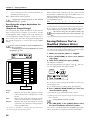
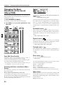
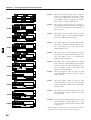
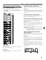
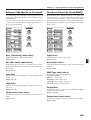
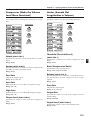
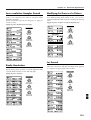
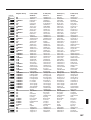
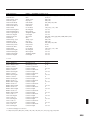
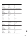
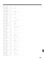
Easy Operation List
Whole
Patch Edit
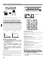
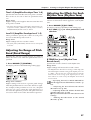
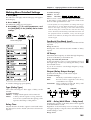
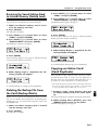
Modify value by larger steps
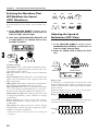
LCD Contrast
Tuning
[SHIFT] + [VALUE] (p. 16)
[EDIT] -> BANK [8] (p. 168)
[EDIT] -> BANK [8] -> PAGE [>] (p. 168)
Confirm Current Settings
Set Envelope Depth
[SHIFT] + knob (p. 55)
[ENVELOPE/LFO1/EFFECTS] + [VALUE]
when the “ENVELOPE” indicator is lit (p. 59, 64, 88, 92)
[ENVELOPE/LFO1/EFFECTS] + [VALUE]
when the “LFO1” indicator is lit (p. 72)
[FILTER/AMP/PITCH] + [VALUE]
when the “FILTER” indicator is lit (p. 61)
[FILTER/AMP/PITCH] + [VALUE]
when the “AMP” indicator is lit (p. 67)
[FILTER/AMP/PITCH] + [VALUE]
when the “PITCH” indicator is lit (p. 57)
[SHIFT] + [WRITE] in PATCH page -> Specify destination (p. 82)
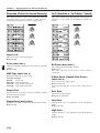
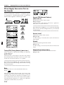
Set LFO1 Waveform
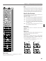
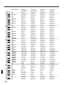
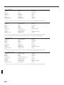
Effects
Effects On/Off (Master)
Select Multi Effects Type
[SHIFT] + [FX ON/OFF] (p. 101)
[ENVELOPE/LFO1/EFFECTS] + [VALUE]
when the “Effects” indicator is lit (p. 106)
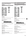
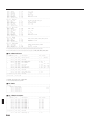
Move to the last measure
Move to the first measure
All Mute
Monitor
Mute Exchange
Quickly listen to next pattern
MIDI Update
Save Patterns
[FWD] + [BWD] (p. 31)
[BWD] + [FWD] (p. 31)
[SHIFT] + [PART MUTE] (p. 32)
[PART MUTE] + PART [1]–[R] (p. 32)
[PART MUTE] + [PART SELECT] (p. 32)
[SHIFT] + PAGE [<] [>] during Pattern playback (p. 31)
[SHIFT] + [STOP/PLAY] (p. 40)
[SHIFT] + [WRITE] in PTN page -> Specify destination (p. 36)
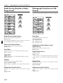
Save Patches
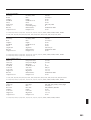
Turntable
Turntable On/Off
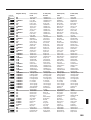
[PTN SET] + BANK, NUMBER button to be registerd (p. 152)
[SHIFT] + [WRITE] in PTN SET page -> Specify destination (p. 153)
Song
[SHIFT] + [WRITE] in SONG page -> specify destination (p. 157)
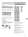
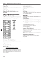
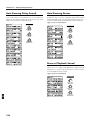
Pattern Recording
Real-Time Recording
Rehearsal
Real-Time Erase
Microscope
Change Event
Delete Event
Insert Event
Move Event
Step Recording1
Tie
Rest
Back
Step Recording2
Select Note
Edit for Input Notes
CTRL1
CTRL2
CTRL1
CTRL2
CTRL1
[REC] -> [STOP/PLAY] (p. 125)
[REC] during recording (p. 127)
[SHIFT] + [ERASE] during recording
->Data is erased while [REC] is pressed (p. 130)
[SHIFT] + [M.SCOPE] (p. 146)
PAGE[>] -> [VALUE] -> [ENTER] (p. 148)
NUMBER [2]+[ENTER] (p. 150)
NUMBER [3]+[ENTER] (p. 150)
[SHIFT] + [REC] + [VALUE] (p. 151)
[SHIFT] + [M.SCOPE] -> [REC] -> [REC] (p. 131)
[BWD] (p. 133)
[FWD] (p. 133)
[SHIFT] + [BWD] (p. 133)
[SHIFT] + [M.SCOPE] -> [REC] -> [STOP/PLAY] (p. 131)
[SHIFT] + keyboard (p. 134)
key to be edited + [VALUE] (p.136)
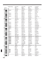
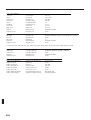
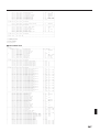
[SHIFT]+Modulation lever (p. 47)
Multi Effects Assignment
CTRL1
CTRL2
Pattern Set
Save Songs
Set Random Pan Switch
Set Coarse Tune
Pattern Play
Register Patterns
Save Pattern Set
Set Filter Type
CTRL2
CTRL1
CTRL2
CTRL1
CTRL2
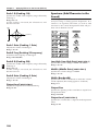
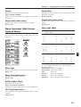
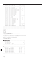
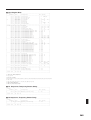
4-BAND-EQ
High Gain
Low Gain
DISTORTION
Drive
AMP Type
PHONOGRAPH
Depth
D Noise Level
TREMOLO
Depth
SPECTRUM
Low-High Gain
Middle Gain
Lo-Fi
Bit Down
S-Rate Down
COMPRESSOR
Attack
Sustain
PHASER
Depth
ENHANCER
Sens
Mix Level
NOISE
Lo-Fi Level
Noise Level
LIMITER
Threshold
Release
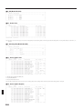
CHORUS
Depth
OVERDRIVE
Drive
AMP Type
RADIO-TUNG
Radio-Detune
Noise Level
SLICER
Timing PTN
Accent PTN
SPACE-D
Depth
Rate
TETRA-CHRS
Depth
Rate
AUTO-PAN
Depth
Rate
Rate
FLANGER
Depth
Rate
FB-P-SHIFT
Coarse
Fine
Rate
ST-FLANGER
Depth
Step Rate
REVERB
Time
Balance
Rate
SHORT-DELY
Time-L
Time-R
GATE-REVRB
Gate Time
Balance
Change Setup for RPS part
Change Patch for RPS part
Save RPS Sets
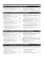
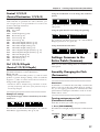
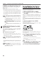
An Overview of the JX-305
This chapter explains how the JX-305's sound generator and sequencer are organized, and explains the
basic operation. By reading this chapter, you can gain an overall understanding of the JX-305.
Chapter 2
Playing the Keyboard
This chapter explains the Key Mode function, the pitch bend lever, the pedals, etc., and how to use the
arpeggiator. Be sure to read this chapter.
Chapter 3
Playing Patterns
This chapter explains how to play patterns, and how to use functions such as Real-Time Transpose, Mute,
Part Mixer, and Play Quantize. Be sure to read this chapter.
Chapter 4
One-Touch Phrase Playback (RPS)
This chapter explains the various effect types and how to use them. Read this chapter when you wish to
use effects.
Chapter 5
Creating Original Sounds (Patch Edit)
This chapter explains the parameters that modify the sound. Read this chapter so you better understand
how to use the knobs to control the sound when creating your own sounds.
Chapter 6
Creating an Original Rhythm Set (Rhythm Edit)
This chapter explains the rhythm set parameters. Read this chapter when you wish to create an original
rhythm set.
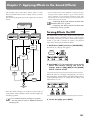
Applying Effects to the Sound (Effects)
Recording Patterns
This chapter explains how to record patterns. Read this chapter when you wish to record patterns.
Chapter 9
Editing Patterns
This chapter explains how to edit patterns, and how to modify music data after it's been recorded. Read
this chapter as necessary.
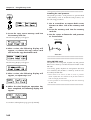
[ARP] + [VALUE] (p. 25)
[SHIFT] + [WRITE] in arpeggio setting page
->Specify destination (p. 28)
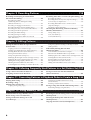
Chapter 10
Collecting Frequently Used Patterns in a Set (Pattern Set)
This chapter explains how to use Pattern Sets and how to store patterns in a set. Read this chapter when
you wish to use a pattern set.
Mute all parts except for the part to be registerd
->[RPS] + destination keyboard (p. 49)
[RPS] + [TEMPO&MEASURE]
-> Select parameter -> Select RPS part using keyboard (p. 50)
[RPS] + [PATCH] -> Select RPS part using keyboard (p. 51)
[SHIFT] + [WRITE] in RPS SET page
-> Specify destination (p. 52)
Chapter 11
Connecting Patterns in Playback Order to Create a Song
This chapter explains how to play back, record, and edit songs. Be sure to read this chapter if you wish to
use songs.
Chapter 12
Using Memory Cards
Here you can learn how to use memory cards to back up your data, and how to make copies of a card. Be
sure to read this chapter before using memory cards.
Chapter 13
[GRID/SHUFFLE/GROOVE] + [VALUE] (p. 40)
[SHIFT] + [QTZ SELECT]- > PART [1]–[R] (p. 41)
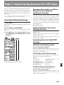
Setting the Operating Environment of the JX-305 (System)
This chapter explains settings that determine the overall configuration for your JX-305, such as its tuning
and synchronization preferences. Read this chapter as necessary.
Chapter 14
Part Mixer
Set using [INC] [DEC]
Key Shift in Octave step
Chapter 1
Chapter 8
Play Quantize
Select the Resolution/Template
Select the Part for Quantize
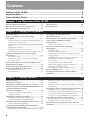
This owner's manual consists of the following 14 chapters and supplementary information.
Before you read this manual, you should read through the Quick Start manual so you're familiar with the basic operation of the unit.
This chapter explains the various effect types and how to use them. Read this chapter when you wish to
use effects.
RPS
Register RPS Set
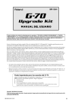
Before using this unit, carefully read the sections entitled: “USING THE UNIT
SAFELY” and “IMPORTANT NOTES” (Owner’s
Manual p. 2, 3, 9). These
sections provide important
information concerning the
proper operation of the
unit. Additionally, in order
to feel assured that you
have gained a good grasp
of every feature provided
by your new unit, Quick
Start and Owner’s Manual
should be read in its entirety. The manuals should be
saved and kept on hand as
a convenient reference.
Chapter 7
Arpeggiator
Select Style
Save Arpeggio Settings
Owner's Manual
Advanced Applications
This chapter explains how the JX-305 can be used with external MIDI equipment, and gives tips for creating sounds and performing. Read this chapter as necessary.
Select current part -> [INC] [DEC] (p. 33)
Select K-Sft -> [SHIFT] + knob (p. 34)
Supplementary Information
Consult this chapter when the JX-305 does not function as you expect, or if an error message is displayed.
This chapter also contains information such as parameter lists and the MIDI implementation.
• SmartMedia is a trademark of Toshiba corporation.
• All product names mentioned in this document are trademarks or registered trademarks of their respective owners.
01452367
'00-2-E3-31K
Copyright © 1998 ROLAND CORPORATION
All rights reserved. No part of this publication may be reproduced in any form without the written
permission of ROLAND CORPORATION.
1
2
3
4
5
6
7
8
9
10
11
12
13
14
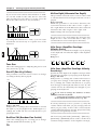
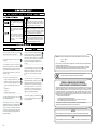
Used for instructions intended to alert
the user to the risk of death or severe
injury should the unit be used
improperly.
Used for instructions intended to alert
the user to the risk of injury or material
damage should the unit be used
improperly.
* Material damage refers
other adverse effects
respect to the home
furnishings, as well
animals or pets.
to damage or
caused with
and all its
to domestic
• Before using this unit, make sure to read the
instructions below, and the Owner's Manual.
.........................................................................................................
• Do not open (or modify in any way) the unit or its
AC adaptor.
.........................................................................................................
• Do not attempt to repair the unit, or replace parts
within it (except when this manual provides specific
instructions directing you to do so). Refer all servicing
to your retailer, the nearest Roland Service Center, or
an authorized Roland distributor, as listed on the
"Information" page.
.........................................................................................................
• Never use or store the unit in places that are:
• Subject to temperature extremes (e.g., direct
sunlight in an enclosed vehicle, near a heating
duct, on top of heat-generating equipment); or are
• Damp (e.g., baths, washrooms, on wet floors); or
are
• Humid; or are
• Dusty; or are
• Subject to high levels of vibration.
.........................................................................................................
• This unit should be used only with a rack or stand
that is recommended by Roland.
.........................................................................................................
• When using the unit with a rack or stand recommended by Roland, the rack or stand must be carefully placed so it is level and sure to remain stable. If not
using a rack or stand, you still need to make sure that
any location you choose for placing the unit provides
a level surface that will properly support the unit, and
keep it from wobbling.
The
symbol alerts the user to important instructions
or warnings.The specific meaning of the symbol is
determined by the design contained within the
triangle. In the case of the symbol at left, it is used for
general cautions, warnings, or alerts to danger.
The
symbol alerts the user to items that must never
be carried out (are forbidden). The specific thing that
must not be done is indicated by the design contained
within the circle. In the case of the symbol at left, it
means that the unit must never be disassembled.
The ● symbol alerts the user to things that must be
carried out. The specific thing that must be done is
indicated by the design contained within the circle. In
the case of the symbol at left, it means that the powercord plug must be unplugged from the outlet.
• Be sure to use only the AC adaptor supplied with
the unit. Also, make sure the line voltage at the installation matches the input voltage specified on the AC
adaptor's body. Other AC adaptors may use a different polarity, or be designed for a different voltage, so
their use could result in damage, malfunction, or electric shock.
.........................................................................................................
• Avoid damaging the power cord. Do not bend it
excessively, step on it, place heavy objects on it, etc. A
damaged cord can easily become a shock or fire hazard. Never use a power cord after it has been damaged.
.........................................................................................................
• This unit, either alone or in combination with an
amplifier and headphones or speakers, may be capable of producing sound levels that could cause permanent hearing loss. Do not operate for a long period of
time at a high volume level, or at a level that is
uncomfortable. If you experience any hearing loss or
ringing in the ears, you should immediately stop
using the unit, and consult an audiologist.
.........................................................................................................
• Do not allow any objects (e.g., flammable material,
coins, pins); or liquids of any kind (water, soft drinks,
etc.) to penetrate the unit.
For the U.K.
IMPORTANT: THE WIRES IN THIS MAINS LEAD ARE COLOURED IN ACCORDANCE WITH THE FOLLOWING CODE.
BLUE:
NEUTRAL
BROWN: LIVE
As the colours of the wires in the mains lead of this apparatus may not correspond with the coloured markings identifying
the terminals in your plug, proceed as follows:
The wire which is coloured BLUE must be connected to the terminal which is marked with the letter N or coloured BLACK.
The wire which is coloured BROWN must be connected to the terminal which is marked with the letter L or coloured RED.
Under no circumstances must either of the above wires be connected to the earth terminal of a three pin plug.
For EU Countries
This product complies with the requirements of European Directive 89/336/EEC.
For the USA
FEDERAL COMMUNICATIONS COMMISSION
RADIO FREQUENCY INTERFERENCE STATEMENT
This equipment has been tested and found to comply with the limits for a Class B digital device, pursuant to Part 15 of the
FCC Rules. These limits are designed to provide reasonable protection against harmful interference in a residential
installation. This equipment generates, uses, and can radiate radio frequency energy and, if not installed and used in
accordance with the instructions, may cause harmful interference to radio communications. However, there is no guarantee
that interference will not occur in a particular installation. If this equipment does cause harmful interference to radio or
television reception, which can be determined by turning the equipment off and on, the user is encouraged to try to correct the
interference by one or more of the following measures:
– Reorient or relocate the receiving antenna.
– Increase the separation between the equipment and receiver.
– Connect the equipment into an outlet on a circuit different from that to which the receiver is connected.
– Consult the dealer or an experienced radio/TV technician for help.
Unauthorized changes or modification to this system can void the users authority to operate this equipment.
This equipment requires shielded interface cables in order to meet FCC class B Limit.
For Canada
NOTICE
This Class B digital apparatus meets all requirements of the Canadian Interference-Causing Equipment Regulations.
AVIS
Cet appareil numérique de la classe B respecte toutes les exigences du Règlement sur le matériel brouilleur du Canada.
2
• Immediately turn the power off, remove the AC
adaptor from the outlet, and request servicing by your
retailer, the nearest Roland Service Center, or an
authorized Roland distributor, as listed on the
"Information" page when:
• The AC adaptor or the power-supply cord has
been damaged; or
• Objects have fallen into, or liquid has been
spilled onto the unit; or
• The unit has been exposed to rain (or otherwise
has become wet); or
• The unit does not appear to operate normally or
exhibits a marked change in performance.
.........................................................................................................
• In households with small children, an adult should
provide supervision until the child is capable of following all the rules essential for the safe operation of
the unit.
.........................................................................................................
• Protect the unit from strong impact.
(Do not drop it!)
.........................................................................................................
• Do not force the unit's power-supply cord to share
an outlet with an unreasonable number of other
devices. Be especially careful when using extension
cords—the total power used by all devices you have
connected to the extension cord's outlet must never
exceed the power rating (watts/amperes) for the
extension cord. Excessive loads can cause the insulation on the cord to heat up and eventually melt
through.
.........................................................................................................
• Before using the unit in a foreign country, consult
with your retailer, the nearest Roland Service Center,
or an authorized Roland distributor, as listed on the
"Information" page.
.........................................................................................................
• The unit and the AC adaptor should be located so
their location or position does not interfere with their
proper ventilation.
.........................................................................................................
• Always grasp only the plug or the body of the AC
adaptor when plugging into, or unplugging from, an
outlet or this unit.
.........................................................................................................
• Whenever the unit is to remain unused for an
extended period of time, disconnect the AC adaptor.
.........................................................................................................
• Try to prevent cords and cables from becoming
entangled. Also, all cords and cables should be placed
so they are out of the reach of children.
.........................................................................................................
• Never climb on top of, nor place heavy objects on
the unit.
.........................................................................................................
• Never handle the AC adaptor body, or its plugs,
with wet hands when plugging into, or unplugging
from, an outlet or this unit.
.........................................................................................................
• Before moving the unit, disconnect the AC adaptor
and all cords coming from external devices.
.........................................................................................................
• Before cleaning the unit, turn off the power and
unplug the AC adaptor from the outlet (Quick Start,
p. 5).
.........................................................................................................
• Whenever you suspect the possibility of lightning in
your area, disconnect the AC adaptor from the outlet.
3
Contents
Features of the JX-305 .......................................................................................8
Important Notes.................................................................................................9
Front and Rear Panels ......................................................................................10
Chapter 1. an Overview of the JX-305 ...........................................13
How the JX-305 Is Organized ........................................13
How the Sound Generator Is Organized ....................13
How the Sequencer Is Organized.................................14
About Memory.................................................................15
Basic Operation................................................................16
Chapter 2. Playing the Keyboard ...................................................18
Selecting a Patch ..............................................................18
Playing Two Patches from the Keyboard
(Key Mode) .......................................................................18
Playing One Patch Over the Entire Keyboard (Single)....18
Layering Two Patches (Dual) ..............................................19
Playing Different Patches with the Left and Right Hands
(Split).......................................................................................19
Changing the Split Point ......................................................20
Selecting the Upper Part/Lower Part ................................20
Modifying the Key Mode Settings in the Editing Pages 20
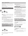
Smoothly Changing the Pitch of the Sound
(Portamento) .....................................................................21
Portamento On/Off ..............................................................21
Changing the Time Over Which the Pitch Changes
(Portamento Time) ................................................................21
Playing Notes Which Lie Outside the Range of the
Keyboard (Octave Shift).................................................21
Changing the Pitch (Pitch Bend Lever) .......................22
Applying Modulation to the Sound ............................22
Using the Modulation Lever ...............................................22
Using Aftertouch...................................................................22
Changing the Keyboard Dynamics
(Keyboard Velocity) ........................................................22
Sustaining the Notes You Play (Hold Pedal) .............23
Using a Pedal to Modify the Sound
(Control Pedal) .................................................................23
Control Pedal Settings ..........................................................23
Pressing Chords to Produce Arpeggios
(Arpeggiator) ....................................................................24
Playing Arpeggios.................................................................24
Creating an Arpeggio Pattern .............................................24
Changing the Way in Which the Arpeggio Will Play
(Arpeggio Style) ....................................................................25
Adding Expression to the Arpeggio (Accent Rate)..........25
Changing the Pitch Range of the Arpeggio
(Octave Range) ......................................................................26
Selecting the Part in Dual Mode Which
Will Play the Arpeggio (Arpeggio Destination) ...............26
Making More Detailed Settings ..........................................26
Saving Arpeggio Settings (Arpeggio Write) .....................28
Playing a Rhythm Set .....................................................28
Listening to Sound Processed by the Effects
(Audition)..........................................................................29
Chapter 3. Playing Patterns ............................................................30
Playing Patterns ...............................................................30
Adjusting the Tempo ......................................................31
Viewing the Number of Measures in a Pattern .........31
Muting a Specific Part (Part Mute/Rhythm Mute)....32
Transposing During Playback
(Real-Time Transpose) ...................................................32
Using the VALUE Dial or [INC] [DEC] .............................32
Using the Keyboard ..............................................................33
Changing the Settings of Each Part..............................33
Using the Part Mixer Page to Make Changes ...................33
Using the Editing Pages to Make Changes .......................34
Saving Patterns You’ve Modified (Pattern Write) ....36
Copying and Initializing Settings .......................................37
Using the Knobs to Modify the Sound During
Playback (Real-Time Modify).......................................38
Modifying the Sound for an Individual Rhythm Group.39
4
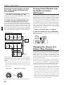
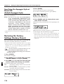
Returning a Pattern to Its Original State During Playback
(Pattern Reset)........................................................................39
Ensuring Correct Playback from the Middle of a Pattern ..
(MIDI Update) .......................................................................40
Changing the Groove of a Pattern (Play Quantize) ..40
Selecting Parts to Use with Play Quantize ........................41
Correcting Inaccuracies in the Rhythm (Grid Quantize) 41
Giving Swing to the Rhythm (Shuffle Quantize) .............42
Giving a Groove to the Rhythm (Groove Quantize)........43
Using Pedal for Control (Switch Pedal) ......................46
Specifying the Function of the Switch Pedal.....................46
Using the Pedal to Change the Tempo ..............................46
Simultaneously Changing the Tempo and Pitch
(Turntable) ........................................................................47
Chapter 4. One-Touch Phrase Playback (RPS)..................................48
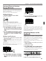
Pressing Notes to Play Back Phrases ...........................48
Making Settings for Each Phrase .................................50
Causing a Phrase to Continue Playing (RPS Hold)..........49
Using the Part Mixer to Modify Settings ...........................50
Changing the Patch of Each RPS Part ................................51
Assigning Phrases to the Keyboard .............................49
Saving the Phrases You Assigned (RPS Set Write)...52
Chapter 5. Creating Original Sounds (Patch Edit).............................53
The Basis for the Sound of a Patch (Tones)................53
Making More Detailed Settings ..........................................68
What a Tone Consists of.......................................................53
Applying Cyclic Changes to the Sound (LFO) ..........71
Sound-Editing Procedure...............................................53
Changing the Basic Waveform of the Sound
(Wave/FXM) ......................................................................56
Pitch-Related Settings ....................................................57
Selecting the Waveform That Will Modulate the Sound
(LFO1 Waveform) .................................................................72
Adjusting the Speed of Modulation (LFO1 Rate).............72
Adjusting the Depth of Modulation (LFO1 Depth) .........73
Making More Detailed Settings ..........................................74
Modifying the Pitch (Pitch)..................................................57
Making the Pitch Change Over Time (Pitch Envelope) ..58
Making More Detailed Settings ..........................................59
Brightness-Related Settings (Filter).............................61
Modifying the Brightness of the Sound (Filter) ................61
Making the Brightness Change Over Time
(Filter Envelope) ....................................................................63
Making More Detailed Settings ..........................................65
Settings Related to Volume and Pan (Amplifier) .....67
Adjusting the Volume and Pan...........................................67
Creating Time-Variable Change in Volume
(Amplifier Envelope) ............................................................68
Specifying the Parameters That Will Be Modified
by Each Controller (Control) .........................................76
Adjusting the Range of Pitch Bend (Bend Range)............76
Control 1/2/3/4 (Control Destination 1/2/3/4).............77
Ctrl 1/2/3/4 Depth (Control 1/2/3/4 Depth).................77
Settings Common to the Entire Patch (Common) .....77
Smoothly Changing the Pitch (Portamento) .....................77
Making More Detailed Settings ..........................................78
Saving Patches You’ve Created (Patch Write)............82
Copying and Initializing Settings .......................................83
Chapter 6. Creating an Original Rhythm Set (Rhythm Edit) ..............85
How a Rhythm Tone Is Organized ..............................85
Creating the Sounds........................................................85
Specifying the Basic Waveform of the Sound
(Wave) ................................................................................86
Pitch-Related Settings ....................................................87
Changing the Pitch of the Sound (Pitch) ...........................87
Making the Pitch Change Over Time (Pitch Envelope) ..87
Making More Detailed Settings ..........................................89
Brightness-Related Settings (Filter).............................90
Modifying the Brightness of the Sound (Filter) ................90
Making the Brightness Change Over Time
(Filter Envelope) ....................................................................91
Making More Detailed Settings ..........................................92
Settings Related to Volume and Pan (Amplifier) .....94
Adjusting the Volume and Pan (Amplifier)......................94
Creating Time-Varying Change in Volume
(Amplifier Envelope) ............................................................95
Making More Detailed Settings ..........................................96
Adjusting the Range of Pitch Bend (Bend Range)....97
Adjusting the Effects for Each Rhythm Tone (Rhythm
Tone) ..................................................................................97
Saving Rhythm Sets You’ve Created
(Rhythm Set Write) .........................................................98
Copying and Initializing Settings .......................................99
Chapter 7. Applying Effects to the Sound (Effects) .........................101
Turning Effects On/Off ................................................101
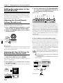
Adding Reverberation to the Sound (Reverb) .........102
Adjusting the Overall Reverb Volume (Reverb Level)..102
Adjusting the Reverb Volume for Each Part
(Part Reverb Level) .............................................................102
Making More Detailed Settings ........................................103
Adding an Echo to the Sound (Delay).......................103
Adjusting the Overall Delay Volume (Delay Level) ......104
Adjusting the Delay Volume for Each Part
(Part Delay Level) ...............................................................104
Making More Detailed Settings ........................................105
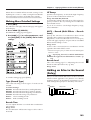
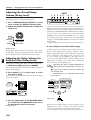
Applying Various Effects to the Sound (Multi-Effects)
106
Selecting the Type (Multi-Effects Type)...........................106
Adjusting the Overall Multi-Effects Volume
(Multi-Effects Output Level) .............................................106
Making Multi-Effects Settings...........................................107
Specifying the Part(s) to Which Multi-Effects Will Be
Applied (Part Multi-Effects Switch) .................................124
5
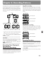
Chapter 8. Recording Patterns ......................................................125
Recording Your Playing As You Perform
(Real-Time Recording) .................................................125
Recording Procedure ..........................................................125
Auditioning Phrases During Recording
(Rehearsal Function) ...........................................................127
Recording an Arpeggio Performance...............................127
Recording Knob Movements (Modify Data)...................128
Recording Smoothly Across Pattern Boundaries ...........128
Recording Part Mixer Operations.....................................128
Recording the Mute Settings .............................................129
Recording Changes in Tempo ...........................................129
Erasing Unwanted Data While You Record
(Real-Time Erase) ................................................................130
Recording Notes One at a Time (Step Recording) ..131
Recording Procedure ..........................................................131
Recording Notes One by One (Step Recording 1) ..........132
Various Ways to Input Notes ............................................133
Recording Individual Notes to Grid Locations
(Step Recording 2)...............................................................134
Inputting Complex Rhythms.............................................136
Checking the Remaining Amount of Memory
(Memory Information)..................................................137
Temp (Temporary)..............................................................137
User (User Memory) ...........................................................137
Card (Card Memory) ..........................................................137
Chapter 9. Editing Patterns ...........................................................138
Editing the Musical Data of a Specified Part
(Pattern Edit)...................................................................138
Using Play Quantize Settings to Modify a Pattern
(Edit Quantize) ....................................................................146
Copying a Portion of a Pattern (Copy) ............................138
Deleting Unwanted Measures (Delete Measure) ...........140
Inserting Blank Measures (Insert Measure) ....................140
Erasing Unwanted Data (Erase)........................................141
Transposing the Pitch (Transpose) ...................................142
Modifying the Strength of Notes (Change Velocity) .....142
Modifying the Note Length (Change Gate Time) ..........143
Shifting the Timing Slightly (Shift Clock) .......................144
Thinning Out Unneeded Data (Data Thin) .....................145
Converting the Note Timing of a Pattern (Reclock).......145
Individually Editing Musical Data
(Microscope Edit)...........................................................146
View the Musical Data That You Input ...........................147
Musical Data Handled in Microscope Mode ..................147
Modifying the Value of Musical Data (Change Event) .148
Deleting Musical Data (Delete Event)..............................150
Inserting Musical Data (Insert Event) ..............................150
Moving Musical Data (Move Event) ................................151
Hiding Unwanted Musical Data (View Filter) ...............151
Chapter 10. Collecting Frequently Used Patterns in a Set (Pattern Set) 152
Using a Pattern Set to Recall Patterns .......................152
Assigning a Pattern to be Recalled ............................152
Saving a Pattern Set That Was Modified
(Pattern Set Write) .........................................................153
Chapter 11. Connecting Patterns in Playback Order to Create a Song.154
Playing Back a Song......................................................154
Recording a Song...........................................................155
Editing Songs (Song Edit)............................................155
Deleting Unwanted Patterns from a Song
(Delete Pattern)....................................................................156
Inserting a Pattern (Insert Pattern) ...................................157
Copying a Song (Song Copy) ............................................156
Saving a Song That You Recorded (Song Write).....157
Initializing Settings (Song Initialize) ................................158
Chapter 12. Using Memory Cards .................................................159
Cautions When Using a Memory Card .....................159
Before Using a New Card (Format) ............................159
Saving All Internal Settings to a Card
(User Backup) .................................................................160
6
Restoring the Saved Settings Back to Internal Memory
(Backup Load) ................................................................161
Deleting the Backup File from the Card
(Backup Delete)..............................................................161
Copying an Entire Card (Card Duplicate) ................161
Chapter 13. Setting the Operating Environment of the JX-305 (System).163
Controller-Related Settings .........................................163
Changing the Loudness of Notes Played on the Keyboard
(Keyboard Velocity)............................................................163
Setting Aftertouch Sensitivity (Aftertouch Sens) ...........163
Specifying How the Pedal Will Function ........................163
MIDI-Related Settings .................................................164
Disconnecting the Keyboard from the Internal Sound
Generator (Local Switch) ...................................................165
Using an External MIDI Keyboard in Place of the
Keyboard of the JX-305 (Remote Keyboard Switch) ......165
Differentiating Between Units of the Identical Model
(Device ID Number) ...........................................................165
Re-Transmitting Messages Received at MIDI IN from
MIDI OUT (Thru Function) ...............................................165
Specifying the Reception Status for Each Part
(Rx Switch) ...........................................................................165
Specifying How Knob Data Is Transmitted
(Edit Transmit/Receive Mode) .........................................165
Reception Settings for Each Type of Message ................166
Transmission Settings for Each Type of Message ..........166
Sequencer-Related Settings.........................................166
Synchronization Settings (Sync Mode) ............................167
Transmitting Synchronization Messages (Sync Out).....167
Making Songs Play Continuously (Loop Mode) ............167
Setting the Metronome (Metronome Mode) ...................167
Adjusting the Metronome Volume
(Metronome Level) .............................................................167
Specifying the Timing for RPS Playback
(RPS Trigger Quantize) ......................................................167
Synchronizing Arpeggios to the Pattern
(Arpeggio Sync)...................................................................168
Calculating a Checksum Automatically
(Auto Checksum) ................................................................168
Specifying the Resolution of the Tap Tempo
(Tap Resolution) ..................................................................168
Tuning and Sound Generator Related Settings ......168
Adjusting the Display Contrast (LCD Contrast) ............168
Adjusting the Overall Tuning (Master Tune) .................168
Tuning Each Note (Scale Tune).........................................168
Specifying How Patches Will Be Switched
(Patch Remain) ....................................................................169
Specifying the Number of Notes for Each Part
(Voice Reserve) ....................................................................169
Specifying the Variable Range of Resonance
(Resonance Limiter) ............................................................169
Specifying the Pattern at Power-On (Default Pattern) ..169
Specifying the Arpeggio Style at Power-On
(Default Arpeggio Style) ....................................................170
Restoring the Factory Settings (Factory Preset) .......170
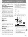
Chapter 14. Advanced Applications ..............................................171
Taking Advantage of MIDI .........................................171
What Is MIDI?......................................................................171
Controlling the JX-305 from an External MIDI Device..172
Controlling an External MIDI Device from the JX-305..174
Synchronizing an External Sequencer..............................175
Synchronizing to an External Sequencer .........................175
Saving Pattern and Patch Data on an External Sequencer
(Bulk Dump) ........................................................................176
Example of Real-Time Modify....................................178
Example of Multi-Effects Settings .............................180
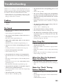
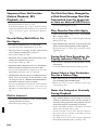
Troubleshooting .............................................................................................183
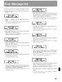
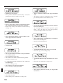
Error Meggage List .........................................................................................185
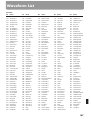
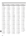
Waveform List................................................................................................187
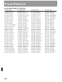
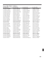
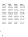
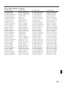
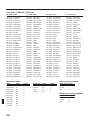
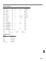
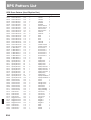
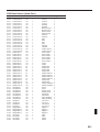
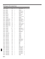
Preset Patch List .............................................................................................190
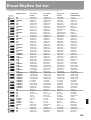
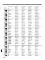
Preset Rhythm Set List ....................................................................................195
Effects Template List .......................................................................................203
Preset Pattern List ..........................................................................................204
RPS Pattern List ..............................................................................................210
RPS Set List ....................................................................................................219
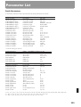
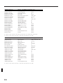
Parameter List................................................................................................223
Transmit/Receive Setting List ..........................................................................235
MIDI Implementation......................................................................................236
Main Specifications ........................................................................................256
Index .............................................................................................................257
7
Features of the JX-305
High-performance synthesis engine
The all-important sound generator is a high-performance synthesizer offering 64-note polyphony. A rich
array of parameters, including sharp filters and ADSR
envelopes can be modified using the knobs on the
panel to create your own sounds. The sound generator
can also be used as a multitimbral sound module, providing up to eight parts.
Cutting-edge patterns that lead the
scene
The JX-305 contains 274 high-quality preset patterns
for immediate use and 494 RPS patterns. Since the patterns cover a wide range, from techno to reggae, this
instrument provides everything you need for most situations.
Sounds that match today’s trends
The diverse assortment of carefully selected sounds
and rhythm sets ranges from those from the TB-303,
JUNO, JUPITER and TR-808/909—indispensable for
the dance scene—to realistic acoustic sounds. From the
day you take the JX-305 home, you can enjoy today’s
leading-edge sounds.
You can also create your own original sounds and
store them in memory for immediate recall at any
time.
Three sophisticated digital effect units
High-performance DSP (digital signal processing)
technology provides you with a wide range of effects.
Three effect units are provided: Reverb adds reverberation, Delay adds echo-like effects, and general-purpose ffect unit provides 24 types of effect that have
been optimized for dance music.
Three key modes
The JX-305 provides three key modes: single, dual,
and split. It’s easy to divide the keyboard into left and
right zones, which can play different sounds simultaneously, or you can layer two sounds for every note.
8
A sequencer to help your ideas take
shape
You can construct a song in real time as you play, simply by switching the playback patterns. During
recording, you can switch the recording part to record
non-stop.
The JX-305’s internal memory by itself can contain
approximately 75,000 notes (up to 200 patterns). By
using a memory card (SmartMedia), the capacity can
be boosted to a maximum of approximately 480,000
notes (up to 200 patterns).
Use the arpeggiator to create phrases
You can play arpeggios simply by pressing the keyboard. Your musical imagination and taste are all you
need to create completely new phrases.
RPS (Real-Time Phrase Sequence) function
You can play back phrases simply by pressing a single
key. This has a wide variety of uses, such as adding
accents during a song, or playing an entire song using
just RPS.
Play quantize changes the groove in
real time
The JX-305 provides three types of play quantize:
Grid, Shuffle and Groove. Simply by rotating a knob,
you can produce your own “groove” in real time.
Controls for live performance
The JX-305 is designed for live performance, with features such as a mute button that lets you instantly
silence the playback of a specific part or rhythm
instrument, and a Real-Time Transpose function that
lets you transpose during pattern playback. Of course,
you can also move knobs during pattern playback to
modify the sound in real time.
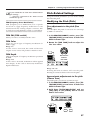
Important Notes
In addition to the items listed under “USING THE
UNIT SAFELY” on page 2, please read and observe
the following:
Power Supply
• Do not use this unit on the same power circuit with any
device that will generate line noise (such as an electric
motor or variable lighting system).
• The AC adaptor will begin to generate heat after long
hours of consecutive use. This is normal, and is not a
cause for concern.
• Before connecting this unit to other devices, turn off the
power to all units. This will help prevent malfunctions
and/or damage to speakers or other devices.
Placement
• Using the unit near power amplifiers (or other equipment
containing large power transformers) may induce hum.
To alleviate the problem, change the orientation of this
unit; or move it farther away from the source of interference.
• This device may interfere with radio and television reception. Do not use this device in the vicinity of such
receivers.
• Do not expose the unit to direct sunlight, place it near
devices that radiate heat, leave it inside an enclosed vehicle, or otherwise subject it to temperature extremes.
Excessive heat can deform or discolor the unit.
Maintenance
• For everyday cleaning wipe the unit with a soft, dry cloth
or one that has been slightly dampened with water. To
remove stubborn dirt, use a cloth impregnated with a
mild, non-abrasive detergent. Afterwards, be sure to wipe
the unit thoroughly with a soft, dry cloth.
• Never use benzine, thinners, alcohol or solvents of any
kind, to avoid the possibility of discoloration and/or
deformation.
Repairs and Data
• Please be aware that all data contained in the unit’s memory may be lost when the unit is sent for repairs.
Important data should always be backed up on a memory
card, another MIDI device (e.g., a sequencer), or written
down on paper (when possible). During repairs, due care
is taken to avoid the loss of data. However, in certain
cases (such as when circuitry related to memory itself is
out of order), we regret that it may not be possible to
restore the data, and Roland assumes no liability concerning such loss of data.
Additional Precautions
• Please be aware that the contents of memory can be irretrievably lost as a result of a malfunction, or the improper
operation of the unit. To protect yourself against the risk
of loosing important data, we recommend that you periodically save a backup copy of important data you have
stored in the unit’s memory on a memory card or another
MIDI device (e.g., a sequencer).
• Unfortunately, it may be impossible to restore the contents of data that was stored in the unit’s memory, a
memory card or another MIDI device (e.g., a sequencer)
once it has been lost. Roland Corporation assumes no liability concerning such loss of data.
• Use a reasonable amount of care when using the unit’s
buttons, sliders, or other controls; and when using its
jacks and connectors. Rough handling can lead to malfunctions.
• Never strike or apply strong pressure to the display.
• When connecting/disconnecting all cables, grasp the connector itself—never pull on the cable. This way you will
avoid causing shorts, or damage to the cable’s internal
elements.
• To avoid disturbing your neighbors, try to keep the unit’s
volume at reasonable levels. You may prefer to use headphones, so you do not need to be concerned about those
around you (especially when it is late at night).
• When you need to transport the unit, package it in the
box (including padding) that it came in, if possible.
Otherwise, you will need to use equivalent packaging
materials.
• Use only the specified expression pedal (EV-5; sold separately). By connecting any other expression pedals, you
risk causing malfunction and/or damage to the unit.
●●●●●●●●●●●●●●●●●●●●●●●●●●●●●●●●●●●●●●●●●●●●●●●●●●●●●●●●●●●●●●●●●●●●●●●●●●●●●●●●●●●●●●●●●●●●●●●●●●●●
The sounds, phrases and patterns contained in this product
are sound recordings protected by copyright. Roland hereby
grants to purchasers of this product the permission to utilize
the sound recordings contained in this product for the creation and recording of original musical works; provided
however, the sound recordings contained in this product
may not be sampled, downloaded or otherwise re-recorded,
in whole or in part, for any other purpose, including but not
limited to the transmission of all or any part of the sound
recordings via the internet or other digital or analog means
of transmission, and/or the manufacture, for sale or otherwise, of any collection of sampled sounds, phrases or patterns, on CD-ROM or equivalent means.
The sound recordings contained in this product are the original works of Roland Corporation. Roland is not responsible
for the use of the sound recordings contained in this product, and assumes no liability for any infringement of any
copyright of any third party arising out of use of the sounds,
phrases and patterns in this product.
Important
Please observe the following points when using the JX-305.
Various types of data required for the JX-305's operation are
held in internal flash memory. If the power is turned off
while data is being written to flash memory, writing will not
be completed correctly, and subsequent operation can be
affected.
While the following display appears, never turn off the
power or remove the memory card.
●●●●●●●●●●●●●●●●●●●●●●●●●●●●●●●●●●●●●●●●●●●●●●●●●●●●●●●●●●●●●●●●●●●●●●●●●●●●●●●●●●●●●●●●●●●●●●●●●●●●
9
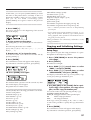
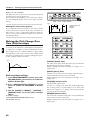
Front and Rear Panels
1
POWER
DC IN
(9V)
HOLD
CONTROL SWITCH
PEDAL
IN
OUT
MIDI
MEMORY CARD
QUANTIZE
MAX
ENVELOPE
SUSTAIN
RELEASE
RATE
FADE TIME
PITCH DEPTH
FILTER DEPTH
AMP DEPTH
AMP
LEVEL
PANPOT
SHUFFLE
REVERB LEVEL
ATTACK
DELAY LEVEL
MULTI CTRL1
MULTI CTRL 2
MULTI CTRL 3
PITCH
PORTA TIME
FINE TUNE
GROOVE
LFO 1
EFFECTS
DECAY
ARP
HOLD
DEPTH
KEYBOARD
ARPEGGIATOR / RPS
ACCENT
RATE
RPS
PORTAMENTO
SPLIT
DUAL
FILTER
CUTOFF
RESONANCE
TRANSPOSE
GRID
TIMING
VELOCITY
SEQUENCER
STOP/PLAY
OCTAVE
REC
BWD/ TIE FWD/ REST
PATTERN
SONG
M.SCOPE
4
RPS STOP
5
RPS
6
1
3
BENDER
18
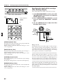
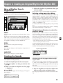
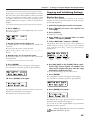
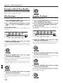
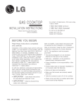
Front Panel
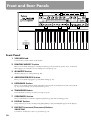
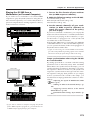
1 VOLUME Knob
Controls the overall volume of the JX-305.
2 REALTIME MODIFY Section
Here you can make settings for sound parameters (p. 54) and effects (p. 101). Also, in the Part
Mixer page you can make various settings for each part (p. 33).
3 QUANTIZE Section
Modifies the groove of the pattern (p. 40).
4 ARPEGGIATOR/RPS Section
Here you can make arpeggiator (p. 24)/RPS settings (p. 48).
5 KEYBOARD Section
Here you can make settings which affect the notes played on the keyboard, such as Key Mode
(p. 18), Octave Shift (p. 21), and Portamento (p. 21).
6 TRANSPOSE Button
Press this button when you wish to transpose (p. 32).
7 SEQUENCER Section
Here are the buttons related to sequencer playback (p. 30) and recording (p. 125).
8 DISPLAY Section
The parameter you wish to modify using [INC] [DEC] or the [VALUE] dial appears in the display.
Use these to modify the value of a parameter (p. 16).
AUDITIO
7
2
MODULATION
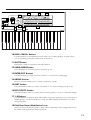
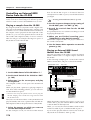
9 INC/DEC (Increment/Decrement) Buttons
VALUE Dial
MODE
PATC
OCTAVE
RANGE
10
3
THRU
REALTIME MODIFY
VOLUME
MIN
2
PHONES L ( MONO)
R
OUTPUT
4
5
6
7
10
VALUE
14
15
16
GROUP
PART
EDIT/UTILITY
PRESET
PAGE
PREV
USER
PART
SELECT
NEXT
PART
MUTE
MUTE
CTRL
EDIT
UTILITY
CARD
SPLAY
RPS
SET
UPPER
SHIFT
UNDO
/ REDO
9
BEAT
TN /
ONG
LOWER
DEC
TEMPO &
MEASURE
QTZ SELECT
BANK
ERASE
INC
EXIT
ENTER
DEMO
8
EP REC
9
10
11
12
11
13
14
1
2
2
3
3
4
4
5
5
6
6
7
7
WRITE
8
R
S E T U P
KEYBOARD
EFFECTS
PART
ARPEGGIO
CONTROLLER
MIDI
SEQUENCER
SETUP
TONE SWITCH
1
2
3
4
1
2
3
4
NUMBER
13
MIXER
1
FX ON /OFF
1
BD
2
SD
3
HH
4
CLP
5
CYM
6
TOM/PERC
7
HIT
8
OTHERS
PTN / SONG
COPY
DELETE
INSERT
ERASE
TRANSPOSE
CHG EVENT
QUANTIZE
VIEW FILTER
P A T C H
COMMON
WAVE
PITCH
FILTER
AMPLIFIER
LFO
CONTROL
RHY TONE
12
15
PART
SYSTEM
TONE SELECT
RHYTHM
PAT TERN
17
16
10 PAGE</PAGE> Buttons
Use these buttons to switch between levels of the various setting displays. In pages where
you are assigning a name, these buttons move the cursor.
11 SHIFT Button
This button is used in conjunction with other buttons.
12 UNDO/REDO Button
Press this button to cancel the previous operation (p. 17).
13 ENTER/EXIT Buttons
Use these buttons to execute/cancel an operation, or to exit from a setting page.
14 GROUP Section
Here you can select the group for sounds or patterns (p. 18, 30).
15 PART Section
Press these buttons when you wish to use buttons 1– 8 to select or mute parts (p. 18, 32).
16 EDIT/UTILITY Section
Press these buttons when you wish to edit a sound or pattern, or to store or initialize settings.
17 1–8 Buttons
Use these buttons to select the bank and number of a patch or pattern (p. 18), to select parts or
rhythm groups, or to switch muting on/off (p. 32). When editing, these buttons are used to
select parameters.
18 Pitch Bend Lever/Modulation Lever
This lever lets you modify the pitch or apply vibrato. Depending on the settings, this can also
be used to control specific parameters (p. 22, 47).
11
1
2
MEMORY
CARD
THRU
MIDI
OUT
3 4 5
IN
PEDAL
SWITCH CONTROL
HOLD
6
OUTPUT
L(MONO)
R
7 8
DC IN 9V
450mA
9
POWER
PHONES
USE ROLAND
ACI,ACB
ADAPTOR ONLY
S2M-5/S4M-5
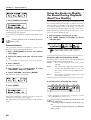
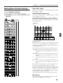
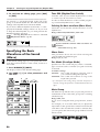
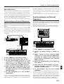
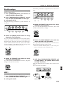
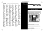
Rear panel
1 MEMORY CARD Slot
An optional memory card (SmartMedia) can be inserted here (p. 159).
2 MIDI IN/OUT/THRU Connectors
External MIDI devices can be connected here (p. 171). Use MIDI cables (sold separately) to
make connections.
3 SWITCH PEDAL Jack
A separately sold pedal switch or foot switch can be connected here. The pedal can be operated to apply various effects (p. 46).
4 CONTROL PEDAL Jack
The expression pedal (EV-5; sold separately) can be connected here. The pedal can be operated to adjust the volume or to make the sound change in various ways (p. 23).
5 HOLD PEDAL Jack
A separately sold pedal switch can be connected here. The pedal can be used to sustain notes
(p. 23).
6 OUTPUT Jacks (L (MONO), R)
An amp or mixer can be connected to these jacks. If outputting in mono, make connections to
the L jack (Quick Start, p. 3).
7 PHONES Jack
Accepts connection of headphones. Audio signals will still be output from the output jacks
even if headphones are connected (Quick Start, p. 3).
8 DC IN Jack
Connect the included AC adapter here (Quick Start, p. 3).
9 POWER Switch
This switch turns the power on/off (Quick Start, p. 5).
12
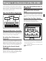
Chapter 1. an Overview of the JX-305
A brief explanation of the JX-305’s internal organization was provided in the Quick Start manual, but this
chapter contains a more detailed explanation of the
basic sections: the controller section, sound generating
section, and the sequencer section.
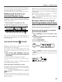
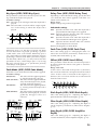
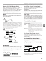
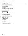
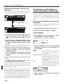
How the Sound Generator Is
Organized
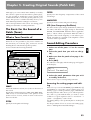
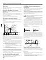
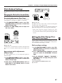
How the JX-305 Is Organized
Tones are the smallest unit of sound used by the JX305. Although it is possible to create a sound using
only one Tone, the sounds you will normally play on
the JX-305 are “Patches,” which consist of one or more
Tones.
fig.1-1TEXT (#MC fig.1-3)
Sound generator
section
Playback
Sequencer
section
Sounds That You Play—Patches
Patches are the unit of sound that you normally play.
Each Patch consists of up to four Tones.
Tones and Patches are organized as follows.
Recording
Performance
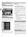
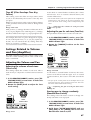
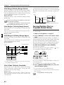
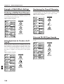
The Smallest Unit of Sound—
Tones
REALTIME MODIFY
fig.1-2TEXT (=MC fig.1-4)
ENVELOPE
LFO 1
EFFECTS
ATTACK
DECAY
SUSTAIN
RELEASE
DEPTH
FILTER
CUTOFF
RESONANCE
RATE
FADE TIME
PITCH DEPTH
FILTER DEPTH
AMP DEPTH
AMP
LEVEL
PANPOT
REVERB LEVEL
DELAY LEVEL
MULTI CTRL1
MULTI CTRL 2
MULTI CTRL 3
PITCH
PORTA TIME
FINE TUNE
PATCH
TONE 4
TONE 3
TONE 2
TONE 1
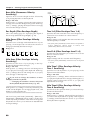
Controller section (keyboard, knobs, etc.)
Playing and Operation—Controller
Controllers refer collectively to the keyboard, the
panel knobs, the pitch bend lever, and the pedal connected to the rear panel etc. By operating these controllers you can play sounds or modify them.
Recording Your Performance—
Sequencer
The sequencer can record your playing and controller
operations (knob movements) as MIDI messages, and
can play back the MIDI messages that were recorded.
MIDI messages that have been recorded on the
sequencer can also be transmitted from the MIDI OUT
connector, and used to control external MIDI devices.
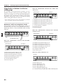
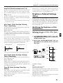
Producing the Sound—Sound
Generator
LFO 1
LFO 2
LFO 1
LFO 1
LFO 2
LFO 2
LFO 1
LFO 2
Cyclically modify the sound
Cyclically modify the sound
FILTER
AMPLIFIER
Modify the
brightness of
the sound
Modify the volume
PITCH ENV
FILTER ENV
AMPLIFIER ENV
Modify the pitch
over time
Modify the brightness
over time
Modify the volume
over time
WAVE
PITCH
Select the basic waveform
Modify the pitch of the
sound
COMMON
Make common settings
* The way in which the four tones are combined will determine how they will sound. This is determined by the
Structure Type parameter.
☞ “Settings Common to the Entire Patch
(Common)” (p. 77)
This is the section that produces the sound. The sound
generator produces sound in response to data it
receives from the JX-305’s controllers and its
sequencer. It can also be played by MIDI messages
that arrive from an external MIDI device.
13
1
Chapter 1. an Overview of the JX-305
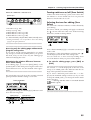
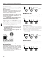
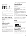
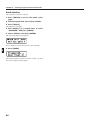
Playing Percussion Instruments—
Rhythm Sets
A collection of various percussion instruments
(rhythm tones) is referred to as a Rhythm Set. A different rhythm tone can be assigned to each key (note
number), allowing you to use a large number of
rhythm tones at once.
fig.1-3 (=MC fig.1-5)
RHYTHM SET
1
RHYTHM TONE (B5)
RHYTHM TONE (D5)
RHYTHM TONE (C4)
RHYTHM TONE (B1)
WAVE
PITCH
FILTER
AMPLIFIER
PITCH
ENV
FILTER
ENV
AMPLIFIER
ENV
Assigning Instruments to the
Ensemble—Parts
You can think of “Parts” as slots into which Patches
are placed. They can be thought of as being a little like
musicians. You can select a patch (instrument) for each
part (musician), and play multiple parts at once. The
JX-305 has eight parts for pattern playback, and you
can adjust the volume and pan etc. for each part.
fig.1-4TEXT (#MC fig.1-6)
Sound generator section
Part 1
Patch
Setup parameters
Part 2
Patch
Setup parameters
Part 3
Patch
Setup parameters
Part 4
Patch
Setup parameters
Part 5
Patch
Setup parameters
Part 6
Patch
Setup parameters
Part 7
Patch
Setup parameters
R Part
Rhythm Set
Setup parameters
Parts 1–7
For each of these parts, you can select a patch and play
melodic, bass or chordal instruments. Since it is also
possible to select an individual rhythm tone, you can
also use one of these parts as an auxiliary rhythm part.
14
Rhythm part
For this part, you can select a rhythm set and play percussion instrument sounds.
About simultaneous polyphony
The JX-305 is able to play up to 64 notes simultaneously. If the incoming musical data requests more than 64
notes simultaneously, some notes will drop out. When
using patches with a long release time or when using
RPS, be careful not to exceed the maximum simultaneous polyphony. The number of notes that can be
sounded will actually depend not only on the number
of notes being played, but also on the number of tones
that are used by each patch.
For example, if you are playing a patch that uses four
tones, that patch will take up four times the number of
notes that are played.
If you would like to know about the polyphony
settings...
● The Voice Priority parameter can be set for
each patch to specify how notes will be turned
off when the maximum polyphony is exceeded.
☞ “Settings Common to the Entire Patch
(Common)” (p. 77)
● The Voice Reserve parameter can be set to
specify a minimum number of notes that will
be reserved for each part.
☞ “Specifying the Number of Notes for Each
Part (Voice Reserve)” (p. 169)
How the Sequencer Is Organized
The sequencer records your performance and controller operations as musical data. Playing back the
sequencer will cause this recorded musical data to be
sent to the sound generator, making it produce sound.
In other words, the sequencer plays the instrument
instead of the musician.
In the sense that it records and plays back a performance, a sequencer is similar to a tape recorder.
However, it has unique advantages: the tempo can be
modified without affecting the pitch, there is no
decrease in sound quality no matter how many times
you play something back, and extremely detailed edits
can be made at will.
Musical Data Played Back by the
Sequencer—Patterns
Patterns are musical data of various genres for the
sequencer to play back, and can be selected even while
they play back. The data within each pattern is divided into parts, and you can record or play back each
part separately, or modify the musical data inside each
part. For each pattern, you can also specify things such
as the patch, volume and effect settings that will be
used by each part.
Chapter 1. an Overview of the JX-305
You can save the data in the condition that will be
most appropriate, and change the settings as a whole
simply by changing the pattern. These settings can
also be used when you play the keyboard directly.
PRESET
P:A11
USER
CARD
U:A11
C:A11
fig.1-5TEXT (#MC fig.1-7)
Sequencer
section
Sound source
section
PTN P:A13
PTN P:A11
Part 1
Part 1 data
Part 2
Part 2 data
Part 3
Part 3 data
Part 4
Part 4 data
Part 5
Part 5 data
Part 6
Part 6 data
Part 7
Part 7 data
R Part
Part 1 data
1
Part 3 data
Part 6 data
R Part data
R Part data
Currently playing
Pattern
Parts settings
(Patch selection and
setup parameters)
A Pattern Set lets you collect frequently used patterns
so that they can be recalled instantly. Sixteen patterns
can be registered in each pattern set.
fig.1-6TEXT
Pattern set example
Preset
User
Card
P:A11
U:A11
C:A11
NUMBER
1
1
P:A23
BD
U:A14
2
2
P:B14
2
SD
U:A15
3
3
U:A26
3
HH
U:A15
4
4
C:A12
4
4
1
50
About Memory
Part 7 data
Collecting Frequently Used
Patterns—Pattern Sets
1
3
Part 5 data
There are two types of patterns: “Preset Patterns”
which are already built into the JX-305, and “User
Patterns” which can contain patterns that you create.
BANK
2
Part 4 data
Switch
patterns
playback
Parts for pattern
playback
P:A14 U:A17 P:A24 C:A13 .... P:A35
Part 2 data
CLP
P:A85
5
Memory for Settings That Affect the
Entire JX-305—System Memory
System Memory contains settings for the system parameters that configure the JX-305. These include parameters that determine the overall operation of the
sound generator or sequencer, and MIDI-related settings.
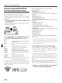
Rewritable Memory—User Memory
5
U:A12
5
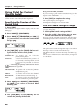
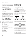
“Memory” refers to the place where patch settings and
musical data for patterns and other things are kept.
The memory of the JX-305 is divided into three areas:
System Memory, User Memory, and Preset Memory.
There is also a “temporary area” within memory, into
which data is placed when you select a patch or pattern, and the data in the temporary area is what you
are actually playing and editing.
CYM
P:B81
6
6
P:A55
6
TOM/PERC
P:B73
7
7
P:A56
7
HIT
U:A11
8
R
PART
C:A14
8
OTHERS
RHYTHM
P:A12
The contents of User Memory can be overwritten, and
are used to store settings or musical data that you create. User Memory stores 256 patches, 200 patterns, 50
songs, 60 RPS sets, and 30 pattern sets.
* At the factory settings, the User Patches and the User
Patterns have the same contents as Preset Memory.
Registered
pattern
Arranging Patterns in Playback
Order—Songs
A sequential arrangement of two or more patterns is
called a “song.” When you play back a song, the patterns in the song will play back in succession. A song
can contain up to 50 patterns.
Non-Rewritable Memory—Preset
Memory
The contents of Preset Memory cannot be rewritten.
Preset Memory contains 640 patches and 768 patterns.
fig.1-7TEXT (#MC fig.1-8)
15
Chapter 1. an Overview of the JX-305
1
Temporary Memory—The Temporary
Area (Temporary Pattern)
Basic Operation
When you play a sound or select a patch for editing,
the selected patch is called into a location known as
the “temporary area.”
When you edit or record a pattern, the contents of the
pattern are automatically copied to TMP (temporary
pattern), and your operations will affect this data.
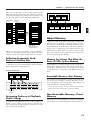
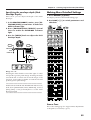
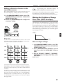
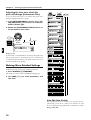
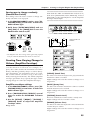
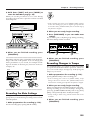
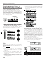
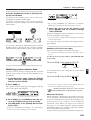
Modifying a Value
To select a patch or pattern, or to modify a parameter
value, use the VALUE dial or the INC/DEC buttons.
fig.1-9
VALUE
PAGE
Memory Card
An optional memory card can be used to store 512
User Patches and 200 User Patterns, just as in the user
memory of the JX-305.
LOWER
UPPER
SHIFT
UNDO
/ REDO
EXIT
ENTER
ERASE
DEC
INC
DEMO
fig.1-8TEXT (#MC fig.1-9)
MEMORY CARD
JX-305
INC button/DEC button
SYSTEM
PRESET
USER
CARD
PATCH
PATCH
PATCH
640
256
512
PTN
PTN
PTN
200
200
768
SONG
50
PTN SET
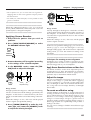
To increase a value press [INC]. To decrease a value
press [DEC].
If you continue pressing the button, the value will continue to change.
If you press one button while holding down the other
button, the value will change rapidly.
If you hold down [SHIFT] and press a button, the
value will change in larger steps.
30
RPS SET
60
TEMPORARY AREA
* The data in memory will be preserved even if the power is
turned off, and can be recalled at any time. However, the
data in the temporary area will be lost when the power is
turned off.
When you modify the settings of a patch or the contents of
a pattern, you are actually modifying the data that was
called into the temporary area or the temporary pattern.
(In other words, you are not directly modifying the data
in memory.) If you wish to keep the changes that you have
made to the patch or pattern, you must save the data as a
user patch or user pattern.
☞ “Saving Patches You’ve Created (Patch
Write)” (p. 82)
☞ “Saving Patterns You’ve Modified (Pattern
Write)” (p. 36)
16
VALUE dial
To increase a value, rotate the [VALUE] dial clockwise. To decrease a value, rotate the [VALUE] dial
counterclockwise.
If you hold down [SHIFT] as you rotate the [VALUE]
dial, the value will change in larger steps.
Chapter 1. an Overview of the JX-305
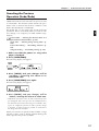
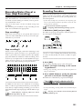
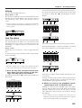
Canceling the Previous
Operation (Undo/Redo)
The function which lets a modified parameter value or
edited musical data to be restored to its previous state
is called Undo. The function which returns the parameter value or musical data from its “Undone” state
back to the edited state is called Redo.
The JX-305 lets you use undo/redo for the following
operations. This is convenient when you wish to cancel a change, or to compare your edits with the original data.
Pattern Edit ☞ “Editing the Musical Data of a
Specified Part (Pattern Edit)” (p. 138)
Song Edit ☞ “Editing Songs (Song Edit)” (p.
155)
Pattern Recording ☞ “Recording Patterns” (p.
125)
Song Recording ☞ “Recording a Song” (p. 155)
1
1. Make sure that the pattern or song select
page is displayed.
2. Press [UNDO/REDO].
The following display will appear.
fig.1-10 (#MC fig.1-11)
UNDO
/ REDO
ERASE
3. Press [ENTER], and your changes will be
“undone,” restoring the value to its
unmodified state.
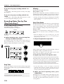
4. Press [UNDO/REDO] once again.
The following display will appear.
fig.1-11 (#MC fig.1-12)
5. Press [ENTER], and your changes will be
“redone,” returning the value to its edited state.
* Undo/Redo operations must be done immediately after
you modify the data. Once you save the modified pattern,
the undo/redo operation will no longer be available. Also,
if you use a different operation to make a further change
to the data, it will no longer be possible to undo/redo to
the change that was made first.
When you execute an operation that modifies a large
amount of data, such as during pattern editing, the
Undo operation may not be available.
17
Chapter 2. Playing the Keyboard
Selecting a Patch
* The card group cannot be selected unless a separately sold
memory card is inserted.
The JX-305 contains a total of 640 different patches.
By specifying the group, bank, and number, you can
select the desired patch and play it on the keyboard.
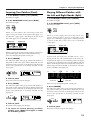
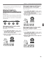
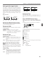
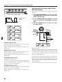
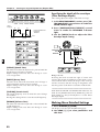
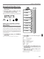
1. Press [PART SELECT].
The indicator lights.
2. Use PART [1]–[R] to select the part that you
wish to play on the keyboard.
fig.2-1
2
GROUP
PART
PRESET
PREV
USER
PART
SELECT
NEXT
MUTE
CTRL
EDIT
UTILITY
CARD
QTZ SELECT
BANK
1
1
2
2
3
3
4
4
FX ON/OFF
5
5
6
6
7
7
WRITE
8
R
PART
The currently selected part is referred to as the “current part.”
If the current part is a part 1–7 you can select patches.
If the current part is the rhythm part, you can select
rhythm sets.
☞ “Playing a Rhythm Set” (p. 28)
3. In the DISPLAY section, press [PATCH].
The indicator lights, and the display will show the
group, bank, number and name of the currently selected patch (rhythm set).
fig.2-2E
Bank
Group
Number
Name
Current part
4. In the GROUP section, press [PRESET/USER/
CARD] to select the group.
Patch groups are organized as follows.
PRESET-> P: A–J (Preset Group)
USER-> U: A–D (User Group)
CARD-> C: A–H (Card Group)
fig.2-3
GROUP
USER
CARD
18
6. Press [PART SELECT] once again.
The [PART SELECT] indicator goes out, and you can
now use BANK and NUMBER [1]–[8] to select a patch.
7. Use BANK [1]–[8] to select a bank.
* If the [PART SELECT] or [PART MUTE] indicators in
the PART section are lit, steps 7 and 8 will not be possible. In this case, press [PART SELECT] or [PART
MUTE] to make the indicators go dark.
* You can also select patches by using [INC] [DEC] or the
[VALUE] dial instead of specifying the group/bank/number.
To view a list of the available patches...
☞ “Preset Patch List” (p. 190)
Playing Two Patches from
the Keyboard (Key Mode)
The JX-305 lets you layer two patches, or play different
patches with the right and left hands. This function is
called the Key Mode.
The Key Mode setting can be stored as part of each
pattern.
☞ “Saving Patterns You’ve Modified (Pattern
Write)” (p. 36)
PATCH
PRESET
5. In the GROUP section, use [< PREV] [NEXT
>] to select the group (A–J, A–D, A–H).
8. Use NUMBER [1]–[8] to select a number.
Play the keyboard, and you will hear the selected
patch.
EDIT/UTILITY
PART
MUTE
☞ “Using Memory Cards” (p. 159)
Playing One Patch Over the
Entire Keyboard (Single)
This is the state in which you will normally play the
keyboard.
1. In the KEYBOARD section, make sure that
the [DUAL] and [SPLIT] indicators are dark.
If either indicator is lit, press the button and get the
indicator to go out.
fig.2-4
SPLIT
DUAL
Chapter 2. Playing the Keyboard
Layering Two Patches (Dual)
1. In the DISPLAY section, press [PATCH].
The indicator lights.
2. In the KEYBOARD section, press [DUAL].
The indicator lights.
fig.2-5
SPLIT
DUAL
Playing Different Patches with
the Left and Right Hands (Split)
1. In the DISPLAY section, press [PATCH].
The indicator lights.
2. In the KEYBOARD section, press [SPLIT].
The indicator lights.
fig.2-9
SPLIT
When you select Dual, the following screen will
appear. The part shown in the right of the upper row
is called the “upper part,” and the part shown in the
left of the upper row is called the “lower part.”
fig.2-6
Lower part
Upper part
DUAL
When you select Split, the following screen will
appear. The part that is shown in the right of the
upper row is called the “upper part,” and the part that
is shown in the left of the lower row is called the
“lower part.”
fig.2-6
Lower part
Upper part
Patch name
When you play the keyboard, the patches of the lower
part and the upper part will sound simultaneously.
Next, try changing the patch of each part.
3. Press [LOWER].
The indicator lights. The group, bank and number of
the patch for the lower part will be displayed in bold
characters. The lower line of the display will show the
name of the patch that is currently selected for the
lower part.
fig.2-7
fig.2-10TEXT
C3
C4
C5
C6
C7
UPPER
4. Select a patch.
The patch of the lower part changes.
5. Press [UPPER].
The indicator lights. The group, bank and number of
the patch for the upper part will be displayed in bold
characters. The lower line of the display will show the
name of the patch that is currently selected for the
upper part.
fig.2-8
PAGE
LOWER
In Split mode, the keyboard is divided into two areas.
Playing the left area will sound the patch of the lower part,
and playing the right area will sound the patch of the upper
part. The note at which the keyboard is devided into left and
right is called the Split Point. For example if the split point is
C4, the keyboard will be divided as shown below. The split
point is included in the Upper part.
C2
PAGE
LOWER
Patch name
Split point
Lower part
Upper part
Here’s how to change the patch of each part:
3. Press [LOWER].
The indicator lights. The group, bank and number of
the patch for the lower part will be displayed in bold
characters. The lower line of the display will show the
name of the patch that is currently selected for the
lower part.
fig.2-7
UPPER
PAGE
LOWER
6. Select a patch.
The patch of the upper part changes.
7. To return to normal playing condition
(Single), press [DUAL] once again to make
the indicator go dark.
UPPER
4. Select a patch.
The patch of the lower part will change.
19
2
Chapter 2. Playing the Keyboard
5. Press [UPPER].
The indicator lights. The group, bank and number of
the patch for the upper part will be displayed in bold
characters. The lower line of the display will show the
name of the patch that is currently selected for the
upper part.
fig.2-8
PAGE
want to assign to the upper part.
fig.2-16-1
BANK
1
1
2
2
3
3
4
4
5
5
6
6
7
7
8
R
PART
S E T U P
KEYBOARD
EFFECTS
PART
ARPEGGIO
CONTROLLER
MIDI
SEQUENCER
SETUP
SYSTEM
TONE SWITCH
1
2
3
4
1
2
3
4
TONE SELECT
4. Press [LOWER].
The indicator on the PART button for the part currently selected as the lower part will light.
fig.2-17
LOWER
2
PAGE
UPPER
6. Select a patch.
The patch of the upper part will change.
7. To return to normal play mode (Single),
press [SPLIT] once again to make the indicator go dark.
LOWER
5. Press PART [1]–[R] to select the part you
want to assign to the lower part.
fig.2-17-1
BANK
Changing the Split Point
UPPER
1
1
2
2
3
3
4
4
5
5
6
6
7
7
8
R
PART
S E T U P
KEYBOARD
EFFECTS
PART
ARPEGGIO
CONTROLLER
MIDI
SEQUENCER
SETUP
SYSTEM
TONE SWITCH
1
2
3
4
1
2
3
4
TONE SELECT
The split point can be changed freely.
1. Hold down [SPLIT] and press the key that
you wish to set as the split point.
fig.2-14
* If you assign the same part to both the upper part and
lower part, it will not be possible to select patches independently.
Modifying the Key Mode
Settings in the Editing Pages
SPLIT
fig.2-13-0
EDIT
1
1
PAGE
LOWER
Selecting the Upper Part/Lower Part
FX ON/OFF
UPPER
KEYBOARD
Key modes other than Single use two parts (the Upper
part and Lower part). You can select which of the
eight parts will be used as the Upper part, and which
will be used as the Lower part.
* When the Key Mode is Single, the upper part will be
played by the keyboard.
1. Press [PART SELECT].
The indicator lights.
fig.2-15
1. Press [EDIT].
The indicator lights, and the Edit page appears.
PART
SELECT
2. Press BANK [1] (KEYBOARD).
The display will show the Split Point setting page.
QTZ SELECT
fig.2-13
2. Press [UPPER].
The indicator on the PART button for the part currently selected as the upper part will light.
fig.2-16
PAGE
LOWER
UPPER
3. Press PART [1]–[R] to select the part you
20
3. Use [INC] [DEC] or the [VALUE] dial to set
the value.
Range: C-1–G9
* The Split Point settings is not affected by Octave Shift.
For example, middle C will be "C4" regardless of the
Octave Shift setting.
Chapter 2. Playing the Keyboard
4. Press PAGE [>] to select the upper part setting page.
fig.2-13-1
FILTER
AMP
PITCH
5. Use [INC] [DEC] or the [VALUE] dial to select
the upper part.
Range: PART 1–7, PART R
6. Once again press PAGE [>] to select the
lower part setting page.
fig.2-13-2
2. Rotate the [PORTA TIME] knob to adjust the
portamento time value.
Range: 0–127
Rotating the knob clockwise will lengthen the time
over which the pitch changes to that of the next note.
Rotating the knob counterclockwise will shorten the
time.
fig.2-20
7. Use [INC] [DEC] or the [VALUE] dial to select
the lower part.
Range: PART 1–7, PART R
8. Press [EXIT] to return to the normal display.
FILTER
CUTOFF
AMP
LEVEL
PITCH
PORTA TIME
Smoothly Changing the Pitch
of the Sound (Portamento)
Portamento is a function which smoothly changes the
pitch from one note to the next. It is effective when
playing single-note lines.
Portamento On/Off
1. In the KEYBOARD section, press [PORTAMENTO].
The indicator lights, and portamento will be turned on.
fig.2-18
PORTAMENTO
2. Each time you press [PORTAMENTO], the
function will be switched on or off.
Changing the Time Over Which the
Pitch Changes (Portamento Time)
You can change the speed at which the pitch will
change when portamento is used.
Portamento settings can be stored as part of the patch.
☞ “Saving Patches You’ve Created (Patch
Write)” (p. 82)
Playing Notes Which Lie Outside the
Range of the Keyboard (Octave Shift)
Octave Shift is a function which shifts the range of the
keyboard in one-octave steps (maximum +/- 3
octaves).
For example, bass notes can be easily played with the
right hand if you first use Octave Shift to lower the
range by one or two octaves.
1. In the KEYBOARD section, press OCTAVE [-]
[+].
The range will be shifted in the -/+ direction, and the
button indicator lights.
fig.2-21
OCTAVE
OCTAVE
1. In the REALTIME MODIFY section, press [FILTER/AMP/PITCH] several times, until the
PITCH indicator lights.
fig.2-19
21
2
Chapter 2. Playing the Keyboard
Each time you press OCTAVE [+], the range will be
raised one octave.
Each time you press OCTAVE [-], the range will be
lowered one octave.
While an OCTAVE button is pressed, the display will
indicate the current setting.
Changing the Pitch (Pitch Bend Lever)
By moving the pitch bend lever (located at the left of
the keyboard) to left or right, you can change the pitch
of the sound.
2
fig.2-22
If you wish to specify the parameter affected by
the modulation lever...
☞ “Specifying the Parameters That Will Be
Modified by Each Controller (Control)” (p. 76)
Using Aftertouch
Pressure which is applied to the keyboard after playing a note is referred to as "aftertouch." Aftertouch can
be used to apply change to the sound.
To specify the parameter that will be affected
when aftertouch is applied...
☞ “Specifying the Parameters That Will Be
Modified by Each Controller (Control)” (p. 76)
●●●●●●●●●●●●●●●●●●●●●●●●●●●●●●●●●●●●●●●●●●●●●●●●●●●●●●●●●●●●●●●●●●●●●●●●●●●●●●●●●●●●●●●●●●●●●●●●●●●●
BENDER
If you wish to modify the range of pitch
change...
☞ “Adjusting the Range of Pitch Bend (Bend
Range)” (p. 76)
●●●●●●●●●●●●●●●●●●●●●●●●●●●●●●●●●●●●●●●●●●●●●●●●●●●●●●●●●●●●●●●●●●●●●●●●●●●●●●●●●●●●●●●●●●●●●●●●●●●●
Parts affected by the Pitch Bend lever
The part(s) affected by the pitch bend lever will
depend on the Key Mode.
Single : The effect will be applied to the current part.
Split: The effect will be applied to the upper part
when the [UPPER] indicator is lit, and to the
lower part when the [LOWER] indicator is lit.
Dual: Regardless of the [UPPER]-[LOWER] selection, the effect will be applied to both parts.
●●●●●●●●●●●●●●●●●●●●●●●●●●●●●●●●●●●●●●●●●●●●●●●●●●●●●●●●●●●●●●●●●●●●●●●●●●●●●●●●●●●●●●●●●●●●●●●●●●●●
Applying Modulation to the Sound
Using the Modulation Lever
Parts that will be affected
The part(s) affected by the modulation lever or aftertouch will depend on the Key Mode.
Single: The effect will be applied to the current part.
Split: The effect will be applied to the upper part
when the [UPPER] indicator is lit, and to the
lower part when the [LOWER] indicator is lit.
Dual: Regardless of the [UPPER]-[LOWER] selection, the effect will be applied to both parts.
●●●●●●●●●●●●●●●●●●●●●●●●●●●●●●●●●●●●●●●●●●●●●●●●●●●●●●●●●●●●●●●●●●●●●●●●●●●●●●●●●●●●●●●●●●●●●●●●●●●●
Changing the Keyboard
Dynamics (Keyboard Velocity)
The force with which you play the keyboard is called
“velocity.” Velocity can be used to affect the volume
or the way in which each note sounds.
1. Press [EDIT].
The indicator lights, and the edit page will appear in
the display.
2. Press BANK [5] (CONTROLLER).
The Velocity setting page will appear.
fig.2-41
You can use the Modulation lever to apply changes to
the sound.
fig.2-26
BENDER
Since the sound will change only when the modulation lever is tilted away from you, this can be used to
add accents to your playing.
22
3. Use [INC] [DEC] or the [VALUE] dial to set
the value.
Range:
REAL: The velocity value will correspond to the strength
with which you actually play the note.
1–127: A fixed velocity value will be produced,
regardless of how strongly you play.
Chapter 2. Playing the Keyboard
4. Press [EXIT] when finished making the setting.
The original display will reappear.
The keyboard velocity setting has now been made.
Control Pedal Settings
Sustaining the Notes You
Play (Hold Pedal)
2. Press BANK [5] (CONTROLLER).
The CONTROLLER setting page will appear.
When a pedal switch is connected to the Hold Pedal
jack, notes can be sustained while you continue pressing the pedal. Newly played notes will be layered onto
the currently sounding notes. This is the same function
as the damper pedal of a piano.
1. Press [EDIT].
The indicator lights, and the editing page will appear.
3. Press PAGE [<] [>] several times to select
the Control Pedal Assign page.
fig.2-38
2
●●●●●●●●●●●●●●●●●●●●●●●●●●●●●●●●●●●●●●●●●●●●●●●●●●●●●●●●●●●●●●●●●●●●●●●●●●●●●●●●●●●●●●●●●●●●●●●●●●●●
Parts that will be held
The part(s) that will be held will depend on the Key
Mode.
Single: The current part will be held.
Split: The upper part will be held when the
[UPPER] indicator is lit, and the lower part
will be held when the [LOWER] indicator is
lit.
Dual: Both parts will be held, regardless of the
[UPPER]-[LOWER] selection.
●●●●●●●●●●●●●●●●●●●●●●●●●●●●●●●●●●●●●●●●●●●●●●●●●●●●●●●●●●●●●●●●●●●●●●●●●●●●●●●●●●●●●●●●●●●●●●●●●●●●
If you wish to know about the Hold Pedal setting...
☞ “Specifying How the Pedal Will Function”
(p. 163)
Using a Pedal to Modify the
Sound (Control Pedal)
If you connect an expression pedal to the control pedal
jack, you can use the pedal to modify the volume and
tonal character of the sound.
●●●●●●●●●●●●●●●●●●●●●●●●●●●●●●●●●●●●●●●●●●●●●●●●●●●●●●●●●●●●●●●●●●●●●●●●●●●●●●●●●●●●●●●●●●●●●●●●●●●●
4. Use [INC] [DEC] or the [VALUE] dial to specify the MIDI message that will be transmitted when the pedal is pressed.
Range:
CC 01–95:
Controller numbers 1–95
(except for 6, 32, 38)
PITCH BEND UP:
Pitch Bend Up
PITCH BEND DOWN: Pitch Bend Down
AFTERTOUCH:
Aftertouch
5. Once again press PAGE [>] to select the
Control Pedal Polarity page.
fig.2-40
6. Use [INC] [DEC] or the [VALUE] dial to set
the value.
Range: STANDARD, REVERSE
If you are using a pedal whose polarity is inverted
(i.e., when the pedal operation is opposite that of what
you expect), select “REVERSE.”
7. Press [EXIT] to complete the setting.
The original display will reappear.
Parts that will be controlled
The part(s) that will be controlled by the Control pedal
will depend on the Key Mode.
Single: The sound of the current part will be controlled.
Split: The upper part will be controlled when the
[UPPER] indicator is lit, and the lower part
when the [LOWER] indicator is lit.
Dual: Regardless of the [UPPER]-[LOWER] selection, the effect will be applied to both parts.
●●●●●●●●●●●●●●●●●●●●●●●●●●●●●●●●●●●●●●●●●●●●●●●●●●●●●●●●●●●●●●●●●●●●●●●●●●●●●●●●●●●●●●●●●●●●●●●●●●●●
23
Chapter 2. Playing the Keyboard
Pressing Chords to Produce
Arpeggios (Arpeggiator)
By using the arpeggiator, you can produce an arpeggio (broken chord) simply by holding down the chord.
For example, if you hold down a C major chord as follows, an arpeggio of C3, E3, G3, E3, C3, E3, G3.... will
be played.
In the case of
Arpeggio Style: 1/4
Octave Range: 0
fig.2-42(=MC fig.5-1)
2
C3
E3
G3
E3
C3
E3
G3
E3
Dual:
Arpeggios can be played on either the upper
or the lower, or on both the upper and lower.
For details refer to “Selecting the Part in Dual
Mode Which Will Play the Arpeggio
(Arpeggio Destination)” (p. 26)
●●●●●●●●●●●●●●●●●●●●●●●●●●●●●●●●●●●●●●●●●●●●●●●●●●●●●●●●●●●●●●●●●●●●●●●●●●●●●●●●●●●●●●●●●●●●●●●●●●●●
●●●●●●●●●●●●●●●●●●●●●●●●●●●●●●●●●●●●●●●●●●●●●●●●●●●●●●●●●●●●●●●●●●●●●●●●●●●●●●●●●●●●●●●●●●●●●●●●●●●●
Arpeggio Hold
If you hold down [HOLD] and press [ARP], and get
the indicator to start blinking, the arpeggio will continue sounding even after you take your fingers off the
keyboard. If you play a different chord or notes while
the arpeggio is being held, the arpeggio will change
accordingly.
To cancel Arpeggio Hold, hold down [HOLD] and
press [ARP] simultaneously once again.
fig.2-44
ARP
C3
E3
HOLD
G3
Playing Arpeggios
Also, if you connect a pedal switch (sold separately) to
the Hold Pedal jack, you can hold the arpeggio as long
as the pedal switch is pressed.
●●●●●●●●●●●●●●●●●●●●●●●●●●●●●●●●●●●●●●●●●●●●●●●●●●●●●●●●●●●●●●●●●●●●●●●●●●●●●●●●●●●●●●●●●●●●●●●●●●●●
1. Use [PART SELECT] and PART [1]–[R] to
select the part to be used to play arpeggios.
2. In the ARPEGGIATOR/RPS section, press
[ARP].
The indicator lights, and the arpeggiator will be
turned on.
fig.2-43
ARP
Creating an Arpeggio Pattern
When you wish to make arpeggiator settings, you will
first select an Arpeggio Style. When you select a style,
optimal values will be set for the four parameters
“Accent Rate,” “Motif,” “Beat Pattern,” and “Shuffle
Rate.” You can adjust parameters such as Accent Rate
and Octave Range to modify the pattern to your taste.
If this is not enough, you can also make more detailed
settings.
☞ “Making More Detailed Settings” (p. 26)
3. When you play the keyboard, any chord
you play will be sounded as an arpeggio.
* The tempo of the arpeggio will be synchronized to the
tempo of the pattern. If you wish to change the speed of
the arpeggio, change the tempo of the pattern.
☞ “Adjusting the Tempo” (p. 31)
●●●●●●●●●●●●●●●●●●●●●●●●●●●●●●●●●●●●●●●●●●●●●●●●●●●●●●●●●●●●●●●●●●●●●●●●●●●●●●●●●●●●●●●●●●●●●●●●●●●●
Parts that can be used for arpeggios
The part(s) that will sound the arpeggio will depend
on the Key Mode.
Single: Arpeggios can be played on the current part.
Split: Regardless of the [UPPER]-[LOWER] selection, arpeggios can be played only on the
lower part.
24
The arpeggiator settings you modify can be stored as a
User Style.
☞ “Saving Arpeggio Settings (Arpeggio Write)”
(p. 28)
Chapter 2. Playing the Keyboard
Changing the Way in Which the
Arpeggio Will Play (Arpeggio Style)
Specifies the basic way in which the arpeggio will be
played. Select one of the following 53 types.
1. Hold down [ARP] in the ARPEGGIATOR/RPS
section, and use [INC] [DEC] or the [VALUE]
dial to select the style.
While you hold down the button, the display will indicate the currently-selected style.
fig.2-45(#MC fig.5-4)
Available Settings:
1/4: The rhythm will be divided in quarter notes.
1/6: The rhythm will be divided in quarter note
triplets.
1/8: The rhythm will be divided in eighth notes.
1/12: The rhythm will be divided in eighth note
triplets.
1/16: The rhythm will be divided in 16th notes.
1/32: The rhythm will be divided in 32nd notes.
PORTAMENTO A, B: A style using the portamento
effect.
GLISSANDO: A glissando style.
SEQUENCE A–D: Styles for sequenced patterns.
ECHO: An echo-like style.
SYNTH BASS, HEAVY SLAP, LIGHT SLAP, WALK
BASS: Styles appropriate for bass playing.
RHYTHM GTR 1–5: Styles for guitar cutting. Styles
2–5 are effective when 3–4 notes are held.
3 FINGER: Three-finger guitar style.
STRUMMING GTR: A style simulating a guitar
chord strummed upward (downward). Effective when
5–6 notes are held.
PIANO BACKING, CLAVI CHORD: Styles for keyboard instrument backing.
WALTZ, SWING WALTZ: Styles in triple meter.
REGGAE: A reggae-type style. Effective when 3 notes
are held.
PERCUSSION: A style suitable for percussive instrument sounds.
HARP: The playing style of a harp.
SHAMISEN: The playing style of a Shamisen.
BOUND BALL: A style suggestive of a bouncing ball.
RANDOM: A style in which the notes sound in random order.
BOSSANOVA: A style with bossanova guitar cutting.
Hold 3–4 notes for best results. You can increase the
BPM and use this as a Samba.
SALSA:Typical salsa style. Hold 3–4 notes for best
results.
MAMBO: Typical mambo style. Hold 3–4 notes for
best results.
LATIN PERCUSION: A rhythm style with Latin percussion instruments such as Clave, Cowbell, Clap,
Bongo, Conga, Agogo etc.
SAMBA: Typical samba style. Use for rhythm patterns
or bass lines.
TANGO: Typical tango rhythm style. Hold the root,
3rd and 5th of a triad etc. for best results.
HOUSE: A style for house piano backing. Hold 3–4
notes for best results.
LIMITLESS: The settings of all parameters can be
freely combined without restriction.
USER STYLE 1–10: Arpeggio settings can be modified
and saved in one of these user styles.
Adding Expression to the
Arpeggio (Accent Rate)
By modifying the accent strength and note length, you
can change the sense of groove of the arpeggio.
1. Press [ACCENT RATE/OCTAVE RANGE] to
make the indicator go dark.
2. Rotate the [ACCENT RATE] knob to set the
accent rate.
fig.2-46
ACCENT
RATE
OCTAVE
RANGE
Rotating the knob clockwise will strengthen the sense
of groove. Rotating the knob counterclockwise will
decrease the amount of expression.
25
2
Chapter 2. Playing the Keyboard
Changing the Pitch Range of the
Arpeggio (Octave Range)
Making More Detailed Settings
1. Press [ACCENT RATE/OCTAVE RANGE] to
make the button indicator light.
Normally you will create the arpeggio pattern by
adjusting the three parameters “Arpeggio Style,”
“Accent Rate,” and “Octave Range.” However by
modifying the settings of additional parameters, you
can create arpeggio patterns that are even richer in
variation.
2. Rotate the [OCTAVE RANGE] knob to set the
Octave Range.
1. Press [EDIT].
The indicator lights, and the edit page appears.
You can specify the pitch range in which the arpeggio
will be developed, in steps of one octave.
fig.2-47
ACCENT
RATE
2
2. Press BANK [4] (ARPEGGIO).
The ARPEGGIO setting page will appear.
fig.2-48(#MC fig.5-7)
EDIT
4
4
PAGE
OCTAVE
RANGE
LOWER
FX ON/OFF
UPPER
ARPEGGIO
Rotating the knob clockwise will cause the pitch range
to be extended upward from the notes which you
play. Rotating the knob counterclockwise will extend
the pitch range downward.
Selecting the Part in Dual Mode
Which Will Play the Arpeggio
(Arpeggio Destination)
When the Key Mode is set to Dual, this setting specifies whether the upper and/or lower part will play
arpeggios.
1. Make sure that the [ARP] indicator is lit.
2. H o l d d o w n [ D U A L ] a n d u s e [ L O W E R ]
[UPPER] to select the destination part.
If you press [LOWER] [UPPER] simultaneously, the
destination part will be "LOWER&UPPER."
fig.2-48-0
DUAL
PAGE
LOWER
UPPER
Range:
LOWER&UPPER: The patches of the upper and
lower parts will be layered to
sound the arpeggio.
LOWER:
Arpeggios will be played only on
the lower part. For example, this
lets you play chords in the upper
part and arpeggios in the lower
part.
UPPER:
Arpeggios will be played only on
the upper part.
26
3. Use PAGE [<] [>] to select the parameter
page, and set the parameters.
To leave the setting page, press [EXIT].
Chapter 2. Playing the Keyboard
Style (Arpeggio Style)
This is the setting page for “Changing the Way in
Which the Arpeggio Will Play (Arpeggio Style)” (p.
25).
Motif
Specifies the order in which the notes of the chord will
be sounded.
Available Settings:
SINGLE UP: Notes you press will be sounded individually, beginning from low to high.
SINGLE DOWN: Notes you press will be sounded
individually, from high to low.
SINGLE UP&DOWN: Notes you press will be sounded individually, from low to high, and then back
down from high to low.
SINGLE RANDOM: Notes you press will be sounded
individually, in random order.
DUAL UP: Notes you press will be sounded two at a
time, beginning from low to high.
DUAL DOWN: Notes you press will be sounded two
at a time, beginning from high to low.
DUAL UP&DOWN: Notes you press will be sounded
two at a time, from low to high, and then back down
from high to low.
DUAL RANDOM: Notes you press will be sounded
two at a time, in random order.
TRIPLE UP: Notes you press will sound three at a
time, from low to high.
TRIPLE DOWN: Notes you press will sound three at
a time, from high to low.
TRIPLE UP&DOWN: Notes you press will sound
three at a time, from low to high and then back down
from high to low.
TRIPLE RANDOM: Notes you press will sound three
at a time, in random order.
NOTE ORDER: Notes you press will be sounded in
the order in which you pressed them. By pressing the
notes in the appropriate order you can produce
melody lines. Up to 128 notes will be remembered.
GLISSANDO: Each chromatic step between the highest and lowest notes you press will sound in succession, repeating upward and downward. Press only the
lowest and the highest notes.
CHORD: All notes you press will sound simultaneously.
BASS+CHORD 1–5: The lowest of the notes you play
will sound, and the remaining notes will sound as a
chord.
BASS+UP 1–8: The lowest of the notes you play will
sound, and the remaining notes will be arpeggiated.
BASS+RND 1–3: The lowest of the notes you play will
sound, and the remaining notes will sound in random
order.
TOP+UP 1–6: The highest of the notes you play will
sound, and the remaining notes will be arpeggiated.
BASS+UP+TOP: The highest and the lowest of the
notes you play will sound, and the remaining notes
will be arpeggiated.
* The parameters which can be set will depend on the currently-selected Arpeggio Style.
Beat Pattern
This allows you to select the Beat Pattern. It will affect
the accent location and note length, causing the beat
(rhythm) to change.
Range : 1/4, 1/6, 1/8, 1/12, 1/16 1–3, 1/32 1–3, PORTA-A
1–11, PORTA-B 1–15, SEQ-A 1–7, SEQ-B 1–5,
SEQ-C 1, 2, SEQ-D 1–8, ECHO 1–3, MUTE
1–16, STRUM 1–8, REGGAE 1, 2, REF 1, 2,
PERC 1–4, WALKBS, HARP, BOUND, RANDOM, BOSSA NOVA, SALSA 1–4, MAMBO
1–2, CLAVE, REV CLA, GUILO, AGOGO,
SAMBA, TANGO 1–4, HOUSE 1, 2
●●●●●●●●●●●●●●●●●●●●●●●●●●●●●●●●●●●●●●●●●●●●●●●●●●●●●●●●●●●●●●●●●●●●●●●●●●●●●●●●●●●●●●●●●●●●●●●●●●●●
If “PORTA-A 1–11, PORTA-B 1–15” is selected as the
Beat Pattern, the Patch parameter Portamento Time (p.
78) will control the speed of portamento. Adjust the
portamento time as appropriate for the playback
tempo. (It is not necessary to turn portamento on.)
●●●●●●●●●●●●●●●●●●●●●●●●●●●●●●●●●●●●●●●●●●●●●●●●●●●●●●●●●●●●●●●●●●●●●●●●●●●●●●●●●●●●●●●●●●●●●●●●●●●●
* The parameters which can be set will depend on the currently-selected Arpeggio Style.
Shuffle Rate
This setting lets you modify the note timing to create
shuffle rhythms.
Range: 50–90 (%)
With a setting of 50%, the notes will sound at equal
spacing. As this value is increased, the notes will
become more “bouncy,” as if they were dotted notes.
fig.2-49(=MC fig.5-8)
Shuffle Rate = 50%
50
50
50
Shuffle Rate =90%
50
90
10
90
10
* If the Beat Pattern setting is “1/4,” shuffle will not be
applied even if you increase the Shuffle Rate setting.
Accent Rate
This is the setting page for “Adding Expression to the
Arpeggio (Accent Rate)” (p. 25).
Range: 0–100
27
2
Chapter 2. Playing the Keyboard
Octave Range
This is the setting page for “Changing the Pitch Range
of the Arpeggio (Octave Range)” (p. 26).
Range: -3–+3
6. Press [ENTER] once again.
The Arpeggio Write operation will be executed, and
the normal display will reappear.
To cancel the operation without executing, press
[EXIT].
Velocity
2
Specify the loudness of the notes that you play.
Range: REAL, 1–127
If you want the velocity value to change according to
how strongly you played each note, set this to REAL.
If you want to produce a constant velocity value
regardless of how strongly each note was played,
specify the desired value.
Playing a Rhythm Set
The JX-305 contains various rhythm sets, each of
which have a different percussion instrument sound
or sound effect assigned to each key.
These rhythm sets can be selected by specifying the
group, bank and number, and are played from the
keyboard.
Destination
This is the setting page for “Selecting the Part in Dual
Mode Which Will Play the Arpeggio (Arpeggio
Destination)” (p. 26).
1. Use [PART SELECT] and PART [R] to select
the rhythm part.
fig.2-52
GROUP
PART
PRESET
Saving Arpeggio Settings
(Arpeggio Write)
When you have created a playback pattern that you
like, save the settings as a User Style. The JX-305 has
ten user styles, USER STYLE 1–10, and user styles that
you save can be recalled at any time.
* Velocity and Destination Part cannot be saved.
1. Create an arpeggio playback pattern.
2. Make sure that the ARPEGGIO setting page
is shown in the display.
If it is not displayed, press [EDIT] and then press
BANK [4] to access the setting page.
PREV
USER
PART
SELECT
NEXT
SHIFT
UTILITY
WRITE
MUTE
CTRL
EDIT
UTILITY
FX ON/OFF
WRITE
CARD
QTZ SELECT
BANK
1
1
2
2
3
3
4
4
5
5
6
6
7
7
8
R
PART
2. In the DISPLAY section, press [PATCH].
The indicator lights, and the display will show the
group, bank, number and name of the currently selected rhythm set.
fig.2-53E
Bank
Group
Number
PATCH
3. Hold down [SHIFT] and press [WRITE].
The indicator will blink, and the following display will
appear.
fig.2-50
EDIT/UTILITY
PART
MUTE
Name
3. In the GROUP section, press [PRESET/USER/
CARD] to select the group.
Rhythm set groups are organized as follows:
PRESET→ P: A, B (Preset group)
USER → U: (User group)
CARD → C: (Card group)
fig.2-3
4. Use [INC] [DEC] or the [VALUE] dial to specify the writing destination user style.
Range: USER STYLE 1–10
5. Press [ENTER].
The execute page will appear in the display.
GROUP
PRESET
USER
CARD
fig.2-51
* The Card group can be selected only when an optional
memory card is inserted.
28
Chapter 2. Playing the Keyboard
☞ “Using Memory Cards” (p. 159)
4. Press [PART SELECT] once again.
The [PART SELECT] indicator goes out, and you can
now use BANK and NUMBER [1]–[8] to select a
rhythm set.
5. Press BANK [1]–[4] to select the bank.
6. Press NUMBER [1]–[8] to select the number.
Play the keyboard, and the selected rhythm set will be
heard. Each key will play a different percussion instrument sound.
* If the [PART SELECT] or [PART MUTE] indicators in
the PART section are lit, steps 5 and 6 cannot be performed. In this case, press [PART SELECT] or [PART
MUTE] to make the indicator go dark.
1. Use [PART SELECT] and PART [1]–[R] to specify whether you will use an effects template for a patch or for a rhythm set.
For parts 1–7, use one of the patch effects templates.
For part R, use one of the rhythm set effects templates.
2. Hold down [SHIFT] and press [AUDITION].
The indicator will begin blinking, and the display will
show the effect type and patch name for the currently
selected effects template.
fig.2-3-2ÅiBUTTON&LCDÅj
SHIFT
PATCH
2
AUDITION
* Instead of specifying the group/bank/number, you can
also use [INC] [DEC] or the [VALUE] dial to select a
patch.
* Depending on the group and bank, it may not be possible
to select all numbers [1]–[8].
To view a list of available rhythm sets...
☞ “Preset Rhythm Set List” (p. 195)
Listening to Sound Processed
by the Effects (Audition)
The JX-305 contains three effects units. Thirty-two different settings for these three effects units, together
with a patch/rhythm set are provided as Effect
Templates (16 for patches, 16 for rhythm sets). The
Audition function lets you use these effects templates
to listen to the sound of a patch as it is processed by
the effects units. Effect templates are assigned to the
sixteen BANK and NUMBER [1]–[8] buttons.
fig.2-3-1Åi8-8BUTTONÅj
PATCH
St.Ac.Piano
PATCH
REVERB ROOM1
Ac.Piano 1
SHORT
DELAY
M-FX
REVERB
M-FX
3. Use BANK and NUMBER [1]–[8] to select an
effects template.
To see the effects templates that are available...
☞ “Effects Template List” (p. 203)
4. You can use [INC] [DEC] or the [VALUE] dial
to change only the patch without changing
the effects settings.
If you wish to modify the effects settings, use the procedure given in “Applying Effects to the Sound
(Effects)” (p. 101).
5. To exit the Audition function, press [EXIT].
* When you select a effects template, the setup parameters
of the temporary pattern will change to the settings of the
template.
* It is not possible to select the effects template while a pattern is playing back.
REVERB ROOM1
DELAY
* It is not possible to enter the audition function while a
pattern is playing back.
LONG
BANK
1
1
2
2
3
3
4
4
5
5
6
6
7
7
8
R
NUMBER
1
BD
2
SD
3
HH
4
CLP
5
CYM
6
TOM/PERC
7
HIT
8
OTHERS
PART
RHYTHM
* If you wish to keep the modified effects settings, it is not
possible to rewrite the template, but you can save the data
to a pattern.
☞ “Saving Patterns You’ve Modified (Pattern
Write)” (p. 36)
* A noise-like sound may be heard when the NUMBER [5]
template for rhythm sets is selected, but this is not a malfunction.
29
Chapter 3. Playing Patterns
A pattern has now been selected.
Playing Patterns
1. Make sure that the SEQUENCER section
[MODE] button indicator is dark.
If it is not dark, press [MODE] to make it go dark
(Pattern mode).
fig.3-1 (#MC fig.2-1)
MODE
PATTERN
SONG
* P:E33–P:L88 are RPS patterns. Each pattern contains
one phrase.
●●●●●●●●●●●●●●●●●●●●●●●●●●●●●●●●●●●●●●●●●●●●●●●●●●●●●●●●●●●●●●●●●●●●●●●●●●●●●●●●●●●●●●●●●●●●●●●●●●●●
Instead of using [INC] [DEC] or the [VALUE] dial,
you can also select patterns using BANK and NUMBER [1]–[8].
If you wish to use BANK and NUMBER [1]–[8] to
select patterns, make the [PART SELECT] and [PART
MUTE] indicators go dark.
●●●●●●●●●●●●●●●●●●●●●●●●●●●●●●●●●●●●●●●●●●●●●●●●●●●●●●●●●●●●●●●●●●●●●●●●●●●●●●●●●●●●●●●●●●●●●●●●●●●●
3
2. Press [PTN/SONG] in the DISPLAY section.
The indicator will light.
The display will indicate the group, bank, number and
name of the currently selected pattern.
fig.3-2E
6. Press [STOP/PLAY] and the pattern will
play back.
fig.3-4
STOP/PLAY
Bank
Group
Number
PTN /
SONG
Current part
Name
3. Press [PRESET/USER/CARD] in the GROUP
section to select the group.
Pattern groups are organized as follows.
PRESET → P:A–L (Preset group)
USER →
U:A–D (User group)
CARD → C:A–D (Card group)
The pattern that is currently playing back is referred to
as the “current pattern,” and the pattern that is scheduled to play next is called the “next pattern.”
Immediately after a pattern is played back, the current
pattern and the next pattern will be the same pattern,
and that pattern will play back repeatedly.
7. Use steps 3–5 to select the next pattern.
The display will indicate the group, bank, number and
name of the next pattern.
When you select the next pattern, the “ ” at the left
of the pattern group will change to “ .”
fig.3-4-1E
fig.3-3 (#MC fig.2-3)
Next pattern
GROUP
PRESET
USER
PREV
NEXT
CARD
* The card group can be selected only if an optional memory
card is inserted.
☞ “Using Memory Cards” (p. 159)
* When all three indicators of the GROUP section are dark,
TMP (the temporary pattern) is selected.
8. When the current pattern plays to the end,
the next pattern will automatically be
selected.
9. Press [STOP/PLAY] and the pattern will
stop playing.
fig.3-5
STOP/PLAY
4. Press [<PREV] [NEXT>] in the GROUP section to select group A–L.
5. Use [INC] [DEC] or the [VALUE] dial to select
the bank and number.
Range: P:A11–P:L88, U:A11–U:D18, C:A11–C:D18
The bank, number and name in the display will
change.
30
* Immediately before the pattern changes or repeats, the following display will appear, notifying you that the pattern
is about to change. During this time it is not possible to
select the next pattern.
fig.3-6E
Chapter 3. Playing Patterns
Adjusting the Tempo
The tempo can be adjusted freely even while a pattern
is playing back.
Current pattern
Next pattern
* If you press [STOP/PLAY] to stop playback after selecting the next pattern, the pattern that you had reserved
will be canceled.
* With the factory settings, the User group contain empty
patterns that contain no musical data. Even if you select
an empty pattern, it will not play back. If you specify an
empty pattern as the next pattern, playback will stop the
instant that the pattern changes.
●●●●●●●●●●●●●●●●●●●●●●●●●●●●●●●●●●●●●●●●●●●●●●●●●●●●●●●●●●●●●●●●●●●●●●●●●●●●●●●●●●●●●●●●●●●●●●●●●●●●
Fast-forward and rewind
Each time you press [FWD], the pattern will advance
one measure. Each time you press [BWD], the pattern
will go back one measure.
If you hold down [FWD] and press [BWD], you will
advance to the last measure. If you hold down [BWD]
and press [FWD], you will return to the beginning.
When a pattern is stopped, “ ” will sometimes be
displayed in the display. This indicates that the pattern was stopped in the middle of the measure.
fig.3-7
●●●●●●●●●●●●●●●●●●●●●●●●●●●●●●●●●●●●●●●●●●●●●●●●●●●●●●●●●●●●●●●●●●●●●●●●●●●●●●●●●●●●●●●●●●●●●●●●●●●●
●●●●●●●●●●●●●●●●●●●●●●●●●●●●●●●●●●●●●●●●●●●●●●●●●●●●●●●●●●●●●●●●●●●●●●●●●●●●●●●●●●●●●●●●●●●●●●●●●●●●
Changing patterns instantly
By holding down [SHIFT] and press PAGE [<] [>]
while a pattern is playing back, you can switch immediately to the previous or next pattern. In this case the
pattern will play back the optimal tempo for that pattern.
Also, if you make a new recording and create a pattern
that is only one measure long, and play back this pattern, it will in some cases be impossible to use [INC]
[DEC], the [VALUE] dial or PAGE [<] [>] to select the
next pattern. In such cases, holding down [SHIFT] and
use PAGE [<] [>] to change patterns.
●●●●●●●●●●●●●●●●●●●●●●●●●●●●●●●●●●●●●●●●●●●●●●●●●●●●●●●●●●●●●●●●●●●●●●●●●●●●●●●●●●●●●●●●●●●●●●●●●●●●
If you would like to know what kind of patterns are available...
☞ “Preset Pattern List” (p. 204)
1. In the DISPLAY section, press [TEMPO& MEASURE].
Indicator will light, and the upper line of the display
will show the current tempo value.
fig.3-8
TEMPO &
MEASURE
2. Use the [VALUE] dial to modify the tempo
(20.0–240.0 BPM).
The tempo can be adjusted in 0.1 BPM steps.
By holding down [SHIFT] and rotating the [VALUE]
dial, you can adjust the tempo in 1 BPM units.
●●●●●●●●●●●●●●●●●●●●●●●●●●●●●●●●●●●●●●●●●●●●●●●●●●●●●●●●●●●●●●●●●●●●●●●●●●●●●●●●●●●●●●●●●●●●●●●●●●●●
BPM
BPM stands for Beats Per Minute, and indicates the
number of quarter notes that occur in one minute.
Standard tempo
An optimal tempo is already set for each pattern. This
is called the “standard tempo.”
If you select another pattern while pattern playback is
stopped, the tempo will change to the standard tempo
of that pattern. When you use [INC] [DEC] or the
[VALUE] dial to switch to another pattern during pattern playback, the tempo value of the previous pattern
will be maintained.
●●●●●●●●●●●●●●●●●●●●●●●●●●●●●●●●●●●●●●●●●●●●●●●●●●●●●●●●●●●●●●●●●●●●●●●●●●●●●●●●●●●●●●●●●●●●●●●●●●●●
Viewing the Number of
Measures in a Pattern
If you wish to know the total number of measures in
the current pattern, or the current playback location,
use the following procedure.
1. Press [TEMPO&MEASURE].
The lower line of the display will show the number of
measures in the entire pattern, and the playback location (measure and beat). In the example shown below,
“Total number of measures = 16 measures” “Playback
location = third beat of measure 12”
fig.3-8 (#MC fig.2-8)
TEMPO &
MEASURE
2. To return to the pattern select page, press
[PTN/SONG].
31
3
Chapter 3. Playing Patterns
Muting a Specific Part (Part
Mute/Rhythm Mute)
During pattern playback, you can mute the playback
of a specific part or rhythm tone.
1. Press [PART MUTE].
The [PART MUTE] indicator will light, and the PART
button [1]– [R] indicators will show the current status
of that part.
The RHYTHM button [BD]– [OTHERS] indicators will
also show the current status of that rhythm group.
fig.3-11 (#MC fig.2-11)
PART
MUTE
3
●●●●●●●●●●●●●●●●●●●●●●●●●●●●●●●●●●●●●●●●●●●●●●●●●●●●●●●●●●●●●●●●●●●●●●●●●●●●●●●●●●●●●●●●●●●●●●●●●●●●
Other type of muting
In addition to Part Mute and Rhythm Mute, a variety
of other muting operations are available. Use them as
appropriate for your needs.
Simultaneously muting all parts (All Mute)
Hold down [SHIFT] and press [PART MUTE].
The indicator of [PART MUTE] will blink and all parts
will be muted. Perform the same operation once again
to return to the previous condition.
Playing back only a specific part (Monitor)
Hold down [PART MUTE] and press the PART button
for the part that you wish to hear.
Exchanging the mute status of all parts (Mute
Exchange)
Hold down [PART MUTE] and press [PART SELECT].
Blinking: The playback data is muted.
Lit:
The playback data is not muted.
Dark:
There is no playback data.
●●●●●●●●●●●●●●●●●●●●●●●●●●●●●●●●●●●●●●●●●●●●●●●●●●●●●●●●●●●●●●●●●●●●●●●●●●●●●●●●●●●●●●●●●●●●●●●●●●●●
2. Press the button of the part or rhythm
group that you wish to mute.
The indicator of the button you pressed will begin
blinking, and the playback data will be muted.
Transposing During Playback
(Real-Time Transpose)
fig.3-12 (#MC fig.2-12)
BANK
1
1
2
2
3
3
4
4
5
5
6
6
7
7
8
R
NUMBER
1
BD
2
SD
3
HH
4
CLP
5
CYM
6
TOM/PERC
7
HIT
8
OTHERS
PART
RHYTHM
To cancel muting, press the button for the muted part
or rhythm group to make the indicator light.
* The indicator will not light even if you press the button of
a part or rhythm group which is dark.
Using the VALUE Dial or [INC]
[DEC]
1. Hold down [TRANSPOSE] and use the
[VALUE] dial or [INC] [DEC] to specify the
transpose value.
Range: -12–+12 semitones (factory setting is +4)
fig.3-14 (#MC fig.2-16)
TRANSPOSE
* None of the preset patterns (P:A11-P:E32) contain playback data for part 1.
You can change the mute status of each part,
and save the setting in a user pattern.
☞ “Saving Patterns You’ve Modified (Pattern
Write)” (p. 36)
* Rhythm mute settings will not be active if the Part Mute
function has been used to mute the rhythm part itself.
* The rhythm tones that are muted by each RHYTHM button will depend on the selected rhythm set.
If you would like to know which rhythm tones
correspond to each rhythm group...
☞ “Preset Rhythm Set List” (p. 195)
32
The display will indicate the current setting while you
continue pressing the button. When you modify the
transpose value, the " " at the left of the transpose
value will change to " ."
2. The transposition will be applied from the
moment that you release the button.
To return to the original key, press [TRANSPOSE]
once again to make the button indicator go dark.
Chapter 3. Playing Patterns
Using the Keyboard
1. Hold down [TRANSPOSE] and press a key
to set the transpose value.
The transpose value can be set in a range of -12–+12
semitones, above and below the C4 key.
fig.3-15 (#MC fig.2-17)
1. Hold down [SHIFT] and press [MIXER].
The indicator will light and the display will show the
Part Mixer page.
2. Use PART [1]–[R] to select the part for
which you wish to make settings.
3. Use PAGE [<] [>] to select the parameter
that you wish to set.
TRANSPOSE
4. Use [INC] [DEC] or the [VALUE] dial to set
the value.
C4
●●●●●●●●●●●●●●●●●●●●●●●●●●●●●●●●●●●●●●●●●●●●●●●●●●●●●●●●●●●●●●●●●●●●●●●●●●●●●●●●●●●●●●●●●●●●●●●●●●●●
2. The transposition will be applied from the
moment that you press the keyboard.
To return to the original key, press [TRANSPOSE]
once again to make the button indicator go dark.
Changing the Settings of Each Part
The settings of a pattern (the volume and pan of each
part, etc.) can be modified in the following two ways.
When you enter the Part Mixer page, all indicators of
[ENVELOPE/LFO1/EFFECTS], [FILTER/AMP/PITCH]
and [GRID/SHUFFLE/GROOVE] will blink, and you
can use the eight knobs of the REALTIME MODIFY
section and the QUANTIZE section to adjust the settings of each part. At this time, the QUANTIZE settings or REALTIME MODIFY cannot be modified by
the knobs.
fig.3-17
1
2
3
Using the Part Mixer Page to
Make Changes
In the Part Mixer page, the setting values of each part
are displayed graphically. Here you can also record
the modified settings to a pattern.
☞ “Recording Part Mixer Operations” (p. 128)
fig.3-16
SHIFT
TEMPO &
MEASURE
LOWER
PART
5
6
7
R
REALTIME MODIFY
ENVELOPE
LFO 1
EFFECTS
ATTACK
DECAY
QUANTIZE
SUSTAIN
RELEASE
RATE
FADE TIME
PITCH DEPTH
FILTER DEPTH
AMP DEPTH
AMP
LEVEL
PANPOT
SHUFFLE
REVERB LEVEL
DELAY LEVEL
MULTI CTRL1
MULTI CTRL 2
MULTI CTRL 3
DEPTH
FILTER
PITCH
PORTA TIME
CUTOFF
RESONANCE
FINE TUNE
GROOVE
GRID
TIMING
VELOCITY
●●●●●●●●●●●●●●●●●●●●●●●●●●●●●●●●●●●●●●●●●●●●●●●●●●●●●●●●●●●●●●●●●●●●●●●●●●●●●●●●●●●●●●●●●●●●●●●●●●●●
5. Press [EXIT] to exit the Part Mixer page.
Adjusting the volume of each part
(Part Level)
PAGE
MIXER
4
UPPER
fig.3-18
Range: 0–127
With a setting of “127,” the volume setting of the patch
itself will be fully active.
Adjusting the pan of each part (Part Pan)
You can adjust the stereo location in the stereo output
from the OUTPUT jacks. For example, you might place
the drums and bass in the center, the piano at right,
and a pad at left.
fig.3-19
Range: L64–63R
33
3
Chapter 3. Playing Patterns
When this setting is at “0,” the setting of the patch
itself will be unaffected.
Adjusting the delay volume for each
part (Part Delay Level)
* Pan is specified independently for each tone of a patch (or
each rhythm tone of a rhythm set). Modifying the Part
Pan applies a relative change to the overall panning of the
patch or rhythm set.
You can adjust the volume of the delay sound for each
part.
* For some patches, a small amount of sound may be heard
from the opposite speaker even if the pan is set to full left
or full right. Also, the Part Pan setting will have no effect
in the following cases.
• When monaural connections are used
fig.3-22
Range: 0–127
☞ “Adding an Echo to the Sound (Delay)” (p.
103)
• Tones/rhythm tones for which Random Pan is ON
☞ “Causing pan to change randomly (Random
Pan Switch)” (p. 67)
Applying multi-effects to each part
(Part Multi-Effects Switch)
• Patches/rhythm tones to which a mono-output
Multi Effects (spectrum, overdrive, distortion, noise
generator, phonograph, limiter, phaser) is applied
For each part you can switch multi-effects on/off.
3
The same applies for the Lo-Fi or Radio Tuning
effects if the output setting of them is set to MONO.
☞ “Applying Various Effects to the Sound
(Multi-Effects)” (p. 106)
Adjusting the pitch of each part (Part
Key Shift)
You can adjust the pitch of the sound of each part.
fig.3-20
Range: -48–+48 semitones
When the value is “0,” the original pitch of the patch
itself will be used without change.
If you hold down [SHIFT] and change the value using
[INC] [DEC] or the [VALUE] dial, the pitch will
change in units of an octave (12 semitones).
Adjusting the reverb volume for each
part (Part Reverb Level)
You can adjust the volume of the reverberation for
each part.
fig.3-21
fig.3-23
Range:
OFF: Multi-effects will not be applied.
RHY: The sound will be output according to the
Rhythm Tone Multi-Effects Switch, Rhythm
Tone Reverb Level, and Rhythm Tone Delay
Level settings of the selected rhythm set (only
for the rhythm part) (p. 97).
ON: Multi-effects will be applied.
☞ “Applying Various Effects to the Sound
(Multi-Effects)” (p. 106)
Using the Editing Pages to Make
Changes
In the editing pages you can make settings for all part
parameters, but cannot record the modified settings to
a pattern.
1. Press [EDIT].
The indicator will light and the display will show the
Edit page.
2. Press BANK [3] (PART).
The part setting page will appear.
3. Use [PART SELECT] and PART[1]–[R] to select
the part.
Range: 0–127
☞ “Adding Reverberation to the Sound
(Reverb)” (p. 102)
34
4. Use PAGE [<] [>] to switch parameters.
5. Use [INC] [DEC] or the [VALUE] dial to make
settings.
fig.3-24
Chapter 3. Playing Patterns
EDIT
3
3
PAGE
LOWER
FX ON/OFF
UPPER
PART
Range: L64–63R
When this setting is at “0,” the setting of the patch
itself will be unaffected.
Adjusting the pitch of each part (Part
Key Shift)
You can adjust the pitch of the sound of each part.
fig.3-28
Range: -48–+48 semitones
When the value is “0,” the original pitch of the patch
itself will be used without change.
Adjusting the reverb volume for each
part (Part Reverb Level)
The volume of reverberation can be specified for each part.
fig.3-29
Range: 0–127
5. Press [EXIT] to leave the setting page.
Selecting the patch that will be
assigned to a part
The patch that is assigned to each part is memorized
as part of the pattern settings.
fig.3-25
☞ “Adding Reverberation to the Sound
(Reverb)” (p. 102)
Adjusting the delay volume for each
part (Part Delay Level)
The volume of the delay sound can be specified for
each part.
fig.3-30
Range: 0–127
Adjusting the volume of each part
(Part Level)
fig.3-26
☞ “Adding an Echo to the Sound (Delay)” (p.
103)
Applying multi-effects to each part
(Part Multi-Effects Switch)
Range: 0–127
With a setting of “127,” the volume setting of the patch
itself will be fully active.
Adjusting the pan of each part (Part
Pan)
You can adjust the stereo location in the stereo output
from the OUTPUT jacks.
fig.3-27
Multi-effects can be switched on/off for each part.
fig.3-31
Range:
OFF : Multi-effects will not be applied.
RHY : The sound will be output according to the
Rhythm Tone Multi-Effects Switch, Rhythm
Tone Reverb Level, and Rhythm Tone Delay
35
3
Chapter 3. Playing Patterns
Level settings of the selected rhythm set
(rhythm part only) (p. 97).
ON : Multi-effects will be applied.
☞ “Applying Various Effects to the Sound
(Multi-Effects)” (p. 106)
Specifying the output destination for
musical data
(Sequencer Output Assign)
3
You can specify the output destination for the musical
data of each part. For example, if you wish to use the
JX-305 together with a sampler such as the SP-202, you
can set Sequencer Output Assign to “EXT” for one or
more of the parts. This will allow playback data from
the JX-305 sequencer to control the external MIDI
device.
If you want to control an external MIDI device
such as a sampler...
☞ “Controlling an External MIDI Device from
the JX-305” (p. 174)
fig.3-32 (#MC fig.2-31&fig.2-32)
Musical data from parts that are set to EXT will be
transmitted as MIDI messages from MIDI OUT on a
different MIDI channel for each part.
The musical data of each part is transmitted on the following MIDI channels.
Part
1
2
3
4
5
6
7
R
Channel
1
2
3
4
5
6
7
10
●●●●●●●●●●●●●●●●●●●●●●●●●●●●●●●●●●●●●●●●●●●●●●●●●●●●●●●●●●●●●●●●●●●●●●●●●●●●●●●●●●●●●●●●●●●●●●●●●●●●
If you wish to use the keyboard to directly play an
external MIDI device, set the Local Switch to “EXT.”
☞ “Disconnecting the Keyboard from the
Internal Sound Generator (Local Switch)” (p.
165)
●●●●●●●●●●●●●●●●●●●●●●●●●●●●●●●●●●●●●●●●●●●●●●●●●●●●●●●●●●●●●●●●●●●●●●●●●●●●●●●●●●●●●●●●●●●●●●●●●●●●
Saving Patterns You’ve
Modified (Pattern Write)
If you have modified the patch and part mixer settings
for each part to create a pattern that you wish to keep,
you can save that pattern as a User Pattern.
1. Make sure that the pattern is stopped.
2. Press [PTN/SONG] to access the pattern
select page.
JX-305
Part 1
SEQ Out Assign = INT
Part 1
Part 2
SEQ Out Assign = INT
Part 2
Part 3
SEQ Out Assign = INT
Part 3
Part 4
SEQ Out Assign = INT
Part 4
Part 5
SEQ Out Assign = INT
Part 5
Part 6
SEQ Out Assign = INT
Part 6
Part 7
SEQ Out Assign = INT
Part 7
Part R
SEQ Out Assign =EXT
Part R
3. Hold down [SHIFT] and press [WRITE].
The indicator will blink.
The following display will appear, and “ ” (the cursor) will appear at the left of the number.
fig.3-33
SHIFT
MIDI OUT
SP-202
Range:
INT :
EXT :
BOTH :
WRITE
If you do not wish to change the number or name, you
can skip steps 4–8.
If you decide not to save the pattern, press [EXIT].
4. Press [PRESET/USER/CARD] to select the
save destination group.
Musical data from the sequencer will be
sent to the internal sound generator of the
JX-305.
Musical data from the sequencer will be
sent to an external device via MIDI OUT.
Musical data from the sequencer will be
sent both to the internal sound generator
and from MIDI OUT.
* If “EXT” or “BOTH” is selected, that part will not be
heard even if you play back the pattern.
36
UTILITY
* The PRESET group and TMP annot be selected.
* CARD groups can be selected only if an optional memory
card is inserted.
☞ “Using Memory Cards” (p. 159)
5. Use [INC] [DEC] or the [VALUE] dial to select
the save destination bank and number.
You can also use the BANK and NUMBER [1]–[8] buttons to select the save destination bank and number.
Chapter 3. Playing Patterns
●●●●●●●●●●●●●●●●●●●●●●●●●●●●●●●●●●●●●●●●●●●●●●●●●●●●●●●●●●●●●●●●●●●●●●●●●●●●●●●●●●●●●●●●●●●●●●●●●●●●
At this time, you can press [UNDO/REDO] to check
the name of the pattern that is currently in the save
destination number. After you have found a pattern
that you do not mind overwriting, press
[UNDO/REDO] once again to return to the previous
display.
●●●●●●●●●●●●●●●●●●●●●●●●●●●●●●●●●●●●●●●●●●●●●●●●●●●●●●●●●●●●●●●●●●●●●●●●●●●●●●●●●●●●●●●●●●●●●●●●●●●●
6. Press PAGE [>].
The cursor will move to the beginning of the second
line of the display.
fig.3-34
7. Assign a name to the pattern.
Use [INC] [DEC] or the [VALUE] dial to select characters.
The following characters are available.
space, A–Z, a–z, 0–9, ! “ # $ % & ‘ ( ) * +, - . / : ; < = > ?
@ [ ¥ ] ^ _ ` {|}
8. Repeat steps 6–7 to input the name.
You can move the cursor back toward the left by
pressing PAGE [<].
9. Press [ENTER].
The confirmation screen will appear in the display.
If you decide to cancel the operation, press [EXIT].
fig.3-35
Multi Effects settings (p. 106)
Part Mute status * (p. 32)
Rhythm Mute status (p. 32)
Sequencer Output Assign * (p. 36)
Key Mode # (p. 18)
Split Point # (p. 20)
Part number assigned to the upper part # (p. 20)
Part number assigned to the lower part # (p. 20)
* The “*” indicates parameters that are set independently
for each part.
* If you switch patterns while playback is stopped, “#” settings will be updated. However, if you switch patterns
during playback, These parameters will maintain the setting of the previous pattern.
These parameters are collectively referred to as the
“setup parameters.”
●●●●●●●●●●●●●●●●●●●●●●●●●●●●●●●●●●●●●●●●●●●●●●●●●●●●●●●●●●●●●●●●●●●●●●●●●●●●●●●●●●●●●●●●●●●●●●●●●●●●
Copying and Initializing Settings
Setup Copy
This operation copies the setup parameters of a specified pattern to the temporary pattern.
1. Press [PTN/SONG] to access the pattern
select page.
2. Press [UTILITY].
The indicator will light.
3. Press PAGE [<] [>] several times to select
“COPY,” and press [ENTER].
10. Press [ENTER] once again.
fig.0-5
4. Press PAGE [<] [>] several times to select
“SETUP PARAM,” and press [ENTER].
The display will indicate the copy source pattern, copy
source part, and copy destination part.
fig.3-37
The Pattern Write operation will be carried out, then
the normal display will reappear.
The pattern has now been saved.
●●●●●●●●●●●●●●●●●●●●●●●●●●●●●●●●●●●●●●●●●●●●●●●●●●●●●●●●●●●●●●●●●●●●●●●●●●●●●●●●●●●●●●●●●●●●●●●●●●●●
On the JX-305, the following parameters are memorized for each pattern.
Standard Tempo (p. 31)
Patch Number * (p. 18)
Part Level * (p. 33)
Part Pan * (p. 33)
Part Key Shift * (p. 34)
Part Reverb Level * (p. 34)
Part Delay Level * (p. 34)
Part Multi-Effects Switch * (p. 34)
Reverb settings # (p. 102)
Delay settings # (p. 103)
5. Use [INC] [DEC] or the [VALUE] dial to specify the copy source pattern, the copy source
part, and the copy destination part.
You can move the cursor by pressing PAGE [<] [>].
Available settings for the part:
P1–P7, R: Setup parameters of the specified part
FX:
Effects setup parameters
ALL:
All setup parameters
If the copy source part setting is “R,” “FX” or “ALL,”
it will not be possible to specify the copy destination
part.
6. Press [ENTER].
The confirmation screen will appear in the display.
If you decide to cancel the operation, press [EXIT].
fig.3-38
37
3
Chapter 3. Playing Patterns
Using the Knobs to Modify
the Sound During Playback
(Real-Time Modify)
7. Press [ENTER] once again.
fig.0-5
The Setup Copy operation will be carried out, then the
normal display will reappear.
To save the copied pattern, use the Pattern Write operation.
3
☞ “Saving Patterns You’ve Modified (Pattern
Write)” (p. 36)
You can freely modify the sound of a patch by moving
the sound parameter knobs while a pattern is playing.
This capability is referred to as Real-Time Modify, and
is especially effective when used during a live performance. Realtime Modify adjusts the tone of the entire
patch (rhythm set) selected for the current part, or the
tone of an entire rhythm group.
1. Select a pattern, and play it (p. 30).
2. Use [PART SELECT] and PART [1]–[R] to
select the part.
fig.2-1
GROUP
Pattern Initialize
This operation initializes a pattern to a state of containing no musical data (empty pattern).
PART
PRESET
PREV
USER
PART
SELECT
NEXT
EDIT/UTILITY
PART
MUTE
MUTE
CTRL
EDIT
UTILITY
CARD
QTZ SELECT
BANK
1
1
2
2
3
3
4
4
FX ON/OFF
5
5
6
6
7
7
WRITE
8
R
PART
1. Press [PTN/SONG] to access the pattern
select page.
2. Select the pattern that you wish to initialize.
* It is not posibble to initialize if you select a preset pattern.
3. Press [UTILITY].
The indicator will light.
4. Press PAGE [<] [>] several times to select
“INITIALIZE,” and press [ENTER].
5. Select “PATTERN,” and press [ENTER].
The following display will appear.
fig.3-40
●●●●●●●●●●●●●●●●●●●●●●●●●●●●●●●●●●●●●●●●●●●●●●●●●●●●●●●●●●●●●●●●●●●●●●●●●●●●●●●●●●●●●●●●●●●●●●●●●●●●
The part(s) affected by Realtime Modify
The part(s) whose sound will be affected by Realtime
Modify will depend on the Key Mode.
Single:
The sound of the current part will be
affected.
Split:
The sound of the upper part will be affected when the [UPPER] indicator is lit, and
the lower part when the [LOWER] indicator is lit.
Dual:
The sounds of both the upper and lower
parts will be affected.
●●●●●●●●●●●●●●●●●●●●●●●●●●●●●●●●●●●●●●●●●●●●●●●●●●●●●●●●●●●●●●●●●●●●●●●●●●●●●●●●●●●●●●●●●●●●●●●●●●●●
3. Use the knobs to modify the sound.
fig.3-43
6. Press [ENTER].
REALTIME MODIFY
fig.0-5
ENVELOPE
LFO 1
EFFECTS
The Pattern Initialize operation will be carried out,
then the normal display will reappear.
The pattern that was initialized will be saved automatically.
38
SUSTAIN
RELEASE
RATE
FADE TIME
PITCH DEPTH
FILTER DEPTH
AMP DEPTH
AMP
LEVEL
PANPOT
REVERB LEVEL
ATTACK
DELAY LEVEL
DECAY
MULTI CTRL1
MULTI CTRL 2
MULTI CTRL 3
DEPTH
FILTER
PITCH
PORTA TIME
CUTOFF
RESONANCE
FINE TUNE
* When modifying the rhythm part, parameters of LFO1
and PORTAMENTO are not used.
If you wish to learn about the function of each
knob and button...
☞“Creating Original Sounds (Patch Edit)” (p.
53)
☞“Creating an Original Rhythm Set (Rhythm
Edit)” (p. 85)
Chapter 3. Playing Patterns
●●●●●●●●●●●●●●●●●●●●●●●●●●●●●●●●●●●●●●●●●●●●●●●●●●●●●●●●●●●●●●●●●●●●●●●●●●●●●●●●●●●●●●●●●●●●●●●●●●●●
You can switch the current part during playback to
change the part that you are modifying.
●●●●●●●●●●●●●●●●●●●●●●●●●●●●●●●●●●●●●●●●●●●●●●●●●●●●●●●●●●●●●●●●●●●●●●●●●●●●●●●●●●●●●●●●●●●●●●●●●●●●
Modifying the Sound for an
Individual Rhythm Group
In the rhythm part, a different rhythm tone is assigned
to each key, and you can use Real-Time Modify to
modify the sound of rhythm tone groups such as Bass
Drum or Snare Drum.
1. Select a pattern, and play it (p. 30).
2. Select the rhythm part as the current part.
fig.2-52
GROUP
PART
PRESET
PREV
USER
PART
SELECT
NEXT
EDIT/UTILITY
PART
MUTE
MUTE
CTRL
EDIT
UTILITY
When the same pattern plays back repeatedly in
Pattern mode, the modified parameter settings will
remain as they are even if you return to the beginning
of the pattern.
These knob movements are referred to as “modify
data,” and can be recorded in a pattern.
☞ “Recording Knob Movements (Modify
Data)” (p. 128)
●●●●●●●●●●●●●●●●●●●●●●●●●●●●●●●●●●●●●●●●●●●●●●●●●●●●●●●●●●●●●●●●●●●●●●●●●●●●●●●●●●●●●●●●●●●●●●●●●●●●
Returning a Pattern to Its Original
State During Playback (Pattern Reset)
When you use Real-Time Modify, the pattern will
remain in its modified state until a different pattern is
selected. Here’s how you can restore a modified pattern to its original state during playback.
CARD
QTZ SELECT
BANK
1
1
2
2
3
3
4
4
FX ON/OFF
5
5
6
6
7
7
WRITE
8
R
PART
The indicator will light, and the RHYTHM buttons
will indicate the rhythm group that is selected for
Real-Time Modify.
fig.3-46 (#MC fig.2-48)
BD
SD
HH
CLP
CYM
TOM/PERC
HIT
OTHERS
Restoring only the patch of a specific
part that was modified
1. Press [PATCH] to access the patch select
page.
2. Select the part that you wish to restore as
the current part.
3. Press [UNDO/REDO].
The following display will appear.
fig.3-48-01
Select
Rhythm groups with button indicators that are lit will
be affected by Real-Time Modify.
For example, if you select [TOM/PERC], all toms and
percussion-type rhythm tones in the rhythm set can be
modified.
3. Press a button [BD]– [OTHERS] to select the
rhythm group that will be affected by RealTime Modify.
The indicator of the selected button will light.
UNDO
/ REDO
ERASE
4. Press [ENTER] to return to the previous
patch.
The “*” (asterisk) at the left of the patch number will
disappear.
fig.3-48-02
* It is not possible to select two or more groups simultaneously.
If no rhythm group is selected, all rhythm groups will
be affected by Realtime Modify.
4. Use the knobs to modify the sound.
●●●●●●●●●●●●●●●●●●●●●●●●●●●●●●●●●●●●●●●●●●●●●●●●●●●●●●●●●●●●●●●●●●●●●●●●●●●●●●●●●●●●●●●●●●●●●●●●●●●●
In addition to this, you can also modify each rhythm
tone in the Rhythm Edit page.
☞ “Creating an Original Rhythm Set” (Rhythm
Edit) (p. 85)
By selecting a different part or rhythm group, you can
change the object of your modifications even while the
pattern is playing.
39
3
Chapter 3. Playing Patterns
Restoring the patch (rhythm set) and
part mixer settings of all parts that
were modified
1. In the pattern select page, re-select the pattern that is currently playing (p. 30).
The pattern will return to the beginning, and the original settings will be restored.
●●●●●●●●●●●●●●●●●●●●●●●●●●●●●●●●●●●●●●●●●●●●●●●●●●●●●●●●●●●●●●●●●●●●●●●●●●●●●●●●●●●●●●●●●●●●●●●●●●●●
3
The relation between modify data that was
recorded and modify data from the knobs
If you perform Real-Time Modify while playing back a
part for which modify data has already been recorded,
the manual knob movements will take priority, and
the modify data within the musical data for that part
will be canceled, and will not be sent to the sound generator. (Note messages in the musical data will be sent
to the sound generator regardless of knob operations.)
fig.3-49TEXT (=MC fig.2-52)
Musical data of Part 1
Note data
Ensuring Correct Playback from
the Middle of a Pattern
(MIDI Update)
When a pattern is played back from the middle after
fast-forward or rewind, some parts (depending on the
pattern) may have incorrect pitch or volume. This is
because when you move to a different location within
a pattern, the musical data that was “skipped over” is
not transmitted to the sound generator. In such cases,
use the MIDI Update function so that the musical data
(other than note messages) that lies between the beginning of the pattern and the current location will be
transmitted to the sound generator, ensuring that
playback will occur correctly.
1. Make sure that the pattern is stopped.
2. Hold down [SHIFT] and press [STOP/PLAY].
While this operation is being performed, the following
display will appear.
fig.3-51 (#MC fig.2-54)
Modify data
SHIFT
STOP/PLAY
Sound
source
section
Note data
Modify data
Changing the Groove of a
Pattern (Play Quantize)
canceled
Realtime Modify begins
Modify data
from knob
movements
Modify Data that was canceled will once again be
transmitted to the sound generator when the pattern
returns to its beginning, or when you select a different
pattern.
* Each knob has eleven switching points as calibrated on the
panel. Modify Data within the musical data will be canceled from the moment that a knob is moved through one
of these points.
fig.3-50TEXT (#MC fig.2-53)
Switch point
Modify data is canceled
●●●●●●●●●●●●●●●●●●●●●●●●●●●●●●●●●●●●●●●●●●●●●●●●●●●●●●●●●●●●●●●●●●●●●●●●●●●●●●●●●●●●●●●●●●●●●●●●●●●●
40
Play Quantize is a function which modifies the pattern
that is being played back by correcting or skewing the
timing of the notes according to a specified rule. This
means that you can modify only the timing with
which the pattern will play back, without affecting the
contents of the data itself.
The JX-305 provides three types of quantization,
which you can use as appropriate for your situation.
You can apply Play Quantize to a specified part while
a pattern plays back, and make detailed timing adjustments in real time while you listen to the playback.
* Quantization affects only the timing of the note messages
(the timing at which notes are played and released), and
does not modify the timing of other messages. This means
that if a pattern contains messages (such as pitch bend)
that apply real-time change to the sound, quantization
settings may cause the timing of these messages to no
longer match the timing of the note messages, so that
playback will be incorrect. When applying quantization, it
is best to use a pattern which does not contain messages
that apply real-time change to the sound.
Chapter 3. Playing Patterns
Selecting Parts to Use with Play
Quantize
Play Quantize can be applied to the playback of a specific part. Before you apply Play Quantize, you must
specify the part(s) to which it will apply.
1. Hold down [SHIFT] and press [QTZ SELECT].
The button indicator will blink.
fig.3-52 (#MC fig.7-1)
PART
SELECT
SHIFT
GRID
SHUFFLE
GROOVE
3. Press [EDIT].
The indicator will light and the display will show the
Edit page.
4. Press NUMBER [7] (QUANTIZE).
The Grid Quantize setting page will appear.
QTZ SELECT
fig.3-55 (#MC fig.7-4)
EDIT
2. Use PART [1]–[R] to select the part(s) to
which you wish to apply Play Quantize.
Play Quantize will be applied to the parts whose indicators are lit.
7
HIT
PAGE
LOWER
FX ON/OFF
3
UPPER
QUANTIZE
fig.3-53 (#MC fig.7-2)
1
2
3
4
5
6
7
R
You can simultaneously select more than one part.
Correcting Inaccuracies in the
Rhythm (Grid Quantize)
Grid Quantize will quantize the pattern playback timing to the nearest specified note value. This will cause
the pattern to play back with accurate timing.
fig.3-54 (=MC fig.7-3)
5. Use [INC] [DEC] or the [VALUE] dial to set
the Resolution.
Range:
To exit the setting page, press [EXIT].
●●●●●●●●●●●●●●●●●●●●●●●●●●●●●●●●●●●●●●●●●●●●●●●●●●●●●●●●●●●●●●●●●●●●●●●●●●●●●●●●●●●●●●●●●●●●●●●●●●●●
When the GRID indicator is lit, you can also hold
down [GRID/SHUFFLE/GROOVE] and rotate the
[VALUE] dial to modify the Resolution.
●●●●●●●●●●●●●●●●●●●●●●●●●●●●●●●●●●●●●●●●●●●●●●●●●●●●●●●●●●●●●●●●●●●●●●●●●●●●●●●●●●●●●●●●●●●●●●●●●●●●
Applying Grid Quantize
* When Grid Quantize is used, the playback timing will be
correct, but conversely this may produce a mechanical,
inhuman feel. If you wish to preserve the feel of the performance, you can set Resolution to a fine value, or lower the
Strength setting.
1. Play back the pattern that you wish to
quantize.
2. Press [GRID/SHUFFLE/GROOVE] several
times to make the GRID indicator light.
fig.3-57 (#MC fig.7-6)
Specifying the Unit (Resolution)
The note value unit to which quantization will adjust
the timing is called the Resolution. The timing of notes
will be adjusted to the nearest grid interval of the note
value you specify here. Set this to the length of the
smallest note value that occurs in the pattern.
1. Press [PTN/SONG].
2. Press [GRID/SHFFLE/GROOVE] several
times to make the GRID indicator light.
fig.3-57
GRID
SHUFFLE
GROOVE
3. Grid Quantize will be applied to the playback data according to the Resolution setting.
4. In the QUANTIZE section, rotate the [TIMING] knob to adjust the Strength.
Range: 0–100%
fig.3-58 (#MC fig.7-7)
41
Chapter 3. Playing Patterns
3. Press [EDIT].
The indicator will light and the display will show the
Edit page .
TIMING
VELOCITY
100%
50%
0%
4. Press NUMBER [7] (QUANTIZE).
The Shuffle Quantize setting page will appear.
fig.3-60 (#MC =fig.7-9)
EDIT
7
HIT
PAGE
LOWER
Strength specifies the degree to which the note timing
will be corrected toward the note value specified by
Resolution. Rotating the knob clockwise will cause the
notes to be corrected all the way to their correct timing.
When this setting is at “0%,” the notes will be played
at their original (un-quantized) timing.
3
FX ON/OFF
UPPER
QUANTIZE
●●●●●●●●●●●●●●●●●●●●●●●●●●●●●●●●●●●●●●●●●●●●●●●●●●●●●●●●●●●●●●●●●●●●●●●●●●●●●●●●●●●●●●●●●●●●●●●●●●●●
In the Grid Quantize setting page, you can use PAGE
[<] [>] to access the Strength setting page and view the
numerical value of the knob setting while you apply
quantization.
5. Use [INC] [DEC] or the [VALUE] dial to specify the Resolution.
Range:
fig.3-58-1
To exit the setting page, press [EXIT].
●●●●●●●●●●●●●●●●●●●●●●●●●●●●●●●●●●●●●●●●●●●●●●●●●●●●●●●●●●●●●●●●●●●●●●●●●●●●●●●●●●●●●●●●●●●●●●●●●●●●
●●●●●●●●●●●●●●●●●●●●●●●●●●●●●●●●●●●●●●●●●●●●●●●●●●●●●●●●●●●●●●●●●●●●●●●●●●●●●●●●●●●●●●●●●●●●●●●●●●●●
When the SHUFFLE indicator is lit, you can also hold
down [GRID/SHUFFLE/GROOVE] and rotate the
[VALUE] dial to modify the Resolution.
Giving Swing to the Rhythm
(Shuffle Quantize)
Applying Shuffle Quantize
By applying Shuffle Quantize, you can adjust the timing of the backbeats of the pattern to create “bouncy”
rhythms such as shuffle or swing.
1. Play back the pattern that you wish to
quantize.
fig.3-59 (=MC fig.7-8)
●●●●●●●●●●●●●●●●●●●●●●●●●●●●●●●●●●●●●●●●●●●●●●●●●●●●●●●●●●●●●●●●●●●●●●●●●●●●●●●●●●●●●●●●●●●●●●●●●●●●
2. Press [GRID/SHUFFLE/GROOVE] several
times to make the SHUFFLE indicator light.
fig.3-62 (#MC fig.7-11)
Specifying the Unit (Resolution)
Specifies the Resolution. The timing of notes will be
adjusted to the nearest grid interval of the note value
you specify here. Set this to the length of the smallest
note value that occurs in the pattern.
1. Press [PTN/SONG].
2. Press [GRID/SHFFLE/GROOVE] several
times to make the SHUFFLE indicator light.
fig.3-62
GRID
SHUFFLE
GROOVE
3. Shuffle Quantize will be applied according
to the Resolution setting.
4. In the QUANTIZE section, rotate the [TIMING] knob to adjust the Shuffle Rate.
Range: 0–100 %
fig.3-63 (#MC fig.7-12)
GRID
SHUFFLE
GROOVE
TIMING
VELOCITY
42
0%
50%
100%
Chapter 3. Playing Patterns
Shuffle Rate refers to the degree to which the backbeats will bounce, and specifies the ratio by which the
backbeats will be separated from the downbeats.
When the knob is in the center position, this setting is
at 50%, and the backbeats will be located exactly
between the adjacent downbeats.
Rotating the knob clockwise will move the backbeats
later in time. Rotating the knob counterclockwise will
move the backbeats earlier in time.
0%:
Backbeats will fall at the same timing as the
preceding downbeat.
100%: Backbeats will fall at the same timing as the
following downbeat.
3. Press [EDIT].
The indicator will light and the display will show the
Edit page .
4. Press NUMBER [7] (QUANTIZE).
The Groove Quantize Template setting page will
appear.
fig.3-65 (=MC fig.7-14)
EDIT
7
HIT
PAGE
LOWER
FX ON/OFF
UPPER
QUANTIZE
●●●●●●●●●●●●●●●●●●●●●●●●●●●●●●●●●●●●●●●●●●●●●●●●●●●●●●●●●●●●●●●●●●●●●●●●●●●●●●●●●●●●●●●●●●●●●●●●●●●●
In the Shuffle Quantize setting page, you can use
PAGE [<] [>] to access the Shuffle Rate setting page,
and apply quantization while viewing the numerical
setting of the knob.
3
fig.3-63-1
●●●●●●●●●●●●●●●●●●●●●●●●●●●●●●●●●●●●●●●●●●●●●●●●●●●●●●●●●●●●●●●●●●●●●●●●●●●●●●●●●●●●●●●●●●●●●●●●●●●●
Giving a Groove to the Rhythm
(Groove Quantize)
Groove Quantize lets you select a template by which
the playback timing and the velocity will be quantized. Simply by selecting a different template, you can
give a variety of different-feeling grooves to a pattern.
The JX-305 contains 71 different types of quantization
templates, each of which contains a different set of
playback timing and velocity (dynamics) data.
fig.3-64 (=MC fig.7-13)
* The templates are for use with 4/4 time signatures. They
will not produce the desired result when applied to other
time signatures.
Selecting the Template
1. Press [PTN/SONG].
2. Press [GRID/SHFFLE/GROOVE] several
times to make the GROOVE indicator light.
fig.3-66
GRID
5. Use [INC] [DEC] or the [VALUE] dial to select
the template.
To exit the setting page, press [EXIT].
Available Settings:
16 Beat Dance type
01
02
03
04
05
06
07
08
09
10
11
12
:
:
:
:
:
:
:
:
:
:
:
:
Dance-Nm-L.Ac
Dance-Nm-H.Ac
Dance-Nm-L.Sw
Dance-Nm-H.Sw
Dance-Hv-L.Ac
Dance-Hv-H.Ac
Dance-Hv-L.Sw
Dance-Hv-H.Sw
Dance-Ps-L.Ac
Dance-Ps-H.Ac
Dance-Ps-L.Sw
Dance-Ps-H.Sw
exact/low dynamics
exact/high dynamics
exact/light swing
exact/strong swing
dragging/low dynamics
dragging/high dynamics
dragging/light swing
dragging/strong swing
rushing/low dynamics
rushing/high dynamics
rushing/light swing
rushing/strong swing
16 Beat Fusion type
13
14
15
16
17
18
19
20
21
22
23
24
:
:
:
:
:
:
:
:
:
:
:
:
Fuson-Nm-L.Ac
Fuson-Nm-H.Ac
Fuson-Nm-L.Sw
Fuson-Nm-H.Sw
Fuson-Hv-L.Ac
Fuson-Hv-H.Ac
Fuson-Hv-L.Sw
Fuson-Hv-H.Sw
Fuson-Ps-L.Ac
Fuson-Ps-H.Ac
Fuson-Ps-L.Sw
Fuson-Ps-H.Sw
exact/low dynamics
exact/high dynamics
exact/light swing
exact/strong swing
dragging/low dynamics
dragging/high dynamics
dragging/light swing
dragging/strong swing
rushing/low dynamics
rushing/high dynamics
rushing/light swing
rushing/strong swing
SHUFFLE
GROOVE
43
Chapter 3. Playing Patterns
16 Beat Reggae type
Others
25
26
27
28
29
30
31
32
33
34
35
36
61
62
63
64
65
66
67
68
69
70
71
:
:
:
:
:
:
:
:
:
:
:
:
Regge-Nm-L.Ac
Regge-Nm-H.Ac
Regge-Nm-L.Sw
Regge-Nm-H.Sw
Regge-Hv-L.Ac
Regge-Hv-H.Ac
Regge-Hv-L.Sw
Regge-Hv-H.Sw
Regge-Ps-L.Ac
Regge-Ps-H.Ac
Regge-Ps-L.Sw
Regge-Ps-H.Sw
exact/low dynamics
exact/high dynamics
exact/light swing
exact/strong swing
dragging/low dynamics
dragging/high dynamics
dragging/light swing
dragging/strong swing
rushing/low dynamics
rushing/high dynamics
rushing/light swing
rushing/strong swing
:
:
:
:
:
:
:
:
:
:
:
Samba 1
Samba 2
Axe 1
Axe 2
Salsa 1
Salsa 2
Triplets
Quintuplets
Sextuplets
7 against 2
Lagging Tri
samba (pandero)
samba (surdo and timba)
axe (caixa)
axe (surdo)
salsa (cascara)
salsa (conga)
triplets
quintuplets
sextuplets
seven notes played over two beats
lagging triplets
●●●●●●●●●●●●●●●●●●●●●●●●●●●●●●●●●●●●●●●●●●●●●●●●●●●●●●●●●●●●●●●●●●●●●●●●●●●●●●●●●●●●●●●●●●●●●●●●●●●●
3
8 Beat Pops type
37
38
39
40
41
42
43
44
45
46
47
48
:
:
:
:
:
:
:
:
:
:
:
:
Pops-Nm-L.Ac
Pops-Nm-H.Ac
Pops-Nm-L.Sw
Pops-Nm-H.Sw
Pops-Hv-L.Ac
Pops-Hv-H.Ac
Pops-Hv-L.Sw
Pops-Hv-H.Sw
Pops-Ps-L.Ac
Pops-Ps-H.Ac
Pops-Ps-L.Sw
Pops-Ps-H.Sw
exact/low dynamics
exact/high dynamics
exact/light swing
exact/strong swing
dragging/low dynamics
dragging/high dynamics
dragging/light swing
dragging/strong swing
rushing/low dynamics
rushing/high dynamics
rushing/light swing
rushing/strong swing
8 Beat Rhumba type
49
50
51
52
53
54
55
56
57
58
59
60
:
:
:
:
:
:
:
:
:
:
:
:
Rhumb-Nm-L.Ac
Rhumb-Nm-H.Ac
Rhumb-Nm-L.Sw
Rhumb-Nm-H.Sw
Rhumb-Hv-L.Ac
Rhumb-Hv-H.Ac
Rhumb-Hv-L.Sw
Rhumb-Hv-H.Sw
Rhumb-Ps-L.Ac
Rhumb-Ps-H.Ac
Rhumb-Ps-L.Sw
Rhumb-Ps-H.Sw
exact/low dynamics
exact/high dynamics
exact/light swing
exact/strong swing
dragging/low dynamics
dragging/high dynamics
dragging/light swing
dragging/strong swing
rushing/low dynamics
rushing/high dynamics
rushing/light swing
rushing/strong swing
Selecting a template
Templates are categorized by the three elements of
genre, groove, and variation.
Select the template which combines the desired elements.
Genre
Dance
Fuson
Regge
Pops
Rhumb
Others
:
:
:
:
:
:
16 beat dance
16 beat fusion
16 beat reggae
8 beat pops
8 beat rhumba
samba, axe, salsa, tuplets
Groove
Nm (Normal) : on the beat
Hv (Heavy) : ”dragging” the beat
Ps (Pushed) : ”rushing” the beat
Variation
L.Ac (Light Accent)
H.Ac (Hard Accent)
L.Sw (Light Swing)
H.Sw (Hard Swing)
:
:
:
:
light dynamics
heavy dynamics
light swing
strong swing
For example, in the case of a dance song where you
wish to drag the beat with light swing, you would
select “Dance-Hv-L.Sw.”
* The genre names are only a guideline, and do not mean
that those templates can be used only in the named genre.
Try out additional possibilities.
* If you apply Groove Quantize to musical data which contains inaccuracies in timing, you may not obtain the
desired results. In such cases, it is best to apply Grid
Quantize first, to bring the timing of the original musical
data into alignment with the printed notes.
44
Chapter 3. Playing Patterns
* The templates are for use with 4/4 time signatures.
Applying them to other time signatures may not produce
the desired result.
* For samba, axe, salsa and tuplet, it is not possible to select
groove or variation.
100% 50% 0%
100% 50% 0%
TIMING
VELOCITY
●●●●●●●●●●●●●●●●●●●●●●●●●●●●●●●●●●●●●●●●●●●●●●●●●●●●●●●●●●●●●●●●●●●●●●●●●●●●●●●●●●●●●●●●●●●●●●●●●●●●
Template velocity
●●●●●●●●●●●●●●●●●●●●●●●●●●●●●●●●●●●●●●●●●●●●●●●●●●●●●●●●●●●●●●●●●●●●●●●●●●●●●●●●●●●●●●●●●●●●●●●●●●●●
When the GROOVE indicator is lit, you can hold
down [GRID/SHUFFLE/GROOVE] and rotate the
[VALUE] dial to change the template.
●●●●●●●●●●●●●●●●●●●●●●●●●●●●●●●●●●●●●●●●●●●●●●●●●●●●●●●●●●●●●●●●●●●●●●●●●●●●●●●●●●●●●●●●●●●●●●●●●●●●
Applying Groove Quantize
1. Play back the pattern that you wish to
quantize.
2. Press [GRID/SHUFFLE/GROOVE] to make
the GROOVE indicator light.
fig.3-66 (#MC fig.7-15)
GRID
SHUFFLE
Range: 0–100%
Velocity Strength is the degree to which the velocities
of the pattern will be adjusted toward the velocities of
the template. As the knob is rotated clockwise, the
velocities that are played will be closer to the velocities
of the template.
When this setting is at “0%,” the notes will be played
at their original velocities.
●●●●●●●●●●●●●●●●●●●●●●●●●●●●●●●●●●●●●●●●●●●●●●●●●●●●●●●●●●●●●●●●●●●●●●●●●●●●●●●●●●●●●●●●●●●●●●●●●●●●
In the Groove Quantize setting page, you can also use
PAGE [<] [>] to access the Strength or Velocity
Strength setting pages, and use the knobs to adjust the
setting while you view the numerical setting of the
parameter.
●●●●●●●●●●●●●●●●●●●●●●●●●●●●●●●●●●●●●●●●●●●●●●●●●●●●●●●●●●●●●●●●●●●●●●●●●●●●●●●●●●●●●●●●●●●●●●●●●●●●
GROOVE
●●●●●●●●●●●●●●●●●●●●●●●●●●●●●●●●●●●●●●●●●●●●●●●●●●●●●●●●●●●●●●●●●●●●●●●●●●●●●●●●●●●●●●●●●●●●●●●●●●●●
3. Groove Quantize will be applied according
to the settings of the selected template.
Techniques for creating a sense of groove
Templates use a variety of means to produce an optimal performance result for Groove Quantize. Refer to
the following points as you use templates.
4. In the QUANTIZE section, rotate the [TIMING] knob to adjust the Strength.
Apply Groove Quantize to drums and bass lines
fig.3-67TEXT (#MC fig.7-16)
TIMING
VELOCITY
100%
50%
0%
Template timing
Range: 0–100%
Strength specifies the degree to which the note timing
will be corrected toward the timings specified by the
template. As the knob is rotated clockwise, the notes
will be corrected further toward the timing of the template.
When this setting is at “0%,” the notes will be played
at their original (un-quantized) timing.
5. Press [TIMING/VELOCITY] to make the indicator light, and rotate the [VELOCITY] knob
to adjust the Velocity Strength.
The drums and bass are the most important parts in
creating the groove. Thus, the templates are created to
match these instruments. It is best to apply Groove
Quantize only to instruments which need it.
Adjust the tempo
The groove templates have been created based on a
tempo in the range of q=120–140. When applying
Groove Quantize to a song with a faster tempo than
this, set Strength to 100% for maximum effectiveness.
For a song with a slower tempo than this, set Strength
below 100%.
To create an effective swing
Careful attention to the tempo is an important part of
creating an effective swing. For example, in the case of
jazz, it will be effective to apply deeper swing to songs
that have a slow tempo. Conversely, lightening the
swing for a faster tempo will give a greater sense of
speed. In another example, applying deeper swing to a
dance-type rhythm at a rapid tempo will produce a
feeling of “bounce.”
Try out various settings to find the most effective type
of swing.
●●●●●●●●●●●●●●●●●●●●●●●●●●●●●●●●●●●●●●●●●●●●●●●●●●●●●●●●●●●●●●●●●●●●●●●●●●●●●●●●●●●●●●●●●●●●●●●●●●●●
fig.3-68TEXT (#MC fig.7-17)
45
3
Chapter 3. Playing Patterns
Using Pedal for Control
(Switch Pedal)
A pedal switch connected to the SWITCH PEDAL jack
can be used to control the JX-305’s sequencer.
Specifying the Function of the
Switch Pedal
1. Press [EDIT].
The indicator will light and the display will show the
Edit page.
3
2. Press BANK [5] (CONTROLLER).
The Controller setting page will appear.
3. Press BANK [5] (CONTROLLER) or PAGE [<]
[>] several times to select the Switch Pedal
Assign page.
Range: STANDARD, REVERSE
If you are using a pedal with inverted polarity (so the
pedal functions in a way opposite from what you
expect), select “REVERSE.”
7. Press [EXIT] to complete the setting.
The original display will reappear.
Switch pedal settings have now been made.
Using the Pedal to Change the Tempo
You can modify the tempo by the interval at which
you press the pedal.
1. Set the pedal switch setting to “TAP.”
2. Press the pedal at least three times at quarter-note intervals of the desired tempo.
The tempo will be calculated automatically, and the tempo
will be changed to the interval at which you press the pedal.
fig.3-72
fig.3-70
TAP
4. Use [INC] [DEC] or the [VALUE] dial to specify the function of the switch pedal.
Range:
STOP/PLAY: The pedal will act like the
[STOP/PLAY] button.
PTN INC:
(Pattern Increment) The patterns of
the currently selected pattern set will
be successively selected as the next
pattern.
☞ “Collecting Frequently Used Patterns in a Set
(Pattern Set)” (p. 152)
TRANSPOSE: The pedal will act like the [TRANSPOSE] button (p. 32).
SHIFT:
The pedal will act like the [SHIFT]
button.
RPS HOLD:
The RPS function can be held (p. 49).
TAP:
The tempo will be modified to the
interval at which you press the pedal.
5. Once again press BANK [5] (CONTROLLER)
or PAGE [>] to select the Switch Pedal
Polarity page.
fig.3-71
6. Use [INC] [DEC] or the [VALUE] dial to
switch the polarity of the pedal.
46
TAP
TAP
The pedal can be used to change the tempo even when
the tempo value is not shown in the display.
The BEAT indicator will show the tempo and time signature.
The indicator will blink red on the first beat, and green
on other beats.
Chapter 3. Playing Patterns
Simultaneously Changing the
Tempo and Pitch (Turntable)
Turntable is a function which lets you use the pitch
bend lever and modulation lever to affect the playback
of a pattern. When you move the modulation lever, all
parts will be instantly muted. When you move the
pitch bend lever, the tempo and pitch will change
simultaneously, producing an effect similar to when
the pitch of a record turntable is changed.
1. Hold down [SHIFT] and move the modulation lever away from yourself.
The following screen will appear, and you will be able to use
the pitch bend lever to control the Turntable function.
fig.3-73
3
SHIFT
BENDER
2. Move the pitch bend lever to left and right.
The tempo and pitch of all parts will change simultaneously.
Moving the pitch bend lever toward the left will
simultaneously lower the tempo and pitch.
Moving it toward the right will simultaneously raise
the pitch. Returning the lever to its normal position
will restore the initial tempo and pitch.
* If the tempo of the pattern is fast, the tempo will not
increase even if the pitch bend lever is moved toward the
right.
3. Move the modulation lever away from
yourself.
While the modulation lever is moved away from yourself, all parts will be muted.
* The keyboard performance (including arpeggios) and RPS
playback will not be muted.
When the modulation lever is returned to its normal
position, the initial mute status will be restored.
4. To turn off the Turntable effect, once again
hold down [SHIFT] and move the modulation lever away from yourself.
The following screen will appear, and the pitch bend
lever and modulation lever will return to their normal
function.
fig.0-46-2
47
Chapter 4. One-Touch Phrase Playback (RPS)
RPS (Realtime Phrase Sequence) is a function which
lets you play back the musical data for one part of a
pattern simply by pressing a specified note. You can
play different phrases depending on the note that you
press. Since you can play back RPS phrases while you
play the keyboard or play back a pattern, this function
is ideal for use during a live performance, etc.
For example, if a drum fill-in phrase used by one pattern is assigned as an RPS, you can play back another
pattern without a fill-in, and then add the fill-in simply by pressing a key.
Pressing Notes to Play Back
Phrases
The RPS set is now selected.
* A brief interval of time is needed for the RPS set to
change. Also, if you change RPS sets during pattern playback, the pattern may slow down or falter, so it is best to
change RPS sets while pattern playback is stopped.
3. Press [RPS] to make the button indicator
light.
fig.4-3
RPS
4. Press a key to play back a phrase.
The phrase will play back while you continue pressing
the key.
●●●●●●●●●●●●●●●●●●●●●●●●●●●●●●●●●●●●●●●●●●●●●●●●●●●●●●●●●●●●●●●●●●●●●●●●●●●●●●●●●●●●●●●●●●●●●●●●●●●●
4
On the JX-305, phrases assigned to the sixteen notes
from C#2 to E3 are handled as one RPS set. The contents of an RPS set can be freely re-assigned later, and
sixty different RPS sets can be stored in memory. The
notes which can be used to assign phrases are the sixteen notes in the diagram except for the C2 note (RPS
Stop).
RPS Modify
While you are pressing a key to play an RPS, you can
move the Patch parameter knobs to modify the sound
of the RPS. If you are pressing two or more keys, You
can modify the sound of the key that was last pressed.
fig.4-2-MODIFY
RPS
fig.4-1TEXT (#MC fig.6-1)
RPS sample
Pattern P:A33
(phrase from Part 2)
CUTOFF
RPS
* It is not possible to modify an RPS while editing a
patch/rhythm set or when you enter the Part Mixer page.
* When you release the note, the sound of the current part
(not RPS) will be modified.
RPS STOP
1. In the DISPLAY section, press [RPS SET].
The indicator will light, and the display will indicate
the group, bank, number and name of the currently
selected RPS set.
fig.4-2TEXT (#MC fig.6-2)
Group
Bank
Number
RPS
SET
Name
2. Use [INC] [DEC] or the [VALUE] dial to select
the bank and number.
You can also use the BANK and NUMBER [1]–[8] buttons to select RPS sets.
Range: 11–84
The selection in the display will change.
48
RPS playback timing
If you use RPS while a pattern is playing back, the
phrase will start in synchronization with the beat of
the pattern.
By changing the RPS Trigger Quantize setting, you can
modify the timing at which the RPS will play back.
☞ “Specifying the Timing for RPS Playback
(RPS Trigger Quantize)” (p. 167)
Maximum simultaneous RPS playback
Even while a pattern is playing back, the JX-305 can
play back up to 8 phrases simultaneously. However, if
phrases with large amounts of data are played back
simultaneously, the timing may lag behind or notes
may be interrupted. If this occurs, decease the number
of phrases that you play simultaneously.
●●●●●●●●●●●●●●●●●●●●●●●●●●●●●●●●●●●●●●●●●●●●●●●●●●●●●●●●●●●●●●●●●●●●●●●●●●●●●●●●●●●●●●●●●●●●●●●●●●●●
Chapter 4. One Touch Phrase Playback (RPS)
Causing a Phrase to Continue
Playing (RPS Hold)
fig.4-5-1
RPS
Normally, the phrase will stop playing when you take
your finger off the note. However when the RPS Hold
function is used, the phrase will continue playing even
after you release the note.
There are two ways to hold an RPS phrase.
RPS STOP
Holding all phrases
1. Hold down [HOLD] and press [RPS].
The indicator will blink.
fig.4-4
HOLD
Key of phrase
to be stopped
4. To stop playback of all phrases, press the
note at the far left (RPS STOP).
fig.4-5-2
RPS
RPS
2. Press a note to play back a phrase.
The phrase will continue playing back even after you
release the note.
You can press additional notes while the indicator is
blinking, and their phrases will be held.
4
RPS STOP
3. To stop playback of a phrase, hold down
the note of the phrase that you wish to
stop, and press the note at the far left (RPS
STOP).
Alternatively, if you connect a pedal switch or foot
switch (optional) and set the System setting “Switch
Pedal Assign” to “RPS HOLD,” the pedal switch can
be used to hold RPS phrases in the same way as with
the [HOLD] button (p. 46).
4. To stop playback of all phrases, either
press the note at the far left (RPS STOP), or
once again press [RPS] and [HOLD] simultaneously.
Assigning Phrases to the
Keyboard
Holding a specific phrases
1. Press a note to play back the phrase that
you wish to hold.
2. While continuing to press the note, press
[HOLD].
The phrase will continue playing even after you
release the note.
If you release [HOLD] and then press and release
other notes, their phrases will not be held.
fig.4-5
The phrases that are assigned to an RPS set can be reassigned whenever you wish. You will find it convenient to assign your favorite or frequently-used phrases in one RPS set. As an example, here’s how to assign
the phrase of part 2 of P:A12 in an RPS set.
First we must select the RPS set in which we will
assign the phrase.
1. Select the RPS set to which you wish to
assign the phrase.
2. Select pattern P:A12.
3. Use [PART MUTE] and the PART buttons
[1]–[R] to mute all parts except for part 2.
RPS
HOLD
* You can quickly mute all parts except for part 2 by holding [PART MUTE] and pressing PART [2].
fig.4-6 (#MC fig.6-4)
GROUP
PART
PRESET
PREV
USER
PART
SELECT
NEXT
EDIT/UTILITY
PART
MUTE
MUTE
CTRL
EDIT
UTILITY
FX ON/OFF
WRITE
CARD
QTZ SELECT
3. To stop playback of a phrase, hold down
the note to which that phrase is assigned,
and press the note at the far left (RPS
STOP).
BANK
1
1
2
2
3
3
4
4
5
5
6
6
7
7
8
R
PART
4. Make sure that the [RPS] indicator is lit.
49
Chapter 4. One Touch Phrase Playback (RPS)
5. Hold down [RPS], and press the key to
which you wish to assign the phrase.
fig.4-7 (#MC fig.6-5)
RPS
RPS
The phrase will be assigned to the key that you
pressed.
Phrases can be assigned even while a pattern is playing back.
●●●●●●●●●●●●●●●●●●●●●●●●●●●●●●●●●●●●●●●●●●●●●●●●●●●●●●●●●●●●●●●●●●●●●●●●●●●●●●●●●●●●●●●●●●●●●●●●●●●●
4
P:E33–P:L88 contain patterns which are prepared
specifically for use with RPS. You might find it convenient to assign phrases from these patterns to use as
fill-ins, or for other situations.
* If a rhythm part phrase is assigned, the Rhythm Mute settings will be ignored during RPS playback.
* Each phrase is played back by a special RPS part 1–16
which corresponds to each key, but phrases assigned from
a rhythm part will be played back using the rhythm part
of the currently-selected pattern. For this reason, a different rhythm set than that of the registered pattern may
sound in some cases. If the pattern changes so that a different rhythm set is selected, the rhythm set which will
play the RPS will also change.
fig.4-9 (#MC fig.6-7)
PART R
PART 1 2 3 4 5 6 7
PA11 PA12 PA12 PA35 PA74 PA75 PA17 PA24 PA33 PB71 PA48 PA77 PA86 PA85 PA87 PA11
P-R P-2 P-1 P-R P-2 P-5 P-R P-4 P-2 P-4 P-6 P-6 P-7 P-7 P-3 P-4
1
2
3
4
5
6
7
8
9 10 11 12 13 14 15 16
RPS PART
●●●●●●●●●●●●●●●●●●●●●●●●●●●●●●●●●●●●●●●●●●●●●●●●●●●●●●●●●●●●●●●●●●●●●●●●●●●●●●●●●●●●●●●●●●●●●●●●●●●●
●●●●●●●●●●●●●●●●●●●●●●●●●●●●●●●●●●●●●●●●●●●●●●●●●●●●●●●●●●●●●●●●●●●●●●●●●●●●●●●●●●●●●●●●●●●●●●●●●●●●
Cautions when assigning an RPS
* It is not possible to assign phrases of two or more parts to
a single key. You must mute all but one of the parts, the
one with the desired phrase, before assigning it. If any of
the extra parts have been left unmuted when you make
your assignment, the following message will appear in the
display:
Checking the pattern number and part that
were registered
If you hold down a key to which an RPS was registered and press [PTN/SONG], the pattern number,
name and the part registered to that key will appear in
the display while you continue pressing the key.
fig.4-9-PART
fig.4-8 (=MC fig.6-6)
●●●●●●●●●●●●●●●●●●●●●●●●●●●●●●●●●●●●●●●●●●●●●●●●●●●●●●●●●●●●●●●●●●●●●●●●●●●●●●●●●●●●●●●●●●●●●●●●●●●●
* If after assigning a phrase from a user pattern as an RPS,
you then modify the playback data of the pattern which
contains that phrase, be aware that any change to the
phrase will also be reflected in the way it is played back by
RPS. For example, if you delete the musical data of the
pattern which contains the phrase that you assigned, there
will be no sound when you attempt to play back that
phrase by RPS.
* Even if you assign the phrase of a part that has a setting
of “BOTH” or “EXT” for its Sequencer Output Assign
(p. 36) parameter, the musical data of that phrase will not
be transmitted from MIDI OUT.
* If you assign a phrase from a part that uses multi-effects,
the RPS playback will use the multi-effects settings of the
pattern that is selected at that time. This means that what
you hear when the RPS plays back may be somewhat different from the original phrase.
Making Settings for Each
Phrase
Using the Part Mixer to Modify
Settings
You can use the part mixer to modify settings such as
volume and pan for each RPS part.
The following parameters can be modified for each
RPS part.
RPS Level (RPS Part Level)
RPS Panpot (RPS Part Pan)
RPS Key Shift (RPS Part Key Shift)
RPS Reverb (RPS Part Reverb Level)
RPS Delay (RPS Part Delay Level)
RPS M-FX SW (RPS Part Multi-Effects Switch)
1. Make sure that the [RPS] indicator is lit.
2. Hold down [RPS] and Press [MIXER].
50
Chapter 4. One Touch Phrase Playback (RPS)
The indicator will light, and the display will graphically show the current setting of each RPS part.
RPS PART
1 2 3 4 5
(9) (10) (11) (12) (13)
3. Press PAGE [<] [>] several times to select
the parameter that you wish to modify.
fig.4-10 (#MC fig.6-8)
6 7
(14) (15)
8
(16)
REALTIME MODIFY
TEMPO &
MEASURE
RPS
ENVELOPE
SUSTAIN
RELEASE
RATE
FADE TIME
PITCH DEPTH
FILTER DEPTH
AMP DEPTH
AMP
LEVEL
PANPOT
SHUFFLE
REVERB LEVEL
ATTACK
DELAY LEVEL
MULTI CTRL1
MULTI CTRL 2
MULTI CTRL 3
PITCH
PORTA TIME
FINE TUNE
GROOVE
LFO 1
EFFECTS
MIXER
PAGE
LOWER
UPPER
DECAY
QUANTIZE
DEPTH
FILTER
CUTOFF
RESONANCE
GRID
TIMING
VELOCITY
* Keys to which a rhythm part phrase is assigned will
reflect the rhythm part settings of the currently selected
pattern. For example, if RPS phrases using the rhythm
part are assigned to keys C#2 and D2, modifying the volume setting or rhythm set of C#2 key will cause the settings of D2 key and the rhythm part of the selected pattern to change in the same way.
Changing the Patch of Each RPS
Part
You can change the sound which plays each RPS part,
so that the phrase assigned to each key will be heard
with a different sound.
1. Hold down [RPS] and press [PATCH].
The indicator will light, and the following display will
appear.
fig.4-11 (#MC fig.6-9)
RPS
PATCH
Part4
4. Press a note to which a phrase has been
registered to switch the part shown in the
display.
If you press any note C#2–G#2, the settings of RPS
parts 1–8 will be graphically displayed.
If you press any note A2–E3, the settings of RPS parts
9–16 will be graphically displayed.
The right side of the display will indicate the current
setting value of the selected RPS part.
2. Press the note for the phrase whose patch
you wish to change to select the RPS part.
The display will indicate the patch of the selected RPS
part.
3. Use [INC] [DEC] or the [VALUE] dial to select
the desired patch.
You can also use the GROUP section [PRESET/USER/
CARD], [<PREV] [NEXT>] and BANK and NUMBER
[1]–[8] buttons to select a patch.
* If you change the rhythm set of a key to which a rhythm
part phrase is registered, the rhythm set of the currently
selected pattern will change in the same way.
5. Use the eight knobs of the REALTIME MODIFY section and the QUANTIZE section to
adjust the settings of each RPS part.
fig.4-10-1
51
4
Chapter 4. One Touch Phrase Playback (RPS)
Saving the Phrases You
Assigned (RPS Set Write)
When you have assigned phrases to create an RPS set
that you like, here’s how to save it as a User RPS Set.
1. Make sure that the pattern is stopped.
2. Press [RPS SET] to access the RPS Set Select
page.
When you modify the contents of an RPS set, an asterisk “*” will appear at the left of the number, indicating
that the selected RPS set has been modified (edited).
Be aware that if you turn off the power without saving
the modified RPS set, the previous settings will reappear.
4
3. Hold down [SHIFT] and press [WRITE].
The indicator will blink.
The following display will appear, and a cursor “
will appear at the left of the number.
”
6. Assign a name to the RPS set.
Use [INC] [DEC] or the [VALUE] dial to specify the
characters.
The following characters can be selected.
space, A–Z, a–z, 0–9, ! “ # $ % & ‘ ( ) * + , - ./: ; < = > ?
@ [ ¥ ] ^ _ ` {|}
7. Repeat steps 5–6 to input the name.
By pressing PAGE [<] you can move the cursor back
counterclockwise.
8. Press [ENTER].
The execute display will appear.
If you wish to cancel the operation, press [EXIT].
fig.4-14
9. Press [ENTER] once again.
fig.0-5
fig.4-12
SHIFT
UTILITY
WRITE
If you do not wish to change the bank, number or
name, you may skip steps 4–7.
If you decide not to save the pattern, press [EXIT].
4. Use [INC] [DEC] or the [VALUE] dial to select
the save destination bunk and number.
You can also use the BANK and NUMBER [1]–[8] buttons to select an RPS set.
* When saving an RPS set, only the user group can be
selected.
●●●●●●●●●●●●●●●●●●●●●●●●●●●●●●●●●●●●●●●●●●●●●●●●●●●●●●●●●●●●●●●●●●●●●●●●●●●●●●●●●●●●●●●●●●●●●●●●●●●●
At this time, you can press [UNDO/REDO] to check
the name of the RPS set that is currently in the save
destination number. After you have found an RPS set
that you do not mind overwriting, press
[UNDO/REDO] once again to return to the previous
display.
●●●●●●●●●●●●●●●●●●●●●●●●●●●●●●●●●●●●●●●●●●●●●●●●●●●●●●●●●●●●●●●●●●●●●●●●●●●●●●●●●●●●●●●●●●●●●●●●●●●●
5. Press PAGE [>].
The cursor will move to the beginning of the second
line of the display.
fig.4-13
52
The RPS Set Write operation will be executed, and the
normal display will reappear.
The RPS set has now been saved.
Chapter 5. Creating Original Sounds (Patch Edit)
Although you can use Real-Time Modify to modify
the sound of a patch in real time while a pattern plays,
it is also possible to modify the various aspects of the
sound beforehand to create the perfect patch for your
music. This process is called Patch Edit, allows you to
make detailed parameter settings for each tone.
The sound parameters that can be set during patch
editing are referred to as Patch parameters.
The Basis for the Sound of a
Patch (Tones)
What a Tone Consists of
On the JX-305, the Tone is the smallest unit of sound.
However it is not possible to play tones. Patches are
the unit that you normally play, and tones are the
building blocks which make up these patches.
A tone contains the following elements.
fig.5-1TEXT (=MC fig.1-4)
PATCH
TONE 3
TONE 1
LFO 1
LFO 2
LFO 1
LFO 1
LFO 2
LFO 1
LFO 2
Cyclically modify the sound
FILTER
AMPLIFIER
Modify the volume
PITCH ENV
FILTER ENV
AMPLIFIER ENV
Modify the pitch
over time
Modify the brightness
over time
Modify the volume
over time
PITCH
Specify how the volume and pan will change.
LFO (Low Frequency Oscillator)
The LFO creates cyclic change (modulation). There are
two LFOs, and these can apply change to the PITCH,
FILTER, and AMPLIFIER. When the LFO is applied to
pitch, a vibrato effect is produced. When the LFO is
applied to filter cutoff frequency, a wah effect is produced, and when it is applied to the amplifier volume
a tremolo effect is produced.
Sound-Editing Procedure
1. Select one of the parts 1–7 as the current
part.
4. Press [EDIT].
The indicator will light, and the edit page will appear
in the display.
Modify the
brightness of
the sound
WAVE
AMPLIFIER
3. Make sure that the patch select page is displayed.
LFO 2
Cyclically modify the sound
Select the basic waveform
Modify the pitch of the
sound
Specify how the frequency components of the sound
will change.
2. Select the patch that you wish to edit (p.
18).
TONE 4
TONE 2
FILTER
COMMON
Make common settings
WAVE
Select the PCM waveform (wave) that is the basis of
the sound.
The JX-305 contains 636 types (A001–A254, B001–B251,
C001–C131) of waveform. Each of the patches in the
JX-305 consist of tones, which in turn are based on
these waveforms.
PITCH
Specify how the pitch will change.
fig.05-01-EDIT
EDIT:
Select Parameter
5. Select the patch parameter that you wish
to modify, and edit it.
There are two ways to select patch parameters.
Accessing the setting pages and editing
Here’s how you can use NUMBER [1] (COMMON)–[7]
(CONTROL) to access the various setting pages, use
PAGE [<] [>] to switch parameter pages, and edit the
desired parameter. This allows you to edit all parameters, and is a good method when you wish to create
sounds in a logical sequence such as “waveform” →
“pitch” → “brightness,” and so forth.
Use [INC] [DEC] or the [VALUE] dial to modify the
values.
For the procedure of how to access each setting page,
refer to “Making More Detailed Settings.”
53
5
Chapter 5. Creating Original Sounds (Patch Edit)
Using knobs or buttons to select an
editing page
By operating a front panel knob or button, you can
directly access the screen page for that parameter, and
edit it. For example, if you rotate the [CUTOFF] knob,
the display will automatically change to the Cutoff
Frequency setting page, and you can edit the setting
while viewing the values for each tone.
* This method cannot be used to edit parameters for which
there is no knob or button on the front panel.
●●●●●●●●●●●●●●●●●●●●●●●●●●●●●●●●●●●●●●●●●●●●●●●●●●●●●●●●●●●●●●●●●●●●●●●●●●●●●●●●●●●●●●●●●●●●●●●●●●●●
Parameters which are assigned to a knob
The parameters which can be adjusted by a knob are
determined by the status of the [ENVELOPE/LFO1/
EFFECTS] indicator and the [FILTER/AMP/PITCH]
indicator.
fig.5-5-1
REALTIME MODIFY
5
When the “ENVELOPE” indicator and “AMP” indicator are lit
fig.5-5-3TEXT
[ENVELOPE] lit
[AMP] lit
REALTIME MODIFY
ENVELOPE
1
2
3
ATTACK
DECAY
SUSTAIN
RELEASE
5
DEPTH
LFO 1
EFFECTS
ATTACK
DECAY
SUSTAIN
RELEASE
FADE TIME
PITCH DEPTH
FILTER DEPTH
AMP DEPTH
AMP
LEVEL
PANPOT
MULTI CTRL1
MULTI CTRL 2
MULTI CTRL 3
PITCH
PORTA TIME
FINE TUNE
1: Amplifier Envelope Attack Time (p. 68)
2: Amplifier Envelope Decay Time (p. 68)
3: Amplifier Envelope Sustain Level (p. 68)
4: Amplifier Envelope Release Time (p. 68)
5: – No parameter is assigned.
6: Tone Level (p. 67)
7: Tone Pan (p. 67)
When the “ENVELOPE” indicator and “PITCH”
indicator are lit
fig.5-5-4TEXT
DEPTH
FILTER
CUTOFF
RATE
FADE TIME
PITCH DEPTH
FILTER DEPTH
AMP DEPTH
AMP
LEVEL
PANPOT
DELAY LEVEL
MULTI CTRL1
MULTI CTRL 2
MULTI CTRL 3
PITCH
PORTA TIME
FINE TUNE
REALTIME MODIFY
1
ENVELOPE
6
7
ATTACK
DECAY
SUSTAIN
RELEASE
DEPTH
FILTER
CUTOFF
RESONANCE
RATE
FADE TIME
PITCH DEPTH
FILTER DEPTH
AMP DEPTH
AMP
LEVEL
PANPOT
[FILTER/AMP/PITCH]
REVERB LEVEL
DELAY LEVEL
MULTI CTRL1
MULTI CTRL 2
MULTI CTRL 3
PITCH
PORTA TIME
FINE TUNE
LFO 1
EFFECTS
When the “ENVELOPE” indicator and “FILTER”
indicator are lit
fig.5-5-2TEXT
[ENVELOPE] lit
[FILTER] lit
REALTIME MODIFY
LFO 1
EFFECTS
1
2
3
DECAY
SUSTAIN
RELEASE
4
5
DEPTH
FILTER
6
7
CUTOFF
RESONANCE
RATE
FADE TIME
PITCH DEPTH
FILTER DEPTH
AMP DEPTH
AMP
LEVEL
PANPOT
REVERB LEVEL
DELAY LEVEL
MULTI CTRL1
MULTI CTRL 2
MULTI CTRL 3
PITCH
PORTA TIME
FINE TUNE
1: Filter Envelope Attack Time (p. 63)
2: Filter Envelope Decay Time (p. 63)
3: Filter Envelope Sustain Level (p. 63)
4: Filter Envelope Release Time (p. 63)
5: Filter Envelope Depth (p. 64)
6: Cutoff Frequency (p. 62)
7: Resonance (p. 63)
[PITCH] lit
RESONANCE
REVERB LEVEL
ATTACK
7
RESONANCE
DELAY LEVEL
[ENVELOPE/LFO1/EFFECTS]
ENVELOPE
6
CUTOFF
RATE
[ENVELOPE] lit
ENVELOPE
FILTER
REVERB LEVEL
LFO 1
EFFECTS
4
2
3
4
5
1: Pitch Envelope Attack Time (p. 58)
2: Pitch Envelope Decay Time (p. 58)
3: Pitch Envelope Sustain Level (p. 58)
4: Pitch Envelope Release Time (p. 58)
5: Pitch Envelope Depth (p. 59)
6: Portamento Time (p. 78)
7: Fine Tune (p. 57)
When the “LFO1” indicator is lit
fig.5-5-5TEXT
[LFO1] lit
REALTIME MODIFY
ENVELOPE
LFO 1
EFFECTS
1
2
3
ATTACK
DECAY
SUSTAIN
RELEASE
4
5
DEPTH
FILTER
6
7
CUTOFF
RESONANCE
RATE
FADE TIME
PITCH DEPTH
FILTER DEPTH
AMP DEPTH
AMP
LEVEL
PANPOT
REVERB LEVEL
DELAY LEVEL
MULTI CTRL1
MULTI CTRL 2
MULTI CTRL 3
PITCH
PORTA TIME
FINE TUNE
1: LFO1 Rate (p. 72)
2: LFO1 Fade Time (p. 74)
3: LFO1 Pitch Depth (p. 73)
4: LFO1 Filter Depth (p. 73)
5: LFO1 Amplifier Depth (p. 73)
6, 7: Determined by the [FILTER/AMP/PITCH] status
54
Chapter 5. Creating Original Sounds (Patch Edit)
Turning each tone on/off (Tone Switch)
When the “EFFECTS” indicator is lit
fig.5-5-6TEXT
Of the tones which make up a patch, tones whose button indicator is lit are turned ON. You can press the
button to switch each tone on/off.
[EFFECTS] lit
REALTIME MODIFY
6
7
ATTACK
DECAY
SUSTAIN
RELEASE
DEPTH
FILTER
CUTOFF
RESONANCE
RATE
1
FADE TIME
PITCH DEPTH
FILTER DEPTH
AMP DEPTH
AMP
LEVEL
PANPOT
REVERB LEVEL
DELAY LEVEL
MULTI CTRL1
MULTI CTRL 2
MULTI CTRL 3
PITCH
PORTA TIME
FINE TUNE
ENVELOPE
LFO 1
EFFECTS
2
3
4
5
1: Reverb Level (p. 102)
2: Delay Level (p. 104)
3: Multi-Effects Control 1 (p. 107)
4: Multi-Effects Control 2 (p. 107)
5: Multi-Effects Control 3 (p. 106)
6, 7: Determined by the [FILTER/AMP/PITCH] status
* During Patch Edit, it is not possible to access the editing
page for the effect parameters.
Selecting the tone for editing (Tone
Select)
The tone with a lit button indicator will be affected by
your editing.
The tone to which your editing will apply is indicated
by “ ” shown at the left of the value. In the following
illustration, TONE 1 is being edited.
fig.5-5
TONE 1
TONE 2
TONE 3
TONE 4
●●●●●●●●●●●●●●●●●●●●●●●●●●●●●●●●●●●●●●●●●●●●●●●●●●●●●●●●●●●●●●●●●●●●●●●●●●●●●●●●●●●●●●●●●●●●●●●●●●●●
Select
●●●●●●●●●●●●●●●●●●●●●●●●●●●●●●●●●●●●●●●●●●●●●●●●●●●●●●●●●●●●●●●●●●●●●●●●●●●●●●●●●●●●●●●●●●●●●●●●●●●●
Accessing only the editing page without modifying the setting value
If you wish to see the current setting before you make
any changes, hold down [SHIFT] while you operate
the knob, and you will access only the editing page
without modifying the value.
Maintaining the relative difference between
tones when editing
In an editing page, you can use [INC] [DEC] or the
[VALUE] dial to edit while preserving the relative difference between tones. Use this method when appropriate.
●●●●●●●●●●●●●●●●●●●●●●●●●●●●●●●●●●●●●●●●●●●●●●●●●●●●●●●●●●●●●●●●●●●●●●●●●●●●●●●●●●●●●●●●●●●●●●●●●●●●
The patch edit page will show the currently selected
patch parameters and the settings of each tone.
fig.5-2TEXT
Patch parameter
Press a button BANK [5]–[8] to select the tone that you
wish to edit.
The indicator of the selected button will light, and “ ”
will be displayed at the left of the setting value.
You can select two or more tones by holding down
one of the buttons while you press another button.
6. To exit the editing pages, press [EDIT] or
[EXIT].
●●●●●●●●●●●●●●●●●●●●●●●●●●●●●●●●●●●●●●●●●●●●●●●●●●●●●●●●●●●●●●●●●●●●●●●●●●●●●●●●●●●●●●●●●●●●●●●●●●●●
An asterisk “*” will be displayed at the left of the
Group of an edited patch. This indicates that the settings of this patch have been modified.
If you select a different patch when the “*” is displayed, the modified settings will be lost. If you wish
to keep the edited patch, you must perform the Patch
Write operation.
☞ “Saving Patches You’ve Created (Patch
Write) “ (p. 82)
fig.5-3
TONE 3
TONE 2
TONE 1
TONE 4
During patch editing, the BANK [1]–[8] indicators will
show the following status.
●●●●●●●●●●●●●●●●●●●●●●●●●●●●●●●●●●●●●●●●●●●●●●●●●●●●●●●●●●●●●●●●●●●●●●●●●●●●●●●●●●●●●●●●●●●●●●●●●●●●
fig.5-4
TONE SWITCH
BANK
1
1
2
2
3
3
TONE SELECT
4
4
5
5
6
6
7
7
8
R
S E T U P
KEYBOARD
EFFECTS
PART
ARPEGGIO
CONTROLLER
MIDI
SEQUENCER
SETUP
TONE SWITCH
1
2
3
4
1
2
3
4
1
2
3
4
1
2
3
4
ON
ON
PART
SYSTEM
TONE SELECT
Select
55
5
Chapter 5. Creating Original Sounds (Patch Edit)
Changing the Basic
Waveform of the Sound
(Wave/FXM)
Using the WAVE/FXM parameters, you can make settings related to the waveform that is the basis for a
synthesizer’s sound.
1. Press NUMBER [2] (WAVE).
The display will show the WAVE setting page.
2. Use PAGE [<] [>] to switch parameters and
edit them.
fig.5-6 (#MC fig.3-10)
EDIT
2
SD
Number
Waveform name
If you would like to learn what waveforms are
available...
☞ “Waveform List” (p. 187)
●●●●●●●●●●●●●●●●●●●●●●●●●●●●●●●●●●●●●●●●●●●●●●●●●●●●●●●●●●●●●●●●●●●●●●●●●●●●●●●●●●●●●●●●●●●●●●●●●●●●
It would not be an exaggeration to say that the major
part of a sound is determined by the waveform that
you select. Once you have an idea of the desired
sound, select a waveform that you think will be suitable.
PAGE
LOWER
FX ON/OFF
UPPER
WAVE
Sawtooth wave
This is used as the original waveform for most instruments other than woodwinds. Many characteristic
synthesizer sounds can be created using this waveform.
5
→ A001, A006–A008, A013–A021
Square wave
This waveform is close to the sound of a woodwind
instrument. Many characteristic synthesizer sounds
can also be created using this waveform.
→ A002–A005, A009, A010, A022–A024
Triangle wave
This waveform has fewer overtones, and produces a
less distinctive sound. It is used for making flute-type
sounds.
→ A038
Tone SW (Tone Switch)
Turn this “ON” if you want the tone to sound, or
“OFF” if you do not want the tone to sound.
In order to make the best use of the available polyphony, unused tones should be turned “OFF.”
* The setting of this parameter will be modified when you
use BANK [1] – [4] to turn each tone on/off.
Selecting the basic waveform (Wave
Select)
For each tone, select the waveform that will be the
basis of the sound.
Range: A001–A254, B001–B251, C001–C131
Your editing will apply to the tone(s) that has its
group name (A/B/C) displayed in capital letters.
If only one tone is selected for editing, the waveform
name will be displayed as follows:
fig.5-7TEXT (#MC fig.3-5)
56
Sine wave
A soft sound without much character.
→ A039, A040
For most instrumental sounds, you will want to select
one of the following types of waveforms.
Strings → C007–C010
Brass → A102–A108
Piano → C012–C014
Drums → A202–A254, B001–B251, C119–C131
●●●●●●●●●●●●●●●●●●●●●●●●●●●●●●●●●●●●●●●●●●●●●●●●●●●●●●●●●●●●●●●●●●●●●●●●●●●●●●●●●●●●●●●●●●●●●●●●●●●●
Wave Gain
This boosts the waveform. Raising this setting 6 dB
will double the gain. If you are using the booster to
distort the sound, setting this to the maximum value
will be effective.
Range: -6, 0, +6, +12
Chapter 5. Creating Original Sounds (Patch Edit)
If you would like to learn more about booster
gain settings...
☞ “Settings Common to the Entire Patch
(Common)” (p. 77)
●●●●●●●●●●●●●●●●●●●●●●●●●●●●●●●●●●●●●●●●●●●●●●●●●●●●●●●●●●●●●●●●●●●●●●●●●●●●●●●●●●●●●●●●●●●●●●●●●●●●
FXM (Frequency Cross Modulation)
FXM (Frequency Cross Modulation) uses a specific
waveform to apply frequency modulation to the
selected waveform, creating complex overtones. This
is useful for creating dramatic sounds or sound effects.
●●●●●●●●●●●●●●●●●●●●●●●●●●●●●●●●●●●●●●●●●●●●●●●●●●●●●●●●●●●●●●●●●●●●●●●●●●●●●●●●●●●●●●●●●●●●●●●●●●●●
FXM SW (FXM switch)
When you wish to use FXM, turn this “ON.”
FXM Color
Select one of four types of frequency modulation for
FXM to apply.
Range: 1–4
As this value is increased, the sound will become
rougher. Lower values will produce a metallic sound.
FXM Depth
Adjusts the depth of frequency modulation produced
by FXM.
Range: 1–16
As this value is increased, modulation will be applied
more deeply. As the value is decreased, modulation
depth will decrease.
Pitch-Related Settings
Using the PITCH parameters you can make settings
that affect the pitch.
Modifying the Pitch (Pitch)
Fine adjustments to the pitch (Fine
Tune)
You can adjust the pitch of each tone in 1-cent steps
(1/100th of a semitone).
1. In the REALTIME MODIFY section, press [FILTER/AMP/PITCH] several times to make the
PITCH indicator light.
2. Rotate the [FINE TUNE] knob to adjust the
Fine Tune value.
fig.5-12 (=MC fig.3-12)
5
FILTER
RESONANCE
AMP
PANPOT
PITCH
FINE TUNE
Range: -50–+50
Rotating the knob clockwise will raise the pitch.
Rotating it counterclockwise will lower the pitch.
Approximate adjustments to the pitch
(Coarse Tune)
Adjust the pitch of each tone in semitone steps.
1. In the REALTIME MODIFY section, press [FILTER/AMP/PITCH] several times to make the
PITCH indicator light.
2. Hold down [FILTER/AMP/PITCH], and use
[INC] [DEC] or the [VALUE] dial to set the
Coarse Tune value.
fig.5-13
FILTER
DEC
INC
AMP
PITCH
57
Chapter 5. Creating Original Sounds (Patch Edit)
Range: -48–+48 semitones
The pitch will rise as this value is increased. The pitch
will fall as this value is decreased.
By holding down [SHIFT] as you make the setting,
you can change the pitch on one-octave steps (12 semitones).
REALTIME MODIFY
ENVELOPE
ATTACK
DECAY
SUSTAIN
RELEASE
DEPTH
RATE
FADE TIME
PITCH DEPTH
FILTER DEPTH
AMP DEPTH
AMP
REVERB LEVEL
DELAY LEVEL
MULTI CTRL1
MULTI CTRL 2
MULTI CTRL 3
PITCH
LFO 1
EFFECTS
Attack
FILTER
Decay Sustain Release
Pitch
●●●●●●●●●●●●●●●●●●●●●●●●●●●●●●●●●●●●●●●●●●●●●●●●●●●●●●●●●●●●●●●●●●●●●●●●●●●●●●●●●●●●●●●●●●●●●●●●●●●●
Making the sound more spacious
If you select the same waveform for two tones, set the
same Coarse Tune value for both tones and then use
Fine Tune to create a slight pitch difference between
the two tones, the sound will appear more spacious
(the Detune effect).
+
A
R
D
Level1=Level2=+63
Level4=0
Time2=0
S
Time
0
-
Key on
Key off
●●●●●●●●●●●●●●●●●●●●●●●●●●●●●●●●●●●●●●●●●●●●●●●●●●●●●●●●●●●●●●●●●●●●●●●●●●●●●●●●●●●●●●●●●●●●●●●●●●●●
Making the Pitch Change Over
Time (Pitch Envelope)
5
On acoustic instruments, the pitch sometimes changes
over time, from when the sound begins until it decays
to silence. For example, on brass instruments such as
the trumpet, there is a slight instability in pitch when
the beginning of the note is blown. The P-ENV (Pitch
Envelope) parameters let you make settings that specify this “change in pitch over time.”
fig.5-16TEXT (=MC fig.3-15)
Pitch
+
0
Time
-
Pitch envelope settings
1. In the REALTIME MODIFY section, press [FILTER/AMP/PITCH] several times to make the
PITCH indicator light.
2. Press [ENVELOPE/LFO1/EFFECTS] several
times to make the ENVELOPE indicator
light.
3. Use the [ATTACK] / [DECAY] / [SUSTAIN] /
[RELEASE] knobs to set the pitch envelope
values.
Available settings:
[ATTACK]/[DECAY]/[RELEASE]: 0–127
[SUSTAIN]: -63–+63
fig.5-17TEXT (#MC fig.3-16)
58
[ATTACK] (Attack Time)
The time from when the keyboard is played until the
maximum pitch change is reached.
Higher settings will cause the pitch to change over a
longer time.
[DECAY] (Decay Time)
The time from when the maximum pitch change is
reached until the Sustain Level is reached.
Higher settings will cause the pitch to change over a
longer time.
[SUSTAIN] (Sustain Level)
The pitch that will be held.
Positive (+) settings will make the pitch higher than
the normal pitch (as specified by Coarse Tune and
Fine Tune). Negative (-) settings will make the pitch
lower than the normal pitch.
[RELEASE] (Release Time)
The time from when the keyboard is released until the
pitch returns to the normal pitch.
Higher settings will cause the pitch to change over a
longer time.
Chapter 5. Creating Original Sounds (Patch Edit)
Specifying the envelope depth (Pitch
Envelope Depth)
Here’s how you can adjust the depth of the Pitch
Envelope.
1. In the REALTIME MODIFY section, press [FILTER/AMP/PITCH] several times to make the
PITCH indicator light.
2. Press [ENVELOPE/LFO1/EFFECTS] several
times to make the ENVELOPE indicator
light.
Making More Detailed Settings
1. Press NUMBER [3] (PITCH).
The display will show the PITCH setting page.
2. Use PAGE [<] [>] to switch parameters and
edit them.
fig.5-14 (#MC fig.3-13)
EDIT
3
HH
PAGE
LOWER
FX ON/OFF
UPPER
PITCH
3. Use the [DEPTH] knob to adjust the Pitch
Envelope Depth.
fig.5-18 (#MC fig.3-17)
ENVELOPE
DEPTH
FILTER
LFO 1
5
AMP
EFFECTS
PITCH
+
0
-
Range: -12–+12
Rotating the knob further toward the right of center
will produce greater pitch change. Rotating the knob
toward the left of center will invert the shape of the
envelope, and rotating it further toward the left will
produce greater pitch change.
●●●●●●●●●●●●●●●●●●●●●●●●●●●●●●●●●●●●●●●●●●●●●●●●●●●●●●●●●●●●●●●●●●●●●●●●●●●●●●●●●●●●●●●●●●●●●●●●●●●●
With both the PITCH and ENVELOPE indicators lit,
hold down [ENVELOPE/LFO1/EFFECTS], and use
[INC] [DEC] or the [VALUE] dial to set the Pitch
Envelope Depth.
●●●●●●●●●●●●●●●●●●●●●●●●●●●●●●●●●●●●●●●●●●●●●●●●●●●●●●●●●●●●●●●●●●●●●●●●●●●●●●●●●●●●●●●●●●●●●●●●●●●●
Coarse Tune
This is the setting page for “Approximate adjustments
to the pitch (Coarse Tune)” (p. 57).
59
Chapter 5. Creating Original Sounds (Patch Edit)
Fine Tune
This is the setting page for “Fine adjustments to the
pitch (Fine Tune)” (p. 57).
Rnd Pitch (Random Pitch Depth)
This applies a degree of randomness to the pitch of
each note.
Range: 0–1200
As this value is increased, a greater degree of randomness will be applied. As this value is decreased, there
will be less randomness.
With a value of “0” there will be no effect.
Velo Sens (Pitch Envelope Velocity
Sensitivity)
This setting lets you control the Pitch Envelope depth
by the force with which you play the keyboard.
Range: -100–+150
With positive (+) settings, the pitch will change more
greatly as you play the keyboard more strongly. With
negative (-) settings, the pitch will change less as you
play the keyboard more strongly.
If you wish to change the loudness of the notes
played on the keyboard...
☞ “Changing the Loudness of Notes Played on
the Keyboard (Keyboard Velocity)” (p. 163)
Key Follow (Pitch Key Follow)
This setting causes the pitch to be affected by the key
position.
Unless you are creating a special type of sound, you
will normally leave this at “+100.”
fig.5-15TEXT (=MC fig.3-14)
Pitch
+200
5
+100
●●●●●●●●●●●●●●●●●●●●●●●●●●●●●●●●●●●●●●●●●●●●●●●●●●●●●●●●●●●●●●●●●●●●●●●●●●●●●●●●●●●●●●●●●●●●●●●●●●●●
When Velocity Sensitivity is set to a positive (+) value,
softly-played notes will have little pitch change, and
strongly-played notes will have greater pitch change;
this lets you simulate “the pitch instability at the
beginning of each note” that is characteristic of wind
instruments.
fig.5-20TEXT (=MC fig.3-19)
+50
C1
C2
C3
C4
C5
C6
Softly played note
Strongly played note
0
+
+
-50
0
0
-
-
-100
C7
Key
Range: -100–+200
With positive (+) settings, the pitch will rise as you
play higher notes (i.e., notes toward the right of the
keyboard). With negative (-) settings, the pitch will fall
as you play higher notes.
●●●●●●●●●●●●●●●●●●●●●●●●●●●●●●●●●●●●●●●●●●●●●●●●●●●●●●●●●●●●●●●●●●●●●●●●●●●●●●●●●●●●●●●●●●●●●●●●●●●●
The four front panel knobs [ATTACK] / [DECAY] /
[SUSTAIN] / [RELEASE] can be used to set the most
commonly-used parameters of the pitch envelope, but
the JX-305 also allows you to make more detailed pitch
envelope settings.
fig.5-21TEXT (=MC fig.3-21)
Pitch
+
Time1(A)
Time2
Time3(D)
Time4(R)
●●●●●●●●●●●●●●●●●●●●●●●●●●●●●●●●●●●●●●●●●●●●●●●●●●●●●●●●●●●●●●●●●●●●●●●●●●●●●●●●●●●●●●●●●●●●●●●●●●●●
+100: As on a conventional keyboard instrument, the
pitch will rise one octave when you move 12
notes upward on the keyboard.
+200: The pitch will rise two octaves when you move
12 notes upward on the keyboard.
0
: The pitch will be the same regardless of which
note you play.
-100: The pitch will fall one octave when you move 12
notes upward on the keyboard.
When you are creating sounds of instruments that naturally have minimal change in pitch, such as percussion instruments, it is effective to set Pitch Key Follow
to a setting of “+10” or “+20.”
●●●●●●●●●●●●●●●●●●●●●●●●●●●●●●●●●●●●●●●●●●●●●●●●●●●●●●●●●●●●●●●●●●●●●●●●●●●●●●●●●●●●●●●●●●●●●●●●●●●●
Env Depth (Pitch Envelope Depth)
This is the setting page for “Specifying the envelope
depth (Pitch Envelope Depth) (p. 59). ”
60
0
-
Level1
Time
Level3(S)
Key on
Key off
Level2
Level4
Time1–4 (Pitch Envelope Time 1–4)
Specifies the time until the next pitch level is reached.
You can make settings for the four parameters Time
1–4.
Range: 0–127
Higher settings will result in a longer time until the
next pitch level is reached.
* The front panel parameter [ATTACK] (Attack Time) corresponds to Time1, [DECAY] (Decay Time) to Time3,
and [RELEASE] (Release Time) to Time4.
Chapter 5. Creating Original Sounds (Patch Edit)
Level1–4 (Pitch Envelope Level 1–4)
Specifies the pitch difference relative to the normal
pitch (as specified by Coarse Tune and Fine Tune).
You can make settings for the four parameters, Level
1–4.
Range: -63–+63
Positive (+) settings will raise the pitch above the normal pitch. Negative (-) settings will lower the pitch
below the normal pitch.
* The front panel parameter [SUSTAIN] (Sustain Level)
corresponds to Level3.
Velo Time1 (Pitch Envelope Velocity
Time 1 Sensitivity)
This parameter lets your playing dynamics on the keyboard control the Time1 time.
Range: -100–+100
With positive (+) settings, Time1 will become faster as
you play the keyboard more strongly. With negative
(-) settings, Time1 will become slower as you play the
keyboard more strongly.
●●●●●●●●●●●●●●●●●●●●●●●●●●●●●●●●●●●●●●●●●●●●●●●●●●●●●●●●●●●●●●●●●●●●●●●●●●●●●●●●●●●●●●●●●●●●●●●●●●●●
When Velocity Time 1 Sensitivity is set to a positive
value, the pitch will change slowly for softly-played
notes, and rapidly for strongly-played notes. This is
useful for creating sound effects, and the like.
fig.5-22TEXT (=MC fig.3-20)
Softly played note
Strongly played note
With positive (+) settings, times will become shorter as
you play higher notes. With negative (-) settings, times
will become longer as you play higher notes.
Brightness-Related Settings
(Filter)
Sound consists of a large number of overtones at various frequencies. By using a filter, you can cause only a
specific range of overtones to be passed or attenuated,
thus modifying the brightness. The FILTER parameters let you make settings that affect the brightness of
the sound in this way.
Modifying the Brightness of the
Sound (Filter)
Selecting the type of filter (Filter Type)
Select the type of filter.
1. In the REALTIME MODIFY section, press [FILTER/AMP/PITCH] several times to make the
FILTER indicator light.
2. Hold down [FILTER/AMP/PITCH], and use
[INC] [DEC] or the [VALUE] dial to select the
filter type.
fig.5-23TEXT (#MC fig.3-22)
Level
+
+
0
0
-
-
LPF
Frequency
●●●●●●●●●●●●●●●●●●●●●●●●●●●●●●●●●●●●●●●●●●●●●●●●●●●●●●●●●●●●●●●●●●●●●●●●●●●●●●●●●●●●●●●●●●●●●●●●●●●●
FILTER
BPF
DEC
INC
AMP
PITCH
Velo Time4 (Pitch Envelope Velocity
Time 4 Sensitivity)
This lets you control Time4 by the speed at which you
release the keyboard.
Range: -100–+100
With positive (+) settings, releasing the keyboard more
quickly will cause Time4 to be faster. With negative (-)
settings, releasing the keyboard more quickly will
cause Time4 to be slower.
Time KF (Pitch Envelope Time Key
Follow)
This setting causes the pitch envelope times (Time
2/3/4) to be affected by the key position.
Higher settings will produce a greater change relative
to the C4 key envelope.
Range: -100–+100
HPF
PKG
Cutoff frequency
Available settings:
OFF:
The filter will not be used.
LPF (Low Pass Filter):
This is the most common type of filter, and allows frequencies below the cutoff frequency to pass. It is used
to make the sound more mellow.
BPF (Band Pass Filter):
This filter allows frequencies in the region of the cutoff
frequency to pass, and cuts the rest.
61
5
Chapter 5. Creating Original Sounds (Patch Edit)
HPF (High Pass Filter):
This filter allows frequencies above the cutoff frequency to pass. It is used to make the sound brighter and
sharper.
PKG (Peaking Filter):
This filter boosts the overtones in the region of the cutoff frequency. It will emphasize the mid-range, and is
useful for creating a distinctive sound.
●●●●●●●●●●●●●●●●●●●●●●●●●●●●●●●●●●●●●●●●●●●●●●●●●●●●●●●●●●●●●●●●●●●●●●●●●●●●●●●●●●●●●●●●●●●●●●●●●●●●
By selecting the Peaking Filter as the Filter Type and
using the LFO to modulate the cutoff frequency, you
can create a “wah” effect.
☞ “Adjusting the depth of cutoff frequency
modulation (LFO1 Filter Depth)” (p. 73)
Level
Frequency
BPF (Band Pass Filter)
Rotating the knob clockwise will raise the frequency
area that is heard. Rotating the knob counterclockwise
will cause only a progressively lower frequency area
to be heard.
fig.5-26TEXT (#MC fig.3-25)
Level
●●●●●●●●●●●●●●●●●●●●●●●●●●●●●●●●●●●●●●●●●●●●●●●●●●●●●●●●●●●●●●●●●●●●●●●●●●●●●●●●●●●●●●●●●●●●●●●●●●●●
Brightening the sound (Cutoff Frequency)
5
Frequency
Specifies the frequency at which the filter will begin to
affect the frequency components of the waveform (the
Cutoff Frequency). By changing the cutoff frequency,
you can control the brightness of the sound.
1. In the REALTIME MODIFY section, press [FILTER/AMP/PITCH] several times to make the
FILTER indicator light.
2. Rotate the [CUTOFF] knob to adjust the cutoff frequency value.
fig.5-24 (#MC fig.3-23)
HPF (High Pass Filter)
When the knob is turned clockwise, the low frequency
range will be cut more greatly, making the sound
sharper. As the knob is rotated toward the left, the
original sound of the waveform will be heard.
* For some waveforms, you may hear no sound if this value
is raised excessively.
fig.5-27TEXT (#MC fig.3-26)
Level
Frequency
FILTER
CUTOFF
AMP
LEVEL
PITCH
PORTA TIME
Range: 0–127
The effect will depend on the Filter Type.
LPF (Low Pass Filter)
Rotating the knob clockwise will cause the sound to
become brighter, approaching the original waveform.
Rotating it counterclockwise will cut more of the high
frequency overtones, making the sound darker.
* For some waveforms, you may not be able to hear any
sound if you lower the value too far.
fig.5-25TEXT (#MC fig.3-24)
62
PKG (Peaking Filter)
When the knob is turned clockwise, the frequency area
that is emphasized will rise. Rotating the knob counterclockwise will lower the frequency area that is
emphasized.
fig.5-28TEXT (#MC fig.3-27)
Level
Frequency
Chapter 5. Creating Original Sounds (Patch Edit)
Adding a distinctive character to the
sound (Resonance)
This setting emphasizes the overtones in the region of
the cutoff frequency, adding character to the sound.
☞ “Specifying the Variable Range of
Resonance (Resonance Limiter)” (p. 169)
If you have increased the Resonance Limiter setting,
be careful not to raise the resonance excessively.
●●●●●●●●●●●●●●●●●●●●●●●●●●●●●●●●●●●●●●●●●●●●●●●●●●●●●●●●●●●●●●●●●●●●●●●●●●●●●●●●●●●●●●●●●●●●●●●●●●●●
1. In the REALTIME MODIFY section, press [FILTER/AMP/PITCH] several times to make the
FILTER indicator light.
2. Rotate the [RESONANCE] knob to adjust the
resonance setting.
fig.5-29 (#MC fig.3-28)
FILTER
RESONANCE
AMP
PANPOT
PITCH
FINE TUNE
Making the Brightness Change
Over Time (Filter Envelope)
On acoustic instruments, the tone quality (brightness)
often changes over the duration of a note. For example, on a piano, the sound at the beginning of each
note contains many overtones (i.e., has a bright tone),
and as the note decays to silence, the overtones diminish, making the sound more mellow. The F-ENV
(Filter Envelope) parameters let you create this type of
tonal change over time.
fig.5-33TEXT (=MC fig.3-32)
Cutoff
frequency
5
+
Range: 0–127
As the knob is rotated further clockwise, the sound
will take on more character. Rotating it counterclockwise will make the sound more natural.
0
Time
Filter envelope settings
fig.5-30TEXT (#MC fig.3-29)
1. In the REALTIME MODIFY section, press [FILTER/AMP/PITCH] several times to make the
FILTER indicator light.
Level
LPF
Frequency
BPF
HPF
PKG
2. Press [ENVELOPE/LFO1/EFFECTS] several
times to make the ENVELOPE indicator
light.
3. Use the [ATTACK] / [DECAY] / [SUSTAIN] /
[RELEASE] knobs to adjust the filter envelope values.
Range: 0–127
fig.5-34TEXT (#MC fig.3-33)
●●●●●●●●●●●●●●●●●●●●●●●●●●●●●●●●●●●●●●●●●●●●●●●●●●●●●●●●●●●●●●●●●●●●●●●●●●●●●●●●●●●●●●●●●●●●●●●●●●●●
Depending on the cutoff frequency setting, raising the
resonance excessively may cause the sound to distort
suddenly.
In order to prevent the resonance from being increased
excessively, factory settings have been made so that
the value will not rise beyond “115” even if the [RESONANCE] knob is rotated all the way to the right. This
is called the Resonance Limiter. You are free to adjust
this upper limit.
63
Chapter 5. Creating Original Sounds (Patch Edit)
Specifying the depth of the envelope
(Filter Envelope Depth)
REALTIME MODIFY
ENVELOPE
ATTACK
DECAY
SUSTAIN
RELEASE
DEPTH
FILTER
RATE
FADE TIME
PITCH DEPTH
FILTER DEPTH
AMP DEPTH
AMP
REVERB LEVEL
DELAY LEVEL
MULTI CTRL1
MULTI CTRL 2
MULTI CTRL 3
PITCH
LFO 1
EFFECTS
Attack
Cutoff
frequency
+
A
Decay Sustain Release
R
D
Level1=Level2=127
Level4=0
Time2=0
S
Time
0
Key on
Key off
This setting adjusts the depth of the filter envelope.
1. In the REALTIME MODIFY section, press [FILTER/AMP/PITCH] several times to make the
FILTER indicator light.
2. Press [ENVELOPE/LFO1/EFFECTS] several
times to make the ENVELOPE indicator
light.
3. Use the [DEPTH] knob to adjust the Filter
Envelope Depth setting.
fig.5-35TEXT (#MC fig.3-34)
ENVELOPE
DEPTH
FILTER
LFO 1
5
AMP
EFFECTS
PITCH
+
0
[ATTACK] (Attack Time)
The time from when the keyboard is played until the
maximum tonal change is reached.
Higher settings will cause the tonal change to occur
over a longer time.
[DECAY] (Decay Time)
The time from when the maximum tonal change is
reached until the Sustain Level is reached.
Higher settings will cause the tonal change to occur
over a longer time.
[SUSTAIN] (Sustain Level)
The cutoff frequency level at which the tonal change
will stabilize.
Raising this setting will also raise the cutoff frequency.
[RELEASE] (Release Time)
The time from when the keyboard is released until the
sound disappears.
Higher settings will cause the tonal change to occur
over a longer time.
64
-
Range: -63–+63
Rotating the knob toward the right of center will produce a greater change in the brightness. If the knob is
rotated toward the left of center, the shape of the envelope will be inverted, and the brightness will change
more greatly as the knob is rotated further.
●●●●●●●●●●●●●●●●●●●●●●●●●●●●●●●●●●●●●●●●●●●●●●●●●●●●●●●●●●●●●●●●●●●●●●●●●●●●●●●●●●●●●●●●●●●●●●●●●●●●
When setting Envelope Depth to a positive (+) value,
the effect of the filter envelope will be easier to hear if
you set a lower cutoff frequency. (With negative (-)
Envelope Depth values, set a higher cutoff frequency.)
●●●●●●●●●●●●●●●●●●●●●●●●●●●●●●●●●●●●●●●●●●●●●●●●●●●●●●●●●●●●●●●●●●●●●●●●●●●●●●●●●●●●●●●●●●●●●●●●●●●●
●●●●●●●●●●●●●●●●●●●●●●●●●●●●●●●●●●●●●●●●●●●●●●●●●●●●●●●●●●●●●●●●●●●●●●●●●●●●●●●●●●●●●●●●●●●●●●●●●●●●
With both the FILTER and ENVELOPE indicators lit,
hold down [ENVELOPE/LFO1/EFFECTS], and use
[INC] [DEC] or the [VALUE] dial to set the Filter
Envelope Depth.
●●●●●●●●●●●●●●●●●●●●●●●●●●●●●●●●●●●●●●●●●●●●●●●●●●●●●●●●●●●●●●●●●●●●●●●●●●●●●●●●●●●●●●●●●●●●●●●●●●●●
Chapter 5. Creating Original Sounds (Patch Edit)
Making More Detailed Settings
1. Press NUMBER [4] (FILTER).
The display will show the FILTER setting page.
2. Use PAGE [<] [>] to switch parameters and
edit them.
fig.5-31 (#MC fig.3-30)
EDIT
4
PAGE
FILTER
This is the setting page for “Selecting the type of filter
(Filter Type)” (p. 61).
Cutoff (Cutoff Frequency)
This is the setting page for “Brightening the sound
(Cutoff Frequency)” (p. 62).
Cutoff KF (Cutoff Frequency Key Follow)
CLP
LOWER
FX ON/OFF
Type (Filter Type)
UPPER
This setting causes the cutoff frequency to be affected
by the key position.
fig.5-32TEXT (=MC fig.3-31)
Cutoff frequency
(Octave)
+200
+100
+2
+50
+1
0
o
-1
-50
5
-2
C1
C2
C3
C4
C5
C6
-100
C7
Key
Range: -100–+200
With positive (+) settings, the cutoff frequency will
also rise as you play higher notes. With negative (-)
settings, the cutoff frequency will become lower as
you play higher notes.
●●●●●●●●●●●●●●●●●●●●●●●●●●●●●●●●●●●●●●●●●●●●●●●●●●●●●●●●●●●●●●●●●●●●●●●●●●●●●●●●●●●●●●●●●●●●●●●●●●●●
+100: When you move 12 notes upward from C4 on
the keyboard, the cutoff frequency will rise one
octave.
+200: When you move 12 notes upward from C4 on
the keyboard, the cutoff frequency will rise two
octaves.
0:
The cutoff frequency will be the same for all
notes.
-100: When you move 12 notes upward from C4 on
the keyboard, the cutoff frequency will fall one
octave.
If you set Cutoff Frequency to a value of approximately “64,” the key follow effect will be easy to hear.
On acoustic instruments, the tone also changes as the
pitch moves upward or downward. For example, the
sound of a piano becomes slightly more mellow as
you play higher notes. To simulate this type of effect,
set Key Follow to approximately 70.
●●●●●●●●●●●●●●●●●●●●●●●●●●●●●●●●●●●●●●●●●●●●●●●●●●●●●●●●●●●●●●●●●●●●●●●●●●●●●●●●●●●●●●●●●●●●●●●●●●●●
Resonance
This is the setting page for “Adding a distinctive character to the sound (Resonance)” (p. 63).
65
Chapter 5. Creating Original Sounds (Patch Edit)
Reso Velo (Resonance Velocity
Sensitivity)
Cutoff
frequency
+
Specifies how resonance depth will be affected by
your playing dynamics on the keyboard.
Range: -100–+150
With positive (+) settings, playing the keyboard more
strongly will cause the change to be greater. With negative (-) settings, playing the keyboard more strongly
will cause the change to be less.
0
Level1
Key on
Time2
Time3(D)
Level2
Time4(R)
Level3(S)
Level4
Time
Key off
Env Depth (Filter Envelope Depth)
Time1–4 (Filter Envelope Time 1–4)
This is the setting page for “Specifying the depth of
the envelope (Filter Envelope Depth)” (p. 64).
Specifies the time until the next cutoff frequency is
reached. You can set the four values Time1–4.
Range: 0–127
Higher settings will lengthen the time until the next
cutoff frequency is reached.
Velo Curve (Filter Envelope Velocity
Curve)
5
Time1(A)
Select the curve of change with which the force of your
playing on the keyboard will affect the amount of
change produced by the filter envelope.
Range: 1–7
fig.5-37 (=MC fig.3-36)
1
2
3
Level1–4 (Filter Envelope Level 1–4)
4
5
6
7
Velo Sens (Filter Envelope Velocity
Sensitivity)
Specifies how the force of your playing on the keyboard will affect the filter envelope.
Range: -100–+150
With positive (+) settings, the tone will change more
as you play more strongly on the keyboard. With negative (-) settings, the tone will change less as you play
more strongly on the keyboard.
If you wish to change the loudness of notes
played on the keyboard...
☞ “Changing the Loudness of Notes Played on
the Keyboard (Keyboard Velocity)” (p. 163)
●●●●●●●●●●●●●●●●●●●●●●●●●●●●●●●●●●●●●●●●●●●●●●●●●●●●●●●●●●●●●●●●●●●●●●●●●●●●●●●●●●●●●●●●●●●●●●●●●●●●
With positive (+) settings of Velocity Sensitivity, the
sound will be brighter for strongly-played notes, and
darker for softly-played notes.
●●●●●●●●●●●●●●●●●●●●●●●●●●●●●●●●●●●●●●●●●●●●●●●●●●●●●●●●●●●●●●●●●●●●●●●●●●●●●●●●●●●●●●●●●●●●●●●●●●●●
The four front panel knobs [ATTACK] / [DECAY] /
[SUSTAIN] / [RELEASE] can be used to set the most
commonly-used parameters of the filter envelope, but
the JX-305 also allows you to make more detailed filter
envelope settings.
fig.5-38TEXT (=MC fig.3-37)
66
* The front panel [ATTACK] (Attack Time) corresponds to
Time1, [DECAY] (Decay Time) to Time3, and
[RELEASE] (Release Time) to Time4.
Specifies the cutoff frequency at each level. You can set
the four values Level1–4.
Range: 0–127
Higher settings will also raise the cutoff frequency.
* The front panel [SUSTAIN] (Sustain Level) corresponds
to Level3.
Velo Time1 (Filter Envelope Velocity
Time 1 Sensitivity)
Specifies how the dynamics of your playing on the
keyboard will affect Time1.
Range: -100–+100
With positive (+) settings, Time1 will become faster as
you play the keyboard more strongly. With negative (-)
settings, Time1 will become slower as you play the
keyboard more strongly.
Velo Time4 (Filter Envelope Velocity
Time 4 Sensitivity)
Specifies how the speed at which you release the keyboard will affect Time 4.
Range: -100–+100
With positive (+) settings, Time4 will become faster as
you release the keyboard more quickly. With negative
(-) settings, Time4 will become slower as you release
the keyboard more quickly.
Chapter 5. Creating Original Sounds (Patch Edit)
Time KF (Filter Envelope Time Key
Follow)
This setting causes the filter envelope times (Time
2/3/4) to be affected by the location of the key that
you press.
Relative to the envelope at the C4 note, higher settings
of this parameter will cause the times to change more
greatly.
Range: -100–+100
With positive (+) settings, the times will become shorter as you play higher notes. With negative (-) settings,
the times will become longer as you play higher notes.
As the knob is rotated further clockwise, the volume
will increase. As it is rotated counterclockwise, the
volume will decrease.
* The overall volume of the entire patch can be modified and
memorized for each pattern as the Setup parameter Part
Level. The Tone Level setting will be multiplied by this
value.
☞ “Adjusting the volume of each part (Part
Level)” (p. 33)
Adjusting the pan for each tone (Tone Pan)
This parameter sets the stereo location for each tone.
●●●●●●●●●●●●●●●●●●●●●●●●●●●●●●●●●●●●●●●●●●●●●●●●●●●●●●●●●●●●●●●●●●●●●●●●●●●●●●●●●●●●●●●●●●●●●●●●●●●●
For example, the notes of a piano change more rapidly
in tone as their pitch rises (i.e., as you play up the keyboard). You can simulate this by setting Time Key
Follow to a positive (+) setting.
●●●●●●●●●●●●●●●●●●●●●●●●●●●●●●●●●●●●●●●●●●●●●●●●●●●●●●●●●●●●●●●●●●●●●●●●●●●●●●●●●●●●●●●●●●●●●●●●●●●●
Settings Related to Volume
and Pan (Amplifier)
The AMP (amplifier) parameters contain settings related to the volume and the position of the sound on the
stereo sound field.
Adjusting the Volume and Pan
1. In the REALTIME MODIFY section, press [FILTER/AMP/PITCH] several times to make the
AMP indicator light.
2. Rotate the [PANPOT] knob to set the Tone
Pan value.
fig.5-40 (#MC fig.3-39)
5
FILTER
RESONANCE
AMP
PANPOT
PITCH
FINE TUNE
Adjusting the volume of each tone
(Tone Level)
This setting adjusts the volume of each tone. This is
used mainly to adjust the volume balance between
tones.
1. In the REALTIME MODIFY section, press [FILTER/AMP/PITCH] several times to make the
AMP indicator light.
2. Rotate the [LEVEL] knob to adjust the Tone
Level setting.
fig.5-39 (#MC fig.3-38)
Range: L64–63R
As the knob is rotated further clockwise, the stereo
location will shift toward the right. As it is rotated
counterclockwise, the location will shift toward the
left.
* The pan of the overall patch can be modified and set for
each pattern by the Setup parameter Part Pan. The Tone
Pan value will be added to this setting.
☞ “Adjusting the pan of each part (Part Pan)”
(p. 33)
Causing pan to change randomly
(Random Pan Switch)
FILTER
CUTOFF
AMP
LEVEL
PITCH
PORTA TIME
Range: 0–127
This setting causes the stereo location to change randomly each time a note is played.
1. In the REALTIME MODIFY section, press [FILTER/AMP/PITCH] several times to make the
AMP indicator light.
2. Hold down [FILTER/AMP/PITCH] and use
[INC] [DEC] or the [VALUE] dial to turn the
Random Pan Switch on/off.
67
Chapter 5. Creating Original Sounds (Patch Edit)
fig.5-41 (#MC fig.3-40)
fig.5-48TEXT (#MC fig.3-48)
REALTIME MODIFY
ENVELOPE
ATTACK
LFO 1
EFFECTS
SUSTAIN
RELEASE
RATE
FADE TIME
PITCH DEPTH
FILTER DEPTH
AMP DEPTH
AMP
REVERB LEVEL
DELAY LEVEL
MULTI CTRL1
MULTI CTRL 2
MULTI CTRL 3
PITCH
Attack
FILTER
DEC
INC
DECAY
FILTER
Decay Sustain Release
Level
AMP
+
A
R
D
PITCH
OFF
DEPTH
ON
Level1=Level2=127
Time2=0
S
* The Tone Pan setting will be ignored by Tones for which
the Random Pan Switch is turned on.
Time
0
Key on
Key off
Creating Time-Variable Change
in Volume (Amplifier Envelope)
5
On acoustic instruments, change in volume occurs
over the duration of each note. For example, on a
piano, the volume reaches the maximum level immediately, and then gradually decays to silence (decaytype instruments). On instruments such as an organ,
the volume remains constant as long as the note is
held (sustaining instruments). The A-ENV (amplifier
envelope) parameters let you specify this type of timevarying change in volume (the Amplifier Envelope).
fig.5-47TEXT (=MC fig.3-47)
Piano
[ATTACK] (Attack Time)
The time from when the keyboard is played until the
maximum volume is reached.
Higher settings will cause the volume to change over a
longer time.
Organ
Level
Level
+
+
0
0
Time
Time
Amplifier envelope settings
1. In the REALTIME MODIFY section, press [FILTER/AMP/PITCH] several times to make the
AMP indicator light.
2. Press [ENVELOPE/LFO1/EFFECTS] several
times to make the ENVELOPE indicator
light.
3. Use the [ATTACK] / [DECAY] / [SUSTAIN] /
[RELEASE] knobs to set the amplifier envelope values.
Range: 0–127
[DECAY] (Decay Time)
The time from when the maximum volume is reached
until the Sustain Level is reached.
Higher settings will cause the volume to change over a
longer time.
[SUSTAIN] (Sustain Level)
The level at which the volume reaches a steady state.
Higher settings will also raise the volume.
[RELEASE] (Release Time)
The time from when the keyboard is released until the
volume decays to silence.
Higher settings will cause the volume to change over a
longer time.
Making More Detailed Settings
●●●●●●●●●●●●●●●●●●●●●●●●●●●●●●●●●●●●●●●●●●●●●●●●●●●●●●●●●●●●●●●●●●●●●●●●●●●●●●●●●●●●●●●●●●●●●●●●●●●●
With both the AMP and ENVELOPE indicators lit,
hold down [ENVELOPE/LFO1/EFFECTS], and use
[INC] [DEC] or the [VALUE] dial to set the Amplifier
Envelope Attack Depth.
●●●●●●●●●●●●●●●●●●●●●●●●●●●●●●●●●●●●●●●●●●●●●●●●●●●●●●●●●●●●●●●●●●●●●●●●●●●●●●●●●●●●●●●●●●●●●●●●●●●●
68
1. Press NUMBER [5] (AMPLIFIER).
The display will show the AMPLIFIER setting page.
2. Use PAGE [<] [>] to switch parameters and
edit them.
Chapter 5. Creating Original Sounds (Patch Edit)
●●●●●●●●●●●●●●●●●●●●●●●●●●●●●●●●●●●●●●●●●●●●●●●●●●●●●●●●●●●●●●●●●●●●●●●●●●●●●●●●●●●●●●●●●●●●●●●●●●●●
fig.5-42 (#MC fig.3-41)
EDIT
5
CYM
PAGE
LOWER
FX ON/OFF
UPPER
AMPLIFIER
Bias
The Bias parameters specify how the key position will
affect the Tone Level. This can be used to simulate the
way in which the volume of an acoustic instrument
changes according to the location (pitch) of the note.
●●●●●●●●●●●●●●●●●●●●●●●●●●●●●●●●●●●●●●●●●●●●●●●●●●●●●●●●●●●●●●●●●●●●●●●●●●●●●●●●●●●●●●●●●●●●●●●●●●●●
Bias Dir (Bias Direction)
Select the keyboard area(s) that will be affected above
and/or below the specified Bias Point.
Available settings:
LWR: The volume will be modified for the keyboard
area below the note specified as the Bias Point.
UPR: The volume will be modified for the keyboard
area above the note specified as the Bias Point.
L&U: The volume will be modified symmetrically
toward the left and right of the note specified
as the Bias Point.
ALL: The volume will be modified linearly from the
note specified as the Bias Point.
Bias Point
Specifies the key relative to which the volume will be
modified.
Range: C-1–G9
Bias Level
Adjusts the slope of the volume change that will occur
in the direction specified by Bias Direction.
Range: -100–+100
With positive (+) settings, the slope of volume change
will increase in the positive (+) direction. With negative (-) settings, the slope of volume change will
increase in the negative (-) direction.
* Even with positive (+) settings of this parameter, the volume cannot exceed the maximum level.
fig.5-43 (=MC fig.3-42)
Bias Level
+
LWR
UPR
Bias Level
+
0
0
C1
Bias Point
Bias Level
+
G9
C1
L&U
Bias Point
ALL
Bias Level
+
0
0
C1
G9
Bias Point
G9
C1
Bias Point
G9
Tone Level
This is the setting page for “Adjusting the volume of
each tone (Tone Level)” (p. 67).
69
5
Chapter 5. Creating Original Sounds (Patch Edit)
●●●●●●●●●●●●●●●●●●●●●●●●●●●●●●●●●●●●●●●●●●●●●●●●●●●●●●●●●●●●●●●●●●●●●●●●●●●●●●●●●●●●●●●●●●●●●●●●●●●●
If you use two tones and set a Bias Direction of “UPR”
for one and “LWR” for the other, the two tones will
fade smoothly into each other as you play across the
Bias Point. (This is known as “key crossfade.”)
fig.5-44 (=MC fig.3-43)
TONE2
TONE1
T1 T2
C2
C3
C4
C5
Bias Dir
LWR UPR
Bias Point A4 E3
Bias Level -50 -50
C6
Alt Pan Dpth (Alternate Pan Depth)
This parameter causes the stereo location of the sound
to alternate between left and right each time a note is
played.
Range: L63–63R
When this parameter is set in the L direction, the
sound will alternate in the order of left → right →
left→ right. When set in the R direction, the sound will
alternate in the order of right → left→ right→ left.
Higher settings will cause greater change.
●●●●●●●●●●●●●●●●●●●●●●●●●●●●●●●●●●●●●●●●●●●●●●●●●●●●●●●●●●●●●●●●●●●●●●●●●●●●●●●●●●●●●●●●●●●●●●●●●●●●
By setting Bias Direction to “L&U,” you can create
sounds that are heard only in a specific area of the
keyboard.
fig.5-45 (=MC fig.3-44)
Select the curve at which the strength of your playing
on the keyboard will affect the depth of the amplifier
envelope.
Range: 1–7
T1
C2
C3
C4
C5
●●●●●●●●●●●●●●●●●●●●●●●●●●●●●●●●●●●●●●●●●●●●●●●●●●●●●●●●●●●●●●●●●●●●●●●●●●●●●●●●●●●●●●●●●●●●●●●●●●●●
Velo Curve (Amplifier Envelope
Velocity Curve)
TONE1
5
By using two tones and setting the Alternate Pan
Depth of one to “L63” and of the other to “R63,” you
can make the two tones switch places alternately.
Bias Dir
L&U
Bias Point C4
Bias Level -50
C6
fig.5-50 (=MC fig.3-36)
●●●●●●●●●●●●●●●●●●●●●●●●●●●●●●●●●●●●●●●●●●●●●●●●●●●●●●●●●●●●●●●●●●●●●●●●●●●●●●●●●●●●●●●●●●●●●●●●●●●●
Tone Pan
1
This is the setting page for “Adjusting the pan for each
tone (Tone Pan)” (p. 67).
Pan KF (Pan Key Follow)
This parameter causes the stereo location to change
according to the key that is played.
fig.5-46TEXT (=MC fig.3-46)
Pan
+100
R
+50
0
o
-50
L
C1
C2
C3
C4
C5
C6
-100
C7
Key
2
3
4
5
6
7
Velo Sens (Amplifier Envelope Velocity
Sensitivity)
Specifies how the depth of the amplifier envelope will be
affected by the strength of your playing on the keyboard.
Range: -100–+150
With positive (+) settings, the volume will increase as
you play more strongly on the keyboard. With negative (-) settings, the volume will decrease as you play
more strongly on the keyboard. If this is set to “0,” the
volume will not be affected by the strength of your
playing on the keyboard.
If you wish to change the loudness of notes
played on the keyboard...
☞ “Changing the Loudness of Notes Played on
the Keyboard (Keyboard Velocity)” (p. 163)
●●●●●●●●●●●●●●●●●●●●●●●●●●●●●●●●●●●●●●●●●●●●●●●●●●●●●●●●●●●●●●●●●●●●●●●●●●●●●●●●●●●●●●●●●●●●●●●●●●●●
Range: -100–+100
With positive (+) settings, the sound will move toward
the right as you play higher notes. With negative (-)
settings, the sound will move toward the left as you
play higher notes.
Rnd Pan SW (Random Pan Switch)
This is the setting page for “Causing pan to change
randomly (Random Pan Switch)” (p. 67).
70
If velocity sensitivity is set to a positive (+) value, the
volume will be loud when you play strongly and soft
when you play softly. As this value is increased, the
volume difference between strongly played and softly
played notes will gradually increase.
●●●●●●●●●●●●●●●●●●●●●●●●●●●●●●●●●●●●●●●●●●●●●●●●●●●●●●●●●●●●●●●●●●●●●●●●●●●●●●●●●●●●●●●●●●●●●●●●●●●●
The four front panel knobs [ATTACK] / [DECAY] /
[SUSTAIN] / [RELEASE] can be used to set the most
common-used parameters of the amplifier envelope,
Chapter 5. Creating Original Sounds (Patch Edit)
but the JX-305 also allows you to make more detailed
amplifier envelope settings.
fig.5-51TEXT (=MC fig.3-51)
Level
+
Time1(A)
0
Key on
Level1
Time2
Time3(D)
Level2
Time4(R)
Level3(S)
Time
Key off
Time1–4 (Amplifier Envelope Time 1–4)
Specifies the time until the next level point is reached.
This can be set for each of the four parameters Time
1–4.
Range: 0–127
Higher settings will lengthen the time until the next
level point is reached.
* The front panel parameter [ATTACK] (Attack Time) corresponds to Time1, [DECAY] (Decay Time) to Time3,
and [RELEASE] (Release Time) to Time4.
Velo Time4 (Amplifier Envelope
Velocity Time 4 Sensitivity)
Specifies how Time 4 will be affected by the speed at
which you release the keyboard.
Range: -100–+100
With positive (+) settings, Time4 will become faster as
you release the keyboard more quickly. With negative
(-) settings, Time4 will become slower as you release
the keyboard more quickly.
Time KF (Amplifier Envelope Time Key
Follow)
This parameter specifies how the amplifier envelope
times (Time2/3/4) will be affected by the key location.
Relative to the envelope of the C4 note, higher settings
of this parameter will cause greater change in envelope times.
Range: -100–+100
With positive (+) settings, envelope times will become
shorter as you play higher notes. With negative (-) settings, envelope times will become longer as you play
higher notes.
●●●●●●●●●●●●●●●●●●●●●●●●●●●●●●●●●●●●●●●●●●●●●●●●●●●●●●●●●●●●●●●●●●●●●●●●●●●●●●●●●●●●●●●●●●●●●●●●●●●●
Level1–3 (Amplifier Envelope Level
1–3)
These parameters specify the volume at each point.
You can set the three points Level1–3.
Range: 0–127
Higher settings will also raise the volume.
* The front panel [SUSTAIN] (Sustain Level) corresponds
to Level3.
Velo Time1 (Amplifier Envelope
Velocity Time 1 Sensitivity)
Specifies how Time1 will be affected by the strength of
your playing on the keyboard.
Range: -100–+100
With positive (+) settings, Time1 will become faster as
you play the keyboard more strongly. With negative
(-) settings, Time1 will become slower as you play the
keyboard more strongly.
●●●●●●●●●●●●●●●●●●●●●●●●●●●●●●●●●●●●●●●●●●●●●●●●●●●●●●●●●●●●●●●●●●●●●●●●●●●●●●●●●●●●●●●●●●●●●●●●●●●●
By setting Velocity Time 1 Sensitivity to positive (+)
settings you can create volume changes that will be
appropriate for strings-type sounds. The volume
attack will be gradual for softly-played notes, and
faster for strongly-played notes.
●●●●●●●●●●●●●●●●●●●●●●●●●●●●●●●●●●●●●●●●●●●●●●●●●●●●●●●●●●●●●●●●●●●●●●●●●●●●●●●●●●●●●●●●●●●●●●●●●●●●
On instruments such as a piano, the volume decays
more rapidly for higher notes. This can be simulated
by setting Time Key Follow to positive (+) settings.
●●●●●●●●●●●●●●●●●●●●●●●●●●●●●●●●●●●●●●●●●●●●●●●●●●●●●●●●●●●●●●●●●●●●●●●●●●●●●●●●●●●●●●●●●●●●●●●●●●●●
●●●●●●●●●●●●●●●●●●●●●●●●●●●●●●●●●●●●●●●●●●●●●●●●●●●●●●●●●●●●●●●●●●●●●●●●●●●●●●●●●●●●●●●●●●●●●●●●●●●●
Delay Start
For example, by setting Level1 to “0” and adjusting
Time1 [ATTACK] appropriately, you can create
envelopes in which the sound does not begin until a
certain time after the key is pressed.
fig.5-52TEXT (=MC fig.3-52)
Time1(A) Time2 Time3(D)
Level1
Key on
Time4(R)
Level2 Level3(S)
Key off
●●●●●●●●●●●●●●●●●●●●●●●●●●●●●●●●●●●●●●●●●●●●●●●●●●●●●●●●●●●●●●●●●●●●●●●●●●●●●●●●●●●●●●●●●●●●●●●●●●●●
Applying Cyclic Changes to
the Sound (LFO)
The LFO (Low Frequency Oscillator) applies cyclic
change to the sound. The JX-305 has two LFOs
(LFO1/LFO2), and each of these can be used to modify the pitch, cutoff frequency or volume of each tone to
create effects such as vibrato, wah and tremolo. Since
both LFOs have the same parameters, the following
explanation will cover both of them.
71
5
Chapter 5. Creating Original Sounds (Patch Edit)
Selecting the Waveform That
Will Modulate the Sound
(LFO1 Waveform)
Select the output waveform for LFO1. The sound will
be modulated in the same shape as the selected waveform.
1. In the REALTIME MODIFY section, press
[ENVELOPE/LFO1/EFFECTS] several times to
make the LFO1 indicator light.
2. Hold down [ENVELOPE/LFO1/EFFECTS] and
use [INC] [DEC] or the [VALUE] dial to select
the LFO1 waveform.
fig.5-53
TRI
TRP
SIN
S&H
SAW
SQR
RND
CHS
Adjusting the Speed of
Modulation (LFO1 Rate)
Here’s how to adjust the modulation speed of LFO1.
1. In the REALTIME MODIFY section, press
[ENVELOPE/LFO1/EFFECTS] several times to
make the LFO1 indicator light.
2. Rotate the [RATE] knob to adjust the LFO1
rate.
5
fig.5-55 (#MC fig.3-55)
ENVELOPE
DEC
INC
LFO 1
EFFECTS
Available settings:
TRI (triangle): The sound will be modulated continuously. This is a frequently-used waveform, and is suited for effects such as vibrato.
SIN (sine wave): The sound will be modulated
smoothly.
SAW (sawtooth wave): When the sound reaches the
upper value, it will return to the original position and
begin rising again.
SQR (square wave): The sound will be modulated as
if it were being switched between two positions.
TRP (trapezoid wave): The sound will be modulated
as if it were being switched between two positions.
The curve at the transitions differs from square wave.
S&H (sample & hold): This setting causes the sound
to change unpredictably, and is suitable for creating
sound effects.
RND (random): This setting causes the sound to
change unpredictably, and is suitable for creating
sound effects.
CHS (chaos): This setting causes the sound to change
unpredictably without regard to frequency, and is
suitable for creating sound effects.
* When CHS (chaos) is selected, the LFO rate setting will
be ignored.
fig.5-53-WAVE_E
72
ENVELOPE
LFO 1
EFFECTS
ATTACK
RATE
REVERB LEVEL
Range: 0–127
As the knob is rotated further clockwise, the sound
will be modulated more rapidly. As the knob is rotate
further counterclockwise, the sound will be modulated more slowly.
When LFO Tempo Sync (p. 74) is “ON,” you can specify this parameter in terms of a note value.
Range: 0
,
880
At this time rotating the knob toward the right will
cause the sound to be modulated more slowly.
fig.5-56-1 (=MC fig.3-57)
Rate=
LFO1
Chapter 5. Creating Original Sounds (Patch Edit)
* LFO Rate settings are common to PITCH (pitch), FILTER (brightness) and AMP (volume). The rate cannot be
set independently for these three.
Adjusting the Depth of
Modulation (LFO1 Depth)
For each parameter, you can adjust the depth of the
LFO effect.
Range: -63–+63
The effect will increase as the knob is rotated further
toward the right of center. Rotating the knob toward
the left of center will invert the waveform, and the
effect will increase as the knob is rotated further
toward the left.
Adjusting the depth of cutoff frequency modulation (LFO1 Filter Depth)
By cyclically modulating the cutoff frequency you can
create a wah effect.
1. In the REALTIME MODIFY section, press
[ENVELOPE/LFO1/EFFECTS] several times to
make the LFO1 indicator light.
2. Rotate the [FILTER DEPTH] knob to adjust
the wah depth.
fig.5-59 (#MC fig.3-59)
fig.5-57 (#MC fig.3-61)
ENVELOPE
RELEASE
LFO 1
FILTER DEPTH
EFFECTS
MULTI CTRL2
5
Adjusting the depth of pitch modulation (LFO1 Pitch Depth)
By cyclically modulating the pitch you can create a
vibrato effect.
1. In the REALTIME MODIFY section, press
[ENVELOPE/LFO1/EFFECTS] several times to
make the LFO1 indicator light.
2. Rotate the [PITCH DEPTH] knob to adjust
the vibrato depth.
fig.5-58 (#MC fig.3-58)
Adjusting the depth of volume modulation (LFO1 Amplifier Depth)
By cyclically modulating the volume you can create a
tremolo effect.
1. In the REALTIME MODIFY section, press
[ENVELOPE/LFO1/EFFECTS] several times to
make the LFO1 indicator light.
2. Rotate the [AMP DEPTH] knob to adjust the
tremolo depth.
fig.5-60 (#MC fig.3-60)
ENVELOPE
SUSTAIN
LFO 1
PITCH DEPTH
EFFECTS
MULTI CTRL1
ENVELOPE
LFO 1
EFFECTS
DEPTH
AMP DEPTH
MULTI CTRL3
73
Chapter 5. Creating Original Sounds (Patch Edit)
Changing the time over which the
maximum (minimum) modulation is
reached (LFO1 Fade Time)
EDIT
6
TOM/PERC
PAGE
LOWER
FX ON/OFF
UPPER
LFO
Specifies the time over which the LFO amplitude will
reach the maximum (minimum) after the LFO1 Delay
Time has elapsed.
1. In the REALTIME MODIFY section, press
[ENVELOPE/LFO1/EFFECTS] several times to
make the LFO1 indicator light.
2. Rotate the [FADE TIME] knob to adjust the
fade time.
fig.5-60-1
ENVELOPE
LFO 1
5
EFFECTS
DECAY
FADE TIME
DELAY LEVEL
Range: 0–127
Higher settings will produce longer times.
Refer to the diagrams for Fade Mode.
☞ “LFO1/LFO2 Fade Mode” (p. 75)
☞ “LFO1/LFO2 Delay Time” (p. 75)
* The LFO2 parameters cannot be edited using the buttons
and knobs in the REALTIME MODIFY section.
Making More Detailed Settings
1. Press NUMBER [6] (LFO).
The display will show the LFO setting page.
2. Use PAGE [<] [>] to switch parameters and
edit them.
* Use this method to edit LFO2 parameters.
fig.5-61 (#MC fig.3-62)
Waveform (LFO1/LFO2 Waveform)
This is the setting page for “Selecting the Waveform
That Will Modulate the Sound (LFO1 Waveform)” (p.
72).
Rate (LFO1/LFO2 Rate)
This is the setting page for “Adjusting the Speed of
Modulation (LFO1 Rate)” (p. 72).
Tempo Sync (LFO1/LFO2 Tempo Sync)
This parameter synchronizes the LFO modulation frequency to the tempo of the pattern.
Available settings:
ON : The modulation speed will be synchronized to
the tempo, and the LFO Rate parameter can be
set in terms of a note value.
OFF : The modulation speed will be determined by
the LFO Rate setting, regardless of the tempo.
74
Chapter 5. Creating Original Sounds (Patch Edit)
Key Sync (LFO1/LFO2 Key Sync)
Delay Time (LFO1/LFO2 Delay Time)
This parameter synchronizes the LFO cycle to the timing at which the keyboard is played.
Available settings:
ON : The LFO cycle will begin when the keyboard is
played.
OFF : The same LFO waveform will be output regardless of the timing at which the keyboard is
played.
Depending on the Fade Mode setting, specify the time
over which the LFO will be applied or the time over
which it will continue, etc.
Range: 0–127
Higher settings will produce longer times.
fig.5-62TEXT (=MC fig.3-63)
ON
OFF
Key on
Key on
Key on
Fade Mode settings
OnI: Specifies the time from when the keyboard is
played until the LFO begins to be applied.
OnO: Specifies the time that the LFO will continue
after the keyboard is played.
OfI:
Specifies the time from when the keyboard is
released until the LFO begins to be applied.
OfO: Specifies the time that the LFO will continue
after the keyboard is released.
Refer to the diagrams for Fade Mode.
●●●●●●●●●●●●●●●●●●●●●●●●●●●●●●●●●●●●●●●●●●●●●●●●●●●●●●●●●●●●●●●●●●●●●●●●●●●●●●●●●●●●●●●●●●●●●●●●●●●●
When Key Sync is on, the LFO waveform will begin
for each note when it is played, producing a spacious
sound with a sense of movement. When Key Sync is
off, a single LFO waveform will be applied to all notes,
producing a unified sound. When you wish to emphasize the effect (vibrato etc.), you may want to turn this
parameter off. Also, when Tempo Sync is on, leaving
Key Sync off will allow you to synchronize precisely
to the tempo of the pattern.
●●●●●●●●●●●●●●●●●●●●●●●●●●●●●●●●●●●●●●●●●●●●●●●●●●●●●●●●●●●●●●●●●●●●●●●●●●●●●●●●●●●●●●●●●●●●●●●●●●●●
Fade Mode (LFO1/LFO2 Fade Mode)
Select the way in which the LFO effect will be applied.
Available settings:
OnI (On-In):
The effect will be applied gradually, after the keyboard is played.
OnO (On-OUT): The effect will be applied immediately when the keyboard is played,
and will gradually disappear.
OfI (Off-In):
The effect will be applied gradually, starting when the keyboard is
released.
OfO (Off-Out):
The effect will be applied while the
keyboard remains played, and will
gradually disappear after it is
released.
fig.5-63TEXT (=MC fig.3-64)
Delay
Time
Fade
Time
OnI
Delay
Time
LFO
Depth
Delay
Time
Fade
Time
OfI
LFO
Depth
Delay
Time
Fade
Time
Fade Time (LFO1/LFO2 Fade Time)
This is the setting page for “Changing the time over
which the maximum (minimum) modulation is
reached (LFO1 Fade Time)” (p. 74).
Offset (LFO1/LFO2 Level Offset)
This parameter offsets the LFO waveform upward or
downward from the central value (pitch or cutoff frequency, etc.).
Range: -100–+100
As this value is increased in the positive (+) direction,
the waveform will be moved upward from the central
value. As this value is increased in the negative (-)
direction, the waveform will be moved downward
from the central value.
fig.5-64 (=MC fig.3-65)
+
0
-
Pitch Depth (LFO1/LFO2 Pitch Depth)
This is the setting page for “Adjusting the depth of
pitch modulation (LFO1 Pitch Depth)” (p. 73).
OnO
Filter Depth (LFO1/LFO2 Filter Depth)
LFO
Depth
This is the setting page for “Adjusting the depth of
cutoff frequency modulation (LFO1 Filter Depth)”
(p. 73).
Fade
Time
OfO
LFO
Depth
Amp Depth (LFO1/LFO2 Amplifier
Depth)
This is the setting page for “Adjusting the depth of
volume modulation (LFO1 Amplifier Depth)” (p. 73).
75
5
Chapter 5. Creating Original Sounds (Patch Edit)
Pan Depth (LFO1/LFO2 Pan Depth)
Adjusts the effect that the LFO will have on pan
(stereo location).
Range: -63–+63
Setting values toward the positive (+) side of 0 will
produce a greater change in panning. Setting values
toward the negative (-) side of 0 will invert the waveform to change the pan in the opposite direction.
1. Press NUMBER [7] (CONTROL).
The display will show the CONTROL setting page.
2. Use PAGE [<] [>] to switch parameters and
edit them.
fig.5-66
EDIT
FX ON/OFF
PAGE
LOWER
7
HIT
CONTROL
PAGE
UPPER
LOWER
UPPER
●●●●●●●●●●●●●●●●●●●●●●●●●●●●●●●●●●●●●●●●●●●●●●●●●●●●●●●●●●●●●●●●●●●●●●●●●●●●●●●●●●●●●●●●●●●●●●●●●●●●
By giving two tones the same rate setting and setting
their Pitch Depth to “+30” and “-30” respectively to
apply opposite-phase LFO, you can create a vibrato
effect in which the pitches change in opposite directions.
fig.5-65 (#MC fig.3-66)
TONE1
5
TONE2
●●●●●●●●●●●●●●●●●●●●●●●●●●●●●●●●●●●●●●●●●●●●●●●●●●●●●●●●●●●●●●●●●●●●●●●●●●●●●●●●●●●●●●●●●●●●●●●●●●●●
Specifying the Parameters
That Will Be Modified by
Each Controller (Control)
These settings determine how the controllers (pitch
bend lever, modulation lever, aftertouch) will control
the patch parameters etc. of the JX-305.
These settings are divided into three groups, depending on the controller involved.
Modulation Lever
This controller is used to apply vibrato or add various
effects.
Settings for it are made using the MOD (Modulation)
parameters.
Pitch Bend Lever
This controller is normally used to control the pitch.
Settings for it are made using the BEND (Pitch Bend)
parameters.
Aftertouch
Aftertouch is a function which produces various types
of change in the sound as you apply pressure to the
keyboard after playing a note.
Settings for it are made using the AFT (Aftertouch)
parameters.
76
Adjusting the Range of Pitch
Bend (Bend Range)
Bend Up/Down
Specifies the amount of pitch change (in semitone
units) that will occur when the pitch bend lever is
operated. You can make independent settings for
movement to the right (raising the pitch) and left (lowering the pitch).
Available settings:
Bend Range Up
: 0 – +12
Bend Range Down : 0 – -48
Higher settings will result in a greater pitch change
when the pitch bend lever is moved to the left or right.
For example, if Bend Range Up is set to “+12,” the
pitch will rise one octave when the pitch bend lever is
moved to the right-most position.
Chapter 5. Creating Original Sounds (Patch Edit)
Control 1/2/3/4
(Control Destination 1/2/3/4)
Select the parameters that will be controlled when
each controller is operated. For each controller, you
can assign up to four parameters for each tone
(Control 1 through Control 4).
Available settings:
OFF: No control
PCH: Pitch
CUT: Cutoff Frequency (p. 62)
RES: Resonance (p. 63)
LEV: Tone Level (p. 67)
PAN: Tone Pan (p. 67)
L1P: LFO1 Pitch Depth (Vibrato) (p. 73)
L2P: LFO2 Pitch Depth (Vibrato) (p. 75)
L1F: LFO1 Filter Depth (Wah) (p. 73)
L2F: LFO2 Filter Depth (Wah) (p. 75)
L1A: LFO1 Amplifier Depth (Tremolo) (p. 73)
L2A: LFO2 Amplifier Depth (Tremolo) (p. 75)
L1p: LFO1 Pan Depth (p. 76)
L2p: LFO2 Pan Depth (p. 76)
L1R: LFO1 Rate (p. 72)
L2R: LFO2 Rate (p. 74)
Ctrl 1/2/3/4 Depth
(Control 1/2/3/4 Depth)
Specifies the amount of change that will occur for each
parameter selected as a control destination.
Range: -63–+63
Setting values toward the positive (+) side of 0 will
produce a greater change. Setting values toward the
negative (-) side of 0 will invert the waveform to
change in the opposite direction.
* Parameters that are modified using controllers are modified only temporarily. The value of the parameter itself is
not directly changed.
●●●●●●●●●●●●●●●●●●●●●●●●●●●●●●●●●●●●●●●●●●●●●●●●●●●●●●●●●●●●●●●●●●●●●●●●●●●●●●●●●●●●●●●●●●●●●●●●●●●●
Example of settings
Using LFO2 to apply vibrato controlled by the modulation lever
fig.5-67 (#MC fig.3-84)
Using the modulation lever to change the cutoff frequency
fig.5-68 (#MC fig.3-85)
Set the cutoff frequency of each tone to approximately
“60” (p. 62).
Using the pitch bend lever to change the panning
fig.5-69 (#MC fig.3-86)
For each tone, set the Tone Pan to “0,” and the Bend
Range Up/Down to “0” (p. 67, 76).
Using aftertouch to bend down
fig.5-70 (#MC fig.3-87)
●●●●●●●●●●●●●●●●●●●●●●●●●●●●●●●●●●●●●●●●●●●●●●●●●●●●●●●●●●●●●●●●●●●●●●●●●●●●●●●●●●●●●●●●●●●●●●●●●●●●
5
Settings Common to the
Entire Patch (Common)
Here you can make settings that are common to the
entire patch.
Smoothly Changing the Pitch
(Portamento)
You can make settings to apply a portamento effect.
●●●●●●●●●●●●●●●●●●●●●●●●●●●●●●●●●●●●●●●●●●●●●●●●●●●●●●●●●●●●●●●●●●●●●●●●●●●●●●●●●●●●●●●●●●●●●●●●●●●●
Portamento
Portamento is a function that smoothly connects the
pitch of one note to the next. When the Solo switch is
on, you can apply portamento to simulate the slide
performance technique sometimes used on instruments such as violin.
●●●●●●●●●●●●●●●●●●●●●●●●●●●●●●●●●●●●●●●●●●●●●●●●●●●●●●●●●●●●●●●●●●●●●●●●●●●●●●●●●●●●●●●●●●●●●●●●●●●●
Turning portamento on/off
(Portamento Switch)
Turn this on when you wish to use portamento.
For each tone, set the LFO2 Pitch Depth to “0,” and the
LFO2 Rate to approximately “90” (p. 75, 74).
1. Press [PORTAMENTO].
The indicator will light, and portamento will be turned
on.
fig.5-79 (#MC fig.3-74)
PORTAMENTO
77
Chapter 5. Creating Original Sounds (Patch Edit)
Adjusting the time over which the
pitch will change (Portamento Time)
You can adjust the time over which the pitch will
change when portamento is used.
EDIT
1
BD
PAGE
LOWER
FX ON/OFF
UPPER
COMMON
1. In the REALTIME MODIFY section, press [FILTER/AMP/PITCH] several times to make the
PITCH indicator light.
2. Rotate the [PORTAMENTO TIME] knob to set
the portamento time value.
fig.5-80 (#MC fig.3-75)
FILTER
CUTOFF
AMP
LEVEL
PITCH
PORTA TIME
5
Range: 0–127
As the knob is rotated further clockwise, the pitch will
take a longer time to reach the next note. As the knob
is rotated counterclockwise, the pitch of the next note
will be reached more quickly.
Making More Detailed Settings
You can make settings that specify how the tones are
combined and how the patch will be played, etc.
1. Press NUMBER [1] (COMMON).
The display will show the COMMON setting page.
2. Use PAGE [<] [>] to select parameters and
edit them.
fig.5-81 (#MC fig.3-77)
Solo SW (Solo Switch)
By turning on the Solo switch, you can play monophonically (one note at a time). It is effective to turn
Solo on when playing synth lead or synth bass sounds.
Range: OFF, ON
78
Chapter 5. Creating Original Sounds (Patch Edit)
Solo Legato (Solo Legato Switch)
Solo Legato is a function that can be applied when the
Solo Switch is on. When Solo Legato is on, playing a
note while the previous note is still held will cause
only the pitch to change, without generating a new
attack. This creates a smooth transition between notes,
which is effective when you wish to simulate the hammering-on and pulling-off techniques used by a guitarist.
Range: OFF, ON
fig.5-82TEXT (=MC fig.3-78)
Level
Solo SW = ON
Solo Legato = ON
Solo SW = ON
Solo Legato = OFF
Time
C4
Key on
E4
Key on
C4 E4
Key off
C4
Key on
E4
C4 E4
Key on
Key off
Portamento SW (Portamento Switch)
This is the setting page for “Turning portamento
on/off (Portamento Switch)” (p. 77).
Pitch
C5
PITCH
D4
C4
C5
NOTE
D4
C4
Time
C4
Key
on
C5 D4
Key Key
on
on
C4
Key
on
C5 D4
Key Key
on
on
Portamento Time
This is the setting page for “Adjusting the time over
which the pitch will change (Portamento Time)” (p.
78).
Struct 1&2/3&4 (Structure Type)
Specifies how tones 1 and 2 will be combined (Strc
1&2), and how tones 3 and 4 will be combined (Strc
3&4).
The display will show how the Tones are combined.
fig.5-72-LCD
5
Portamento Mode
Select the performance technique by which portamento will be applied.
Available settings:
NORMAL : Portamento will always be applied.
LEGATO : Portamento will be applied for notes
played legato (i.e., notes played before
the previous note is released).
Structure
1&2
Structure
Type
The displayed symbols have the following meanings.
: Wave/Pitch 1 (3)
: Wave/Pitch 2 (4)
: Filter 1 (3)
: Filter 2 (4)
Portamento Type
Select the type of the portamento effect.
Available settings:
RATE : The time over which the pitch change occurs
will depend on the distance between the two
pitches.
TIME : The pitch change will occur over a fixed time,
regardless of the distance between pitches.
Portamento Start (Portamento Start
Pitch)
When portamento is on, pressing another key during
the pitch change will cause a new pitch change to
begin. This parameter specifies the pitch at which the
change will begin.
Available settings:
PITCH : When another key is pressed while the pitch
is changing, the new portamento movement
will begin from the pitch at that moment.
NOTE : The new portamento movement will begin
from the pitch toward which it had been
moving.
: Amplifier 1 (3)
: Amplifier 2 (4)
: Booster
: Ring Modulator
Abbreviations shown for each type have the following
meanings.
W/P:
Wave/Pitch
FILTER: Filter
AMP:
Amplifier
B:
Booster
R:
Ring Modulator
fig.5-83TEXT (=MC fig.3-79)
79
Chapter 5. Creating Original Sounds (Patch Edit)
fig.5-72 (=MC fig.3-68)
TONE 3
TONEW/P
1
FILTER
W/P
TYPE1
FILTER
AMP
FILTER
AMP
TONE 3
TONEW/P
1
W/P
AMP
AMP
FILTER
AMP
AMP
B
FILTER
FILTER
AMP
AMP
FILTER
FILTER
TYPE 6:
This type uses a ring modulator to create
new overtones, and in addition mixes in the
sound of tone 2 (4) and stacks the two filters. The AMP of tone 1 (3) adjusts the
depth of ring modulation.
This type applies a filter to tone 1 (3) and
ring-modulates it with tone 2 (4) to create
new overtones.
AMP
AMP
TONE 3
TONEW/P
1
AMP
AMP
FILTER
FILTER
R
TONE 2
FILTER
W/P
FILTER
AMP
AMP
TONE 3
TONEW/P
1
W/P
This type uses a ring modulator to create
new overtones, and combines the two filters. The AMP of tone 1 (3) adjusts the
depth of ring modulation.
FILTER
W/P
TYPE6
TYPE 5:
FILTER
B
TONE 2
W/P
This type applies a booster to distort the
waveform, and then combines the two filters. The AMP of tone 1 (3) adjusts the
depth of the booster.
AMP
AMP
TONE 3
TONEW/P
1
TYPE5
TYPE 4:
FILTER
W/P
5
This type mixes the sound of tone 1 (3) and
tone 2 (4), applies a filter, and then applies
a booster to distort the waveform.
FILTER
TONE 2
W/P
TYPE 3:
AMP
TONE 3
TYPE4
This type combines the two filters to
strengthen their characteristics. The AMP of
tone 1 (3) will control the volume balance of
the two tones.
AMP
FILTER
TONEW/P
1
W/P
TYPE 2:
FILTER
TONE 2
W/P
TYPE3
This is the most basic type. Tones 1 and 2 (3
and 4) are independent. Select this when
you wish to utilize the waveform of each
tone without change, or when you wish to
layer tones to create a richer sound.
AMP
TONE 2
W/P
TYPE2
TYPE 1:
AMP
AMP
AMP
FILTER
FILTER
R
TONE 2
FILTER
W/P
FILTER
AMP
AMP
TYPE 7:
TONE 1
TONEW/P
1
FILTER AMP
W/P FILTER AMP
TYPE7
R
TONE 2
W/P
FILTER
FILTER
AMP
AMP
TONE 3
TONEW/P
1
TYPE 8:
This type applies a filter to tone 1 (3) and
ring-modulates it with tone 2 (4), then
mixes it with the sound of tone 2 (4) and filters the result.
TYPE 9:
This type passes the filtered sound of each
tone through a ring modulator to create
new overtones.
FILTER AMP
W/P FILTER AMP
TYPE8
R
TONE 2
W/P
FILTER
FILTER
AMP
AMP
TONE3
TONEW/P
1
FILTER AMP
W/P FILTER AMP
TYPE9
R
TONE 2
W/P FILTER
AMP
AMP
TONE3
TONEW/P
1
FILTER AMP
W/P FILTER AMP
TYPE10
TONE 2
W/P FILTER
R
AMP
AMP
TYPE 10: This type passes the filtered sound of each
tone through a ring modulator to create
new overtones, and also mixes in the sound
of tone 2 (4).
* With TYPE 2–10 selected, turning off one of the paired
tones will cause the other tone to sound as TYPE 1.
80
Chapter 5. Creating Original Sounds (Patch Edit)
Booster 1&2/3&4 (Booster Gain)
Stretch Tune (Stretch Tuning Depth)
When a Structure Type of “TYPE3” or “TYPE4” is
selected, you can adjust the depth of the booster.
This can be set for the pair of tones 1 and 2 (Booster
1&2) and for the pair of tones 3 and 4 (Booster 3&4).
Range: 0, +6, +12, +18
Higher settings will produce greater distortion.
Select the stretch tuning curve. The selected curve will
affect the way that chords will sound.
Range: OFF, 1–3
When this is “OFF,” equal temperament will be used.
As the value is increased, the pitch difference between
the high range and low range will increase.
●●●●●●●●●●●●●●●●●●●●●●●●●●●●●●●●●●●●●●●●●●●●●●●●●●●●●●●●●●●●●●●●●●●●●●●●●●●●●●●●●●●●●●●●●●●●●●●●●●●●
●●●●●●●●●●●●●●●●●●●●●●●●●●●●●●●●●●●●●●●●●●●●●●●●●●●●●●●●●●●●●●●●●●●●●●●●●●●●●●●●●●●●●●●●●●●●●●●●●●●●
Booster
The Booster is a function that increases the input signal in order to distort it.
Stretch Tuning
Stretch Tuning is a method of tuning used only on
pianos. In general, pianos are tuned so that their high
range is sharper and their low range is flatter than the
equal tempered pitch. This makes chords sound better.
fig.5-73 (=MC fig.3-69)
●●●●●●●●●●●●●●●●●●●●●●●●●●●●●●●●●●●●●●●●●●●●●●●●●●●●●●●●●●●●●●●●●●●●●●●●●●●●●●●●●●●●●●●●●●●●●●●●●●●●
V-Priority (Voice Priority)
In addition to using this for distortion, you can use the
waveform of one of the tones as an LFO to shift the
other waveform up and down, producing an effect
similar to PWM (Pulse Width Modulation). This is
even more effective when used in conjunction with the
Wave Gain of the WAVE/FXM parameters.
☞ “Wave Gain” (p. 56)
fig.5-74TEXT (=MC fig.3-70)
Use WG1 as the LFO
WG1
Adjust the output of WG1
AMP
B
WG2
Specifies how notes will be prioritized when the maximum simultaneous polyphony (64 notes) is exceeded.
Available settings:
LAST:
The last-played notes will take priority.
If more than 64 notes are played, the
first-played notes will be turned off successively.
LOUDEST: The loudest notes will take priority. If
more than 64 notes are played, the notes
with the lowest volume will be turned
off successively.
Key Range L (Key Range Lower)
Specifies the lowest note that the tone will sound.
If a note below this setting is played, it will not sound.
Range: C-1–UPR
WG2
Key Range U (Key Range Upper)
Waveform shift
produced by WG1
Location at which
waveform distorts
will change
Specifies the highest note that the tone will sound.
If a note above this setting is played, it will not sound.
Range: LWR–G9
By using Key Range Lower and Key Range Upper,
you can cause different tones to sound in different
areas of the keyboard.
fig.5-76 (=MC fig.3-71-2)
Ring Modulator
The ring modulator multiplies the waveforms of two
tones to create many new overtones that were not present in either of the original waveforms (inharmonic
overtones). This is suitable for creating unpitched
metallic sounds such as bells.
T1 T2 T3 T4
Key Range U
Key Range L
T4
B2 B5 E7 F7
C-1 C3 C5 G9
T3
T2
T1
fig.5-75 (=MC fig.3-71)
C-1
C3
C5
C6
F7
G9
* It is not possible to set the Lower value above the Upper,
or the Upper below the Lower.
●●●●●●●●●●●●●●●●●●●●●●●●●●●●●●●●●●●●●●●●●●●●●●●●●●●●●●●●●●●●●●●●●●●●●●●●●●●●●●●●●●●●●●●●●●●●●●●●●●●●
81
5
Chapter 5. Creating Original Sounds (Patch Edit)
Velo Range (Velocity Range Switch)
Specifies whether or not the Velocity Range settings
will be enabled. By using velocity range settings, you
can cause different tones to sound in response to notes
played at different strengths on the keyboard.
Range: OFF, ON
When this setting is “ON,” the Velocity Range settings
will be used.
●●●●●●●●●●●●●●●●●●●●●●●●●●●●●●●●●●●●●●●●●●●●●●●●●●●●●●●●●●●●●●●●●●●●●●●●●●●●●●●●●●●●●●●●●●●●●●●●●●●●
By using Velocity Crossfade, you can use playing
dynamics on the keyboard to smoothly connect two
tones.
fig.5-78TEXT (=MC fig.3-73)
Level
T1 T2
TONE1
If you wish to change the loudness of the notes
played on the keyboard...
☞ “Changing the Loudness of Notes Played on
the Keyboard (Keyboard Velocity)” (p. 163)
Velo Range L (Velocity Range Lower)
Specifies the lower velocity limit for which the tone
will sound.
The tone will not be sounded by notes played with a
velocity lower than this setting.
Range: 1–UPR
5
Velo Range U (Velocity Range Upper)
Specifies the upper velocity limit for which the tone
will sound.
The tone will not be sounded by notes played with a
velocity stronger than this setting.
Range: LWR–127
fig.5-77TEXT (=MC fig.3-72)
Level
Tone which will sound
127
T1
T3
T1 T2
T3
T2
T3
Velocity=115
80
Velocity=70
64
40
Velocity=30
Velocity
T1
T2
30 30
40 127
0
60
0
0
Velocity
60
●●●●●●●●●●●●●●●●●●●●●●●●●●●●●●●●●●●●●●●●●●●●●●●●●●●●●●●●●●●●●●●●●●●●●●●●●●●●●●●●●●●●●●●●●●●●●●●●●●●●
Saving Patches You’ve
Created (Patch Write)
After you’ve created a patch you like, do this to save it
as a User Patch:
1. Make sure the pattern is stopped.
2. Press [PATCH] to access the Patch Select
page.
If you’ve modified the patch settings, an asterisk “*”
will be displayed at the left of the number, indicating
that the selected patch has been modified (edited).
Be aware that if you select a different patch without
saving the modified patch, your changes will be lost.
3. Hold down [SHIFT] and press [WRITE].
The indicator will blink.
The following display will appear, and the “ ” (cursor) will appear at the left of the group.
fig.5-84
SHIFT
0
TONE2
Velo X-Fade
Velo Range U
Velo Range L
A-ENV
Velo Sens
UTILITY
WRITE
T3
T1 T2 T3
Velo Range U
Velo Range L
127 80 127
64 0
0
* It is not possible to set the Lower value above the Upper,
or the Upper below the Lower.
If you do not wish to change the number or name, you
can omit steps 4–8.
If you decide not to save the patch, press [EXIT].
Velo X-Fade (Velocity Crossfade)
4. Press [PRESET/USER/CARD] to select the
save destination group.
Specifies the way in which the volume will change
when a keyboard is played with a velocity that falls
outside the velocity range setting.
Range: 0–127
Higher settings will cause the volume to decrease
more gradually when the velocity falls outside of the
velocity range.
82
* It is not possible to select the PRESET group.
* CARD groups can be selected only if an optional memory
card is inserted.
☞ “Using Memory Cards” (p. 159)
Chapter 5. Creating Original Sounds (Patch Edit)
5. Use [INC] [DEC] or the [VALUE] dial to select
the save destination bank and number.
You can also use the BANK and NUMBER [1]–[8] buttons to select the save destination bank and number.
●●●●●●●●●●●●●●●●●●●●●●●●●●●●●●●●●●●●●●●●●●●●●●●●●●●●●●●●●●●●●●●●●●●●●●●●●●●●●●●●●●●●●●●●●●●●●●●●●●●●
At this time, you can press [UNDO/REDO] to check
the name and sound of the patch that is currently in
the save destination number. After you have found a
patch that you do not mind overwriting, press
[UNDO/REDO] once again to return to the previous
display.
Copying and Initializing Settings
Patch Tone Copy
This operation copies the settings of a tone in a patch
to the specified tone of the currently-selected patch.
1. Select any part 1–7 as the current part.
2. Press [PATCH] to access the patch select
page.
3. Press [UTILITY].
The indicator will light.
●●●●●●●●●●●●●●●●●●●●●●●●●●●●●●●●●●●●●●●●●●●●●●●●●●●●●●●●●●●●●●●●●●●●●●●●●●●●●●●●●●●●●●●●●●●●●●●●●●●●
6. Press PAGE [>].
The cursor will move to the beginning of the second
line in the display.
fig.5-85
4. Press PAGE [<] [>] several times to select
“COPY,” and press [ENTER].
5. Select “TONE,” and press [ENTER].
The display will show the copy source patch, the copy
source tone and the copy destination tone.
fig.5-88TEXT
7. Assign a name to the patch.
Use [INC] [DEC] or the [VALUE] dial to specify the
character.
The following characters can be selected:
Space, A–Z, a–z, 0–9, ! “ # $ % & ‘ ( ) * +, - . / : ; < = > ?
@ [ ¥ ] ^ _ ` {|}
8. Repeat steps 6–7 to input the name.
By pressing PAGE [<] you can move the cursor back
toward the left.
* A name of up to 12 characters can be input.
9. Press [ENTER].
The confirmation screen will appear in the display.
If you decide to cancel the operation, press [EXIT].
fig.5-86
5
Copy source
patch
Copy source
tone
Copy
destination
tone
6. Use [INC] [DEC] or the [VALUE] dial to specify the copy source patch, the copy source
tone and the copy destination tone.
You can use PAGE [<] [>] to move the cursor.
You can also use the BANK and NUMBER [1]–[8] buttons to select the copy source patch.
7. Press [ENTER].
The confirmation screen will appear in the display.
If you decide to cancel the operation, press [EXIT].
fig.5-89
8. Press [ENTER] once again.
fig.0-005
10. Press [ENTER] once again.
fig.0-005
The Patch Write operation will be carried out, then the
normal display will reappear.
The patch has now been saved.
The Patch Tone Copy operation will be carried out,
then the normal display will reappear.
If you wish to save the patch that you copied, use the
Patch Write operation.
☞ “Saving Patches You’ve Created (Patch
Write)” (p. 82)
83
Chapter 5. Creating Original Sounds (Patch Edit)
Patch Initialize
This operation initializes a patch.
1. Press [PATCH] to access the patch select
page.
2. Select the patch that you wish to initialize.
3. Press [UTILITY].
The indicator will light.
4. Press PAGE [<] [>] several times to select
“INITIALIZE,” and press [ENTER].
5. Select “PATCH,” and press [ENTER].
The following display will appear.
fig.5-91
If you decide to cancel the operation, press [EXIT].
6. Press [ENTER].
5
fig.0-005
The Patch Initialize operation will be carried out, then
the normal display will reappear.
84
Chapter 6. Creating an Original Rhythm Set (Rhythm Edit)
How a Rhythm Tone Is
Organized
5. Select the rhythm set parameter that you
wish to modify.
There are two ways to select rhythm set parameters.
A rhythm set is a group of many rhythm tones. Each
rhythm tone consists of the following elements.
Selecting setting pages for editing
fig.6-1 (#MC fig.1-5)
RHYTHM SET
RHYTHM TONE (B5)
RHYTHM TONE (D5)
RHYTHM TONE (C4)
RHYTHM TONE (B1)
WAVE
SELECT
PITCH
FILTER
AMPLIFIER
PITCH
ENV
FILTER
ENV
AMPLIFIER
ENV
In this method, you will use NUMBER [2] (WAVE)–[8]
(RHY TONE) to select the various setting pages, use
PAGE [<] [>] to switch parameter pages, and edit the
desired parameter. This method allows you to edit all
parameters, and is suitable when you wish to edit a
sound in a logical sequence such as “waveform”→
“pitch”→ “brightness,” etc.
To modify the value, use [INC] [DEC] or the [VALUE]
dial.
For how to access the setting pages, refer to “Making
More Detailed Settings” in each section.
Using knobs and buttons to select the
page for editing
WAVE
Select the PCM waveform that will be the basis of the
sound.
The JX-305 contains 636 types (A001–A254, B001–B251,
C001–C131) of waveform. Each of the JX-305’s rhythm
tones is based on these waveforms, and a rhythm tone
is assigned to each key to create a rhythm set.
PITCH
This specifies how the pitch will change.
FILTER
This specifies changes in the frequency components of
the sound.
By operating the knobs or buttons of the front panel,
you can directly call up the editing page for that parameter. For example, if you operate [CUTOFF] knob,
the display will automatically change to the cutoff frequency setting page, and you can view the settings for
each rhythm tone as you modify them.
* This method cannot be used to edit parameters for which
there is no front panel knob or button.
In the rhythm edit page, the display will show the currently selected rhythm set parameters and the note
number of the rhythm tone selected for editing.
fig.6-2TEXT
Rhythm set parameter
AMPLIFIER
This specifies changes in volume and pan.
Creating the Sounds
Note number
●●●●●●●●●●●●●●●●●●●●●●●●●●●●●●●●●●●●●●●●●●●●●●●●●●●●●●●●●●●●●●●●●●●●●●●●●●●●●●●●●●●●●●●●●●●●●●●●●●●●
In Rhythm Edit, you can modify the parameters of
each rhythm tone independently.
1. Select the rhythm part as the current part.
2. Select the rhythm set that you wish to edit
(p. 28).
3. Make sure that the rhythm set select page
is displayed.
4. Press [EDIT].
The indicator will light, and the edit page will appear
in the display.
fig.5-1-EDIT
Selecting only the edit page without modifying the value
If you wish to see the current value before you modify
it, hold down [SHIFT] while you operate the knob.
This will access the editing page without modifying
the value.
●●●●●●●●●●●●●●●●●●●●●●●●●●●●●●●●●●●●●●●●●●●●●●●●●●●●●●●●●●●●●●●●●●●●●●●●●●●●●●●●●●●●●●●●●●●●●●●●●●●●
6. Play the keyboard to select the rhythm tone
that you wish to edit, and edit the value.
The last-played rhythm tone will be selected for editing.
EDIT:
Select Parameter
85
6
Chapter 6. Creating an Original Rhythm Set (Rhythm Edit)
7. To exit from an editing page, press [EDIT]
or [EXIT].
●●●●●●●●●●●●●●●●●●●●●●●●●●●●●●●●●●●●●●●●●●●●●●●●●●●●●●●●●●●●●●●●●●●●●●●●●●●●●●●●●●●●●●●●●●●●●●●●●●●●
An asterisk “*” will be displayed at the left of the
group of an edited rhythm set. This indicates that the
settings of this rhythm set have been modified.
If you select a different rhythm set when the “*” is displayed, the modified settings will be lost. If you wish
to keep the edited rhythm set, you must perform the
Rhythm Set Write operation.
☞ “Saving Rhythm Sets You’ve Created
(Rhythm Set Write) “ (p. 98)
Tone SW (Rhythm Tone Switch)
Turn this “ON” if you want the rhythm tone to sound,
or “OFF” if you do not want it to sound.
In order to make the best use of the available polyphony, set unused rhythm tones to “OFF.”
Selecting the basic waveform (Wave Select)
Select the waveform that will be the basis of each
rhythm tone.
Range: A001–A254, B001–B251, C001–C131
fig.6-5TEXT (#MC fig.3-100)
fig.6-3
●●●●●●●●●●●●●●●●●●●●●●●●●●●●●●●●●●●●●●●●●●●●●●●●●●●●●●●●●●●●●●●●●●●●●●●●●●●●●●●●●●●●●●●●●●●●●●●●●●●●
Specifying the Basic
Waveform of the Sound
(Wave)
6
In the WAVE setting pages you can specify the waveform that will be the basis of the sound, and how it
will sound.
1. Press NUMBER [2] (WAVE).
The display will show the WAVE setting page.
2. Use PAGE [<] [>] to select parameters and
edit them.
fig.6-4 (#MC fig.3-101)
EDIT
2
SD
If you would like to know what waveforms are
available...
☞ “Waveform List” (p. 187)
Wave Gain
This parameter boosts the waveform. Raising the
value by 6 dB will double the gain.
Range: -6, 0, +6, +12
Env Mode (Envelope Mode)
Specifies how the sound will play when a sustainedtype waveform such as a whistle (a looped waveform)
is selected.
Available settings:
NO-SUS: The sound will decay naturally even if
you continue holding the keyboard.
SUSTAIN: The sound will continue as long as the
keyboard is pressed.
PAGE
LOWER
FX ON/OFF
WAVE
UPPER
* If a waveform with a long decay (one-shot waveform) is
selected, setting this parameter to SUSTAIN will have no
effect.
Mute Group
The Mute Group function lets you prevent percussion
instruments in the same mute group from sounding
simultaneously.
Range: OFF, 1–31
If you are not using the mute group function, set this
OFF.
For example, on an acoustic drum set, it is physically
impossible for the open hi-hat sound to be heard at the
same time as the closed hi-hat sound. To simulate this,
you can specify the same mute group number for both
hi-hat sounds.
fig.6-6 (#MC fig.3-102)
86
Chapter 6. Creating an Original Rhythm Set (Rhythm Edit)
Pitch-Related Settings
The PITCH parameters contain settings that affect the
pitch.
Changing the Pitch of the Sound (Pitch)
FILTER
Fine pitch adjustments (Fine Tune)
For each rhythm tone, you can make fine adjustments
to the pitch in 1-cent steps (1/100th of a semitone).
1. In the REALTIME MODIFY section, press [FILTER/AMP/PITCH] several times to make the
PITCH indicator light.
2. Rotate the [FINE TUNE] knob to adjust the
Fine Tune value.
fig.6-7 (#MC fig.3-104)
DEC
INC
AMP
PITCH
Range: -60–+60
The pitch will rise as the value is increased. The pitch
will fall as the value is decreased.
If you hold down [SHIFT] as you make the setting, the
pitch will change in one-octave steps (12 semitones).
* With certain waveforms assigned to rhythm tones, when
the coarse tune value is increased, the sound may change
to a reversed sound at some point during the value
increase.
FILTER
RESONANCE
AMP
PANPOT
PITCH
FINE TUNE
Making the Pitch Change Over
Time (Pitch Envelope)
6
In the P-ENV (Pitch Envelope) parameters you can
make settings to specify how the pitch of the percussion instrument will change over time.
Range: -50–+50
As the knob is rotated further clockwise, the pitch will
rise. As it is rotated counterclockwise, the pitch will
fall.
Pitch envelope settings
Approximate pitch adjustments
(Coarse Tune)
2. Press [ENVELOPE/LFO1/EFFECTS] several
times to make the ENVELOPE indicator
light.
For each rhythm tone, you can adjust the pitch in
semitone steps.
1. In the REALTIME MODIFY section, press [FILTER/AMP/PITCH] several times to make the
PITCH indicator light.
2. Hold down [FILTER/AMP/PITCH] and use
[INC] [DEC] or the [VALUE] dial to set the
Coarse Tune value.
1. In the REALTIME MODIFY section, press [FILTER/AMP/PITCH] several times to make the
PITCH indicator light.
3. Use the [ATTACK] / [DECAY] / [SUSTAIN] /
[RELEASE] knobs to adjust the pitch envelope values.
Available settings:
[ATTACK]/[DECAY]/[RELEASE]: 0–127
[S]: -63–+63
fig.6-10TEXT (#MC fig.3-106)
fig.6-8 (#MC fig.3-103)
87
Chapter 6. Creating an Original Rhythm Set (Rhythm Edit)
Specifying the envelope depth (Pitch
Envelope Depth)
REALTIME MODIFY
ENVELOPE
ATTACK
DECAY
SUSTAIN
RELEASE
DEPTH
FILTER
RATE
FADE TIME
PITCH DEPTH
FILTER DEPTH
AMP DEPTH
AMP
REVERB LEVEL
DELAY LEVEL
MULTI CTRL1
MULTI CTRL 2
MULTI CTRL 3
PITCH
LFO 1
EFFECTS
Attack
Decay Sustain Release
Pitch
A
+
R
D
Level1=Level2=+63
Level4=0
Time2=0
S
0
-
Time
Key on
Key off
Here’s how you can adjust the depth of the Pitch
Envelope.
1. In the REALTIME MODIFY section, press [FILTER/AMP/PITCH] several times to make the
PITCH indicator light.
2. Press [ENVELOPE/LFO1/EFFECTS] several
times to make the ENVELOPE indicator
light.
3. Use the [DEPTH] knob to adjust the Pitch
Envelope Depth.
fig.6-11 (#MC fig.3-107)
ENVELOPE
DEPTH
FILTER
LFO 1
AMP
EFFECTS
PITCH
+
6
0
-
[ATTACK] (Attack Time)
The time from when the keyboard is played until the
maximum pitch change is reached.
Higher settings will cause the pitch to change over a
longer time.
[DECAY] (Decay Time)
The time from when the maximum pitch change is
reached until the Sustain Level is reached.
Higher settings will cause the pitch to change over a
longer time.
Range: -12–+12
The pitch change will increase as the knob is rotated
further toward the right of center. Rotating the knob
toward the left of center will invert the shape of the
envelope, and the pitch change will increase as the
knob is rotated further left.
●●●●●●●●●●●●●●●●●●●●●●●●●●●●●●●●●●●●●●●●●●●●●●●●●●●●●●●●●●●●●●●●●●●●●●●●●●●●●●●●●●●●●●●●●●●●●●●●●●●●
[SUSTAIN] (Sustain Level)
The pitch that will be held.
Positive (+) settings will make the pitch higher than
the normal pitch. Negative (-) settings will make the
pitch lower than the normal pitch.
[RELEASE] (Release Time)
The time from when the keyboard is released until the
pitch returns to the normal pitch.
Higher settings will cause the pitch to change over a
longer time.
88
With both the PITCH and ENVELOPE indicators lit,
hold down [ENVELOPE/LFO1/EFFECTS], and use
[INC] [DEC] or the [VALUE] dial to set the Pitch
Envelope Depth.
●●●●●●●●●●●●●●●●●●●●●●●●●●●●●●●●●●●●●●●●●●●●●●●●●●●●●●●●●●●●●●●●●●●●●●●●●●●●●●●●●●●●●●●●●●●●●●●●●●●●
Chapter 6. Creating an Original Rhythm Set (Rhythm Edit)
Making More Detailed Settings
1. Press NUMBER [3] (PITCH).
The display will show the PITCH setting page.
2. Use PAGE [<] [>] to select parameters and
edit them.
fig.6-9 (#MC fig.3-105)
EDIT
3
HH
Rnd Pitch (Random Pitch Depth)
This applies a degree of randomness to the pitch of
each note.
Range: 0–1200
As this value is increased, a greater degree of randomness will be applied. As this value is decreased, there
will be less randomness. With a value of “0” there will
be no effect.
PAGE
LOWER
FX ON/OFF
UPPER
PITCH
Env Depth (Pitch Envelope Depth)
This is the setting page for “Specifying the envelope
depth (Pitch Envelope Depth)” (p. 88).
Velo Sens (Pitch Envelope Velocity Sensitivity)
This setting lets you control the Pitch Envelope depth
by the force with which you play the keyboard.
Range: -100–+150
With positive (+) settings, the pitch will change more
greatly as you play the keyboard more strongly. With
negative (-) settings, the pitch will change less as you
play the keyboard more strongly.
If you wish to change the loudness of the notes
played on the keyboard...
☞ “Changing the Loudness of Notes Played on
the Keyboard (Keyboard Velocity)” (p. 163)
Velo Time (Pitch Envelope Velocity
Time Sensitivity)
Coarse Tune
This is the setting page for “Approximate pitch adjustments (Coarse Tune)” (p. 87).
This parameter lets your playing dynamics on the keyboard control the overall time of the entire Pitch
Envelope.
Range: -100–+100
With positive (+) settings, the Pitch Envelope times
will become faster as you play the keyboard more
strongly. With negative (-) settings, the Pitch Envelope
times will become slower as you play the keyboard
more strongly.
The four front panel knobs [ATTACK] / [DECAY] /
[SUSTAIN] / [RELEASE] can be used to set the most
commonly-used parameters of the pitch envelope, but
the JX-305 also allows you to make more detailed pitch
envelope settings.
fig.5-21TEXT (=MC fig.3-21)
Pitch
+
Time1(A)
Time2
Time3(D)
Time4(R)
Fine Tune
This is the setting page for “Fine pitch adjustments
(Fine Tune)” (p. 87).
0
-
Level1
Time
Level3(S)
Key on
Key off
Level2
Level4
89
6
Chapter 6. Creating an Original Rhythm Set (Rhythm Edit)
Time1–4 (Pitch Envelope Time 1–4)
Specifies the time until the next pitch level is reached.
You can set the four parameters Time1–4.
Range: 0–127
Higher settings will result in a longer time until the
next pitch level is reached.
* The front panel parameter [ATTACK] (Attack Time) corresponds to Time1, [DECAY] (Decay Time) to Time3,
and [RELEASE] (Release Time) to Time4.
Level1–4 (Pitch Envelope Level 1–4)
Specifies the pitch difference relative to the normal
pitch (as specified by Coarse Tune and Fine Tune).
You can set the four parameters Level1–4.
Range: -63–+63
Positive (+) settings will raise the pitch above the normal pitch. Negative (-) settings will lower the pitch
below the normal pitch.
* The front panel parameter [SUSTAIN] (Sustain Level)
corresponds to Level3.
6
Brightness-Related Settings
(Filter)
The FILTER parameters let you make settings that
affect the brightness of the percussion instrument
sounds.
Modifying the Brightness of the
Sound (Filter)
Selecting the type of filter (Filter Type)
Avairable settings:
OFF:
The filter will not be used.
LPF (Low Pass Filter):
This is the most common type of filter, and allows frequencies below the cutoff frequency to pass. It is used
to make the sound more mellow.
BPF (Band Pass Filter):
This filter allows frequencies in the region of the cutoff
frequency to pass, and cuts the rest. It is useful for creating sounds with a distinctive tone.
HPF (High Pass Filter):
This filter allows frequencies above the cutoff frequency to pass. It is appropriate for creating percussion
instrument sounds with a distinctive high frequency
range.
PKG (Peaking Filter):
This filter boosts the overtones in the region of the cutoff frequency. It allows you to simulate the resonance
of a drum.
Brightening the sound
(Cutoff Frequency)
Specifies the frequency at which the filter will begin to
affect the frequency components of the waveform (the
Cutoff Frequency). By changing the cutoff frequency,
you can control the brightness of the sound.
1. In the REALTIME MODIFY section, press [FILTER/AMP/PITCH] several times to make the
FILTER indicator light.
2. Rotate the [CUTOFF] knob to adjust the cutoff frequency value.
fig.6-15 (#MC fig.3-111)
Select the type of filter.
1. In the REALTIME MODIFY section, press [FILTER/AMP/PITCH] several times to make the
FILTER indicator light.
2. Hold down [FILTER/AMP/PITCH] and use
[INC] [DEC] or the [VALUE] dial to select the
Filter Type.
FILTER
CUTOFF
AMP
LEVEL
PITCH
PORTA TIME
fig.6-14 (#MC fig.3-110)
FILTER
AMP
PITCH
90
DEC
INC
Range: 0–127
The effect will depend on the Filter Type.
Chapter 6. Creating an Original Rhythm Set (Rhythm Edit)
LPF (Low Pass Filter)
Rotating the knob clockwise will cause the sound to
become brighter, approaching the original waveform.
Rotating it counterclockwise will cut more of the high
frequency overtones, making the sound darker.
* For some waveforms, you may not be able to hear any
sound if you lower the value too far.
BPF (Band Pass Filter)
Rotating the knob clockwise will raise the frequency
area that is heard. Rotating the knob counterclockwise
will cause only a progressively lower frequency area
to be heard.
●●●●●●●●●●●●●●●●●●●●●●●●●●●●●●●●●●●●●●●●●●●●●●●●●●●●●●●●●●●●●●●●●●●●●●●●●●●●●●●●●●●●●●●●●●●●●●●●●●●●
Depending on the cutoff frequency setting, raising the
resonance excessively may cause the sound to distort
suddenly. In order to prevent the resonance from
being increased excessively, factory settings have been
made so that the value will not rise beyond “110” even
if the [RESONANCE] knob is rotated all the way to the
right. This is called the Resonance Limiter. You are
free to adjust this upper limit.
☞ “Specifying the Variable Range of
Resonance (Resonance Limiter)” (p. 169)
If you have increased the Resonance Limiter setting,
be careful not to raise the resonance excessively.
●●●●●●●●●●●●●●●●●●●●●●●●●●●●●●●●●●●●●●●●●●●●●●●●●●●●●●●●●●●●●●●●●●●●●●●●●●●●●●●●●●●●●●●●●●●●●●●●●●●●
HPF (High Pass Filter)
When the knob is turned clockwise, the low frequency
range will be cut more greatly, making the sound
sharper. As the knob is rotated counterclockwise, the
original sound of the waveform will be heard.
* For some waveforms, you may hear no sound if this value
is raised excessively.
PKG (Peaking Filter)
When the knob is turned clockwise, the frequency area
that is emphasized will rise. Rotating the knob counterclockwise will lower the frequency area that is
emphasized.
Adding a distinctive character to the
sound (Resonance)
This setting emphasizes the overtones in the region of
the cutoff frequency, adding character to the sound.
1. In the REALTIME MODIFY section, press [FILTER/AMP/PITCH] several times to make the
FILTER indicator light.
2. Rotate the [RESONANCE] knob to adjust the
resonance setting.
fig.6-16 (#MC fig.3-112)
Making the Brightness Change
Over Time (Filter Envelope)
On acoustic instruments, the tone quality (brightness)
often changes over the duration of a note. For example, on a piano, the sound at the beginning of each
note contains many overtones (i.e., has a bright tone),
and as the note decays to silence, the overtones diminish, making the sound more mellow. The F-ENV
(Filter Envelope) parameters let you create this type of
tonal change over time.
Filter envelope settings
1. In the REALTIME MODIFY section, press [FILTER/AMP/PITCH] several times to make the
FILTER indicator light.
2. Press [ENVELOPE/LFO1/EFFECTS] several
times to make the ENVELOPE indicator
light.
3. Use the [ATTACK] / [DECAY] / [SUSTAIN] /
[RELEASE] knobs to adjust the filter envelope values.
Range: 0–127
fig.6-18TEXT (#MC fig.3-114)
FILTER
RESONANCE
AMP
PANPOT
PITCH
FINE TUNE
Range: 0–127
As the knob is rotated further clockwise, the sound
will have more character. Rotating it counterclockwise
will make the sound more natural.
91
6
Chapter 6. Creating an Original Rhythm Set (Rhythm Edit)
Specifying the depth of the envelope
(Filter Envelope Depth)
REALTIME MODIFY
This setting adjusts the depth of the filter envelope.
ENVELOPE
ATTACK
DECAY
SUSTAIN
RELEASE
DEPTH
FILTER
RATE
FADE TIME
PITCH DEPTH
FILTER DEPTH
AMP DEPTH
AMP
REVERB LEVEL
DELAY LEVEL
MULTI CTRL1
MULTI CTRL 2
MULTI CTRL 3
PITCH
LFO 1
EFFECTS
Attack
Decay Sustain Release
Cutoff
frequency
A
+
R
D
Level1=Level2=127
Level4=0
Time2=0
S
Time
0
Key on
Key off
1. In the REALTIME MODIFY section, press [FILTER/AMP/PITCH] several times to make the
FILTER indicator light.
2. Press [ENVELOPE/LFO1/EFFECTS] several
times to make the ENVELOPE indicator
light.
3. Use the [DEPTH] knob to adjust the Filter
Envelope Depth setting.
fig.6-19 (#MC fig.3-115)
ENVELOPE
DEPTH
FILTER
LFO 1
AMP
EFFECTS
PITCH
+
6
0
-
[ATTACK] (Attack Time)
The time from when the keyboard is pressed until the
maximum tonal change is reached.
Higher settings will cause the tonal change to occur
over a longer time.
[DECAY] (Decay Time)
The time from when the maximum tonal change is
reached until the Sustain Level is reached.
Higher settings will cause the tonal change to occur
over a longer time.
Range: -63–+63
Rotating the knob toward the right of center will
increase the change in brightness. If the knob is rotated toward the left of center, the shape of the envelope
will be inverted, and the change in brightness will
become greater as the knob is rotated toward the left.
●●●●●●●●●●●●●●●●●●●●●●●●●●●●●●●●●●●●●●●●●●●●●●●●●●●●●●●●●●●●●●●●●●●●●●●●●●●●●●●●●●●●●●●●●●●●●●●●●●●●
[SUSTAIN] (Sustain Level)
The cutoff frequency level at which the tonal change
will stabilize.
Raising this setting will also raise the cutoff frequency.
[RELEASE] (Release Time)
The time from when the keyboard is released until the
sound disappears.
Higher settings will cause the tonal change to occur
over a longer time.
With both the FILTER and ENVELOPE indicators lit,
hold down [ENVELOPE/LFO1/EFFECTS], and use
[INC] [DEC] or the [VALUE] dial to set the Filter
Envelope Depth.
●●●●●●●●●●●●●●●●●●●●●●●●●●●●●●●●●●●●●●●●●●●●●●●●●●●●●●●●●●●●●●●●●●●●●●●●●●●●●●●●●●●●●●●●●●●●●●●●●●●●
Making More Detailed Settings
1. Press NUMBER [4] (FILTER).
The display will show the FILTER setting page.
2. Use PAGE [<] [>] to select parameters and
edit them.
fig.6-17 (#MC fig.3-113)
92
Chapter 6. Creating an Original Rhythm Set (Rhythm Edit)
EDIT
4
CLP
PAGE
LOWER
FX ON/OFF
UPPER
FILTER
Range: -100–+150
With positive (+) settings, playing the keyboard more
strongly will cause the change to be greater. With negative (-) settings, playing the keyboard more strongly
will cause the change to be less.
Env Depth (Filter Envelope Depth)
This is the setting page for “Specifying the depth of
the envelope (Filter Envelope Depth)” (p. 92).
Velo Sens (Filter Envelope Velocity
Sensitivity)
Specifies how the force of your playing on the keyboard will affect the filter envelope.
Range: -100–+150
With positive (+) settings, the tone will change more
as you play more strongly on the keyboard. With negative (-) settings, the tone will change less as you play
more strongly on the keyboard.
If you wish to change the loudness of the notes
played on the keyboard...
☞ “Changing the Loudness of Notes Played on
the Keyboard (Keyboard Velocity)” (p. 163)
Velo Time (Filter Envelope Velocity
Time Sensitivity)
Specifies how the dynamics of your playing on the
keyboard will affect the overall time of the entire filter
envelope.
Range: -100–+100
With positive (+) settings, the filter envelope times will
become faster as you play the keyboard more strongly.
With negative (-) settings, the filter envelope times will
become slower as you play the keyboard more strongly.
Type (Filter Type)
This is the setting page for “Selecting the type of filter
(Filter Type)” (p. 90).
Cutoff (Cutoff Frequency)
This is the setting page for “Brightening the sound
(Cutoff Frequency)” (p. 90).
The four front panel knobs [ATTACK] / [DECAY] /
[SUSTAIN] / [RELEASE] can be used to set the most
commonly-used parameters of the filter envelope, but
the JX-305 also allows you to make more detailed filter
envelope settings.
fig.5-38TEXT (=MC fig.3-117)
Cutoff
frequency
+
Time1(A)
Time2
Time3(D)
Time4(R)
Resonance
This is the setting page for “Adding a distinctive character to the sound (Resonance)” (p. 91).
0
Reso Velo (Resonance Velocity Sensitivity)
Level1
Key on
Level2
Level3(S)
Level4
Time
Key off
Specifies how resonance depth will be affected by
your playing dynamics on the keyboard.
93
6
Chapter 6. Creating an Original Rhythm Set (Rhythm Edit)
Time1–4 (Filter Envelope Time 1–4)
Specifies the time until the next cutoff frequency is
reached. You can set the four values Time1–4.
Range: 0–127
Higher settings will lengthen the time until the next
cutoff frequency is reached.
* The front panel [ATTACK] (Attack Time) corresponds to
Time 1, [DECAY] (Decay Time) to Time3, and
[RELEASE] (Release Time)to Time4.
Level1–4 (Filter Envelope Level 1–4)
Specifies the cutoff frequency at each level. You can set
the four values Level 1–4.
Range: 0–127
Higher settings will also raise the cutoff frequency.
* The front panel [SUSTAIN] (Sustain Level) corresponds
to Level3.
Settings Related to Volume
and Pan (Amplifier)
6
As the knob is rotated further clockwise, the volume
will increase. As it is rotated counterclockwise, the
volume will decrease.
* The overall volume of the entire rhythm set can be modified and memorized for each pattern as the Setup parameter Part Level. The Rhythm Tone Level setting will be
multiplied by this value.
☞ “Adjusting the volume of each part (Part
Level)” (p. 33)
Adjusting the pan for each rhythm
tone (Rhythm Tone Pan)
This parameter sets the stereo location for each
rhythm tone.
1. In the REALTIME MODIFY section, press [FILTER/AMP/PITCH] several times to make the
AMP indicator light.
2. R o t a t e t h e [ P A N P O T ] k n o b t o s e t t h e
Rhythm Tone Pan value.
fig.6-23 (#MC fig.3-119)
The AMP (amplifier) parameters contain settings related to the volume and stereo location of the sound.
Adjusting the Volume and Pan
(Amplifier)
FILTER
RESONANCE
AMP
PANPOT
PITCH
FINE TUNE
Adjusting the volume of each rhythm
tone (Rhythm Tone Level)
This setting adjusts the volume of each rhythm tone.
This is used mainly to adjust the volume balance
between rhythm tones.
1. In the REALTIME MODIFY section, press [FILTER/AMP/PITCH] several times to make the
AMP indicator light.
2. Rotate the [LEVEL] knob to adjust the
Rhythm Tone Level setting.
fig.6-22 (#MC fig.3-118)
Range: L64–63R
As the knob is rotated further clockwise, the stereo
location will shift toward the right. As it is rotated
counterclockwise, the location will shift toward the
left.
* The pan of the overall rhythm set can be modified and set
for each pattern by the Setup parameter Part Pan. The
Rhythm Tone Pan value will be added to this setting.
☞ “Adjusting the pan of each part (Part Pan)”
(p. 33)
FILTER
CUTOFF
AMP
LEVEL
PITCH
PORTA TIME
Range: 0–127
94
Chapter 6. Creating an Original Rhythm Set (Rhythm Edit)
Causing pan to change randomly
(Random Pan Switch)
This setting causes the stereo location to change randomly each time a note is played.
1. In the REALTIME MODIFY section, press [FILTER/AMP/PITCH] several times to make the
AMP indicator light.
●●●●●●●●●●●●●●●●●●●●●●●●●●●●●●●●●●●●●●●●●●●●●●●●●●●●●●●●●●●●●●●●●●●●●●●●●●●●●●●●●●●●●●●●●●●●●●●●●●●●
With both the AMP and ENVELOPE indicators lit,
hold down [ENVELOPE/LFO1/EFFECTS], and use
[INC] [DEC] or the [VALUE] dial to set the Amplifier
Envelope Attack Depth.
●●●●●●●●●●●●●●●●●●●●●●●●●●●●●●●●●●●●●●●●●●●●●●●●●●●●●●●●●●●●●●●●●●●●●●●●●●●●●●●●●●●●●●●●●●●●●●●●●●●●
fig.6-26TEXT (#MC fig.3-123)
REALTIME MODIFY
2. Hold down [FILTER/AMP/PITCH] and use
[INC] [DEC] or the [VALUE] dial to turn the
Random Pan Switch on/off.
ENVELOPE
LFO 1
EFFECTS
fig.6-24 (#MC fig.3-120)
ATTACK
DECAY
SUSTAIN
RELEASE
DEPTH
RATE
FADE TIME
PITCH DEPTH
FILTER DEPTH
AMP DEPTH
AMP
REVERB LEVEL
DELAY LEVEL
MULTI CTRL1
MULTI CTRL 2
MULTI CTRL 3
PITCH
Attack
Level
+
A
FILTER
Decay Sustain Release
R
D
Level1=Level2=127
Time2=0
S
FILTER
0
DEC
INC
OFF
ON
AMP
Time
Key on
Key off
PITCH
* The Rhythm Tone Pan setting will be ignored by rhythm
tones for which the Random Pan Switch is turned on.
6
Creating Time-Varying Change in
Volume (Amplifier Envelope)
On acoustic instruments, change in volume occurs
over the duration of each note. For example, on a
piano, the volume reaches the maximum level immediately, and then gradually decays to silence (decaytype instruments). On instruments such as an organ,
the volume remains constant as long as the note is
held (sustain-type instruments). The A-ENV (amplifier
envelope) parameters let you specify this type of timevarying change in volume (the Amplifier Envelope).
Amplifier envelope settings
1. In the REALTIME MODIFY section, press [FILTER/AMP/PITCH] several times to make the
AMP indicator light.
2. Press [ENVELOPE/LFO1/EFFECTS] several
times to make the ENVELOPE indicator
light.
3. Use the [ATTACK] / [DECAY] / [SUSTAIN] /
[RELEASE] knobs to adjust the amplifier
envelope values.
Range: 0–127
[ATTACK] (Attack Time)
The time from when the keyboard is played until the
maximum volume is reached.
Higher settings will cause the volume to change over a
longer time.
[DECAY] (Decay Time)
The time from when the maximum volume is reached
until the Sustain Level is reached.
Higher settings will cause the volume to change over a
longer time.
[SUSTAIN] (Sustain Level)
The level at which the volume reaches a steady state.
Higher settings will also raise the volume.
[RELEASE] (Release Time)
The time from when the keyboard is released until the
volume decays to silence.
Higher settings will cause the volume to change over a
longer time.
95
Chapter 6. Creating an Original Rhythm Set (Rhythm Edit)
Making More Detailed Settings
1. Press NUMBER [5] (AMPLIFIER).
The display will show the AMPLIFIER setting page.
2. Use PAGE [<] [>] to select parameters and
edit them.
fig.6-25TEXT (#MC fig.3-121&122)
EDIT
5
CYM
PAGE
LOWER
FX ON/OFF
UPPER
AMPLIFIER
Alt Pan Dpth (Alternate Pan Depth)
This parameter causes the stereo location of the sound
to alternate between left and right each time a note is
played.
Range: L63–63R
Higher settings will cause greater change.
When this parameter is set in the L direction, the
sound will alternate in the order of left → right → left
→ right. When set in the R direction, the sound will
alternate in the order of right → left→ right → left.
Velo Sens (Amplifier Envelope Velocity
Sensitivity)
Specifies how the depth of the amplifier envelope will
be affected by the strength of your playing on the keyboard.
Range: -100–+150
With positive (+) settings, the volume will increase as
you play more strongly on the keyboard. With negative (-) settings, the volume will decrease as you play
more strongly on the keyboard.
If this is set to “0,” the volume will not be affected by
the strength of your playing on the keyboard.
6
If you wish to change the loudness of the notes
played on the keyboard...
☞ “Changing the Loudness of Notes Played on
the Keyboard (Keyboard Velocity)” (p. 163)
Velo Time (Amplifier Envelope Velocity
Time Sensitivity)
Specifies how the overall times of the entire amplifier
envelope will be affected by the strength of your playing on the keyboard.
Range: -100–+100
With positive (+) settings, amplifier envelope times
will become faster as you play the keyboard more
strongly. With negative (-) settings, amplifier envelope
times will become slower as you play the keyboard
more strongly.
Tone Level (Rhythm Tone Level)
This is the setting page for “Adjusting the volume of
each rhythm tone (Rhythm Tone Level)” (p. 94).
Tone Pan (Rhythm Tone Pan)
This is the setting page for “Adjusting the pan for each
rhythm tone (Rhythm Tone Pan)” (p. 94).
The four front panel knobs [ATTACK] / [DECAY] /
[SUSTAIN] / [RELEASE] can be used to set the most
commonly used parameters of the amplifier envelope,
but the JX-305 also allows you to make more detailed
amplifier envelope settings.
fig.5-51TEXT (=MC fig.3-125)
Level
+
Time1(A)
Time2
Time3(D)
Time4(R)
Rnd Pan SW (Random Pan Switch)
This is the setting page for “Causing pan to change
randomly (Random Pan Switch)” (p. 95).
0
Key on
96
Level1
Level2
Level3(S)
Key off
Time
Chapter 6. Creating an Original Rhythm Set (Rhythm Edit)
Time1–4 (Amplifier Envelope Time 1–4)
Specifies the time until the next level point is reached.
This can be set for each of the four parameters Time
1–4.
Range: 0–127
Higher settings will lengthen the time until the next
level point is reached.
* The front panel parameter [ATTACK] (Attack Time) corresponds to Time1, [DECAY] (Decay Time) to Time3,
and [RELEASE] (Release Time) to Time4.
Level1–3 (Amplifier Envelope Level 1–3)
These parameters specify the volume at each point.
You can set the three points Level1–3.
Range: 0–127
Higher settings will also raise the volume.
Adjusting the Effects for Each
Rhythm Tone (Rhythm Tone)
In the RHY TONE parameters you can adjust the
amount of effects that will be applied to each rhythm
tone.
1. Press NUMBER [8] (RHY TONE).
The display will show the RHY TONE setting page.
2. Use PAGE [<] [>] to select parameters and
edit them.
fig.6-30 (#MC fig.3-127)
EDIT
8OTHERS
PAGE
LOWER
FX ON/OFF
UPPER
RHY-TONE
* The front panel [SUSTAIN] (Sustain Level) corresponds
to Level 3.
Adjusting the Range of Pitch
Bend (Bend Range)
Specifies the amount of pitch change (in semitone
units) that will occur when the pitch bend lever is
operated.
1. Press NUMBER [7] (CONTROL).
The display will show the Bend Range setting page.
fig.6-29 (#MC fig.3-126)
EDIT
FX ON/OFF
7
HIT
CONTROL
Range: 0–12 semitones
Higher settings will result in a greater pitch change
when the pitch bend lever is moved to the left or right.
For example, if this parameter is set to “12,” the pitch
will rise one octave when the pitch bend lever is
moved to the right-most position. The pitch will lower
one octave when it is moved to the left-most position.
6
R.TONE Rev Level (Rhythm Tone
Reverb Level)
Specifies the reverb volume for each rhythm tone.
Range: 0–127
Higher settings will increase the reverb volume.
* The Rhythm Tone Reverb Level setting is valid only if the
Part Multi-Effects Switch setting of the rhythm part is set
to “RHY.” Also in this case, if the Reverb Level and the
Part Reverb Level setting of the rhythm part are low,
there will be no reverb even if the Rhythm Tone Reverb
Level is raised.
☞ “Specifying the Part(s) to Which Multi-Effects
Will Be Applied (Part Multi-Effects Switch)” (p.
124)
☞ “Adjusting the Overall Reverb Volume
(Reverb Level)” (p. 102)
☞ “Adjusting the Reverb Volume for Each Part
(Part Reverb Level)” (p. 102)
● If you would like to know more about reverb
settings...
☞ “Adding Reverberation to the Sound
(Reverb)” (p. 102)
97
Chapter 6. Creating an Original Rhythm Set (Rhythm Edit)
R.TONE Dly Level (Rhythm Tone Delay Level)
Specifies the amount of delay for each rhythm tone.
Range: 0–127
Higher settings will increase the delay volume.
* The Rhythm Tone Delay Level setting is valid only when
the Part Multi-Effects Switch setting of the rhythm part
is set to “RHY.” Also in this case, if the Delay Level and
the Part Delay Level setting of the rhythm part are low,
there will be no delay even if the Rhythm Tone Delay
Level is raised.
☞ “Specifying the Part(s) to Which Multi-Effects
Will Be Applied (Part Multi-Effects Switch)” (p.
124)
☞ “Adjusting the Overall Delay Volume
(Delay Level)” (p. 104)
☞ “Adjusting the Delay Volume for Each Part
(Part Delay Level)” (p. 104)
● If you would like to know more about delay
settings...
☞ “Adding an Echo to the Sound (Delay)” (p.
103)
Saving Rhythm Sets You’ve
Created (Rhythm Set Write)
When you have created a rhythm set that you like, you
can save it as a User Rhythm Set.
1. Make sure that the pattern is stopped.
2. Press [PATCH] to access the rhythm set
select page.
When you modify the settings of a rhythm set, an
asterisk “*” will appear at the left of the number, indicating that the selected rhythm set has been modified
(edited).
Be aware that if you select a different rhythm set without saving the modified rhythm set, your changes will
be lost.
3. Hold down [SHIFT] and press [WRITE].
The indicator will blink.
The following display will appear, and the cursor “
will appear at the left of the number.
fig.6-31
SHIFT
6
R.TONE M-FX SW (Rhythm Tone MultiEffects Switch)
This switches multi-effects on/off for each rhythm
tone. Make this setting when you wish to apply multieffects only to a specific rhythm tone.
Range:
OFF: Multi-effects will not be applied.
ON: Multi-effects will be applied.
* The setting of the Rhythm Tone Multi Effect Switch is
valid only when the Part Multi Effect Switch of the
rhythm part is set to “RHY.”
☞ “Specifying the Part(s) to Which Multi-Effects
Will Be Applied (Part Multi-Effects Switch)” (p.
124)
* If the Multi-Effects Output Level is set to a low value, the
rhythm tone to which multi-effects is applied will not be
heard.
If you would like to learn more about multieffects settings...
☞ “Applying Various Effects to the Sound
(Multi-Effects)” (p. 106)
98
”
UTILITY
WRITE
If you do not wish to change the number or name, you
can omit steps 4–8.
If you decide not to save the rhythm set, press [EXIT].
4. Press [PRESET/USER/CARD] to select the
save destination group.
* It is not possible to select the PRESET group.
* CARD groups can be selected only if an optional memory
card is inserted.
☞ “Using Memory Cards” (p. 159)
5. Use [INC] [DEC] or the [VALUE] dial to select
the save destination bank and number.
You can also use the BANK and NUMBER [1]–[8] buttons to select the save destination bunk and number.
Chapter 6. Creating an Original Rhythm Set (Rhythm Edit)
●●●●●●●●●●●●●●●●●●●●●●●●●●●●●●●●●●●●●●●●●●●●●●●●●●●●●●●●●●●●●●●●●●●●●●●●●●●●●●●●●●●●●●●●●●●●●●●●●●●●
At this time, you can press [UNDO/REDO] to check
the name and sound of the rhythm set that is currently
in the save destination number. After you have found
a rhythm set that you do not mind overwriting, press
[UNDO/REDO] once again to return to the previous
display.
Copying and Initializing Settings
Rhythm Key Copy
You can copy rhythm tone settings from another
rhythm set to the specified rhythm tone of the currently-selected rhythm set.
●●●●●●●●●●●●●●●●●●●●●●●●●●●●●●●●●●●●●●●●●●●●●●●●●●●●●●●●●●●●●●●●●●●●●●●●●●●●●●●●●●●●●●●●●●●●●●●●●●●●
1. Select the rhythm part as the current part.
6. Press PAGE [>].
The cursor will move to the beginning of the second
line in the display.
fig.6-32
2. Press [PATCH] to access the rhythm set
select page.
3. Press [UTILITY].
The indicator will light.
4. Press PAGE [<] [>] several times to select
“COPY,” and press [ENTER].
7. Assign a name to the rhythm set.
Use [INC] [DEC] or the [VALUE] dial to specify the
character.
The following characters can be selected.
Space, A–Z, a–z, 0–9, ! “ # $ % & ‘ ( ) * +, - . / : ; < = > ?
@ [ ¥ ] ^ _ ` {|}
8. Repeat steps 6–7 to input the name.
By pressing PAGE [<] you can move the cursor back
toward the left.
5. Select “RHYTHM,” and press [ENTER].
The display will show the copy source rhythm set
number, the note (key) of the copy source rhythm
tone, and the note (key) of the copy destination
rhythm tone.
fig.6-35TEXT
6
Copy source
rhythm set
number
Copy source Copy destination
rhythm tone
rhythm tone
key
key
* A name of up to 12 characters can be input.
9. Press [ENTER].
The confirmation screen will appear in the display.
If you decide to cancel the operation, press [EXIT].
fig.6-33
10. Press [ENTER] once again.
fig.0-005
The Rhythm Set Write operation will be carried out,
then the normal display will reappear.
The rhythm set has now been saved.
6. Use [INC] [DEC] or the [VALUE] dial to specify the copy source rhythm set number, the
copy source rhythm tone key, and the copy
destination rhythm tone key.
You can use PAGE [<] [>] to move the cursor.
7. Press [ENTER].
The confirmation screen will appear in the display.
If you decide to cancel the operation, press [EXIT].
fig.6-36
8. Press [ENTER] once again.
fig.0-005
The Rhythm Key Copy operation will be carried out,
then the normal display will reappear.
If you wish to save the copied rhythm set, perform the
Rhythm Set Write operation.
☞ “Saving Rhythm Sets You’ve Created
(Rhythm Set Write)” (p. 98)
99
Chapter 6. Creating an Original Rhythm Set (Rhythm Edit)
Rhythm Tone Initialize
This operation initializes a specific rhythm tone.
1. Press [PATCH] to access the rhythm set
select page.
2. Select the rhythm set.
3. Press [UTILITY].
The indicator will light.
4. Press PAGE [<] [>] several times to select
“INITIALIZE,” and press [ENTER].
5. Select “RHYTHM,” and press [ENTER].
The following display will appear.
fig.6-38
6. Play the keyboard to select the rhythm
tone that you wish to initialize.
6
7. Press [ENTER].
The confirmation screen will appear in the display.
If you decide to cancel the operation, press [EXIT].
fig.6-38-SURE
8. Press [ENTER].
fig.0-005
The Rhythm Tone Initialize operation will be carried
out, then the normal display will reappear.
100
Chapter 7. Applying Effects to the Sound (Effects)
The JX-305 comes with three effects units: reverb,
delay and multi-effects. Each of them can be set independently.
The following diagram shows the signal flow for these
effects.
fig.7-1TEXT
☞ “Adjusting the Reverb Volume for Each Part
(Part Reverb Level)” (p. 102)
☞ “Adjusting the Delay Volume for Each Part
(Part Delay Level)” (p. 104)
PART 1
PART
PART REVERB LEVEL
* If you switch patterns while playback is stopped, all effect
settings will be updated. However, if you switch patterns
during playback, reverb and delay parameters other than
Part Reverb Level and Part Delay Level will maintain the
values of the previous pattern.
Turning Effects On/Off
MIXER
PART DELAY LEVEL
PART M-FX SWITCH
ON
OFF
Multi
effects
M-FX REVERB
LEVEL
The effect units (reverb, delay, multi-effects) built into
the JX-305 can be switched on/off as a group. Turn
this setting off when you wish to listen to the original
sound as you edit, or when you wish to use external
effect units instead of the built-in effects.
1. Hold down [SHIFT] and press [FX-ON/OFF].
The effects on/off page will appear.
fig.7-2
M-FX
OUTPUT LEVEL
EDIT
SHIFT
M-FX DELAY
LEVEL
FX ON/OFF
Delay
7
DELAY LEVEL
2. Use PAGE [<] [>] to move the cursor to the
effect unit whose setting you wish to
change, and use [INC] [DEC] or the [VALUE]
dial to switch it on/off.
Reverb
REVERB LEVEL
Reverb
Sound
Delay
Sound
M-FX
Sound
Dry
Sound
●●●●●●●●●●●●●●●●●●●●●●●●●●●●●●●●●●●●●●●●●●●●●●●●●●●●●●●●●●●●●●●●●●●●●●●●●●●●●●●●●●●●●●●●●●●●●●●●●●●●
When the effect on/off page is displayed, you can use
the [PTN SET], [PTN/SONG] and [RPS SET] buttons
of the DISPLAY section to switch reverb, delay, and
multi-effects on/off.
fig.7-2-1
OUTPUT
LR
Since the effect settings you modify can be saved for
each pattern, effect settings can be switched simply by
selecting a pattern.
To save modified effects settings in a pattern...
☞ “Saving Patterns You’ve Modified (Pattern
Write) (p. 36)
PTN
SET
PTN /
SONG
RPS
SET
●●●●●●●●●●●●●●●●●●●●●●●●●●●●●●●●●●●●●●●●●●●●●●●●●●●●●●●●●●●●●●●●●●●●●●●●●●●●●●●●●●●●●●●●●●●●●●●●●●●●
3. To exit this page, press [EXIT].
101
Chapter 7. Applying Effects to the Sound (Effects)
Adding Reverberation to the
Sound (Reverb)
Reverb is an effect which adds reverberation and
ambiance to the sound, creating an impression of spatial depth. It simulates the sound of music played in a
concert hall. In the REVERB parameters you can make
settings which control the reverb.
3. Use the eight knobs of the REALTIME MODIFY section and the QUANTIZE section to set
the Part Reverb Level for each part.
Range: 0–127
fig.3-17
1
2
3
PART
5
6
4
7
R
REALTIME MODIFY
Adjusting the Overall Reverb
Volume (Reverb Level)
You can adjust the overall volume of reverb for the
eight parts (parts 1–7 and rhythm part).
1. Press [ENVELOPE/LFO1/EFFECTS] several
times to make the EFFECTS indicator light.
2. Rotate the [REVERB LEVEL] knob to adjust
the Reverb Level.
fig.7-3 (#MC fig.4-6)
ENVELOPE
LFO 1
EFFECTS
ATTACK
DECAY
QUANTIZE
SUSTAIN
RELEASE
RATE
FADE TIME
PITCH DEPTH
FILTER DEPTH
AMP DEPTH
AMP
LEVEL
PANPOT
SHUFFLE
REVERB LEVEL
DELAY LEVEL
MULTI CTRL1
MULTI CTRL 2
MULTI CTRL 3
DEPTH
FILTER
PITCH
PORTA TIME
CUTOFF
RESONANCE
FINE TUNE
GROOVE
GRID
TIMING
VELOCITY
●●●●●●●●●●●●●●●●●●●●●●●●●●●●●●●●●●●●●●●●●●●●●●●●●●●●●●●●●●●●●●●●●●●●●●●●●●●●●●●●●●●●●●●●●●●●●●●●●●●●
When you enter the Part Mixer page, all indicators of
[ENVELOPE/LFO1/EFFECTS], [FILTER/AMP/
PITCH] and [GRID/SHUFFLE/GROOVE] will blink,
and you can use the eight knobs of the REALTIME
MODIFY section and the QUANTIZE section to adjust
the settings of each part. At this time, the QUANTIZE
settings or REALTIME MODIFY cannot be modified
by the knobs.
●●●●●●●●●●●●●●●●●●●●●●●●●●●●●●●●●●●●●●●●●●●●●●●●●●●●●●●●●●●●●●●●●●●●●●●●●●●●●●●●●●●●●●●●●●●●●●●●●●●●
4. Press [EXIT] to exit the Part Mixer page.
ENVELOPE
ATTACK
●●●●●●●●●●●●●●●●●●●●●●●●●●●●●●●●●●●●●●●●●●●●●●●●●●●●●●●●●●●●●●●●●●●●●●●●●●●●●●●●●●●●●●●●●●●●●●●●●●●●
7
LFO 1
EFFECTS
RATE
REVERB LEVEL
Range: 0–127
Rotating the knob clockwise will increase the reverb
volume. Rotating the knob counterclockwise will
decrease the reverb volume.
Adjusting the Reverb Volume for
Each Part (Part Reverb Level)
You can adjust the reverb volume for each part.
1. Hold down [SHIFT] and press [MIXER].
The indicator will blink, and the Part Mixer page will
appear in the display.
If you wish to apply reverb to parts that are not using
multi-effects, be aware that if either the Part Reverb
Level of that part or the Reverb Level of all parts is set
to “0,” no reverb will be applied to that part. Also, if
you set the Part Multi Effects Switch setting of the
rhythm part to “RHY,” you will be able to adjust the
reverb volume for each rhythm tone.
☞ “Specifying the Part(s) to Which Multi-Effects
Will Be Applied (Part Multi-Effects Switch)” (p.
124)
● If you wish to adjust the reverb volume for
each rhythm tone...
☞ “R.TONE Rev Level (Rhythm Tone Reverb
Level)” (p. 97)
fig.7-6TEXT
Part 1–7
For each rhythm tone
For each part
Entire rhythm part
2. Press PAGE [<] [>] several times to select
the “Revrb” page.
The display will graphically indicate the Part Reverb
Level of each part.
fig.7-4
SHIFT
TEMPO &
MEASURE
All parts
REVERB LEVEL
MIXER
Part
Reverb sound
Reverb sound
Current Part
102
Chapter 7. Applying Effects to the Sound (Effects)
When the Part Multi Effects Switch setting of the
rhythm part is “ON” or “OFF,” raising the Part Reverb
Level will apply reverb to all rhythm tones equally.
HF Damp
1. Press [EDIT].
The indicator will light, and the edit page will appear
in the display.
Specifies the frequency at which the high frequency
portions of the reverberation will be cut.
Range: 200–8000 (Hz), BYPASS
Lowering this setting will cause more of the upper frequency content to be cut, making the reverberation
more muted in tone.
If you do not wish to cut the high frequency range,
select “BYPASS.”
2. Press BANK [2] (EFFECTS).
The EFFECTS setting page will appear.
M-FX → Reverb (Multi Effects → Reverb
Level)
3. Use PAGE [<] [>] to select parameters, and
use [INC] [DEC] or the [VALUE] dial to make
settings.
Specify the amount of reverberation that will be
applied to the sound processed by multi-effects.
Regardless of the Part Reverb Level of each part,
reverb will apply equally to all parts whose Part Multi
Effects Switch setting is “ON.”
Range: 0–127
As this value is increased, more reverberation will be
applied to the multi-effects sound.
●●●●●●●●●●●●●●●●●●●●●●●●●●●●●●●●●●●●●●●●●●●●●●●●●●●●●●●●●●●●●●●●●●●●●●●●●●●●●●●●●●●●●●●●●●●●●●●●●●●●
Making More Detailed Settings
fig.7-7 (#MC fig.4-10)
EDIT
2
2
PAGE
LOWER
FX ON/OFF
UPPER
EFFECTS
* This will not affect parts for which the Part Multi-Effects
Switch is “OFF.”
☞ “Specifying the Part(s) to Which Multi-Effects
Will Be Applied (Part Multi-Effects Switch)” (p.
124)
7
Reverb Level
This is the setting page for “Adjusting the Overall
Reverb Volume (Reverb Level)” (p. 102).
Range: 0–127
Adding an Echo to the Sound
(Delay)
To exit the setting page, press [EXIT].
Type (Reverb Type)
One of the following six basic types of reverb can be
selected.
Available Settings:
ROOM1: Reverb with short decay and high density.
ROOM2: Reverb with short decay and low density.
STAGE1: Reverb with much lingering reverberation.
STAGE2: Reverb with strong early reflections.
HALL1: Clear-sounding reverb.
HALL2: Rich-sounding reverb.
Delay is an effect which adds echoes to the sound. It is
effective when applied to solo phrases or to densely
rhythmic phrases. In the DELAY parameters you can
make settings that specify how the delay will sound.
fig.7-8TEXT (#MC fig.4-11)
Level
Note that
was played
Delay sound
Feedback
level
Time
Delay time
Reverb Time
You can adjust the time over which the reverberation
will continue.
Range: 0–127
The reverberation will become longer as this value is
increased.
103
Chapter 7. Applying Effects to the Sound (Effects)
Adjusting the Overall Delay
Volume (Delay Level)
1
2
3
This adjusts the volume of the delay sound for all
eight parts (parts 1–7 and the rhythm part).
1. Press [ENVELOPE/LFO1/EFFECTS] several
times to make the EFFECTS indicator light.
2. Rotate the [DELAY LEVEL] knob to adjust the
delay level.
fig.7-9 (#MC fig.4-17)
ENVELOPE
LFO 1
DECAY
FADE TIME
PART
4 5
6
7
R
REALTIME MODIFY
ENVELOPE
ATTACK
LFO 1
EFFECTS
DECAY
QUANTIZE
SUSTAIN
RELEASE
RATE
FADE TIME
PITCH DEPTH
FILTER DEPTH
AMP DEPTH
AMP
LEVEL
PANPOT
SHUFFLE
REVERB LEVEL
DELAY LEVEL
MULTI CTRL1
MULTI CTRL 2
MULTI CTRL 3
DEPTH
FILTER
PITCH
PORTA TIME
CUTOFF
RESONANCE
FINE TUNE
GROOVE
GRID
TIMING
VELOCITY
●●●●●●●●●●●●●●●●●●●●●●●●●●●●●●●●●●●●●●●●●●●●●●●●●●●●●●●●●●●●●●●●●●●●●●●●●●●●●●●●●●●●●●●●●●●●●●●●●●●●
When you enter the Part Mixer page, all indicators of
[ENVELOPE/LFO1/EFFECTS], [FILTER/AMP/
PITCH] and [GRID/SHUFFLE/GROOVE] will blink,
and you can use the eight knobs of the REALTIME
MODIFY section and the QUANTIZE section to adjust
the settings of each part. At this time, the QUANTIZE
settings or REALTIME MODIFY cannot be modified
by the knobs.
●●●●●●●●●●●●●●●●●●●●●●●●●●●●●●●●●●●●●●●●●●●●●●●●●●●●●●●●●●●●●●●●●●●●●●●●●●●●●●●●●●●●●●●●●●●●●●●●●●●●
EFFECTS
DELAY LEVEL
4. Press [EXIT] to exit the Part Mixer page.
Range: 0–127
Rotating the knob clockwise will increase the volume
of the delay sound. Rotating the knob counterclockwise will decrease the volume of the delay sound.
7
Adjusting the Delay Volume for
Each Part (Part Delay Level)
Adjusts the volume of the delay sound for each part.
1. Hold down [SHIFT] and press [MIXER].
The indicator will blink, and the Part Mixer page will
appear in the display.
2. Press PAGE [<] [>] several times to select
the “Delay” page.
The display will graphically indicate the Part Delay
Level of each part.
fig.7-10
SHIFT
●●●●●●●●●●●●●●●●●●●●●●●●●●●●●●●●●●●●●●●●●●●●●●●●●●●●●●●●●●●●●●●●●●●●●●●●●●●●●●●●●●●●●●●●●●●●●●●●●●●●
If you wish to apply delay to parts to which no multieffects is applied, be aware that if either the Part Delay
Level of that part or the Delay Level of all parts is set
to “0,” no delay will be applied to that part. Also, if
you set the Part Multi Effects Switch setting of the
rhythm part to “RHY,” you will be able to adjust the
delay volume for each rhythm tone.
☞ “Specifying the Part(s) to Which Multi-Effects
Will Be Applied (Part Multi-Effects Switch)” (p.
124)
● If you wish to adjust the delay volume for
each rhythm tone...
☞ “R.TONE Dly Level (Rhythm Tone Delay
Level)” (p. 98)
fig.7-12TEXT
Part 1–7
For each rhythm tone
For each oart
Entire rhythm part
TEMPO &
MEASURE
MIXER
Part
All parts
DELAY LEVEL
Current Part
Delay sound
3. Use the eight knobs of the REALTIME MODIFY section and the QUANTIZE section to set
the Part Delay Level for each part.
Range: 0–127
fig.3-17
Delay sound
When the Part Multi Effects Switch setting of the
rhythm part is “ON” or “OFF”, raising the Part Delay
Level will apply delay to all rhythm tones equally.
●●●●●●●●●●●●●●●●●●●●●●●●●●●●●●●●●●●●●●●●●●●●●●●●●●●●●●●●●●●●●●●●●●●●●●●●●●●●●●●●●●●●●●●●●●●●●●●●●●●●
104
Chapter 7. Applying Effects to the Sound (Effects)
Making More Detailed Settings
1. Press [EDIT].
The indicator will light, and the edit page will appear
in the display.
2. Press BANK [2].
The EFFECTS setting page will appear.
3. Use PAGE [<] [>] to select parameters, and
use [INC] [DEC] or the [VALUE] dial to make
settings.
fig.7-13TEXT (#MC fig.4-21)
EDIT
2
2
PAGE
LOWER
FX ON/OFF
UPPER
EFFECTS
:
Reverb setting pages
:
Available Settings:
SHORT: 0.1–275
LONG: 200–1000,
If this is set to a note value, the delay will synchronize
to the tempo of the pattern, and will sound at the
interval of the specified note value.
* On the JX-305, it is not possible to set a delay time longer
than 1000 ms (1 second). When the delay time is synchronized to the tempo, selecting a note value which would
make the delay time exceed 1000 ms will cause the delay
time to be halved, and the delay sound will be heard at 1/2
the specified interval. In addition, even if 1/2 the length
would exceed 1000 ms, the delay time will be shortened to
1/4 the length.
Feedback (Feedback Level)
Adjusts the proportion of the delay sound that will be
repeated.
Range: 0–+98 (%)
Raising this value will increase the number of delay
repeats.
HF Damp
Determines the frequency at which the high frequency
portions of the delay sound will be cut.
Range: 200–8000 (Hz), BYPASS
As this parameter is set to a lower frequency, more of
the high range will be cut, making the delay sound
more muted in tone.
If you do not wish to cut the high frequency range,
select “BYPASS.”
Output (Delay Output Assign)
To exit the setting page, press [EXIT].
Type (Delay Type)
One of the following two basic types of delay can be
selected.
Available Settings:
SHORT: A delay which repeats at short intervals.
LONG: A delay which repeats at long intervals.
You can also synchronize the spacing of the
repeats to the tempo of the pattern.
Delay Time
Adjusts the time from the original sound until when
the delayed sound is heard (the interval between
repeats).
Specifies how the delay sound will be output.
Available Settings:
LINE:
The delay sound will be output as is.
REV:
Reverb will be applied to the delay
sound before it is output.
LINE+REV: Delay without reverb and delay with
reverb will both be output.
fig.7-14 (#MC fig.4-22)
LINE
REV
REVERB
DELAY
OUTPUT
REVERB
OUTPUT
LINE+REV
DELAY
REVERB
DELAY
OUTPUT
M-FX → Delay (Multi Effects → Delay Level)
Specifies the volume of the delay that will be applied
to the Multi Effects sound.
Regardless of the Part Delay Level of each part, delay
will apply equally to all parts whose Part Multi Effects
Switch setting is “ON.”
Range: 0–127
105
7
Chapter 7. Applying Effects to the Sound (Effects)
* This will not affect parts for which the Part Multi-Effects
Switch is "OFF."
☞ “Specifying the Part(s) to Which Multi-Effects
Will Be Applied (Part Multi-Effects Switch)” (p.
124)
Delay Level
This is the setting page for “Adjusting the Overall
Delay Volume (Delay Level)” (p. 104).
Range: 0–127
Applying Various Effects to
the Sound (Multi-Effects)
Multi Effects provides 24 different Effects Types, each
of which let you apply a different effect. In the MultiEffects parameters you can make settings that determine how Multi-Effects will sound.
Selecting the Type (Multi-Effects Type)
1. Press [ENVELOPE/LFO1/EFFECTS] several
times to make the EFFECTS indicator light.
7
2. Hold down [ENVELOPE/LFO1/EFFECTS] and
use [INC] [DEC] or the [VALUE] dial to select
the effect type.
fig.0-34-2 (#MC fig.4-23)
ENVELOPE
DEC
INC
LFO 1
EFFECTS
Available Settings:
4-BAND-EQ:
4 band EQ (modify the tone) (p. 107)
SPECTRUM:
Spectrum (add character to the
sound) (p. 108)
ENHANCER:
Enhancer (add sparkle to the sound)
(p. 109)
OVERDRIVE: Overdrive (distort the sound mildly)
(p. 109)
DISTORTION: Distortion (distort the sound severely) (p. 110)
Lo-Fi:
Lo-Fi (simulate a “low-fidelity”
sound) (p. 110)
NOISE:
Noise generator (add various types
of noise) (p. 111)
RADIO-TUNG: Radio tuning (simulate a radio being
tuned) (p. 112)
106
PHONOGRAPH: Phonograph (simulate an old
record) (p. 112)
COMPRESSOR: Compressor (make the volume level
more consistent) (p. 113)
LIMITER:
Limiter (smooth out irregularities in
volume) (p. 113)
SLICER:
Slicer (apply successive cuts to the
sound) (p. 114)
TREMOLO:
Tremolo (cyclic changes in volume)
(p. 115)
PHASER:
Phaser (modulate the sound) (p. 115)
CHORUS:
Chorus (add spaciousness and
depth to the sound) (p. 116)
SPACE-D:
Space-D (add transparent depth) (p.
117)
TETRA-CHRS: Tetra chorus (layer chorus sounds to
a dd spaciousness) (p. 117)
FLANGER:
Flanger (add metallic resonance to
the sound) (p. 118)
ST-FLANGER: Step flanger (add metallic resonance
to the sound while changing the
pitch in steps) (p. 119)
SHORT-DELY: Short delay (add echoes to the
sound) (p. 120)
AUTO-PAN:
Auto pan (automatically move the
stereo location) (p. 121)
FB-P-SHIFT:
Feedback pitch shifter (skew the
pitch) (p. 122)
REVERB:
Reverb (add reverberation) (p. 123)
GATE-REVRB: Gated reverb (sharply cut the reverberation) (p. 123)
Adjusting the Overall MultiEffects Volume
(Multi-Effects Output Level)
This adjusts the volume of the multi-effects for all
eight parts (parts 1–7 and the rhythm part).
1. Press [ENVELOPE/LFO1/EFFECTS] several
times to make the EFFECTS indicator light.
2. Rotate the [MULTI CTRL 3] knob to adjust
the Multi Effects level.
fig.7-16
ENVELOPE
LFO 1
EFFECTS
Range: 0–127
DEPTH
AMP DEPTH
MULTI CTRL 3
Chapter 7. Applying Effects to the Sound (Effects)
Rotating the knob toward the right will increase the
volume of the multi-effects sound. Rotating the knob
toward the left will decrease the volume of the multieffects sound.
Making Multi-Effects Settings
The parameters of the effect will depend on the Multi
Effects Type that you selected. Of the parameters of
each effect, the main ones can be adjusted using the
front panel [MULTI CTRL 1/2] knob. For details on
which knob corresponds to each parameter, refer to
the explanatory diagram for each effect.
For example, in the case of the 4-band EQ, operation
will be as follows.
fig.7-17 (#MC fig.4-24)
4 Band EQ (Modify the Tone)
This is a 4 band (high, midrange x 2, low) stereo equalizer.
fig.7-19 (#MC fig.4-28)
4-BAND-EQ
MULTI CTRL1
High Gain
MULTI CTRL 2
Low Gain
MULTI CTRL3
Output Level
REALTIME MODIFY
ENVELOPE
SUSTAIN
RELEASE
LFO 1
PITCH DEPTH
FILTER DEPTH
AMP DEPTH
EFFECTS
MULTI CTRL1
MULTI CTRL 2
MULTI CTRL 3
DEPTH
High Gain
Low Gain
Output Level
In addition to setting them from the front panel, you can
also use the following procedure to set parameters except
Part Multi-Effects Switch while viewing their value.
7
1. Press [EDIT].
The indicator will light, and the edit page will appear
in the display.
2. Press BANK [2].
The effect setting page will appear.
3. Use PAGE [<] [>] to select parameters, and
use [INC] [DEC] or the [VALUE] dial to set
the value.
To exit the setting page, press [EXIT].
Low Freq (Low Frequency)
Determines the frequency of the low range.
Range: 200, 400 (Hz)
fig.7-18TEXT (#MC fig.4-25)
EDIT
2
Low Gain [MULTI CTRL 2]
2
PAGE
LOWER
FX ON/OFF
EFFECTS
:
Reverb setting pages
Delay setting pages
:
Multi effects setting pages
UPPER
Adjusts the volume of the low frequency range.
Range: -15–+15
High Freq (High Frequency)
Determines the frequency of the high range.
Range: 4000, 8000 (Hz)
High Gain [MULTI CTRL 1]
Adjusts the volume of the high frequency range.
Range: -15–+15
Peak1 Freq (Peaking 1 Frequency)
Determines the frequency of midrange 1.
Range: 200–8000 (Hz)
107
Chapter 7. Applying Effects to the Sound (Effects)
Peak1 Q (Peaking 1Q)
Specifies the width of the frequency range affected by
midrange 1.
Range: 0.5–8.0
As this setting is increased, the affected area will
become narrower.
fig.7-20TEXT (=MC fig.4-29)
Gain
Spectrum (Add Character to the
Sound)
This is a type of filter, which modifies the tonal character by boosting or cutting specific frequencies. It is
similar to an equalizer, but when you wish to add
character to the sound, the Spectrum effect will produce a more distinctive result.
fig.7-21 (#MC fig.4-30)
SPECTRUM
8.0
0.5
Frequency
MULTI CTRL1
Low-High Gain
MULTI CTRL 2
Peak1 Gain (Peaking 1 Gain)
Middle Gain
Adjusts the volume of midrange 1.
Range: -15–+15
MULTI CTRL3
Output Level
Peak2 Freq (Peaking 2 Frequency)
Determines the frequency of midrange 2.
Range: 200–8000 (Hz)
Peak2 Q (Peaking 2Q)
7
Specifies the width of the frequency range affected by
midrange 2.
Range: 0.5–8.0
As this setting is increased, the affected area will
become narrower.
Peak2 Gain (Peaking 2 Gain)
Adjusts the volume of midrange 2.
Range: -15–+15
Low-High (Low-High Gain) [MULTI CTRL 1]
Specifies the volume change at 500Hz and 8000Hz.
Range: -15–+15
Middle (Middle Gain) [MULTI CTRL 2]
Specifies the volume change at 1250Hz.
Range: -15–+15
Width (Bandwidth)
Output Level [MULTI CTRL 3]
Specifies the width of the bands in which the volume
will be adjusted. (This setting applies to all bands.)
Range: 1–5
Adjusts the output level from the 4 band EQ.
Range: 0–127
Output Pan
Specifies the panning of the sound that is output from
the Spectrum effect.
Range: L64–63R
Output Level [MULTI CTRL 3]
Specifies the volume that is output from the Spectrum
effect.
Range: 0–127
108
Chapter 7. Applying Effects to the Sound (Effects)
Enhancer (Add Sparkle to the Sound)
Overdrive (Distort the Sound Mildly)
By controlling the overtones of the high frequency
range, this effect adds sparkle to the sound, giving it
more definition.
Use this effect when you want to make a specific
sound stand out from the rest of the ensemble, or to
give it greater definition.
This simulates the soft distortion that occurs when you
raise the gain of a vacuum tube amp. The effect also
contains an amp simulator, and produces the natural
distortion that is created by sounds played through a
guitar amp. It is suitable for use with guitar and synthbass sounds.
fig.7-22 (#MC fig.4-31)
fig.7-23 (#MC fig.4-32)
ENHANCER
OVERDRIVE
MULTI CTRL1
MULTI CTRL1
Sens
Drive
MULTI CTRL 2
MULTI CTRL 2
Mix Level
AMP Type
MULTI CTRL3
MULTI CTRL3
Output Level
Output Level
Sens (Sensitivity) [MULTI CTRL 1]
Input Level
Adjusts the depth of the enhancer effect.
Range: 0–127
Adjusts the level of the input signal.
Range: 0–127
Mix (Mix Level) [MULTI CTRL 2]
Drive [MULTI CTRL 1]
Determines the proportion at which the overtones
generated by the enhancer will be mixed with the original sound.
Range: 0–127
Adjusts the depth of distortion. This will also affect the
volume.
Range: 0–127
Low Gain
Specifies how the low frequency range will be boosted
or cut.
Range: -15–+15
High Gain
Specifies how the high frequency range will be boosted or cut.
Range: -15–+15
Output Level [MULTI CTRL 3]
Specifies the volume of the output from the Enhancer
effect.
Range: 0–127
7
AMP Type [MULTI CTRL 2]
Selection for the type of guitar amp.
Available Settings:
SMALL: small amp
BUILTIN: built-in type amp
2STACK: large double amp stack
3STACK: large triple amp stack
Output Pan
Specifies the stereo location of the sound that is output
from the Overdrive effect.
Range: L64–63R
Output Level [MULTI CTRL 3]
Specifies the output volume from the Overdrive effect.
Range: 0–127
109
Chapter 7. Applying Effects to the Sound (Effects)
Distortion (Distort the Sound Severely)
Lo-Fi (Simulate a “Lo-Fidelity” Sound)
This effect produces a more severe distortion than the
Overdrive effect. It also contains an amp simulator,
and produces the natural sound of a guitar amp.
This effect intentionally degrades the audio quality to
simulate a Lo-Fi sound. It is particularly effective on
drums.
fig.7-24 (#MC fig.4-33)
fig.7-25 (#MC fig.4-34)
DISTORTION
Lo-Fi
MULTI CTRL1
MULTI CTRL1
Drive
Bit Down
MULTI CTRL 2
MULTI CTRL 2
AMP Type
S-Rate Down
MULTI CTRL3
MULTI CTRL3
Output Level
Output Level
Input Level
Adjusts the level of the input signal.
Range: 0–127
7
Drive [MULTI CTRL 1]
Adjusts the depth of distortion. This will also affect the
volume.
Range: 0–127
AMP Type [MULTI CTRL 2]
Determines the type of guitar amp.
Available Settings:
SMALL:
small amp
BUILTIN: built-in type amp
2STACK: large double amp stack
3STACK: large triple amp stack
Output Pan
Specifies the stereo location of the sound that is output
from the Distortion effect.
Range: L64–63R
Output Level [MULTI CTRL 3]
Specifies the output volume from the Distortion effect.
Range: 0–127
Bit Down [MULTI CTRL 1]
This setting lowers the audio quality.
Range: 0–7
The audio quality will worsen as this setting is
increased.
S-Rate Down (Sample Rate Down)
[MULTI CTRL 2]
This coarsens the output signal.
Range: 32, 16, 8, 4
The sound will become coarser as this setting is lowered.
Post Gain
Adjusts the output signal.
Range: 0, +6, +12, +18
Low Gain
Adjusts the boost or cut applied to the low frequency
range.
Range: -15–+15
High Gain
Adjusts the boost or cut applied to the high frequency
range.
Range: -15–+15
110
Chapter 7. Applying Effects to the Sound (Effects)
Output
Output Pan
Specifies how the sound will be output.
Range: MONO, STEREO
With a setting of “MONO,” the output sound will be
monaural.
Specifies the stereo location of the sound output from
the Noise Generator.
Range: L64–63R
Output Level [MULTI CTRL 3]
Specifies the output volume from the Lo-Fi effect.
Range: 0–127
Noise Generator (Add Various
Types of Noise)
In addition to a Lo-Fi effect, this effect also generates
various types of noise such as hum, pink noise, and
disc noise.
fig.7-26 (#MC fig.4-35)
NOISE
MULTI CTRL1
Lo-Fi Level
MULTI CTRL 2
Noise Level
MULTI CTRL3
Output Level
Noise Type
Determines the type of noise(s) that will be generated.
Range: 1–18
Noise Level [MULTI CTRL 2]
Specifies the volume of the noise.
Range: 0–127
Output Level [MULTI CTRL 3]
Specifies the output volume of the Noise Generator
effect.
Range: 0–127
Noise Type Table
Hum Hum
(50 Hz) (60 Hz)
1
2
3
4
5
6
7
8
9
10
11
12
13
14
15
16
17
18
Pink
Disc EP Disc LP RND Disc
O
O
O
O
O
O
O
O
O
O
O
O
O
O
O
O
O
O
O
O
O
O
O
O
O
O
O
O
O
O
O
O
O
O
O
O
O
O
O
O
O
O
O
O
O
O
For each setting, the type(s) of noise marked by “O”
will be generated.
Hum (50 Hz): hum noise (50 Hz)
Hum (60 Hz): hum noise (60 Hz)
Pink:
pink noise
Disc EP:
disc noise (45 RPM)
Disc LP:
disc noise (33 RPM)
RND Disc:
disc noise generated at random
N Filter (Noise Filter)
Adjusts the tone of the noise.
Range: 200–8000 (Hz), BYPASS
If you do not wish to filter the noise, select “BYPASS.”
Lo-Fi Level [MULTI CTRL 1]
Increasing this setting will make the original sound
rougher.
Range: 0–127
111
7
Chapter 7. Applying Effects to the Sound (Effects)
Radio Tuning (Simulate a Radio
Being Tuned)
Phonograph (Simulates an Old
Record)
This effect simulates the sound of a radio being tuned.
This effect mutes the tone and adds disc noise to simulate the sound of music played on an old record player.
fig.7-27 (#MC fig.4-36)
RADIO-TUNG
fig.7-28 (#MC fig.4-37-0)
PHONOGRAPH
MULTI CTRL1
Radio-Detune
MULTI CTRL1
Depth
MULTI CTRL 2
Noise Level
MULTI CTRL 2
D Noise Level
MULTI CTRL3
Output Level
MULTI CTRL3
Output Level
Radio Detune [MULTI CTRL 1]
7
Disc Type
Specifies the frequency being tuned.
Range: 0–127
By rotating the [MULTI CTRL 1] knob in real time,
you can make the effect appear more real.
Determines the type of disc noise.
Available Settings:
LP : 33 RPM record
EP : 45 RPM record
SP : 78 RPM record
Noise Level [MULTI CTRL 2]
Specifies the volume of the tuning noise.
Range: 0–127
D NoiseLevel (Disc Noise Level)
Low Gain
[MULTI CTRL 2]
Specifies the volume of the disc noise.
Range: 0–127
Adjusts the boost or cut of the low frequency range.
Range: -15–+15
Depth [MULTI CTRL 1]
High Gain
Adjusts the boost or cut of the high frequency range.
Range: -15–+15
Output
Specifies how the sound will be output.
Range: MONO, STEREO
With a setting of “MONO,” the output will be monaural.
Output Level [MULTI CTRL 3]
Specifies the output volume of the Radio Tuning
effect.
Range: 0–127
112
Adjusts the tone.
Range: 0–+20
As this value is increased, the high range and low
range will be cut, and the mid range will be emphasized.
Output Pan
Specifies the stereo location of the output from the
Phonograph effect.
Range: L64–63R
Output Level [MULTI CTRL 3]
Specifies the output volume from the Phonograph
effect.
Range: 0–127
Chapter 7. Applying Effects to the Sound (Effects)
Compressor (Make the Volume
Level More Consistent)
Limiter (Smooth Out
Irregularities in Volume)
This effect suppresses loud volume levels and boosts
soft volume levels, making the volume more consistent.
This effect compresses the sound when it exceeds a
specified volume level, thus preventing distortion.
fig.4-38
fig.7-29 (#MC fig.4-37)
LIMITER
COMPRESSOR
MULTI CTRL1
Threshold
MULTI CTRL1
Attack
MULTI CTRL 2
Release
MULTI CTRL 2
Sustain
MULTI CTRL3
Output Level
MULTI CTRL3
Output Level
Attack [MULTI CTRL 1]
Specifies the duration of the attack when sound is
input.
Range: 0–127
Sustain [MULTI CTRL 2]
Specifies the time over which low-level sounds will be
boosted to reach the specified volume.
Range: 0–127
Post Gain
Adjusts the output signal.
Range: 0, +6, +12, +18
Low Gain
Adjusts the boost or cut of the low frequency range.
Range: -15–+15
High Gain
Adjusts the boost or cut of the high frequency range.
Range: -15–+15
Output Level [MULTI CTRL 3]
Specifies the output volume from the Compressor
effect.
Range: 0–127
Threshold (Threshold Level)
[MULTI CTRL 1]
Specifies the volume level at which compression will
begin.
Range: 0–127
Ratio (Compression Ratio)
Specifies the ratio of compression.
Range: 1.5:1, 2.0:1, 4.0:1, 100:1
Release [MULTI CTRL 2]
Specifies the time from when the volume drops below
the Threshold Level until compression is no longer
applied.
Range: 0–127
Post Gain
Adjusts the output signal.
Range: 0, +6, +12, +18
Output Pan
Specifies the stereo location of the output from the
Limiter effect.
Range: L64–63R
Output Level [MULTI CTRL 3]
Specifies the output volume of the Limiter effect.
Range: 0–127
113
7
Chapter 7. Applying Effects to the Sound (Effects)
Slicer (Apply Successive Cuts to
the Sound)
By applying successive cuts to the sound, this effect
turns a conventional sound into a sound that appears
to be played as a backing phrase.This is especially
effective when applied to sustain-type sounds.
fig.7-31TEXT (#MC fig.4-39)
AMP ENV
Key on
fig.7-32 (#MC fig.4-40)
Accent PTN (Accent Pattern)
[MULTI CTRL 2]
Specifies the location of the accents.
Range: 16 types
The lower line of the display will show a pattern to
indicate how accents will occur.
Slicer
Key off
SLICER
●●●●●●●●●●●●●●●●●●●●●●●●●●●●●●●●●●●●●●●●●●●●●●●●●●●●●●●●●●●●●●●●●●●●●●●●●●●●●●●●●●●●●●●●●●●●●●●●●●●●
MULTI CTRL1
Timing PTN
●●●●●●●●●●●●●●●●●●●●●●●●●●●●●●●●●●●●●●●●●●●●●●●●●●●●●●●●●●●●●●●●●●●●●●●●●●●●●●●●●●●●●●●●●●●●●●●●●●●●
Timing PTN
MULTI CTRL 2
Accent PTN
Accent PTN
By holding down [SHIFT] as you rotate the [VALUE]
dial, you can view the Timing Pattern as you select the
Accent Pattern.
MULTI CTRL3
Output Level
Accent Level
Adjusts the volume of the accents.
Range: 0–127
As this setting is increased, the accent will be more
pronounced.
Attack
7
Adjusts the attack speed of the sound.
Range: 1–10
As this setting is increased, the attack will become
faster.
Timing PTN (Timing Pattern) [MULTI CTRL 1]
Select a pattern to specify the timing at which the
sound will be cut.
Range: 34 types
The lower line of the display will show the pattern
that will determine when the sound is cut. The sound
will be cut at locations without a “O” symbol.
●●●●●●●●●●●●●●●●●●●●●●●●●●●●●●●●●●●●●●●●●●●●●●●●●●●●●●●●●●●●●●●●●●●●●●●●●●●●●●●●●●●●●●●●●●●●●●●●●●●●
By holding down [SHIFT] and rotating the [VALUE]
dial, you can select the Timing Pattern while viewing
the Accent Pattern.
●●●●●●●●●●●●●●●●●●●●●●●●●●●●●●●●●●●●●●●●●●●●●●●●●●●●●●●●●●●●●●●●●●●●●●●●●●●●●●●●●●●●●●●●●●●●●●●●●●●●
Rate
Determines the note value unit which will be cut.
Range:
The sixteen symbols shown in the lower line of the
Timing Pattern and Accent Pattern pages correspond
to the note value that you specify. For example, if you
have selected whole notes, each of the sixteen symbols
will represent the duration of a 16th note. With this
setting, the sound will be cut as follows.
114
Output Level [MULTI CTRL 3]
Adjusts the output volume from the Slicer effect.
Range: 0–127
Chapter 7. Applying Effects to the Sound (Effects)
Tremolo (Cyclic Changes in
Volume)
This effect cyclically modulates the volume to create
tremolo.
fig.7-33 (#MC fig.4-41)
Phaser (Modulate the Sound)
By adding a phase-shifted sound to the original sound,
this effect modulates the sound to add depth and a
sense of rotation.
fig.7-35 (#MC fig.4-44)
PHASER
TREMOLO
MULTI CTRL1
MULTI CTRL1
Depth
Depth
MULTI CTRL 2
MULTI CTRL 2
Rate
Rate
MULTI CTRL3
MULTI CTRL3
Output Level
Output Level
LFO Type
Determines the waveform that will be used to modulate the sound.
Range: TRI, TRP, SIN, SAW1, SAW2, SQR
Rate [MULTI CTRL 2]
Specifies the frequency of modulation.
Range: 0.1–10.0
2MES 3MES 4MES 8MES 16MES
If a note value or measure is selected as the value of
this parameter, the Rate will synchronize with the
tempo of the pattern at intervals of the specified note
value or measure.
Depth [MULTI CTRL 1]
Specifies the depth of modulation.
Range: 0–127
Low Gain
Adjusts the boost or cut of the low frequency range.
Range: -15–+15
High Gain
Adjusts the boost or cut of the high frequency range.
Range: -15–+15
Output Level [MULTI CTRL 3]
Specifies the output volume of the Tremolo effect.
Range: 0–127
Manual
Specifies the center frequency at which the sound will
be modulated.
Range: 100–8000 (Hz)
Rate [MULTI CTRL 2]
Specifies the frequency of modulation.
Range: 0.1–10.0
2MES 3MES 4MES 8MES 16MES
If a note value or measure is selected as the value of
this parameter, the Rate will synchronize with the
tempo of the pattern at intervals of the specified note
value or measure.
Depth [MULTI CTRL 1]
Specifies the depth of modulation.
Range: 0–127
Resonance
This setting emphasizes the frequency range in the
vicinity of the center frequency.
Range: 0–127
Mix (Mix Level)
Adjusts the proportion of the original sound that will
be combined with the phase-shifted sound.
Range: 0–127
115
7
Chapter 7. Applying Effects to the Sound (Effects)
Output Pan
Depth [MULTI CTRL 1]
Specifies the stereo location of the output from the
Phaser effect.
Range: L64–63R
Specifies the depth of modulation.
Range: 0–127
Output Level [MULTI CTRL 3]
Specifies the output volume of the Phaser effect.
Range: 0–127
Chorus (Add Spaciousness and
Depth to the Sound)
This effect creates an impression of multiple sound
sources in unison (Chorus effect), giving spaciousness
and depth to the sound.
fig.7-36 (#MC fig.4-46)
CHORUS
MULTI CTRL1
Phase
Adjusts the spaciousness of the sound.
Range: 0–180
As this setting is increased, the sound will spread
more toward left and right.
Filter Type
Determines the type of filter that will be applied to the
chorus sound.
Available Settings:
OFF : A filter will not be used.
LPF : The frequency range above the cutoff frequency
will be cut.
HPF : The frequency range below the cutoff frequency
will be cut.
Depth
Cutoff (Cutoff Frequency)
MULTI CTRL 2
Rate
Specifies the cutoff frequency of the filter.
Range: 200–8000 (Hz)
Balance (Effect Balance)
MULTI CTRL3
7
Output Level
Adjusts the volume balance between the original
sound and the chorus sound.
Range: D100:0E–D0:100E
With a setting of “D100:0E,” no chorus sound will be
output.
Output Level [MULTI CTRL 3]
Specifies the output volume from the stereo chorus.
Range: 0–127
Pre Delay (Pre Delay Time)
Specifies the time from the original sound until when
the chorus sound is heard.
Range: 0.0–100
Rate [MULTI CTRL 2]
Specifies the frequency of modulation.
Range: 0.1–10.0
2MES 3MES 4MES 8MES 16MES
If a note value or measure is selected as the value of
this parameter, the Rate will synchronize with the
tempo of the pattern at intervals of the specified note
value or measure.
116
Chapter 7. Applying Effects to the Sound (Effects)
Space-D (Add Transparent Depth)
Low Gain
This is a type of chorus, but unlike a conventional chorus, it does not create a sense of modulation. It produces a chorus effect with an impression of transparency.
Adjusts the boost or cut of the low frequency range.
Range: -15–+15
fig.7-38 (#MC fig.4-48)
SPACE-D
High Gain
Adjusts the boost or cut of the high frequency range.
Range: -15–+15
Balance (Effect Balance)
MULTI CTRL1
Depth
MULTI CTRL 2
Rate
MULTI CTRL3
Output Level
Adjusts the volume balance between the original
sound and the chorus sound.
Range: D100:0E–D0:100E
With a setting of “D100:0E” the chorus sound will not
be heard.
Output Level [MULTI CTRL 3]
Specifies the output volume from the Space-D effect.
Range: 0–127
Tetra Chorus (Layer Chorus
Sounds to Add Spaciousness)
This effect layers four chorus sounds to produce even
more depth and spaciousness than a conventional chorus.
fig.7-40 (#MC fig.4-50)
7
TETRA-CHRS
Pre Delay (Pre Delay Time)
Specifies the time from the original sound until the
chorus sound is heard.
Range: 0.0–100
Rate [MULTI CTRL 2]
MULTI CTRL1
Depth
MULTI CTRL 2
Rate
Specifies the rate of modulation.
Range: 0.1–10.0
MULTI CTRL3
Output Level
2MES 3MES 4MES 8MES 16MES
If a note value or measure is selected as the value of
this parameter, the Rate will synchronize with the
tempo of the pattern at intervals of the specified note
value or measure.
Depth [MULTI CTRL 1]
Specifies the depth of modulation.
Range: 0–127
Phase
Adjusts the spread of the sound.
Range: 0–180
As this value is increased, the sound will have a
broader left/right spread.
Pre Delay (Pre Delay Time)
Specifies the time from the original sound until the
chorus sound is heard.
Range: 0.0–100
117
Chapter 7. Applying Effects to the Sound (Effects)
Rate [MULTI CTRL 2]
Specifies the rate of modulation.
Range: 0.1–10.0
2MES 3MES 4MES 8MES 16MES
If a note value or measure is selected as the value of
this parameter, the Rate will synchronize with the
tempo of the pattern at intervals of the specified note
value or measure.
Flanger (Add Metallic Resonance
to the Sound)
This creates a sharper and more mechanical sound
than the phaser. It can add a metallic resonance to the
sound, or produce an effect that sounds like an jet airplane taking off and landing.
fig.7-42 (#MC fig.4-52)
FLANGER
Depth [MULTI CTRL 1]
Specifies the depth of modulation.
Range: 0–127
MULTI CTRL1
Depth
Pre Dly Devi (Pre Delay Deviation)
MULTI CTRL 2
Rate
Adjusts the difference in pre delay between each of the
chorus sounds.
Range: 0–20
MULTI CTRL3
Output Level
Depth Devi (Depth Deviation)
Adjusts the difference in modulation depth between
each of the chorus sounds.
Range: -20–+20
Pan Devi (Pan Deviation)
7
Adjusts the pan difference between each chorus
sound.
Range: 0–20
As this value is increased, the sound will have a
greater left/right spread.
Balance (Effect Balance)
Specifies the volume balance between the original
sound and the chorus sound.
Range: D100:0E–D0:100E
With a setting of “D100:0E” no chorus sound will be
output.
Output Level [MULTI CTRL 3]
Specifies the output volume from the Tetra Chorus
effect.
Range: 0–127
Pre Delay (Pre Delay Time)
Specifies the time from the original sound until the
flanger sound is heard.
Range: 0.0–100
Rate [MULTI CTRL 2]
Specifies the rate of modulation.
Range: 0.1–10.0
2MES 3MES 4MES 8MES 16MES
If a note value or measure is selected as the value of
this parameter, the Rate will synchronize with the
tempo of the pattern at intervals of the specified note
value or measure.
Depth [MULTI CTRL 1]
Specifies the depth of modulation.
Range: 0–127
118
Chapter 7. Applying Effects to the Sound (Effects)
Feedback (Feedback Level)
Specifies the proportion of the flanger sound that is
fed back into the input.
Range: 0–+98 (%)
Phase
Adjusts the width of the sound.
Range: 0–180
As this setting is increased, the left/right spread of the
sound will increase.
Step Flanger (Add Metallic
Resonance to the Sound While
Changing the Pitch in Steps)
This is a flanger that changes the pitch of the sound in
steps. The frequency of pitch change can also be synchronized to the tempo.
fig.7-44 (#MC fig.4-54)
ST-FLANGER
Filter Type
MULTI CTRL1
Depth
Determines the type of filter that will be applied to the
flanger sound.
Available Settings:
OFF : A filter will not be used.
LPF : The frequency range above the cutoff frequency
will be cut.
HPF : The frequency range below the cutoff frequency
will be cut.
MULTI CTRL 2
Step Rate
MULTI CTRL3
Output Level
Cutoff (Cutoff Frequency)
Specifies the cutoff frequency of the filter.
Range: 200–8000 (Hz)
Balance (Effect Balance)
Adjusts the volume balance between the original
sound and the flanger sound.
Range: D100:0E–D0:100E
With a setting of “D100:0E,” no flanger sound will be
output.
Output Level [MULTI CTRL 3]
Specifies the output volume from the stereo flanger.
Range: 0–127
7
Pre Delay (Pre Delay Time)
Specifies the time from the original sound until the
flanger sound is heard.
Range: 0.0–100
Rate
Specifies the rate of modulation.
Range: 0.1–10.0
2MES 3MES 4MES 8MES 16MES
If a note value or measure is selected as the value of
this parameter, the Rate will synchronize with the
tempo of the pattern at intervals of the specified note
value or measure.
Depth [MULTI CTRL 1]
Specifies the depth of modulation.
Range: 0–127
Feedback (Feedback Level)
Specifies the proportion of the flanger sound which
will be fed back into the input.
Range: 0–+98 (%)
119
Chapter 7. Applying Effects to the Sound (Effects)
Phase
Short Delay (Add Echoes to the Sound)
Adjusts the spread of the sound.
Range: 0–180
As this value is increased, the left/right spread of the
sound will increase.
This is a short delay which allows you to set the left
and right delay times independently. You can also
move the panning of the delay sound in synchronization with the tempo.
Step Rate [MULTI CTRL 2]
fig.7-47 (#MC fig.4-57)
SHORT-DELY
Specifies the rate at which the pitch will change.
Range: 0.05–10.0 (Hz)
MULTI CTRL1
Time-L
If a note value is selected as the value of this parameter, the Step Rate will synchronize with the tempo of
the pattern at intervals of the specified note value.
MULTI CTRL 2
Time-R
Balance (Effect Balance)
Adjusts the volume balance between the original
sound and the flanger sound.
Range: D100:0E–D0:100E
With a setting of “D100:0E” no flanger sound will be
output.
MULTI CTRL3
Output Level
Output Level [MULTI CTRL 3]
Specifies the output volume of the Step Flanger effect.
Range: 0–127
7
Time L (Delay Time Left) [MULTI CTRL 1]
Specifies the time from the original sound until the left
delay sound is heard.
Range: 0.1–190
Time R (Delay Time Right) [MULTI CTRL 2]
Specifies the time from the original sound until the
right delay sound is heard.
Range: 0.1–190
HF Damp
Determines the frequency at which the high frequency
portions of the delay sound will be cut.
Range: 200–8000 (Hz), BYPASS
As this parameter is set to a lower frequency, more of
the high range will be cut, making the delay sound
more muted in tone.
If you do not wish to cut the high frequency range,
select “BYPASS.”
120
Chapter 7. Applying Effects to the Sound (Effects)
Feedback (Feedback Level)
LFO Type
Adjusts the number of delay repeats.
Range: 0–+98 (%)
Determines the waveform that will be used to pan the
sound to left and right.
Range: TRI, TRP, SIN, SAW1, SAW2, SQR
Auto Pan
This setting causes the panning of the delay sound to
move in synchronization with the tempo.
Range: OFF
2MES 3MES 4MES 8MES 16MES
Rate [MULTI CTRL 2]
Low Gain
High Gain
2MES 3MES 4MES 8MES 16MES
If a note value or measure is selected as the value of
this parameter, the Rate will synchronize with the
tempo of the pattern at intervals of the specified note
value or measure.
Adjusts the boost or cut of the high frequency range.
Range: -15–+15
* When the Bass Sensitivity parameter is set to “MODE2,”
the Rate setting will be ignored.
Balance (Effect Balance)
Bass Sens (Bass Sensitivity)
Adjusts the boost or cut of the low frequency range.
Range: -15–+15
Adjusts the volume balance between the original
sound and the delay sound.
Range: D100:0E–D0:100E
With a setting of “D100:0E” no delay sound will be
output.
Output Level [MULTI CTRL 3]
Specifies the output volume from the Short Delay
effect.
Range: 0–127
Auto Pan (Automatically Move
the Stereo Location)
This effect automatically moves the stereo location of
the sound. You can cause the sound to be panned left
and right in time with low notes such as a Bass Drum,
or in synchronization with the tempo of the pattern.
Specifies the rate at which the pan will be moved.
Range: 0.1–10.0
Make this setting when you wish to shift the panning
at the timing of the bass notes.
Available Settings:
OFF:
The panning will change at the speed specified by Rate.
MODE1: The Rate value will increase at the timing of
the bass notes.
MODE2: The panning will change at the timing of
the bass notes.
Depth [MULTI CTRL 1]
Specifies the depth of panning.
Range: 0–127
Low Gain
Adjusts the boost or cut of the low frequency range.
Range: -15–+15
fig.7-49 (#MC fig.4-60)
AUTO-PAN
High Gain
Adjusts the boost or cut of the high frequency range.
Range: -15–+15
MULTI CTRL1
Depth
MULTI CTRL 2
Rate
Output Level [MULTI CTRL 3]
Specifies the output volume of the Auto Pan effect.
Range: 0–127
MULTI CTRL3
Output Level
121
7
Chapter 7. Applying Effects to the Sound (Effects)
Feedback Pitch Shifter (Skew the Pitch)
Mode (Pitch Shifter Mode)
This effect shifts the pitch of the original sound and
layers it with the original sound. It can be used to play
unison lines at an interval of an octave or fifth, or to
layer a slightly pitch-shifted with the original sound to
create a chorus effect.
Specifies how the pitch will be shifted.
Range: 1–5
As this setting is increased, the response will be slower, but the sound will be more stable.
fig.7-51 (#MC fig.4-62)
FB-P-SHIFT
Feedback (Feedback Level)
Specifies the proportion of the pitch-shifted sound that
will be fed back into the input.
Range: 0–+98 (%)
MULTI CTRL1
Coarse
MULTI CTRL 2
Low Gain
Adjusts the boost or cut of the low frequency range.
Range: -15–+15
Fine
High Gain
MULTI CTRL3
Output Level
Adjusts the boost or cut of the high frequency range.
Range:-15–+15
Balance (Effect Balance)
Specifies the volume balance between the original
sound and the pitch-shifted sound.
Range: D100:0E–D0:100E
When the setting is “D100:0E” the pitch-shifted sound
will not be output.
7
Output Level [MULTI CTRL 3]
Specifies the output volume of the Feedback Pitch
Shifter effect.
Range: 0–127
Coarse (Coarse Pitch) [MULTI CTRL 1]
Specifies the amount of pitch shift relative to the original sound, in semitone steps.
Range: -24–+12
Fine (Fine Pitch) [MULTI CTRL 2]
Adjusts the amount of pitch shift in 2-cent steps.
Range: -100–+100
Output Pan
Determines the stereo location of the pitch-shifted
sound.
Range: L64–63R
Pre Delay (Pre Delay Time)
Specifies the time from the original sound until the
pitch-shifted sound is heard.
Range: 0.0–100
122
Chapter 7. Applying Effects to the Sound (Effects)
Reverb (Add Reverberation)
Output Level [MULTI CTRL 3]
This effect adds reverberation and ambiance to the
sound, creating spatial depth.
Specifies the output volume from the reverb effect.
Range: 0–127
fig.7-52 (#MC fig.4-63)
REVERB
MULTI CTRL1
Time
Gated Reverb (Sharply Cut the
Reverberation)
This is a type of reverb, in which the reverberation is
cut off before the natural completion of its decay.
fig.7-53 (#MC fig.4-64)
GATE-REVRB
MULTI CTRL 2
Balance
MULTI CTRL1
Gate Time
MULTI CTRL3
Output Level
MULTI CTRL 2
Balance
Rev Type (Reverb Type)
You can select one of the following six basic types of
reverb.
Available Settings:
ROOM1: Reverb with short decay and high density.
ROOM2: Reverb with short decay and low density.
STAGE1: Reverb with much subsequent reverbertion.
STAGE2: Reverb with strong early reflections.
HALL1:
Clear-sounding reverb.
HALL2:
Rich-sounding reverb.
Time (Reverb Time) [MULTI CTRL 1]
Specifies the duration of the reverberation.
Range: 0–127
HF Damp
Determines the frequency at which the high frequency
portions of the reverberation will be cut.
Range: 200–8000 (Hz), BYPASS
As this parameter is set to a lower frequency, more of
the high range will be cut, making the reverberation
more muted in tone.
If you do not wish to cut the high frequency range,
select “BYPASS.”
Balance (Effect Balance) [MULTI CTRL 2]
Specifies the volume balance between the original
sound and the reverberation.
Range: D100:0E–D0:100E
With a setting of “D100:0E” no reverb sound will be
output.
MULTI CTRL3
Output Level
Gate Type (Gate Reverb Type)
Select one of the following four basic types of gated
reverb.
Available Settings:
NORMAL: Normal gated reverb
REVRSE: Reverse-playback reverb
SWEEP1: The reverberation will sweep from right
to left.
SWEEP2: The reverberation will sweep from left to
right.
Gate Time (Gate Reverb Time)
[MULTI CTRL 1]
Specifies the time from when the reverberation begins
until it ends.
Range: 5–330
Balance (Effect Balance) [MULTI CTRL 2]
Specifies the volume balance between the original
sound and the reverberation.
Range: D100:0E–D0:100E
With a setting of “D100:0E” no reverberation will be
output.
Output Level [MULTI CTRL 3]
Specifies the output volume of the Gate Reverb effect.
Range: 0–127
123
7
Chapter 7. Applying Effects to the Sound (Effects)
Specifying the Part(s) to Which
Multi-Effects Will Be Applied
(Part Multi-Effects Switch)
Multi-effects can be switched on/off for each part.
4. Press [EXIT] to exit the Part Mixer page.
☞ “Adjusting the Overall Multi-Effects
Volume (Multi-Effects Output Level)” (p. 106)
fig.7-56TEXT (#MC fig.4-66)
Part 1–7
For each rhythm tone
For each part
ON OFF
Entire rhythm part
ON RHY OFF
1. Hold down [SHIFT] and press [MIXER].
The indicator will blink, and the Part Mixer page will
appear in the display.
2. Press PAGE [<] [>] several times to select
the “M-FX” page.
The display will graphically indicate the on/off status
of the Part Multi-Effects Switch for each part.
fig.0-36
Part
ON
OFF
Multi effects sound
for all parts
Current Part
RHY
MULTI CTRL3
Multi effects sound
7
3. Use the eight knobs of the REALTIME MODIFY section and the QUANTIZE section to set
the Part Multi-Effects Switch for each part.
Range:
OFF: Multi-effects will not be applied.
ON: Multi-effects will be applied.
RHY: The sound will be output according to the
Rhythm Tone Multi-Effects Switch, Rhythm
Tone Reverb Level, and Rhythm Tone Delay
Level settings of the currently selected rhythm
set (rhythm part only).
fig.3-17
1
2
3
4
PART
5
6
7
R
REALTIME MODIFY
ENVELOPE
SUSTAIN
RELEASE
RATE
FADE TIME
PITCH DEPTH
FILTER DEPTH
AMP DEPTH
AMP
LEVEL
PANPOT
SHUFFLE
REVERB LEVEL
ATTACK
DELAY LEVEL
MULTI CTRL1
MULTI CTRL 2
MULTI CTRL 3
PITCH
PORTA TIME
FINE TUNE
GROOVE
LFO 1
EFFECTS
DECAY
QUANTIZE
DEPTH
FILTER
CUTOFF
RESONANCE
GRID
TIMING
VELOCITY
* If the Multi-Effects Output Level setting is low, the
sound of the patch/rhythm set to which multi-effects is
applied will not be audible.
●●●●●●●●●●●●●●●●●●●●●●●●●●●●●●●●●●●●●●●●●●●●●●●●●●●●●●●●●●●●●●●●●●●●●●●●●●●●●●●●●●●●●●●●●●●●●●●●●●●●
When you enter the Part Mixer page, all indicators of
[ENVELOPE/LFO1/EFFECTS], [FILTER/AMP/
PITCH] and [GRID/SHUFFLE/GROOVE] will blink,
and you can use the eight knobs of the REALTIME
MODIFY section and the QUANTIZE section to adjust
the settings of each part. At this time, the QUANTIZE
settings or REALTIME MODIFY cannot be modified
by the knobs.
●●●●●●●●●●●●●●●●●●●●●●●●●●●●●●●●●●●●●●●●●●●●●●●●●●●●●●●●●●●●●●●●●●●●●●●●●●●●●●●●●●●●●●●●●●●●●●●●●●●●
124
Dry sound
If you wish to apply multi-effects or adjust the
reverb/delay volume for an individual rhythm tone,
select “RHY.”
● To adjust the reverb volume for individual
rhythm tones...
☞ “R.TONE Rev Level (Rhythm Tone Reverb
Level)” (p. 97)
● To adjust the delay volume for individual
rhythm tones...
☞ “R.TONE Dly Level (Rhythm Tone Delay
Level)” (p. 98)
● To turn multi-effects on/off for each rhythm
tone...
☞ “R.TONE M-FX SW (Rhythm Tone MultiEffects Switch)” (p. 98)
Chapter 8. Recording Patterns
The JX-305 lets you create your own original patterns
by recording your playing on the built-in sequencer.
Broadly speaking, there are two ways to record: realtime recording lets you record your playing and operations just as you perform, and step recording lets you
input notes one by one. The basic recording procedure
is as follows.
Loop Mix recording
fig.8-1TEXT (#MC fig.10-1)
fig.8-2TEXT (=MC fig.10-2)
Recording will take place repeatedly from the beginning to the end of the pattern. If data was already
recorded in the pattern from a previous pass, it will
remain, and the newly recorded data will be combined
with it. Note messages are recorded using this
method.
Pattern stop
REC
SHIFT
REC
First recording pass
M.SCOPE
M.SCOPE
Microscope
Second recording pass
REC
Third recording pass
M.SCOPE
Rehearsal
Rec standby
STOP/PLAY
REC
M.SCOPE
Real-time Rec
Rec standby
REC
STOP/PLAY
M.SCOPE
Step Rec 1
Step Rec 2
Loop Replace recording
Recording will take place repeatedly from the beginning to the end of the pattern. If data was already
recorded in the pattern from a previous pass, it will be
erased and replaced by the recording. Controller operations, etc. are recorded using this method.
fig.8-3TEXT (=MC fig.10-3)
* A pattern you record is held in the temporary pattern
(TMP). If you wish to keep a pattern that you have
recorded, you must use the Pattern Write operation.
8
First recording pass
☞ “Saving Patterns You’ve Modified (Pattern
Write)” (p. 36)
Second recording pass
●●●●●●●●●●●●●●●●●●●●●●●●●●●●●●●●●●●●●●●●●●●●●●●●●●●●●●●●●●●●●●●●●●●●●●●●●●●●●●●●●●●●●●●●●●●●●●●●●●●●
Undo/Redo
If you are not happy with the pattern that was recorded, you can press the [UNDO/REDO] button to return
the data to the state before it was recorded.
☞ “Canceling the Previous Operation
(Undo/Redo)” (p. 17)
●●●●●●●●●●●●●●●●●●●●●●●●●●●●●●●●●●●●●●●●●●●●●●●●●●●●●●●●●●●●●●●●●●●●●●●●●●●●●●●●●●●●●●●●●●●●●●●●●●●●
Recording Your Playing As
You Perform
(Real-Time Recording)
Real-time recording is a method in which your playing
on the keyboard and your controller operations are
recorded just as they occur. The JX-305 uses two types
of real-time recording, and different types of data are
recorded using different methods.
Recording Procedure
Before you begin, select the pattern that will be recorded. If you wish to record a new pattern, select TMP
(the temporary pattern). If you wish to re-record a preset pattern, etc., select that pattern.
* If something has already been recorded in the temporary
pattern, use the Pattern Initialize operation to clear any
musical data from the temporary pattern (p. 38).
1. Press [REC].
The indicator will blink, and the Recording Standby
page will appear.
125
Chapter 8. Recording Patterns
fig.8-4 (#MC fig.10-4)
Range: OFF, ON
REC
For details on using Loop Rest...
☞ “Recording Smoothly Across Pattern
Boundaries” (p. 128)
PAGE
LOWER
UPPER
Input QTZ Resolution (Input Quantize
Resolution)
By using Input Quantize you can correct the timing of
the notes you play as they are recorded.
Range: OFF
Set this to the shortest note value that will occur in the
phrase you wish to record.
At this time, you can use the [TIMING] knob to specify the Strength value.
When this setting is “OFF,” the notes will be recorded
at the timing that you play them.
Input QTZ Strength (Input Quantize
Strength)
2. Before you start recording, set the recording parameters.
There are six recording parameters, as described
below. Use PAGE [<] [>] to select a parameter, and use
[INC] [DEC] or the [VALUE] dial to set the value.
8
Beat
Specifies the time signature of the pattern to be newly
recorded.
Range: 2/4–7/4, 5/8–7/8, 9/8, 12/8, 9/16, 11/16, 13/16,
15/16, 17/16, 19/16
PTN Length (Pattern Length)
Specifies the length of the pattern to be newly recorded.
Range: 1–32 measures
Count In
Specifies how recording will begin.
Range:
COUNT 0
: Recording will begin the instant you
press [STOP/PLAY].
COUNT 1, 2 : A count-in of one measure (or two
measures) will sound when you press
[STOP/PLAY], and recording will
begin when the count-in ends.
WAIT NOTE : Recording will begin when you press
the keyboard or the Hold pedal.
Loop Rest
Turn this on if you want to record smoothly across the
boundary of a pattern.
126
Specify how closely the data will be corrected toward
the timing specified by the Input Quantize Resolution.
Range: 0–100%
You can use the [TIMING] knob of the QUANTIZE
section to set the Strength value.
* It is not possible to modify the Beat of a pattern that has
already been recorded. Nor is it possible to shorten the
Pattern Length. If you wish to modify these values, use
the Pattern Initialize (p. 38) operation to clear the contents of the pattern before you make settings.
●●●●●●●●●●●●●●●●●●●●●●●●●●●●●●●●●●●●●●●●●●●●●●●●●●●●●●●●●●●●●●●●●●●●●●●●●●●●●●●●●●●●●●●●●●●●●●●●●●●●
About the metronome
During realtime recording, the metronome will sound
automatically, so that you can record along with the
timing of the performance.
Setting the metronome
You can specify how the metronome will sound, and
adjust the metronome volume.
☞ “Setting the Metronome (Metronome Mode)”
(p. 167)
●●●●●●●●●●●●●●●●●●●●●●●●●●●●●●●●●●●●●●●●●●●●●●●●●●●●●●●●●●●●●●●●●●●●●●●●●●●●●●●●●●●●●●●●●●●●●●●●●●●●
3. Use PART [1]–[R] to select the part that you
wish to record (the recording part).
The indicator of the button you pressed will light.
fig.2-17-1
BANK
1
1
2
2
3
3
S E T U P
KEYBOARD
EFFECTS
PART
TONE SWITCH
1
2
3
4
4
5
5
6
6
7
7
8
R
PART
ARPEGGIO
CONTROLLER
MIDI
SEQUENCER
SETUP
SYSTEM
4
1
2
3
4
TONE SELECT
You are free to change the recording part while you
record. By changing the recording part successively
from drums, bass, chords and melody, etc., you can
continue recording without stopping your creativeflow.
Chapter 8. Recording Patterns
4. When preparations are complete, you can
start recording with the selected recording
method. Recording can be started in one of
the following two ways.
When the Count In setting is “COUNT 0–2”
Press [STOP/PLAY], and recording will begin after
the specified count-in.
* The count-in will not sound when the metronome is off.
Auditioning Phrases During
Recording (Rehearsal Function)
When you use the Rehearsal function, your playing on
the keyboard will not be recorded. This function
allows you to make sure of the part or sound that you
wish to play next, or to practice the phrase you wish to
record next while you listen to the previously recorded performance.
fig.8-6TEXT (#MC fig.10-8)
Count in: COUNT 2
(4/4 time)
Recording begins
STOP/PLAY
1. During recording, press [REC].
The button indicator will blink, and you will enter
Rehearsal mode. The following display will appear.
fig.8-9 (#MC fig.10-11)
REC
M.SCOPE
When the Count In setting is “WAIT NOTE”
Recording will begin the instant you play a note on the
keyboard or press the Switch pedal.
fig.8-7TEXT (=MC fig.10-9)
Recording begins
2. Press [REC] once again to leave Rehearsal
mode and return to normal Recording
mode.
●●●●●●●●●●●●●●●●●●●●●●●●●●●●●●●●●●●●●●●●●●●●●●●●●●●●●●●●●●●●●●●●●●●●●●●●●●●●●●●●●●●●●●●●●●●●●●●●●●●●
In Rehearsal mode, you can use [INC] [DEC] or the
[VALUE] dial to modify the Input Quantize
Resolution settings.
●●●●●●●●●●●●●●●●●●●●●●●●●●●●●●●●●●●●●●●●●●●●●●●●●●●●●●●●●●●●●●●●●●●●●●●●●●●●●●●●●●●●●●●●●●●●●●●●●●●●
When recording begins, the [REC] indicator will light.
The display will show the number of measures in the
entire pattern, the currently recorded measure and the
beat.
fig.8-8 (#MC fig.10-10)
Number of measures
in the pattern
Currently
recorded measure
Beat
8
Recording an Arpeggio
Performance
1. Before recording, make the desired arpeggio settings (p. 24).
Press [ARP] to turn the arpeggiator on.
2. Make preparations for recording (p. 125).
3. When you are ready, use one of the following methods to begin recording.
Recording can be continued repeatedly from the
beginning to the end of the pattern. Once notes (note
messages) have been recorded from the keyboard,
they will remain without being erased, allowing you
to continue “layering” your performance.
5. When you are finished recording, press
[STOP/PLAY].
The pattern that you recorded will be held in the temporary pattern (TMP). If you are happy with the pattern that was recorded, use the Pattern Write operation to save it as a user pattern.
When the Count In setting is “COUNT 0–2”
When you press [STOP/PLAY], recording will begin
after the specified count-in. Press a chord at the
moment that recording begins.
* The count-in will not sound when the metronome is off.
fig.8-10TEXT (#MC fig.10-12)
STOP/PLAY
Count in: COUNT 2
(4/4 time)
Recording begins
☞ “Saving Patterns You’ve Modified (Pattern
Write)” (p. 36)
127
Chapter 8. Recording Patterns
When the Count In setting is “WAIT NOTE”
Arpeggio performance and recording will begin at the
moment that you play a chord on the keyboard.
Cutoff frequency
fig.8-11TEXT (=MC fig.10-13)
Cutoff frequency
Recording begins
Resonance
●●●●●●●●●●●●●●●●●●●●●●●●●●●●●●●●●●●●●●●●●●●●●●●●●●●●●●●●●●●●●●●●●●●●●●●●●●●●●●●●●●●●●●●●●●●●●●●●●●●●
When recording begins, the [REC] indicator will light.
4. When you are finished recording, press
[STOP/PLAY].
Recording Knob Movements
(Modify Data)
1. Make preparations for recording (p. 125).
2. When you are ready, begin recording.
When recording begins, the [REC] indicator will light.
When you operate the knobs during recording, the
knob movements will be recorded from the time that
they are moved.
Recording Smoothly Across
Pattern Boundaries
When you record knob movements or arpeggios,
unwanted data may sometimes be recording at the
boundary of the pattern if you attempted to record
accurately from the beginning to the end. For example,
if you wish to record across pattern boundaries, the
following data might be recorded.
fig.8-14TEXT (=MC fig.10-18)
Boundary
fig.8-12TEXT (#MC fig.10-14)
Recording begins
STOP/PLAY
8
Count in: COUNT 2
(4/4 time)
3. When you are finished recording, press
[STOP/PLAY].
●●●●●●●●●●●●●●●●●●●●●●●●●●●●●●●●●●●●●●●●●●●●●●●●●●●●●●●●●●●●●●●●●●●●●●●●●●●●●●●●●●●●●●●●●●●●●●●●●●●●
If the sound has been modified for the entire patch or
a rhythm group, the change will be recorded on the
corresponding recording part as a Control Change. If
effect parameters have been modified, the change will
be recorded on the [MUTE CTRL] part as a System
Exclusive message.
☞ “Using the Knobs to Modify the Sound
During Playback (Real-Time Modify)” (p. 38)
☞ “Musical Data Handled in Microscope
Mode” (p. 147)
In such cases, turn the Loop Rest function on when
you set the recording parameters.
When Loop Rest is on, a one-measure blank will be
temporarily created between pattern boundaries. By
recording across this blank measure, you can record
smoothly across pattern boundaries. Only the count
will sound while the blank measure elapses.
fig.8-15TEXT (=MC fig.10-19)
Blank measure
(1 measure)
Blank
measure
Blank
measure
Boundary
●●●●●●●●●●●●●●●●●●●●●●●●●●●●●●●●●●●●●●●●●●●●●●●●●●●●●●●●●●●●●●●●●●●●●●●●●●●●●●●●●●●●●●●●●●●●●●●●●●●●
●●●●●●●●●●●●●●●●●●●●●●●●●●●●●●●●●●●●●●●●●●●●●●●●●●●●●●●●●●●●●●●●●●●●●●●●●●●●●●●●●●●●●●●●●●●●●●●●●●●●
Recording will take place repeatedly from the beginning to the end of the pattern. Unlike recording of note
messages, Modify data for the same knob will be rewritten (overwritten) each time the pattern repeats,
but you may successively layer Modify data for different knobs.
fig.8-13 (=MC fig.10-15)
Recording Part Mixer Operations
1. Make preparations for recording (p. 125).
Any part [1]–[R] can be selected as the recording part.
In actual recording, the part which corresponds to the
knob that you operate will be recorded (regardless of
the part you selected to be the recording part).
2. When you are ready, begin recording.
When recording begins, the [REC] indicator will light.
128
Chapter 8. Recording Patterns
3. Hold down [SHIFT] and press [MIXER] to
enter the Part Mixer page (p. 33).
When you use the part mixer to set a value during
recording, the part mixer operation will be recorded
from that point.
MUTE
CTRL
fig.8-16
* If the recording part is not set to [MUTE CTRL], changes
in the mute settings for parts or rhythm groups will not
be recorded. Also, [MUTE CTRL] can be selected only if
the pattern is stopped.
Part Level
Part 1
2. When you are ready, begin recording.
3. Press [PART MUTE] so you can make mute
settings.
If you mute a part or rhythm group during recording,
the mute settings will be recorded.
fig.8-19TEXT (=MC fig.10-21)
REALTIME MODIFY
ENVELOPE
LFO 1
EFFECTS
ATTACK
DECAY
QUANTIZE
SUSTAIN
RELEASE
RATE
FADE TIME
PITCH DEPTH
FILTER DEPTH
AMP DEPTH
AMP
LEVEL
PANPOT
SHUFFLE
REVERB LEVEL
DELAY LEVEL
MULTI CTRL1
MULTI CTRL 2
MULTI CTRL 3
DEPTH
FILTER
PITCH
PORTA TIME
CUTOFF
RESONANCE
FINE TUNE
GROOVE
GRID
TIMING
VELOCITY
PART 1
1
4. When you are finished recording, press
[STOP/PLAY].
●●●●●●●●●●●●●●●●●●●●●●●●●●●●●●●●●●●●●●●●●●●●●●●●●●●●●●●●●●●●●●●●●●●●●●●●●●●●●●●●●●●●●●●●●●●●●●●●●●●●
Recording will take place repeatedly from the beginning to the end of the pattern. You can change part
mixer parameters as you record, for example recording Part Volume on the first pass, Part Pan on the second pass, etc.
fig.8-17
Part 1
Part 1
Part Level
Part Pan
1
Mute cancel
1
1
1
Mute
1
Mute cancel
4. When you are finished recording, press
[STOP/PLAY].
Recording Changes in Tempo
The standard tempo of a pattern is memorized when
you perform the Pattern Write operation. However
you can record tempo changes by modifying the
tempo as you record.
1. Make preparations for recording (p. 125).
Specify [MUTE CTRL] as the recording part.
* If the recording part is not set to [MUTE CTRL], tempo
changes will not be recorded. Also, [MUTE CTRL] can be
selected as the recording part only when the pattern is stopped.
●●●●●●●●●●●●●●●●●●●●●●●●●●●●●●●●●●●●●●●●●●●●●●●●●●●●●●●●●●●●●●●●●●●●●●●●●●●●●●●●●●●●●●●●●●●●●●●●●●●●
Recording the Mute Settings
Changes in the mute settings for parts or rhythm
groups that you make during recording can be recorded in the pattern.
1. Make preparations for recording (p. 125).
For the recording part, specify [MUTE CTRL].
2. When you are ready, begin recording.
When recording begins, the [REC] indicator will light.
During recording, you can record tempo changes by
pressing [TEMPO&MEASURE] and using [INC]
[DEC] or the [VALUE] dial to modify the tempo.
* Tempo changes made using Switch Pedal will not be
recorded.
3. When you are finished recording, press
[STOP/PLAY].
fig.8-18 (#MC fig.10-20)
129
8
Chapter 8. Recording Patterns
Erasing Unwanted Data While
You Record (Real-Time Erase)
Real-Time Erase is a function that lets you erase only
the unwanted data that you specify a certain key or
range of keys during real-time recording.
In particular, this is convenient when you are recording the rhythm part, since you can erase a specific
rhythm tone.
1. During recording, hold down [SHIFT] and
press [ERASE].
You will enter Real-Time Erase mode, and the following display will appear.
fig.8-20 (#MC fig.10-22)
SHIFT
UNDO
/ REDO
ERASE
8
2. Use [INC] [DEC] or the [VALUE] dial to select
the type of data that you wish to erase.
Range:
ALL:
All musical data in the recording part
will be erased.
NOTE:
Notes in the specified range will be
erased.
PC:
Program changes will be erased.
CC:
All control changes will be erased.
BEND:
Pitch bend will be erased.
P-AFT:
Polyphonic aftertouch will be erased.
C-AFT:
Channel aftertouch will be erased.
SYS-EX:
System exclusive messages will be
erased.
TEMPO:
Tempo data will be erased.
MUTE:
Mute data will be erased.
CC#0–CC#127: Control changes of the selected controller number will be erased.
* If you select CC#1, you can erase Modulation lever data.
For knob settings, you can also operate the corresponding front panel knob to select that data (control
change) for erasure.
fig.8-21
CUTOFF
130
The following knobs settings can be selected.
•Pitch (p. 57, p. 87)
[FINE TUNE]
•Pitch Envelope (p. 58, p. 87)
[ATTACK] [DECAY] [SUSTAIN] [RELEASE]
[DEPTH]
•Filter (p. 61, p. 90)
[CUTOFF] [RESONANCE]
•Filter Envelope (p. 63, p. 91)
[ATTACK] [DECAY] [SUSTAIN] [RELEASE]
[DEPTH]
•Amplifier (p. 67, p. 94)
[LEVEL] [PANPOT]
•Amplifier Envelope (p. 68, p. 95)
[ATTACK] [DECAY] [SUSTAIN] [RELEASE]
•LFO1 (p. 71)
[RATE] [FADE TIME] [PITCH DEPTH] [FILTER
DEPTH] [AMP DEPTH]
•Portamento (p. 77)
[PORTA TIME]
•Part Mixer (p. 33)
[LEVEL] [PANPOT] [KEY SHIFT] [REVERB] [DELAY]
[M-FX SW]
* [LEVEL]–[M-FX SW] can be selected by operating the
knobs in the Part Mixer page. At this time, this action
will only select the parameter; the value of the selected
parameter will not change.
3. Press [REC] to erase the unwanted data.
The specified data will be erased while you press the button.
* When “SYS-EX,” “TEMPO” or “MUTE” are selected,
the data will be erased from the [MUTE CTRL] part
regardless of the recording part.
●●●●●●●●●●●●●●●●●●●●●●●●●●●●●●●●●●●●●●●●●●●●●●●●●●●●●●●●●●●●●●●●●●●●●●●●●●●●●●●●●●●●●●●●●●●●●●●●●●●●
If you select “NOTE” as the data to be erased, you can
press the key to erase only the specified note messages. Notes will be erased while you press the keyboard.
If you wish to erase notes of a specific range, press
keys to indicate the top and bottom of the range.
●●●●●●●●●●●●●●●●●●●●●●●●●●●●●●●●●●●●●●●●●●●●●●●●●●●●●●●●●●●●●●●●●●●●●●●●●●●●●●●●●●●●●●●●●●●●●●●●●●●●
4. When you have finished, press [EXIT] to
return to normal recording mode.
Chapter 8. Recording Patterns
Recording Notes One at a
Time (Step Recording)
Step Recording allows you to record notes one at a
time. This method is a convenient way to enter notes
for which accurate timing is essential, such as percussion instruments or bass.
Only note messages can be recorded using step
recording.
The following two methods of step recording can be
used. Use each method as appropriate.
Step recording 1
Enter notes successively as you specify the location of
each note. This method does not let you hear the performance as you record.
Recording Procedure
First select the pattern that you wish to record. If you
wish to record a new pattern, select TMP (temporary
pattern). If you wish to re-record a preset pattern, etc.,
select that pattern.
* If data has already been recorded in the temporary pattern, use the Pattern Initialize operation to clear the temporary pattern of all data.
If you wish to initialize a pattern...
☞ “Copying and Initializing Settings” (p. 37)
1. Hold down [SHIFT] and press [REC].
The Microscope page will appear, and the input location will appear in the display.
fig.8-24TEXT
SHIFT
REC
fig.8-22 (=MC fig.10-24)
REST
REST
REST
TIE
M.SCOPE
Measure Beat Clock
Step recording 2
Select a note to be input, and while listening to the
performance, specify locations on a grid where you
wish to place that note. When used for the rhythm
part, this method is suitable for drum recording, since
it allows you to input notes for each rhythm tone separately. Even for parts 1–7, you can create sequenced
phrases easily while listening to the performance.
fig.8-23 (=MC fig.10-25)
HH
SD
BD
HH
SD
BD
●●●●●●●●●●●●●●●●●●●●●●●●●●●●●●●●●●●●●●●●●●●●●●●●●●●●●●●●●●●●●●●●●●●●●●●●●●●●●●●●●●●●●●●●●●●●●●●●●●●●
“Clock” is a unit of timing that indicates the location
of a note. On the JX-305, one clock is 1/96th of a quarter note.
●●●●●●●●●●●●●●●●●●●●●●●●●●●●●●●●●●●●●●●●●●●●●●●●●●●●●●●●●●●●●●●●●●●●●●●●●●●●●●●●●●●●●●●●●●●●●●●●●●●●
2. Press [REC].
The recording standby page (p. 125) will appear.
3. Before you begin recording, set the recording parameters.
* During step recording, the Count In and Loop Rest settings are impossible.
4. Press a PART button to specify the part that
you wish to record (the recording part).
The indicator of the button you pressed will light.
fig.2-17-1 (#MC fig.10-7)
BANK
●●●●●●●●●●●●●●●●●●●●●●●●●●●●●●●●●●●●●●●●●●●●●●●●●●●●●●●●●●●●●●●●●●●●●●●●●●●●●●●●●●●●●●●●●●●●●●●●●●●●
In addition to the above two methods of recording,
there is a Microscope function that lets you modify the
notes that you input. During recording, you can move
freely between the step input page and the Microscope
page.
☞ “Individually Editing Musical Data
(Microscope Edit)” (p. 146)
1
1
2
2
3
3
4
4
5
5
6
6
7
7
8
R
PART
S E T U P
KEYBOARD
EFFECTS
PART
ARPEGGIO
CONTROLLER
MIDI
SEQUENCER
SETUP
SYSTEM
TONE SWITCH
1
2
3
4
1
2
3
4
TONE SELECT
* In Step Recording, the Key Mode will automatically be
Single.
☞ Playing Two Patches from the Keyboard
(Key Mode) (p. 18)
●●●●●●●●●●●●●●●●●●●●●●●●●●●●●●●●●●●●●●●●●●●●●●●●●●●●●●●●●●●●●●●●●●●●●●●●●●●●●●●●●●●●●●●●●●●●●●●●●●●●
131
8
Chapter 8. Recording Patterns
If you are using step recording method 1 to
record
☞ Proceed to “Recording Notes One by One (Step
Recording 1).”
If you are using step recording method 2 to
record
☞ Proceed to “Recording Individual Notes to Grid
Locations (Step Recording 2)” (p. 134).
Recording Notes One by One
(Step Recording 1)
5. Press [REC] to begin recording.
The [REC] indicator will light.
The following display will appear.
fig.8-26TEXT
Step time
REC
M.SCOPE
Velocity
Gate time ratio
6. Before inputting notes, select the Step Time,
Velocity, and Gate Time Ratio.
Use PAGE [<] [>] to move the cursor to the location of
the parameter that you wish to set, and use [INC]
[DEC] or the [VALUE] dial to set the value.
Velocity
Specifies the strength of the note.
Range: REAL, 1–127
If you wish to input the velocity at which the note was
actually played, select “REAL.” If you wish to input a
fixed velocity value, specify the desired value of 1–127.
* During recording, the setting of “Changing the Loudness
of Notes Played on the Keyboard (Keyboard Velocity)” (p.
163) is ignored.
Gate Time Ratio
Specifies the time from when the key is pressed until it
is released (Gate Time), as a proportion of the Step
Time. Lower settings of this value will produce shorter
notes, and higher settings will produce longer notes.
Range: 1–200%
Normally, you should select a setting of about 80%.
Select 50% for staccato notes, and 100% for tenuto
notes.
* When the Rhythm part is the recording part, gate time
will be input with a fixed value, so it is unnecessary to
specify the gate time ratio.
7. Play the keyboard to input notes.
fig.8-31 (#MC fig.10-34)
fig.8-27
8
PAGE
LOWER
UPPER
Notes will be input when you release the key, and you
will then be ready to input the next note.
Each time you input a note, the input location will
advance by the length of the Step Time.
8. Repeat steps 6 and 7 to input the notes.
●●●●●●●●●●●●●●●●●●●●●●●●●●●●●●●●●●●●●●●●●●●●●●●●●●●●●●●●●●●●●●●●●●●●●●●●●●●●●●●●●●●●●●●●●●●●●●●●●●●●
The Step Time, Gate Time Ratio and Velocity settings
of the previously input note are remembered. If you
wish to use the same settings for the next note, there is
no need to change the values of these parameters.
●●●●●●●●●●●●●●●●●●●●●●●●●●●●●●●●●●●●●●●●●●●●●●●●●●●●●●●●●●●●●●●●●●●●●●●●●●●●●●●●●●●●●●●●●●●●●●●●●●●●
Step Time
Select the length of the note that will be input (the
duration from when a key is pressed until the next key
is pressed).
Range:
●●●●●●●●●●●●●●●●●●●●●●●●●●●●●●●●●●●●●●●●●●●●●●●●●●●●●●●●●●●●●●●●●●●●●●●●●●●●●●●●●●●●●●●●●●●●●●●●●●●●
The Step Time for a quarter note is 96.
●●●●●●●●●●●●●●●●●●●●●●●●●●●●●●●●●●●●●●●●●●●●●●●●●●●●●●●●●●●●●●●●●●●●●●●●●●●●●●●●●●●●●●●●●●●●●●●●●●●●
132
* In Step Recording 1, notes are always overwritten
(replaced) when they are recorded, meaning that if you
input notes in a part that already contained notes, the previously recorded notes will be erased.
9. When you finish inputting notes, press
[STOP/PLAY].
The pattern you recorded will be in the temporary pattern (TMP). If you are happy with the pattern that you
recorded, use the Pattern Write operation to save it as
a user pattern.
Chapter 8. Recording Patterns
☞ “Saving Patterns You’ve Modified (Pattern
Write)” (p. 36)
●●●●●●●●●●●●●●●●●●●●●●●●●●●●●●●●●●●●●●●●●●●●●●●●●●●●●●●●●●●●●●●●●●●●●●●●●●●●●●●●●●●●●●●●●●●●●●●●●●●●
Step Time and Gate Time
In general, Step Time is the length from one note to the
next, and Gate Time is the duration that the note will
actually sound (i.e., the length from when the note is
pressed until it is released).
For example, if you are inputting 16th notes (Step
Time = 24) with Gate Time Ratio = 80%, the actual
Gate Time will be input as 19.
Applying a slide effect
By setting the Gate Time Ratio to 100% or more (for
example, to 105% for a 16th note phrase) and inputting
steps, you can input legato phrases. An easy way to
apply a slide effect is to use legato input in conjunction with a patch such as P:A18 or P:A27 which
applies a slide effect for notes that are played legato.
fig.8-35TEXT (#MC fig.10-40)
Step time=
fig.8-32TEXT (=MC fig.10-35)
80%
80%
80%
80% 105%
80%
Gate time ratio
Step time=24
Gate time ratio
Gate time
24
100%
19
80%
12
50%
6
25%
●●●●●●●●●●●●●●●●●●●●●●●●●●●●●●●●●●●●●●●●●●●●●●●●●●●●●●●●●●●●●●●●●●●●●●●●●●●●●●●●●●●●●●●●●●●●●●●●●●●●
Various Ways to Input Notes
For the phrase which is applied a slide effect, you can
operate the [PORTA TIME] knob during playback to
control the depth of the slide effect.
For a patch that applies a slide effect for notes that are
played legato, set parameters as follows (p. 78).
Solo Switch:
ON
Solo Legato Switch: ON
Portamento Switch: ON
Portamento Time: 5 – 20
Portamento Mode: LEGATO
●●●●●●●●●●●●●●●●●●●●●●●●●●●●●●●●●●●●●●●●●●●●●●●●●●●●●●●●●●●●●●●●●●●●●●●●●●●●●●●●●●●●●●●●●●●●●●●●●●●●
Inputting a chord
Hold down the notes that make up the chord, and
release all notes simultaneously. The chord will not be
input as long as even one note remains pressed, so you
can change notes to correct the chord.
Inputting a rest
Set the Step Time to the length of the desired rest, and
press [FWD/REST].
Slide effect
Slide refers to a performance technique used on string
instruments such as guitar or bass, whereby after the
string is plucked, the fingers are slid to another fret
without picking a second time. This produces a
smooth transition between the pitches of the two
notes.
●●●●●●●●●●●●●●●●●●●●●●●●●●●●●●●●●●●●●●●●●●●●●●●●●●●●●●●●●●●●●●●●●●●●●●●●●●●●●●●●●●●●●●●●●●●●●●●●●●●●
fig.8-33 (#MC fig.10-37)
If you make a mistake during input
Step time
Hold down [SHIFT] and press [BWD/TIE] to delete
the note that was last input. At this time, the note that
was deleted will be sounded as confirmation.
FWD/ REST
fig.8-36 (#MC fig.10-41)
SHIFT
BWD/ TIE
Inputting a tie
Input the first note that you wish to tie, and press
[BWD/TIE].
fig.8-34
BWD/ TIE
3
BWD/ TIE
3
+
3
+
3
=
133
8
Chapter 8. Recording Patterns
Recording Individual Notes to
Grid Locations (Step Recording 2)
5. Press [STOP/PLAY] to begin recording.
The [STOP/PLAY] and [REC] indicators will light.
The display will indicate the current recording input
area within the pattern and the playback location.
In the following illustration, the current recording
input area is measure 1, and the second beat of measure 1 is being played back.
x! : Sixteenth note triplets can be input, with the white
keys F3–C5 corresponding to two beats of recording input area.
fig.8-39-1
fig.8-37TEXT
Current recording
input area
Playback
location
Scale
STOP/PLAY
3
Grid
6. Before you input notes, select the Scale, the
note (rhythm tone) to be input, the velocity,
and the gate time ratio (for parts 1–7).
Use PAGE [<] [>] to select the parameter, and use
[INC] [DEC] or the [VALUE] dial to set the value.
fig.8-38TEXT (=MC fig.10-30)
PAGE
LOWER
UPPER
8
Scale
Velocity
Gate time ratio
3
Selecting the note for input (Rhythm Tone)
To select a note (rhythm tone), hold down [SHIFT] and
press the desired note on the keyboard. While you
hold down [SHIFT], the various notes (rhythm tones)
will be assigned to the keyboard in the same way as
during play, and the display will show the currently
assigned note (rhythm tone). Play the keyboard to
select the note that you wish to input. After sounding
the note that you wish to input, release [SHIFT] and
the last-sounded note will be selected.
To shift the key range, use OCTAVE [-] [+].
The screen display will differ according to whether the
recording part is the rhythm part or another part.
fig.8-40TEXT
Part 1–7
Scale
Select the note value of the notes that you wish to
input. The recording input area is determined by the
scale that you select.
Range:
x : Sixteenth notes can be input, with the white keys
F3–G5 corresponding to one measure of recording
input area.
r : Thirty-second notes can be input, with the white
keys F3–G5 corresponding to two beats of recording input area.
e! : Eighth note triplets can be input, with the white
keys F3–C5 corresponding to one measure of
recording input area.
134
Note to be input
Rhythm part
SHIFT
Rhythm tone name
Note to be input
Chapter 8. Recording Patterns
Velocity
Specifies the strength of the note.
Range: REAL, 1–127
If you wish to input the velocity at which the note was
actually played, select “REAL.” If you wish to input a
fixed velocity value, specify the desired value of
1–127.
* During recording, the setting of “Changing the Loudness
of Notes Played on the Keyboard (Keyboard Velocity)” (p.
163) is ignored.
●●●●●●●●●●●●●●●●●●●●●●●●●●●●●●●●●●●●●●●●●●●●●●●●●●●●●●●●●●●●●●●●●●●●●●●●●●●●●●●●●●●●●●●●●●●●●●●●●●●●
To cancel your input, press the key at the location that
you wish to cancel. The “●” will disappear from the
display.
fig.8-44
STEP REC
1 2 3 4 5 6 7 8 9 10 11 12 13 14 15 16
fig.8-41TEXT
Velocity
Gate Time Ratio
Specifies the time from when the note is pressed until
it is released (the Gate Time), as a ratio relative to the
Step Time. Set a low value if you want notes to be cut
off sharply, or a higher value if you want notes to be
sustained.
Range: 1–200%
Normally you will select a value of approximately
80%.
To enter staccato notes select 50%, and to enter tenuto
notes select 100%.
●●●●●●●●●●●●●●●●●●●●●●●●●●●●●●●●●●●●●●●●●●●●●●●●●●●●●●●●●●●●●●●●●●●●●●●●●●●●●●●●●●●●●●●●●●●●●●●●●●●●
If the pattern length is 1 measure, the beat is 4/4 and
the scale is 16th notes, you can input as follows.
fig.8-45 (#MC fig.10-49)
STEP REC
1 2 3 4 5 6 7 8 9 10 11 12 13 14 15 16
fig.8-42TEXT
Gate time ratio
8
* Since the rhythm part is always input with a fixed gate
time, it is not necessary to set the gate time ratio value.
7. Press the key that correspond to the locations where you wish to enter a note message. You may start at any location.
The display will indicate “●” at the locations that have
been input.
fig.8-43 (#MC fig.10-48)
STEP REC
1 2 3 4 5 6 7 8 9 10 11 12 13 14 15 16
Notes that are input will be layered (mixed) onto previous notes.
During recording, the pattern will be played back
repeatedly, and the newly recorded note messages
will be added to the playback each time.
8. While you listen to the playback repeat,
repeat steps 6 and 7 to input the notes.
Settings for scale, the note (rhythm tone) to be input,
velocity and gate time ratio will be held over from the
settings of the previous note. If you wish to use the
same settings for the next note, you need not change
the settings.
* If you change the note (rhythm tone) that you are
inputting, the locations of previously-input notes (rhythm
tones) of other pitches will not be displayed.
fig.8-46 (#MC fig.10-50)
135
Chapter 8. Recording Patterns
Inputting complex rhythms
SHIFT
By changing the scale while you record, you can input
rhythms that use complex note values.
fig.8-48 (#MC fig.10-54)
3
C4
C4
C4
C4
SHIFT
C5
C5
C5
3
8
To move the recording input area, use [FWD] and
[BWD].
Pressing [FWD] will advance the recording input area
by 1 measure (or 2 beats).
Pressing [BWD] will return the recording input area
by 1 measure (or 2 beats).
If the pattern length is set to “2 measures,” the beat is
“4/4” and the scale “32nd notes,” the recording input
area will move as follows. When the recording input
area is on beat 3 and 4, “B” will be added at the right
of the measure indication in the display. When the
recording input area is on beat 1 and 2, “A” will be
added at the right of the measure indication in the display.
fig.8-47TEXT (#MC fig.10-51)
FWD/ REST
3
●●●●●●●●●●●●●●●●●●●●●●●●●●●●●●●●●●●●●●●●●●●●●●●●●●●●●●●●●●●●●●●●●●●●●●●●●●●●●●●●●●●●●●●●●●●●●●●●●●●●
* Ties cannot be input.
* If you record the rhythm part in real time, and then use
Step Recording 2, the previously input notes can be
viewed on the display. However, you will see only those
notes that coincide with grid locations of the currently
selected scale.
Also, if you change the scale during recording, notes
that had until then been visible may no longer be
shown on the display.
For example, if you input 32nd notes and then change
the scale to 16th notes, any notes that had been input
at keyboard pad locations 2, 4, 6, 8, 10, 12, 14 or 16 will
not be displayed.
●●●●●●●●●●●●●●●●●●●●●●●●●●●●●●●●●●●●●●●●●●●●●●●●●●●●●●●●●●●●●●●●●●●●●●●●●●●●●●●●●●●●●●●●●●●●●●●●●●●●
●●●●●●●●●●●●●●●●●●●●●●●●●●●●●●●●●●●●●●●●●●●●●●●●●●●●●●●●●●●●●●●●●●●●●●●●●●●●●●●●●●●●●●●●●●●●●●●●●●●●
To change a note that you input
Hold down the key for the note that you wish to
change, and press [SHIFT]. The currently input note
will be displayed. Now you can use [INC] [DEC] or
the [VALUE] dial to change the note that was input.
BWD/ TIE
Measure 1 Measure 2
Recording input area
9. When you finish inputting notes, press
[STOP/PLAY].
The pattern you record will be in the temporary pattern (TMP). If you are happy with the pattern you
recorded, use the Pattern Write operation to save the
pattern as a user pattern.
Modifying the velocity or gate time ratio
In the Velocity or Gate Time Ratio setting pages, press
the key for the location that you wish to modify the
value, and the data of the currently input note will be
displayed. Now you can use [INC] [DEC] or the
[VALUE] dial to modify the value. Checking the
Remaining Amount of Memory (Memory Information)
Here’s how you can check the amount of memory
remaining in the pattern/song temporary area, in user
memory, and in card memory.
●●●●●●●●●●●●●●●●●●●●●●●●●●●●●●●●●●●●●●●●●●●●●●●●●●●●●●●●●●●●●●●●●●●●●●●●●●●●●●●●●●●●●●●●●●●●●●●●●●●●
☞ “Saving Patterns You’ve Modified (Pattern
Write)” (p. 36)
136
Chapter 8. Recording Patterns
Checking the Remaining
Amount of Memory
(Memory Information)
Here’s how you can check the amount of memory
remaining in the pattern/song temporary area, in user
memory, and in card memory.
1. Press [UTILITY].
2. Press PAGE [<] [>] several times to select
“MEMORY INFO,” and press [ENTER].
The Memory Information page will appear.
3. Use PAGE [<] [>] to select the memory that
you wish to check, and press [ENTER].
fig.8-49 (#MC fig.10-80)
4. To exit this display, press [EXIT].
Temp (Temporary)
The remaining amount of musical data that can be
recorded in the pattern currently loaded into the temporary area is displayed as a percentage.
If the remaining amount reaches “0%,” no further
recording or pattern editing is possible.
☞ “Saving All Internal Settings to a Card (User
Backup)” (p. 160)
●●●●●●●●●●●●●●●●●●●●●●●●●●●●●●●●●●●●●●●●●●●●●●●●●●●●●●●●●●●●●●●●●●●●●●●●●●●●●●●●●●●●●●●●●●●●●●●●●●●●
About KB (kilobytes)
KB is a unit for measuring data size.
1000 KB is also expressed as 1 MB (megabyte).
Maximum number of recorded notes
A maximum of approximately 8,000 notes of musical
data can be recorded in the temporary pattern. This is
the maximum number of notes that can be recorded in
a single pattern. The JX-305 is not able to record or edit
a pattern that is larger than this.
About the number of patterns that can be saved
A maximum of 200 patterns that you create can be
saved in user memory, and a maximum of 200 can be
saved in card memory. This number will depend on
the amount of data in the patterns that you create. For
example, if you create many patterns containing large
amounts of data, so there is no remaining capacity in
user memory or card memory, no further patterns can
be saved. Also, if the size of the pattern (the amount of
data occupied by the pattern in the temporary area) is
greater than the remaining amount of user memory or
card memory, that pattern cannot be saved.
When you begin to approach the limits of user memory or card memory, you can increase the amount of
space available by initializing unwanted patterns, etc.
If you wish to initialize a pattern...
☞ “Copying and Initializing Settings” (p. 37)
●●●●●●●●●●●●●●●●●●●●●●●●●●●●●●●●●●●●●●●●●●●●●●●●●●●●●●●●●●●●●●●●●●●●●●●●●●●●●●●●●●●●●●●●●●●●●●●●●●●●
User (User Memory)
The remaining amount of internal user memory is displayed in KB (kilobytes). The maximum capacity of
the user memory is approximately 75,000 notes (the
capacity when all songs are EMPTY SONG).
Card (Card Memory)
The remaining amount of memory in the card is displayed in KB (kilobytes).
* If the remaining amount is “0 KB” or if the size of the
pattern that you wish to save (the amount of data in the
pattern loaded into the temporary area) is larger than the
remaining capacity of user memory or card memory, it
will not be possible to save that pattern. Also, if the
remaining capacity of card memory is 1030 KB or less, it
will not be possible to create a backup file.
137
8
Chapter 9. Editing Patterns
Editing the Musical Data of a
Specified Part (Pattern Edit)
The process of editing the musical data in a pattern is
called Pattern Editing. You can modify the content of
the musical data in a pattern, or combine various patterns to create an entirely different pattern.
Copying a Portion of a Pattern
(Copy)
A specific portion of a pattern can be copied to another
pattern. This is convenient when you wish to combine
portions of various patterns to create a new pattern.
fig.9-2 (#MC fig.11-1)
P:A12
P:A15
U:TMP
* The edited pattern is kept in the temporary pattern
(TMP). If you wish to keep the pattern that you created,
you must use the Pattern Write operation.
☞ “Saving Patterns You’ve Modified (Pattern
Write)” (p. 36)
●●●●●●●●●●●●●●●●●●●●●●●●●●●●●●●●●●●●●●●●●●●●●●●●●●●●●●●●●●●●●●●●●●●●●●●●●●●●●●●●●●●●●●●●●●●●●●●●●●●●
Cautions for pattern editing
Pattern editing can be performed in Pattern mode
(when the [MODE] indicator is dark) when the display
shows the pattern select page (when the [PTN/SONG]
indicator is lit). It is not possible to enter the various
editing pages while a pattern is playing back.
Setting parameters
To use or modify the parameters, use [INC] [DEC] or
the [VALUE] dial.
Selecting the part
To select the part you wish to edit, press the appropriate PART [1]–[R], [MUTE CTRL] button. The part
whose indicator is lit will be selected for editing.
fig.2-17-1
BANK
9
1
1
2
2
3
3
4
4
5
5
6
6
7
7
8
R
PART
S E T U P
KEYBOARD
EFFECTS
PART
ARPEGGIO
CONTROLLER
MIDI
SEQUENCER
SETUP
SYSTEM
TONE SWITCH
1
2
3
4
1
2
3
4
TONE SELECT
* The pattern that was copied will be written into the temporary pattern (TMP).
* If the copy source pattern has more measures than the
copy destination pattern, the number of measures in the
copy destination pattern may increase.
* It is not possible to copy between patterns that have different time signatures.
* Setup parameters will not be copied when you execute the
Copy operation. If you wish to move (copy) a specific pattern (without modifying it) to a user pattern, use the
Pattern Write operation to move the data. Also, if you
wish to copy a certain pattern to TMP without modification, press [REC] twice.
1. Select the copy source pattern.
2. Press [EDIT].
The indicator will light, and the edit page will appear
in the display.
3. Press NUMBER [1] (COPY).
The copy setting page will appear.
fig.9-3 (#MC fig.11-2)
EDIT
If during editing you wish to return to the previous
parameter setting page, press PAGE [<].
If you wish to cancel your edits, press [EXIT].
Undo/Redo
If you are not happy with the edited pattern, you can
press the [UNDO/REDO] button in the pattern select
page to return the musical data to the un-edited state.
* In some cases, such as when a very large amount of data
was processed, the Undo operation may not be available.
☞ “Canceling the Previous Operation
(Undo/Redo)” (p. 17)
●●●●●●●●●●●●●●●●●●●●●●●●●●●●●●●●●●●●●●●●●●●●●●●●●●●●●●●●●●●●●●●●●●●●●●●●●●●●●●●●●●●●●●●●●●●●●●●●●●●●
FX ON/OFF
1
BD
COPY
4. Select the part that you wish to copy.
* You can select more than one part simultaneously.
5. Specify the measure at which copying will
begin.
Range: 1–32
6. Press [ENTER].
The cursor will move to the right.
7. Specify the measure length (number of
measures) to be copied.
Range: 1–31, ALL
* If the setting is “ALL,” the measure at which copying
began and all subsequent measures will be copied.
138
Chapter 9. Editing Patterns
For example, if you wish to copy from measure 4 to
the end of measure 6, make settings as follows.
fig.9-4 (#MC fig.11-3)
8. Press [ENTER].
The display will indicate the group, bank and number
of the copy destination pattern.
9. Select the copy destination pattern.
Range: TMP, P:A11–P:L88, U:A11–U:D18, C:A11
–C:D18
* You can also change the group by pressing
[PRESET/USER/CARD], [<PREV] [NEXT>] in the
GROUP section.
fig.9-5 (#MC fig.11-4)
Range:
ALL:
NOTE:
PC:
CC:
BEND:
P-AFT:
C-AFT:
SYS-EX:
TEMPO:
MUTE:
All musical data
Note
Program change
Control change
Pitch bend
Polyphonic aftertouch
Channel aftertouch
System exclusive
Tempo
Mute
15. Press [ENTER].
The display will show the Copy Mode setting.
16. Select the copy mode.
fig.9-8 (#MC fig.11-7)
10. Select the copy destination part.
* If more than one part was selected as the copy source, the
data will automatically be copied to the same parts as the
copy source. If you are unable to select the copy destination part, make sure that you have not selected two or
more copy source parts.
* If [MUTE CTRL] was selected as the copy source part,
only [MUTE CTRL] can be selected as the copy destination part.
11. Press [ENTER].
The display will indicate the copy start measure of the
copy destination part.
12. Specify the copy start measure of the
copy destination part.
Range: 1–31, END
* If the setting is “END,” the data will be copied onto the
end of the copy destination part.
* It is not possible to specify a measure number that would
cause the length of the pattern to exceed 32 measures.
fig.9-6 (#MC fig.11-5)
Range: REPLACE, MIX
REPLACE: Musical data in the copy destination will
be erased (i.e., overwritten) when the
copy takes place.
MIX:
Musical data in the copy destination will
be combined with the newly copied data.
17. Press [ENTER].
The display will let you specify the number of times
that the data will be copied.
18. Specify the number of times that the data
will be copied.
fig.9-9
Range: 1–32
* It is not possible to specify a number of measures that
would cause the length of the pattern to exceed 32 measures when the Copy was executed.
19. Press [ENTER].
The confirmation page will appear.
fig.9-10 (#MC fig.11-8)
13. Press [ENTER].
The display will indicate the type of musical data to be
copied.
14. Select the type of musical data that you
wish to copy.
fig.9-7 (#MC fig.11-6)
20. Press [ENTER] once again.
The copy operation will be carried out, and the normal
display will reappear.
139
9
Chapter 9. Editing Patterns
Deleting Unwanted Measures
(Delete Measure)
This operation deletes unwanted measures from a pattern, and moves any subsequent measures toward the
beginning to close the gap. If there is data later than
the area that was deleted, the musical data of that part
will become shorter. If all parts were specified for the
delete operation, the pattern itself will become shorter.
* If you delete all measures of all parts, the pattern itself
will be deleted, and will be a pattern containing no musical data (an empty pattern).
fig.9-17TEXT (=MC fig.11-15)
1
2
3
1
2
3
4
5
6
7
8
Delete 3 measures
starting at measure 4
7 8
1. Select the pattern from which you wish to
delete data.
2. Press [EDIT].
The indicator will light, and the edit page will appear
in the display.
3. Press NUMBER [2] (DELETE).
The Delete Measure setting page will appear.
8. Press [ENTER].
The confirmation screen will appear in the display.
fig.9-20 (#MC fig.11-18)
9. Press [ENTER] once again.
The Delete Measure operation will be carried out, and
the normal display will reappear.
Inserting Blank Measures (Insert Measure)
This operation inserts blank measures into the specified location of a pattern. If you wish to add more
musical material in the middle of a pattern, use this
operation to insert blank measures before recording
the additional material.
The inserted measures will have the same time signature as the pattern.
fig.9-21TEXT (=MC fig.11-19)
1
1
2
2
3
3
4
5
4
Insert 2 blank measures
in measure 4
5
fig.9-18 (#MC fig.11-16)
EDIT
2
FX ON/OFF
SD
DELETE
* It is not possible to make settings that would make the
pattern length exceed 32 measures.
1. Select the pattern into which measures will
be inserted.
9
4. Select the part from which you wish to
delete data.
* You can select more than one part.
5. Specify the measure at which deletion will begin.
Range: 1–32
6. Press [ENTER].
The cursor will move to the right.
7. Specify the measure length (number of
measures) that will be deleted.
Range: 1–31, ALL
* If the setting is “ALL,” the measure at which deletion
began and all subsequent measures will be affected by the
operation.
For example, if you wish to delete from measure 4 to
the end of measure 6, make settings as follows.
fig.9-19 (#MC fig.11-17)
140
2. Press [EDIT].
The indicator will light, and the edit page will appear
in the display.
3. Press NUMBER [3] (INSERT).
The display will show the Insert Measure setting page.
fig.9-22 (#MC fig.11-20)
EDIT
FX ON/OFF
3
HH
INSERT
4. Select the part into which you wish to
insert measures.
* You may select more than one part.
5. Specify the measure at which the blank
measures will be inserted.
Range: 1–31, END
Chapter 9. Editing Patterns
* If you specify “END,” the blank measures will be added to
the end of the musical data.
6. Press [ENTER].
The cursor will move to the right.
7. Specify the measure length (number of
measures) that will be inserted.
Range: 0–32
For example, if you wish to insert two blank measures
between measures 3 and 4, make the following settings.
fig.9-23 (#MC fig.11-21)
8. Press [ENTER].
The confirmation screen will appear in the display.
4. Select the part from which you wish to
erase data.
* You can select more than one part.
5. Specify the measure at which erasure will begin.
Range: 1–32
6. Press [ENTER].
The cursor will move to the right.
7. Specify the measure length (number of
measures) from which data will be erased.
Range: 1–31, ALL
* If this is set to “ALL,” the specified starting measure and
all subsequent measures will be affected by the operation.
For example, if you wish to erase from measure 4 to
the end of measure 6, make settings as follows.
fig.9-13 (#MC fig.11-11)
fig.9-24 (#MC fig.11-22)
9. Press [ENTER] once again.
The Insert Measure operation will be carried out, and
the normal display will reappear.
8. Press [ENTER].
The display will indicate the type of musical data that
will be erased.
9. Select the type of musical data that you
wish to erase.
fig.9-14 (#MC fig.11-12)
Erasing Unwanted Data (Erase)
This operation erases part of the pattern. This operation is useful when you wish to erase data that was
input by mistake.
fig.9-11TEXT (=MC fig.11-9)
1
2
1
2
3
4
5
6
7
8
Beginning with measure 4, erase 3 measures
3
4
5
6
7
8
* Erasing data will not affect the length of the pattern.
1. Select the pattern from which you wish to
erase data.
2. Press [EDIT].
The indicator will light, and the edit page will appear
in the display.
Range:
ALL:
NOTE:
PC:
CC:
BEND:
P-AFT:
C-AFT:
SYS-EX:
TEMPO:
MUTE:
All musical data
Note
Program change
Control change
Pitch bend
Polyphonic aftertouch
Channel aftertouch
System exclusive
Tempo
Mute
9
●●●●●●●●●●●●●●●●●●●●●●●●●●●●●●●●●●●●●●●●●●●●●●●●●●●●●●●●●●●●●●●●●●●●●●●●●●●●●●●●●●●●●●●●●●●●●●●●●●●●
If NOTE is selected as the type of musical data, and
you wish to erase only a specific range of notes, you
can press the keyboard to specify the range. For example, if you specify the range as follows, notes from D4
to G4 will be erased. If you do not specify the note
range, all notes will be erased.
fig.9-15 (#MC fig.11-13)
3. Press NUMBER [4] (ERASE).
The Erase page will appear in the display.
fig.9-12 (#MC fig.11-10)
EDIT
FX ON/OFF
4
CLP
D4
G4
ERASE
●●●●●●●●●●●●●●●●●●●●●●●●●●●●●●●●●●●●●●●●●●●●●●●●●●●●●●●●●●●●●●●●●●●●●●●●●●●●●●●●●●●●●●●●●●●●●●●●●●●●
141
Chapter 9. Editing Patterns
10. Press [ENTER].
The confirmation screen will appear in the display.
fig.9-16 (#MC fig.11-14)
●●●●●●●●●●●●●●●●●●●●●●●●●●●●●●●●●●●●●●●●●●●●●●●●●●●●●●●●●●●●●●●●●●●●●●●●●●●●●●●●●●●●●●●●●●●●●●●●●●●●
If you wish to transpose only a specific range of notes,
press the keyboard to specify the desired range. If you
do not specify the note range, all notes will be transposed.
fig.9-27
11. Press [ENTER] once again.
The Erase operation will be carried out, and the normal display will reappear.
Transposing the Pitch (Transpose)
This operation shifts the note numbers (pitch) of the
data recorded in a pattern. You can specify a transposition of up to +/-2 octaves.
* It is not possible to specify the range of measures that will
be transposed.
D4
G4
●●●●●●●●●●●●●●●●●●●●●●●●●●●●●●●●●●●●●●●●●●●●●●●●●●●●●●●●●●●●●●●●●●●●●●●●●●●●●●●●●●●●●●●●●●●●●●●●●●●●
6. Press [ENTER].
The confirmation screen will appear in the display.
fig.9-28 (#MC fig.11-25)
fig.9-25TEXT (=MC fig.11-23)
Transpose 4 semitones upward (+4)
7. Press [ENTER] once again.
The Transpose operation will be carried out, and the
normal display will reappear.
1. Select the pattern that you wish to transpose.
2. Press [EDIT].
The indicator will light, and the edit page will appear
in the display.
9
3. Press NUMBER [5] (TRANSPOSE).
The display will show the Transpose setting page.
fig.9-26 (#MC fig.11-24)
EDIT
FX ON/OFF
5
CYM
TRANSPOSE
Modifying the Strength of Notes
(Change Velocity)
This operation modifies the velocity (playing strength)
of the notes recorded in the pattern. Increasing the
velocity values will cause the notes to be played more
strongly. This operation can be used to increase or
decrease the overall keyboard playing dynamics.
* If this operation would result in a velocity greater than 127
(or less than 1), the result will be limited to 127 (or 1).
* It is not possible to specify the range of measures in which
velocity will be modified.
fig.9-29TEXT (=MC fig.11-26)
4. Select the part that you wish to transpose.
100 90 100 80
Reduce velocity
values by 15
Increase velocity
values by 10
* You can select more than one part.
5. Specify the amount of transposition, in
semitone steps.
Range: -24–+24
85 75
85
65
110 100 110 90
* If the setting value is “0,” no transposition will occur.
1. Select the pattern in which you wish to
modify the velocity.
* If you apply Transpose to the Rhythm part, the sound will be
exchanged for different rhythm tones. In some cases, notes
may fail to sound.
2. Press [EDIT].
The indicator will light, and the edit page will appear
in the display.
3. Press NUMBER [6] (CHG EVENT) to select
the “CHG VELO” setting page.
fig.9-31 (#MC fig.11-27)
142
Chapter 9. Editing Patterns
EDIT
6
FX ON/OFF
TOM/PERC
CHG EVENT
Shorten the gate time
by 5 clocks
35 35
4. Select the part whose velocity you wish to
change.
* You may select more than one part.
5. Specify the amount that will be added to
(or subtracted from) the velocity.
Range: -99–+99
If this value is “0,” the velocity will not be modified.
●●●●●●●●●●●●●●●●●●●●●●●●●●●●●●●●●●●●●●●●●●●●●●●●●●●●●●●●●●●●●●●●●●●●●●●●●●●●●●●●●●●●●●●●●●●●●●●●●●●●
If you wish to modify the velocity of a specific range
of notes, use the keyboard to specify the range. If you
do not specify the note range, the velocity of all notes
will be modified.
35
40 40
40
35
40
Lengthen the gate time
by 5 clocks
45 45
45
45
1. Select the pattern in which you wish to
modify the gate time.
2. Press [EDIT].
The indicator will light, and the edit page will appear
in the display.
3. Press NUMBER [6] (CHG EVENT), and then
press PAGE [>] several times to select the
“CHG GATE” setting page.
fig.9-35 (#MC fig.11-30)
EDIT
6
FX ON/OFF
TOM/PERC
CHG EVENT
fig.9-32
4. Select the part in which you wish to modify
the gate time.
D4
G4
●●●●●●●●●●●●●●●●●●●●●●●●●●●●●●●●●●●●●●●●●●●●●●●●●●●●●●●●●●●●●●●●●●●●●●●●●●●●●●●●●●●●●●●●●●●●●●●●●●●●
6. Press [ENTER].
The confirmation screen will appear in the display.
fig.9-33 (#MC fig.11-28)
* You may select more than one part.
5. Specify the amount that you wish to add to
(or subtract from) the gate time.
Range: -99–+99
With a setting of “0,” the gate time will not be modified.
●●●●●●●●●●●●●●●●●●●●●●●●●●●●●●●●●●●●●●●●●●●●●●●●●●●●●●●●●●●●●●●●●●●●●●●●●●●●●●●●●●●●●●●●●●●●●●●●●●●●
If you wish to modify the gate time of a specific range
of notes, you can use the keyboard to specify the
range. If you do not specify the range of notes, the gate
time of all notes will be modified.
fig.9-36
7. Press [ENTER] once again.
The Change Velocity operation will be carried out, and
the normal display will reappear.
Modifying the Note Length
(Change Gate Time)
This operation modifies the gate time (duration) of the
notes recorded in the pattern. This can be used to
make the overall performance more staccato or tenuto.
D4
G4
●●●●●●●●●●●●●●●●●●●●●●●●●●●●●●●●●●●●●●●●●●●●●●●●●●●●●●●●●●●●●●●●●●●●●●●●●●●●●●●●●●●●●●●●●●●●●●●●●●●●
6. Press [ENTER].
The confirmation screen will appear in the display.
fig.9-37 (#MC fig.11-31)
* If this operation would result in a gate time longer than
21504 (or shorter than 1), the result will be limited to
21504 (or 1).
* It is not possible to specify the range of measures that will
be modified by this operation.
fig.9-34TEXT (=MC fig.11-29)
7. Press [ENTER] once again.
The Change Gate Time operation will be carried out,
and the normal display will reappear.
143
9
Chapter 9. Editing Patterns
Shifting the Timing Slightly (Shift Clock)
Using this operation, the timing of the musical data in
a pattern can be shifted forward or backward in time,
in units of a single clock. Use this when you wish to
slightly shift the overall timing.
* Data which would otherwise be moved earlier than the
beginning of the music data will be placed at the beginning. In the case of data which would be moved later than
the end of the music data, the necessary number of measures will be added. However if the data would otherwise
be moved beyond the end of the pattern, it will be placed
at the end.
* It is not possible to specify the range of measures that will
have their timing shifted.
* 24 clocks correspond to the length of one 16th note.
fig.9-38TEXT (=MC fig.11-32)
7. Select the type of musical data that you
wish to shift.
fig.9-40 (#MC fig.11-34)
Range:
ALL:
NOTE:
PC:
CC:
BEND:
P-AFT:
C-AFT:
SYS-EX:
TEMPO:
MUTE:
All musical data
Note
Program change
Control change
Pitch bend
Polyphonic aftertouch
Channel aftertouch
System exclusive
Tempo
Mute
Shift timing toward the end
●●●●●●●●●●●●●●●●●●●●●●●●●●●●●●●●●●●●●●●●●●●●●●●●●●●●●●●●●●●●●●●●●●●●●●●●●●●●●●●●●●●●●●●●●●●●●●●●●●●●
Shift timing toward the beginning
1. Select the pattern whose timing you wish
to shift.
2. Press [EDIT].
The indicator will light, and the edit page will appear
in the display.
9
3. Press NUMBER [6] (CHG EVENT), and then
press PAGE [>] several times to select the
“SHIFT CLK” setting page.
NOTE is selected as the type of musical data, and if
you wish to shift only a specific range of notes, use the
keyboard to specify the desired range. If you do not
specify a range of notes, all notes will be shifted.
fig.9-41
D4
G4
●●●●●●●●●●●●●●●●●●●●●●●●●●●●●●●●●●●●●●●●●●●●●●●●●●●●●●●●●●●●●●●●●●●●●●●●●●●●●●●●●●●●●●●●●●●●●●●●●●●●
fig.9-39 (=MC fig.11-33)
EDIT
FX ON/OFF
6
TOM/PERC
CHG EVENT
4. Select the part whose timing you wish to
shift.
* You may select more than one part.
5. Specify the number of clocks that you wish
to shift the data.
Range: -99–+99
Specify a negative (-) setting if you wish to shift the
data toward the beginning. Specify a positive (+) setting if you wish to shift the data toward the end.
If this is set to “0” the data will not be shifted.
6. Press [ENTER].
The display will indicate the type of musical data that
will be shifted.
144
8. Press [ENTER].
The confirmation screen will appear in the display.
fig.9-42 (#MC fig.11-35)
9. Press [ENTER] once again.
The Shift Clock operation will be carried out, and the
normal display will reappear.
Chapter 9. Editing Patterns
Thinning Out Unneeded Data (Data Thin)
Since messages such as pitch bend or control change
use continuously changing values, they can occupy an
unexpectedly large amount of memory. The Data Thin
operation lets you thin out such data in a way that will
not affect the audible result, yet will reduce the
amount of data.
* It is not possible to specify the range of measures affected
by this operation.
Range:
ALL:
CC:
BEND:
P-AFT:
C-AFT:
All of the following musical data
Control change
Pitch bend
Polyphonic aftertouch
Channel aftertouch
8. Press [ENTER].
The confirmation screen will appear in the display.
fig.9-46 (#MC fig.11-39)
fig.9-43TEXT (=MC fig.11-36)
Value
Value
Thin out
the data
Time
9. Press [ENTER] once again.
The Data Thin operation will be carried out, and the
normal display will reappear.
Time
1. Select the pattern in which you wish to thin
data.
2. Press [EDIT].
The indicator will light, and the edit page will appear
in the display.
3. Press NUMBER [6] (CHG EVENT), and then
press PAGE [>] several times to select the
“DATA THIN” setting page.
fig.9-44 (#MC fig.11-37)
EDIT
6
Converting the Note Timing of a
Pattern (Reclock)
You can double or halve the timing of the musical data
recorded in a pattern. For example, you can convert a
four-measure pattern of tempo=120 to two measures
so it will play back identically at a tempo of 60. When
you wish to connect patterns of radically differing
tempo, it is a good idea to use the Reclock operation to
match the timing values of the two patterns.
fig.9-49 (=MC fig.11-**)
TOM/PERC
DOUBLE
FX ON/OFF
CHG EVENT
9
HALF
4. Select the part whose data will be thinned.
* You may select more than one part.
5. Specify the amount of data to be thinned.
Range: 0–99
Higher settings will cause more data to be thinned.
If the setting is “0,” the data will not be thinned.
6. Press [ENTER].
The display will indicate the type of musical data that
is to be thinned.
7. Select the type of musical data that you
wish to thin.
* Executing the Reclock operation will not affect the original tempo of the pattern.
1. Select the pattern whose timing values you
wish to convert.
2. Press [EDIT].
The indicator will light, and the edit page will appear
in the display.
3. Press NUMBER [6] (CHG EVENT), and then
press PAGE [>] several times to select the
“RECLOCK” setting page.
fig.9-50 (#MC fig.11-**)
EDIT
6
TOM/PERC
fig.9-45 (#MC fig.11-38)
FX ON/OFF
CHG EVENT
145
Chapter 9. Editing Patterns
4. Select the part whose timing values you
wish to convert.
* You may select more than one part.
5. Specify how the timing values will be converted.
Range:
HALF:
Timing values will be halved
DOUBLE: Timing values will be doubled
* It will not be possible to make parameter settings for
which the Reclock operation would make the length of the
pattern exceed 32 measures or be shorter than 1 measure.
6. Press [ENTER].
The confirmation screen will appear in the display.
fig.9-47 (#MC fig.11-40)
EDIT
7
FX ON/OFF
HIT
CHG EVENT
6. Select the part(s) for which you wish to
carry out Edit Quantize.
* You may select more than one part.
fig.9-51 (#MC fig.11-**)
* The indicators will already be lit for the parts to which
Play Quantize had been applied (the parts selected by
[QTZ SELECT]). If you wish to apply the operation to
these same parts, you may simply continue to the next
step.
7. Press [ENTER] once again.
The Reclock operation will be carried out, and the normal display will reappear.
7. Press [ENTER].
The confirmation screen will appear in the display.
Using Play Quantize Settings to
Modify a Pattern (Edit Quantize)
9
5. Press NUMBER [7] (QUANTIZE), and then
press PAGE [>] several times to select the
“EDIT QTZ” setting page.
You can modify the musical data of a pattern according to the Play Quantize settings.
Normally, Play Quantize does not affect the contents
of the musical data, but only modifies the timing at
which the pattern is played back. By using Edit
Quantize, you can modify the musical data itself, so
the data will play back with the same groove even if
you do not apply Play Quantize.
* It is not possible to specify the area of measures in which
the musical data will be modified.
1. Select the pattern whose data you wish to
modify.
2. Play back the pattern, apply Play Quantize,
and adjust the groove as desired (p. 40).
* If you attempt to execute Edit Quantize without applying
Play Quantize, the following message will appear. You
must apply Play Quantize before executing Edit
Quantize.
fig.9-47-1
fig.9-48 (#MC fig.11-41)
8. Press [ENTER] once again.
The Edit Quantize operation will be carried out, and
the normal display will reappear. When the operation
is completed, Play Quantize will automatically be
turned off.
Individually Editing Musical
Data (Microscope Edit)
By using Microscope Edit, individual data events can
be moved to a different location or edited in detail,
and you can also delete or insert individual notes, etc.
fig.9-52TEXT (=MC fig.10-56)
Delete
Insert Modify
1. Hold down [SHIFT] and press [M.SCOPE].
The indicator will light.
fig.9-53TEXT (#MC fig.10-57)
SHIFT
3. Press [STOP/PLAY] to stop the pattern.
4. Press [EDIT].
The indicator will light, and the edit page will appear
in the display.
146
REC
M.SCOPE
Measure Beat Clock
Chapter 9. Editing Patterns
* When you enter Microscope mode, the Key Mode will be
set to Single.
●●●●●●●●●●●●●●●●●●●●●●●●●●●●●●●●●●●●●●●●●●●●●●●●●●●●●●●●●●●●●●●●●●●●●●●●●●●●●●●●●●●●●●●●●●●●●●●●●●●●
During step recording, you can press [REC] to access
the Microscope page, and the display will indicate the
current input location (measure, beat, clock). This
input location is referred to as the “position.”
☞ “Saving Patterns You’ve Modified (Pattern
Write)” (p. 36)
Musical Data Handled in
Microscope Mode
The Microscope lets you view and edit the following 9
types of musical data (MIDI message).
●●●●●●●●●●●●●●●●●●●●●●●●●●●●●●●●●●●●●●●●●●●●●●●●●●●●●●●●●●●●●●●●●●●●●●●●●●●●●●●●●●●●●●●●●●●●●●●●●●●●
View the Musical Data That You Input
Rotate the [VALUE] dial to move the position to a
location where musical data (notes and controller data,
etc.) was input. The display will show the position and
the type of musical data.
Rotating the [VALUE] clockwise will successively display the musical data that is located in the direction of
the pattern playback.
Rotating the [VALUE] dial counterclockwise will successively display the musical data that is located in the
opposite direction of the pattern playback.
You can also use [FWD] and [BWD] to step through
the musical data instead of using the [VALUE] dial.
By holding down [SHIFT] and rotating the [VALUE]
dial, you can move the position in units of one clock.
* If two or more MIDI messages exist at the same position,
an “*” will appear at the right of the “ ” of the display.
fig.9-55TEXT (#MC fig.10-58)
Note
Data that plays a sound.
fig.9-56 (#MC fig.10-60)
Note
Velocity
Gate time
Range:
Note:
C-1–G9
Velocity: 1–127
Gate time: 1–21504
Control Change
These MIDI messages correspond to various controller
numbers, and are used to apply effects such as modulation or portamento. These are used mainly to operate
knobs.
fig.9-57 (#MC fig.10-61)
96 clocks=
D3
Current position
measure 1
beat 1
clock 24
E4
C4
Next position
measure 1
beat 1
clock 85
G4
Next position
measure 1
beat 2
clock 30
At this time you can press PART [1]–[R] to change the
part. This lets you view the recorded data of other
parts. If you select the rhythm part, you can also select
rhythm tones.
●●●●●●●●●●●●●●●●●●●●●●●●●●●●●●●●●●●●●●●●●●●●●●●●●●●●●●●●●●●●●●●●●●●●●●●●●●●●●●●●●●●●●●●●●●●●●●●●●●●●
To return to recording mode, press [REC].
☞ “Recording Notes One at a Time (Step
Recording)” (p. 131)
Controller number
Value
9
Range:
Controller Number: 0–127
Value:
0–127
If you would like to know more about the function of each controller number...
☞ “Transmit/Receive Setting List” (p. 235)
Program Change
These MIDI messages are used to select sounds (patches).
The patch corresponding to the program number will
be selected.
fig.9-58 (#MC fig.10-62)
●●●●●●●●●●●●●●●●●●●●●●●●●●●●●●●●●●●●●●●●●●●●●●●●●●●●●●●●●●●●●●●●●●●●●●●●●●●●●●●●●●●●●●●●●●●●●●●●●●●●
2. T o e x i t t h e M i c r o s c o p e p a g e , p r e s s
[STOP/PLAY].
If you wish to save the modified pattern, use the
Pattern Write operation.
Range:
PC#: 1–128 (Program Number)
147
Chapter 9. Editing Patterns
Pitch Bend
Sys Exclusive (System Exclusive)
These MIDI messages change the pitch.
These are MIDI messages unique to the JX-305. If the
entire message cannot be shown on one line, a “→”
will appear at the right edge of the display.
You can press PAGE [<] [>] to scroll the display
screen. It is used only in the MUTE CTRL part.
fig.9-59 (#MC fig.10-63)
fig.9-64 (#MC fig.10-67)
Range: -8192–+8191
Poly A-Touch (Polyphonic Aftertouch)
These MIDI messages apply aftertouch to individual notes.
fig.9-60 (#MC fig.10-64)
No Event
If there is no MIDI message at the current position, the
following display will appear.
fig.9-65 (#MC fig.10-68)
Note
Value
Range:
Note: C-1–G9
Value: 0–127
The display will indicate the note name.
Ch A-Touch (Channel Aftertouch)
These MIDI messages apply aftertouch to an entire
MIDI channel.
fig.9-61 (#MC fig.10-65)
Range: 0–127
Modifying the Value of Musical
Data (Change Event)
1. In the Microscope page, rotate the [VALUE]
dial to select the musical data that you
wish to change.
2. Press PAGE [>].
The cursor will appear at the location of the parameter
which can be modified.
fig.9-66 (#MC fig.10-69)
9
* The JX-305's keyboard transmits Channel Aftertouch
messages.
Tempo Change
This data controls the tempo. This is used only in the
MUTE CTRL part.
fig.9-62 (#MC fig.10-66)
Range: 20.0–240.0
3. Use [INC] [DEC] or the [VALUE] dial to modify the value.
For messages that have more than one parameter
value that can be modified (such as Notes, Control
Changes, Polyphonic Aftertouch, etc.), use [ENTER] or
PAGE [<] [>] to move the cursor.
fig.9-67 (#MC fig.10-70)
Mute
This is Mute data for each part and rhythm group. It is
used only in the MUTE CTRL part.
fig.9-63 (#MC fig.10-66-1)
PAGE
UPPER
Part, Group
Range:
Part Group: P1–PR, BD, SD, HH, CLP, CYM,
TOM/PC, HIT, OTHERS
Value:
OFF, ON
148
4. Press [ENTER] or PAGE [<] [>] to return the
cursor to the position.
Chapter 9. Editing Patterns
●●●●●●●●●●●●●●●●●●●●●●●●●●●●●●●●●●●●●●●●●●●●●●●●●●●●●●●●●●●●●●●●●●●●●●●●●●●●●●●●●●●●●●●●●●●●●●●●●●●●
Using the keyboard or knobs to directly modify the musical data
To change a note number, press a note. The corresponding note number will be input.
To input a control change, rotate a patch parameter
knob. The controller number and value of that knob
will be input.
fig.9-68 (#MC fig.10-77)
CUTOFF
fig.9-69-1
3
HH
INSERT
* By pressing NUMBER [2] (DELETE) or [UNDO/
REDO] you can delete the data at the cursor location.
5. Move the cursor to the F7 location and
press [ENTER], and the modified settings
will be finalized.
When the settings have been finalized, you will return
to the normal Microscope display.
* It is not possible to change the F0 that begins the message
or the F7 that ends it.
To cancel the operation without changing the data,
press [EXIT].
If you rotate a knob that is different than the controller
number which is displayed, the controller number
which had been input at that location will be replaced.
fig.9-68-1
●●●●●●●●●●●●●●●●●●●●●●●●●●●●●●●●●●●●●●●●●●●●●●●●●●●●●●●●●●●●●●●●●●●●●●●●●●●●●●●●●●●●●●●●●●●●●●●●●●●●
Examples of exclusive messages
Here are some examples of exclusive messages.
* For a detailed explanation of exclusive messages, refer to
p. 253.
CUTOFF
Set Reverb Level (p. 102) (address: 01H 00H 00H 29H)
to 127 (7FH).
fig.9-70J (F0 41 10 00 0B 12 01 00 00 18 7F 6F F7)
F0 41 10 00 0B 12 01 00 00 29 7F 57 F7
RESONANCE
127
●●●●●●●●●●●●●●●●●●●●●●●●●●●●●●●●●●●●●●●●●●●●●●●●●●●●●●●●●●●●●●●●●●●●●●●●●●●●●●●●●●●●●●●●●●●●●●●●●●●●
Address
Modifying system exclusive data
System exclusive messages begin with F0, and end
with F7. Data values are shown in hexadecimal notation (00–7F).
1. In the Microscope page, rotate the [VALUE]
dial to select the system exclusive message
that you wish to modify.
2. Press PAGE [>].
The system exclusive input page will appear, and the
cursor will appear in the display.
fig.9-69 (#MC fig.10-71)
Checksum
To set Reverb Level to 0, change the 7F in the above
example to 00.
fig.9-71J (F0 41 10 00 0B 12 01 00 00 18 00 6E F7)
F0 41 10 00 0B 12 01 00 00 29 00 56 F7
0
Checksum
* In the above example, the Device ID number has been
written as 17 (10H) (the factory setting).
☞ “Differentiating Between Units of the
Identical Model (Device ID Number)” (p. 165)
PAGE
LOWER
UPPER
3. Press PAGE [<] [>] or [ENTER] to move the cursor to the location that you wish to modify.
4. Use [INC] [DEC] or the [VALUE] dial to modify the value.
* If you press NUMBER [3] (INSERT), “00” will be input
at the cursor location, allowing you to add data.
About the checksum
When inputting a Roland Type IV exclusive message,
you must input a checksum immediately before the
F7. Since the JX-305 will calculate the checksum automatically, there is no need for you to modify the
checksum value. When you input a new exclusive
message, you can simply input an arbitrary number
immediately before F7, and the JX-305 will calculate
the correct number automatically.
●●●●●●●●●●●●●●●●●●●●●●●●●●●●●●●●●●●●●●●●●●●●●●●●●●●●●●●●●●●●●●●●●●●●●●●●●●●●●●●●●●●●●●●●●●●●●●●●●●●●
149
9
Chapter 9. Editing Patterns
Deleting Musical Data (Delete Event)
fig.9-74 (#MC fig.10-75)
1. In the Microscope display, rotate the
[VALUE] dial to select the musical data that
you wish to delete.
2. Press NUMBER [2] (DELETE).
The confirmation page will appear.
5. Press PAGE [<] [>] to move the cursor to the
location that you wish to modify.
fig.9-72 (#MC fig.10-73)
6. Use [INC] [DEC] or the [VALUE] dial to modify the value.
2
SD
7. Press [ENTER] to finalize the settings.
DELETE
●●●●●●●●●●●●●●●●●●●●●●●●●●●●●●●●●●●●●●●●●●●●●●●●●●●●●●●●●●●●●●●●●●●●●●●●●●●●●●●●●●●●●●●●●●●●●●●●●●●●
3. Press [ENTER].
The musical data will be deleted.
Inserting Musical Data (Insert Event)
1. In the Microscope display, rotate the
[VALUE] dial to move to the position where
you wish to insert musical data.
Using the keyboard and knobs to directly
insert musical data
To input a note number, simply press a note to input
the corresponding note number.
To input a control change, rotate a patch parameter
knob, and the controller number and value for that
knob will be input.
fig.9-68 (#MC fig.10-77)
2. Press NUMBER [3] (INSERT).
The Insert Event page will appear, and the following
display will appear.
CUTOFF
fig.9-73 (#MC fig.10-74)
3
HH
INSERT
9
3. Use [INC] [DEC] or the [VALUE] dial to select
the type of musical data that will be inserted.
Range:
When you are viewing a part 1–R in the Microscope
Note:
Note
PC:
Program change
CC:
Control change
Pch Bend: Pitch bend
P-AFT:
Polyphonic aftertouch
ChAfter: Channel aftertouch
If you rotate a knob that is different than the controller
number which is displayed, the controller number
which had been input at that location will be replaced.
fig.9-68-1
CUTOFF
RESONANCE
When you are viewing a MUTE CTRL part in the
Microscope
Sys-Ex
System exclusive
Tempo: Tempo
Mute:
Mute
4. Press [ENTER].
A message with basic settings for the selected type of
musical data will appear.
●●●●●●●●●●●●●●●●●●●●●●●●●●●●●●●●●●●●●●●●●●●●●●●●●●●●●●●●●●●●●●●●●●●●●●●●●●●●●●●●●●●●●●●●●●●●●●●●●●●●
●●●●●●●●●●●●●●●●●●●●●●●●●●●●●●●●●●●●●●●●●●●●●●●●●●●●●●●●●●●●●●●●●●●●●●●●●●●●●●●●●●●●●●●●●●●●●●●●●●●●
If you select “Sys-Ex” (System Exclusive), the following message will appear. In the same way as for the
Change Event operation, use [INC] [DEC] or the
[VALUE] dial and [ENTER] to successively enter hexadecimal data.
fig.9-75 (#MC fig.10-76)
●●●●●●●●●●●●●●●●●●●●●●●●●●●●●●●●●●●●●●●●●●●●●●●●●●●●●●●●●●●●●●●●●●●●●●●●●●●●●●●●●●●●●●●●●●●●●●●●●●●●
150
Chapter 9. Editing Patterns
Moving Musical Data (Move Event)
1. In the Microscope page, rotate the [VALUE]
dial to access the musical data that you
wish to move.
fig.9-77 (#MC fig.10-79)
8
OTHERS
PAGE
LOWER
UPPER
VIEW FILTER
2. Hold down [SHIFT] and [REC], and rotate
the [VALUE] dial to move the data.
While you hold down the buttons, the display will
indicate the position to which the data is being moved.
fig.9-76 (#MC fig.10-78)
SHIFT
REC
Hiding Unwanted Musical Data
(View Filter)
If a large amount of musical data has been recorded in
a pattern, it may be difficult for you to find the data
you are looking for if all types of data are displayed.
In such cases, you can use the View Filter to specify
the types of musical data that will be displayed. Since
you can specify that only certain MIDI messages will
be displayed, this lets you rapidly find the data that
you are looking for.
1. In the Microscope page, press NUMBER [8]
(VIEW FILTER).
The View Filter page will appear in the display.
2. Press PAGE [<] [>] to select the type of
musical data.
Note:
Note
PC:
Program change
CC:
Control change
PchBend: Pitch bend
PA:
Polyphonic aftertouch
ChAfter: Channel aftertouch
Sys-Ex:
System exclusive
Tempo: Tempo
Mute:
Mute
3. Use [INC] [DEC] or the [VALUE] dial to turn
off the display of musical data that you do
not need to view.
4. When you finish making settings, press
[EXIT] to exit the page.
Data that you turned off will no longer be displayed in
the Microscope page.
151
9
Chapter 10. Collecting Frequently Used Patterns in a Set (Pattern Set)
A Pattern Set is a collection of patterns; sixteen patterns can be registered in a pattern set. The patterns
that have been registered can be recalled by pressing
the sixteen BANK and NUMBER [1]–[8] buttons.
fig.1-6TEXT(#MC fig.2-55)
Pattern set example
Preset
User
Card
P:A11
U:A11
C:A11
Assigning a Pattern to be
Recalled
You are free to re-assign the patterns in each pattern
set. You may find it convenient to collect favorite patterns into a pattern set, or to put frequently-used patterns into a pattern set. As an example, here’s how to
assign pattern P:A22 in a pattern set.
First select the pattern set into which you will newly
assign a pattern.
1. Select pattern P:A22 (p. 30).
BANK
1
1
P:A23
NUMBER
1
BD
U:A14
2
2
P:B14
2
SD
U:A15
3
3
U:A26
3
HH
U:A15
4
4
C:A12
4
CLP
P:A85
5
5
U:A12
5
CYM
P:B81
6
6
P:A55
6
TOM/PERC
P:B73
7
7
P:A56
7
HIT
U:A11
8
R
PART
C:A14
8
OTHERS
RHYTHM
P:A12
Registered
pattern
Using a Pattern Set to Recall
Patterns
1. Press [PTN SET].
The indicator will light, and the number and name of
the currently selected pattern set will appear in the
display.
Now you can use the BANK and NUMBER [1]–[8]
buttons to recall patterns.
fig.10-2(#MC fig.2-57)
PTN
SET
10
2. Use [INC] [DEC] or the [VALUE] dial to select
a pattern set number.
Range: U:01–U:30
The display indication will change.
The pattern set has now been displayed.
3. Press the BANK and NUMBER [1]–[8] buttons to recall the patterns that have been
registered.
You can recall patterns and switch pattern sets even
while a pattern is playing back.
* If a pattern that is only one measure long is playing, it
may be impossible to select patterns using the BANK and
NUMBER [1]–[8] buttons.
2. Press [PTN SET].
The indicator will light, and the number and name of
the currently selected pattern set will appear in the
display.
3. Hold down [PTN SET], and press the BANK
or NUMBER [1]–[8] button to which you
wish to assign that pattern.
The pattern will be registered for the button that you
press. For example if you wish to register the pattern
to the BANK [7] button, use the following procedure.
fig.10-4(#MC fig.2-59)
PTN
SET
7
7
You can register patterns even while a pattern is playing back.
4. If you wish to register another pattern,
press [PTN/SONG] to re-select the pattern,
and repeat steps 2–3.
Registering a variation of a pattern
If you assign a pattern with modified setup data
(patch number and mute status etc. of each part), the
pattern will be called from the pattern set in the same
state as when it was assigned. By taking advantage of
this, you can create a variety of variations based on a
single user pattern, without having to save additional
new patterns.
* Patterns that were assigned with modified settings cannot
be selected by the normal pattern select procedure.
Example settings
Registering with modified mute settings
1. Select pattern P:A14.
2. Use [PART MUTE] and PART [1]–[R] to mute
parts as shown in the diagram.
152
Chapter 10. Collecting Frequently Used Patterns in a Set (Pattern Set)
If you do not wish to change the number or name, you
can skip steps 4–7.
If you decide not to save the pattern, press [EXIT].
fig.10-5E
GROUP
PART
PRESET
PREV
USER
PART
SELECT
NEXT
EDIT/UTILITY
PART
MUTE
MUTE
CTRL
EDIT
UTILITY
CARD
QTZ SELECT
BANK
1
1
2
2
3
3
4
4
FX ON/OFF
5
Lit Blinking Lit
5
6
Lit
6
7
7
WRITE
8
R
PART
4. Use [INC] [DEC] or the [VALUE] dial to select
the save destination number.
Lit Blinking Lit
●●●●●●●●●●●●●●●●●●●●●●●●●●●●●●●●●●●●●●●●●●●●●●●●●●●●●●●●●●●●●●●●●●●●●●●●●●●●●●●●●●●●●●●●●●●●●●●●●●●●
3. Hold down [PTN SET] and press BANK [1]
to register the pattern in the pattern set.
4. Use [PART MUTE] and PART [1]–[R] to mute
parts as shown in the diagram.
fig.10-6E
At this time, you can press [UNDO/REDO] to check
the name of the pattern set that is currently in the save
destination number. After you have found a pattern
set that you do not mind overwriting, press
[UNDO/REDO] once again to return to the previous
display.
●●●●●●●●●●●●●●●●●●●●●●●●●●●●●●●●●●●●●●●●●●●●●●●●●●●●●●●●●●●●●●●●●●●●●●●●●●●●●●●●●●●●●●●●●●●●●●●●●●●●
GROUP
PART
PRESET
PREV
USER
PART
SELECT
NEXT
EDIT/UTILITY
PART
MUTE
MUTE
CTRL
EDIT
UTILITY
CARD
QTZ SELECT
BANK
1
1
2
2
Lit
3
3
4
4
FX ON/OFF
5
5
6
6
7
Lit Blinking Lit Blinking Lit
7
WRITE
8
R
PART
Lit
5. Press PAGE [>].
The cursor will move to the beginning of the second
line of the display.
fig.0-97-7
5. Hold down [PTN SET] and press BANK [2]
to register the pattern in the pattern set.
6. Press BANK [1] [2] to select patterns with
different mute settings that are based on
the same single pattern.
Saving a Pattern Set That Was
Modified (Pattern Set Write)
When you have assigned patterns to create a pattern
set that you like, you should save the result as a user
pattern set.
1. Make sure that the pattern is stopped.
2. Press [PTN SET] to access the pattern set
select page.
When you modify the contents of a pattern set, an
asterisk “*” will appear at the left of the number, indicating that the selected pattern set has been modified
(edited). Be aware that if you turn off the power without saving the modified pattern set, the previous settings will reappear.
3. Hold down [SHIFT] and press [WRITE].
The indicator will blink.
The following display will appear, and “ ” (cursor)
will appear at the left of the number.
fig.10-9
SHIFT
UTILITY
6. Assign a name to the pattern set.
Use [INC] [DEC] or the [VALUE] dial to specify the
character.
The following characters are available.
Space, A–Z, a–z, 0–9, ! “ # $ % & ‘ ( ) * +, - . / : ; < = > ?
@ [ ¥ ] ^ _ ` {|}
7. Repeat steps 5–6 to enter the name.
By pressing PAGE [<] you can move the cursor back
toward the left.
8. Press [ENTER].
The confirmation screen will appear in the display.
If you decide to cancel the operation, press [EXIT].
fig.0-97-8
9. Press [ENTER] once again.
fig.0-5
The pattern set write operation will be carried out,
then the normal display will reappear.
The pattern set has now been saved.
WRITE
153
10
Chapter 11. Connecting Patterns in Playback Order to Create a Song
A set of patterns that are connected in the order of
playback is called a “song.”
When you play back a song, the patterns will change
automatically in sequence, so it will not be necessary
for you to select patterns yourself. You can register up
to 50 patterns in each song, in the order in which they
are to be played back.
Playing Back a Song
1. In the SEQUENCER section, press [MODE] to
make the indicator light (Song mode).
fig.11-3 (#MC fig.12-3)
STOP/PLAY
●●●●●●●●●●●●●●●●●●●●●●●●●●●●●●●●●●●●●●●●●●●●●●●●●●●●●●●●●●●●●●●●●●●●●●●●●●●●●●●●●●●●●●●●●●●●●●●●●●●●
If you press [PTN/SONG] while a song is playing
back, the display will show the playback order of the
currently-playing pattern. In the following example,
the display is indicating that pattern P:A12 is played
back second.
fig.11-4
fig.11-1 (#MC fig.12-1)
MODE
Press [PTN/SONG] once again, and the display will
return to the current pattern name.
PATTERN
SONG
●●●●●●●●●●●●●●●●●●●●●●●●●●●●●●●●●●●●●●●●●●●●●●●●●●●●●●●●●●●●●●●●●●●●●●●●●●●●●●●●●●●●●●●●●●●●●●●●●●●●
2. Press [PTN/SONG].
The indicator will light.
The display will show the group, bank, number and
name of the currently selected song.
fig.11-2E (#MC fig.12-2)
Bank
Group
Number
PTN /
SONG
* For songs, it is not possible to select the preset group or
card group.
11
3. Use [INC] [DEC] or the [VALUE] dial to select
a bank and number (U:11–U:72).
The number and name shown in the display will
change.
* You can also use the BANK and NUMBER [1]–[8] buttons to select songs.
The song is now selected.
* With the factory settings, U:35–U:72 will be blank songs
(EMPTY SONG) that contain no musical data. Even if
you select EMPTY SONG and then play back, no song
will play back.
4. Press [STOP/PLAY], and the song will begin
playing back.
When song playback begins, the display will indicate
the current pattern name, just as during pattern playback. As playback continues, the patterns will switch
automatically in the recorded sequence. Tempo
changes and the measure display within the pattern
can be controlled in the same way as when playing
back a pattern (p. 31).
154
5. Press [STOP/PLAY], and song playback will
stop.
* It is not possible for you to select patterns yourself. Nor is
it possible to switch songs during playback.
●●●●●●●●●●●●●●●●●●●●●●●●●●●●●●●●●●●●●●●●●●●●●●●●●●●●●●●●●●●●●●●●●●●●●●●●●●●●●●●●●●●●●●●●●●●●●●●●●●●●
Fast-forward and rewind
Each time you press [FWD], you will fast-forward in
units of a pattern.
Each time you press [BWD], you will rewind in units
of a pattern.
By holding down [FWD] and pressing [BWD], you can
advance to the beginning of the last pattern.
By holding down [BWD] and pressing [FWD], you can
return to the beginning of the song. If you use [FWD]
and [BWD] to move while the song is stopped, the display will show the playback order of that pattern.
Cautions for song playback
Songs do not actually contain the musical data of the
patterns; they contain only the order in which the patterns are to be played back. This means that if you
modify a pattern that has been registered in a song,
the playback of the song will also be affected. If you
delete all of the musical data of the pattern, playback
will stop at the moment that that pattern is selected.
If a song uses patterns that are saved in a memory
card, song playback will stop if the memory card is
not inserted into the memory card slot. Be sure that
the memory card is inserted into the memory card
slot.
●●●●●●●●●●●●●●●●●●●●●●●●●●●●●●●●●●●●●●●●●●●●●●●●●●●●●●●●●●●●●●●●●●●●●●●●●●●●●●●●●●●●●●●●●●●●●●●●●●●●
Chapter 11. Connecting Patterns in Playback Order to Create a Song
Recording a Song
While the pattern is being auditioned, the name of the
pattern being auditioned will be shown in the display.
On the JX-305, you can record a song by inputting the
order in which patterns will be played back.
fig. 11-6-1
1. Select the song that you wish to record.
2. Press [REC].
The indicator will light, and recording will begin.
fig.11-6 (#MC fig.12-6)
REC
M.SCOPE
The display will show the pattern input number (the
order of playback).
If you have selected a new song and begun recording,
this will be “1.”
3. Use [INC] [DEC] or the [VALUE] dial to select
the pattern that will be registered first.
4. Press [ENTER].
The pattern input number will advance by one.
5. Select the pattern that will be registered
next.
After making your selection, press [ENTER].
6. Repeat step 3, 4 to complete the song.
When you have finalized the last pattern, press [EXIT]
or [REC] to end recording.
If you input a pattern by mistake, press [BWD] to
return to the input page for the previous step.
* If you wish to keep the song that you recorded, you must
perform the Song Write operation.
☞ “Saving a Song That You Recorded (Song
Write)” (p. 157)
●●●●●●●●●●●●●●●●●●●●●●●●●●●●●●●●●●●●●●●●●●●●●●●●●●●●●●●●●●●●●●●●●●●●●●●●●●●●●●●●●●●●●●●●●●●●●●●●●●●●
Re-recording from the middle
If you are re-recording a song from the middle, or
when you wish to add a new pattern to the end of a
song, use [FWD] to advance to the location (pattern
input number) where you wish to begin recording.
Then you can enter recording mode to re-record from
that location.
Auditioning a pattern
After selecting a pattern during recording, you can
press [STOP/PLAY] to audition that pattern. As in
Pattern mode, you can select different patterns while
you audition them. When you are finished auditioning, press [STOP/PLAY].
Assigning a pattern with modified Setup
parameters
While auditioning a pattern, you can modify the mute,
part mixer and effect settings, etc. for that part and
press [ENTER] to assign the part with those settings.
This will not affect the original pattern in any way,
since the setup parameters for each pattern are stored
as part of the song data.
Using this function, you can modify the mute settings
or multi-effects type of one single pattern and create a
song just by developing the same pattern in different
ways.
●●●●●●●●●●●●●●●●●●●●●●●●●●●●●●●●●●●●●●●●●●●●●●●●●●●●●●●●●●●●●●●●●●●●●●●●●●●●●●●●●●●●●●●●●●●●●●●●●●●●
Editing Songs (Song Edit)
In the same way that you edited a pattern in Pattern
mode, you can edit a song in Song mode. The process
of making changes in Song mode is called “song editing.”
* An edited song is held in the temporary area. If you wish
to keep the song that you created, you must perform the
Song Write operation.
☞ “Saving a Song That You Recorded (Song
Write)” (p. 157)
●●●●●●●●●●●●●●●●●●●●●●●●●●●●●●●●●●●●●●●●●●●●●●●●●●●●●●●●●●●●●●●●●●●●●●●●●●●●●●●●●●●●●●●●●●●●●●●●●●●●
Cautions for song editing
Song can be edited when the song select page of Song
mode is displayed (i.e., when the [PTN/SONG] indicator is lit). It is not possible to enter the various editing pages during song playback.
Setting the parameters
To set or modify each parameter, use [INC] [DEC] or
the [VALUE] dial.
You can also use [FWD] [BWD] to specify the location
at which you will begin editing (the pattern playback
number).
During editing, if you wish to return to the previous
parameter setting page, press PAGE [<].
If you wish to cancel your editing, press [EXIT].
●●●●●●●●●●●●●●●●●●●●●●●●●●●●●●●●●●●●●●●●●●●●●●●●●●●●●●●●●●●●●●●●●●●●●●●●●●●●●●●●●●●●●●●●●●●●●●●●●●●●
155
11
Chapter 11. Connecting Patterns in Playback Order to Create a Song
Copying a Song (Song Copy)
This operation copies a song to a specified location in
a different song. This can be used to combine two
songs into a single song, or to combine parts of various songs to create a different song.
* It is not possible to specify a Copy operation that would
result in a song containing more than 50 patterns.
7. Press [ENTER].
The confirmation screen will appear in the display.
fig.11-10 (#MC fig.13-4)
* If there is already data in the copy destination song, the
song data of the copy destination will be rewritten.
The number of patterns in the copy destination song
may increase, such as when the copy source song contains more patterns than the copy destination song.
fig.11-7 (#MC fig.13-1)
P:A12 U:A12C:A17
SONG U:11
8. Press [ENTER] once again.
The Song Copy operation will be carried out, and the
normal display will reappear.
SONG U:12
U:A14 U:A11P:A14P:A12 U:A12C:A17
U:A14 U:A11P:A14
SONG U:12
P:A12 U:A12C:A17
SONG U:11
SONG U:13
C:A11 U:A11P:A12 U:A12C:A17
C:A11U:A11 U:A13
SONG U:13
Deleting Unwanted Patterns
from a Song (Delete Pattern)
This operation deletes a pattern from a song. When a
pattern is deleted, subsequent patterns will be moved
forward. Use this when you wish to remove unwanted
patterns from a song.
fig.11-11TEXT (#MC fig.13-5)
P:A12 C:A11C:A17
1. Select the copy source song.
2. Press [EDIT].
The indicator will light, and the display will show the
edit page.
3. Press NUMBER [1] (COPY).
The Song Copy setting page will appear in the display.
fig.11-8 (#MC fig.13-2)
EDIT
1
FX ON/OFF
BD
COPY
P:A12 C:A17
SONG U:11
Delete
1. Select the song from which you wish to
delete a pattern.
2. Press [EDIT].
The indicator will light, and the display will show the
edit page.
3. Press NUMBER [2] (DELETE).
The Delete Pattern setting page will appear, and the
display will indicate the pattern playback number and
the corresponding pattern.
fig.11-12 (#MC fig.13-6)
11
EDIT
4. Select the copy destination song.
Range: U:11–U:72
FX ON/OFF
2
SD
DELETE
5. Press [ENTER].
The display will indicate the pattern playback number
of the copy destination song and the corresponding
pattern.
6. Specify the location (pattern playback
number) at which copying will begin.
Range: 1–50, END
4. Select the pattern (pattern playback number) that you wish to delete.
Range: 1–50, ALL
fig.11-9 (#MC fig.13-3)
●●●●●●●●●●●●●●●●●●●●●●●●●●●●●●●●●●●●●●●●●●●●●●●●●●●●●●●●●●●●●●●●●●●●●●●●●●●●●●●●●●●●●●●●●●●●●●●●●●●●
With a setting of “ALL,” all patterns in the song will
be deleted.
●●●●●●●●●●●●●●●●●●●●●●●●●●●●●●●●●●●●●●●●●●●●●●●●●●●●●●●●●●●●●●●●●●●●●●●●●●●●●●●●●●●●●●●●●●●●●●●●●●●●
If the setting is “END,” the data will be copied onto
the end of the copy destination song.
156
Chapter 11. Connecting Patterns in Playback Order to Create a Song
5. Press [ENTER].
The confirmation screen will appear in the display.
fig.11-13 (#MC fig.13-7)
6. Select the pattern that will be inserted.
Range: P:A11–P:L88, U:A11–U:D18, C:A11–C:D18
* You can press [PRESET/USER/CARD] and [<PREV]
[NEXT>] to switch groups.
7. Press [ENTER].
The confirmation screen will appear in the display.
6. Press [ENTER] once again.
The Delete Pattern operation will be carried out, and
the normal display will reappear.
Inserting a Pattern (Insert Pattern)
This operation insert a pattern into the specified location of a song. Use this when you want to add additional patterns to the song.
* A maximum of 50 patterns can be recorded in a song. If
the song already contains 50 patterns, no more patterns
can be inserted.
fig.11-14TEXT (#MC fig.13-8)
C:A11
Insert
P:A12 U:A12C:A11 C:A17
P:A12U:A12 C:A17
SONG U:11
8. Press [ENTER] once again.
The Insert Pattern operation will be carried out, and
the normal display will reappear.
Saving a Song That You
Recorded (Song Write)
If you are happy with the song that you recorded, you
can save that song as a user song.
1. Make sure that the song is stopped.
1. Select the song into which you wish to
insert a pattern.
2. Press [EDIT].
The indicator will light, and the display will show the
edit page.
3. Press NUMBER [3] (INSERT).
The Insert Pattern setting page will appear, and the
display will indicate the pattern playback number and
the corresponding pattern.
fig.11-15 (#MC fig.13-9)
EDIT
fig.11-17 (#MC fig.13-11)
2. Press [PTN/SONG] to access the song select page.
If you modify song settings, an “*” (asterisk) will
appear at the left of the number, indicating that the
selected song has been modified (edited). Be aware
that if you turn off the power without saving the modified song, the previous settings will reappear.
3. Hold down [SHIFT] and press [WRITE].
The indicator will blink.
The following display will appear, and a “ ” (cursor)
will appear at the left of the number.
fig.11-18
SHIFT
3
UTILITY
HH
WRITE
FX ON/OFF
11
INSERT
4. Specify the location (pattern playback number)
at which the pattern will be inserted.
Range: 1–50, END
With a setting of END, the pattern will be added to the
end of the song.
5. Press [ENTER].
The cursor will move to the right.
fig.11-16 (#MC fig.13-10)
If you do not wish to modify the number or name, you
can skip steps 4–7.
If you decide not to save the song, press [EXIT].
4. Use [INC] [DEC] or the [VALUE] dial to select
the save destination bank and number.
●●●●●●●●●●●●●●●●●●●●●●●●●●●●●●●●●●●●●●●●●●●●●●●●●●●●●●●●●●●●●●●●●●●●●●●●●●●●●●●●●●●●●●●●●●●●●●●●●●●●
At this time, you can press [UNDO/REDO] to check
the name of the song that is currently in the save destination number. After you have found a song that you
do not mind overwriting, press [UNDO/REDO] once
again to return to the previous display.
●●●●●●●●●●●●●●●●●●●●●●●●●●●●●●●●●●●●●●●●●●●●●●●●●●●●●●●●●●●●●●●●●●●●●●●●●●●●●●●●●●●●●●●●●●●●●●●●●●●●
157
Chapter 11. Connecting Patterns in Playback Order to Create a Song
5. Press PAGE [>].
The cursor will move to the beginning of the second
line of the display.
6. Select “SONG,” and press [ENTER].
The following display will appear.
fig.11-21
fig.11-19
7. Press [ENTER].
6. Assign a name to the song.
Use [INC] [DEC] or the [VALUE] dial to specify characters.
The following characters can be selected.
Space, A–Z, a–z, 0–9, ! “ # $ % & ‘ ( ) * + , - . / : ; < = > ?
@ [ ¥ ] ^ _ ` {|}
7. Repeat steps 5–6 to enter the name.
To move the cursor back toward the left, press PAGE
[<].
8. Press [ENTER].
The confirmation screen will appear in the display.
To cancel the operation, pres [EXIT].
fig.11-20
9. Press [ENTER] once again.
fig.0-5
The Song Write operation will be carried out, and the
normal display will reappear.
The song has now been saved.
11
Initializing Settings
(Song Initialize)
This initializes the song to a state in which no patterns
are recorded.
1. Make sure that the song is stopped.
2. Press [PTN/SONG] to access the song select
page.
3. Select the song that you wish to initialize.
4. Press [UTILITY].
The indicator will light.
5. Press PAGE [<] [>] several times to select
“INITIALIZE,” and press [ENTER].
158
fig.0-5
The Song Initialize operation will be carried out, then
the normal display will reappear.
Chapter 12. Using Memory Cards
The rear panel of the JX-305 has a memory card slot
that allows you to use memory cards (SmartMedia :
optional). Memory cards can be used in the following
ways.
1) In addition to the User groups in internal memory,
you will be able to use Card groups to store user
patches and user patterns.
Patches:
C:A11–C:H88 (p. 18)
Rhythm Sets: C:A11–C:A34 (p. 28)
Patterns:
C:A11–C:D18 (p. 30)
Patches and patterns that are stored in a card group
can be used in the same way as patches and patterns from the user group.
2) All settings of the JX-305 including System settings
can be saved (backed up) to a card, and restored
into internal memory (Backup Load) when desired.
Inserting and Removing a Card
Except when performing the Card Duplicate operation, be sure that the power is turned off when you
insert or remove a card.
1. With the power turned off, insert the memory card into the rear panel memory card
slot as shown in the diagram. Push the
card firmly all the way into the slot.
fig.12-2 (#MC fig.14-1)
MEMORY
CARD
* Except while performing the Card Duplicate operation (p.
161), be sure to turn off the power before inserting or
removing a card.
* If a write protect sticker is affixed to the write protect area
of the memory card, it will no longer be possible to record
or erase the data of that card. When saving/initializing a
pattern or patch, be sure that the write protect sticker does
not remain on the card. For details on the write protect
sticker, refer to the owner’s manual for your memory
card.
If you attempt to carry out an operation such as saving to
the card group with a write protect sticker affixed, the following message will appear.
fig.12-1 (=MC fig.14-0)
Before Using a New Card
(Format)
Before a newly purchased memory card can be used
by the JX-305, you must use the “Format” operation to
prepare it for use with the JX-305. When a memory
card is formatted, all data that was on the card will be
erased. This means that you can also use the Format
operation to erase a card that has already been used on
the JX-305.
* Even if the memory card was already formatted when you
purchased it, it must be re-formatted on the JX-305.
Cautions When Using a
Memory Card
●●●●●●●●●●●●●●●●●●●●●●●●●●●●●●●●●●●●●●●●●●●●●●●●●●●●●●●●●●●●●●●●●●●●●●●●●●●●●●●●●●●●●●●●●●●●●●●●●●●●
When an unformatted card is inserted, the following
display will appear.
fig.12-3
12
Memory Cards the JX-305 Can Use
The JX-305 can use the following memory cards (sold
separately). Memory cards other than those specified
should not be inserted into the memory card slot.
S2M-5 (2 MB type)
S4M-5 (4 MB type)
2 MB and 4 MB cards differ in the maximum number
of patterns that they can store.
2 MB : Maximum 220,000 notes
(100,000 notes if there is a backup file)
4 MB : Maximum 480,000 notes
(360,000 notes if there is a backup file)
●●●●●●●●●●●●●●●●●●●●●●●●●●●●●●●●●●●●●●●●●●●●●●●●●●●●●●●●●●●●●●●●●●●●●●●●●●●●●●●●●●●●●●●●●●●●●●●●●●●●
1. Make sure that the memory card you wish
to format is inserted into the memory card
slot.
2. Press [UTILITY].
The indicator will light.
159
Chapter 12. Using Memory Cards
3. Press PAGE[<] [>] several times to select
“CARD,” and press [ENTER].
4. Press PAGE [<] [>] several times to select
“FORMAT,” and press [ENTER].
The formatting page will appear.
●●●●●●●●●●●●●●●●●●●●●●●●●●●●●●●●●●●●●●●●●●●●●●●●●●●●●●●●●●●●●●●●●●●●●●●●●●●●●●●●●●●●●●●●●●●●●●●●●●●●
If from the beginning you wish to reserve memory for
creating a backup file, you can perform the User
Backup operation to create a backup file immediately
after formatting the card.
●●●●●●●●●●●●●●●●●●●●●●●●●●●●●●●●●●●●●●●●●●●●●●●●●●●●●●●●●●●●●●●●●●●●●●●●●●●●●●●●●●●●●●●●●●●●●●●●●●●●
fig.12-4 (#MC fig.2-36)
1. Make sure that a memory card is inserted
into the memory card slot.
5. Press [ENTER].
The following display will appear, and the Format
operation will be carried out.
fig.0-5
2. Press [UTILITY].
The indicator will light.
3. Press PAGE [<] [>] several times to select
“CARD,” and press [ENTER].
4. Press PAGE [<] [>] several times to select
“USER BACKUP,” and press [ENTER].
The User Backup page will appear.
fig.12-8 (#MC fig.14-5)
6. When formatting ends, the following display will appear.
fig.12-6 (#MC fig.14-4)
5. Press [ENTER].
The following display will appear, and the User
Backup operation will be carried out.
To exit the formatting page, press [UTILITY].
Saving All Internal Settings
to a Card (User Backup)
All internal data (user patches, user patterns, user
songs, user pattern sets, user RPS sets etc.) and system
settings can be saved as a whole to a memory card.
This data is collectively known as a “backup file.”
Each memory card can contain one such backup file.
12
* In order to create a backup file, there must be at least 1030
KB of remaining card memory. If you attempt to make a
user backup when there is less than 1030 KB of remaining
memory in the card, the following message will appear. If
this happens, initialized unneeded patterns to increase the
free card memory to 1030 KB or more.
fig.12-7 (#MC fig.14-4-1)
If you wish to verify the amount of remaining
card memory...
☞ “Checking the Remaining Amount of
Memory (Memory Information)” (p. 137)
160
fig.0-5 (#MC fig.2-36)
6. When User Backup has been completed,
the following display will appear.
fig.12-10 (#MC fig.14-7)
If you wish to exit the User Backup page, press [UTILITY].
* If you perform a User Backup operation on a card that
already contains a backup file, the contents of the previous
backup file will be lost.
* User patches or user patterns which have been saved on a
card by the User Backup operation cannot be recalled as a
card group.
Chapter 12. Using Memory Cards
Restoring the Saved Settings Back
to Internal Memory (Backup Load)
This operation loads the contents of a backup file that
was saved on a card back into internal memory.
1. Make sure that the memory card is inserted in the memory card slot.
3. Press PAGE [<] [>] several times to select
“CARD,” and press [ENTER].
4. Press PAGE [<] [>] several times to select
“BACKUP DELETE,” and press [ENTER].
The Backup Delete page will appear.
fig.12-14 (#MC fig.14-10-1)
2. Press [UTILITY].
The indicator will light.
3. Press PAGE [<] [>] several times to select
“CARD,” and press [ENTER].
4. Press PAGE [<] [>] several times to select
“BACKUP LOAD,” and press [ENTER].
The Backup Load page will appear.
5. Press [ENTER].
The following display will appear, and the Backup
Delete operation will be carried out.
fig.0-5 (#MC fig.14-10-2)
fig.12-11 (#MC fig.14-8)
6. When Backup Delete is completed, the following display will appear.
fig.12-16 (#MC fig.14-10-3)
5. Press [ENTER].
The following display will appear, and the Backup
Load operation will be carried out.
fig.0-5 (#MC fig.2-36)
To exit the Backup Delete page, press [UTILITY].
6. When Backup Load is completed, the following display will appear.
fig.12-13 (#MC fig.14-10)
To exit the Backup Load page, press [UTILITY].
Deleting the Backup File from
the Card (Backup Delete)
When you no longer need a backup file that you created, you can delete the backup file. By deleting the
backup file, you can increase the capacity of the card
by 120,000 notes.
Copying an Entire Card
(Card Duplicate)
This operation copies all data from a memory card to
another memory card, to create an exact duplicate of
the first card. If a card contains important data, it is a
good idea to create a duplicate as a safety measure.
* The Card Duplicate operation can be used only with cards
that are the same capacity. For example, it is not possible
to copy a 2 MB card to a 4 MB card, or vice versa.
1. Prepare a copy source memory card and
an empty memory card of the same capacity.
The copy destination card must already be formatted.
2. While holding down [UTILITY], press the
[POWER] button to turn on the power.
The following display will appear.
1. Make sure that a memory card is inserted
into the memory card slot.
2. Press [UTILITY].
The indicator will light.
161
12
Chapter 12. Using Memory Cards
fig.12-17 (#MC fig.14-11)
UTILITY
WRITE
POWER
●●●●●●●●●●●●●●●●●●●●●●●●●●●●●●●●●●●●●●●●●●●●●●●●●●●●●●●●●●●●●●●●●●●●●●●●●●●●●●●●●●●●●●●●●●●●●●●●●●●●
Installing the card protector
The JX-305 provides a card protector to prevent theft
of the memory card. To install the card protector, use
the following procedure.
1. Use a screwdriver to remove both screws
that are at either side of the memory card
slot.
2. Insert the memory card into the memory
card slot.
3. Insert the copy source memory card into
the memory card slot.
The following display will appear.
fig.0-5 (#MC fig.2-36)
3. Use the screws to fasten the card protector
as shown below.
fig.12-23 (#MC fig.14-17)
Card protector
4. After a time, the following display will
appear, so remove the copy source card
and insert the copy destination card.
fig.12-19 (#MC fig.14-13)
Side view
●●●●●●●●●●●●●●●●●●●●●●●●●●●●●●●●●●●●●●●●●●●●●●●●●●●●●●●●●●●●●●●●●●●●●●●●●●●●●●●●●●●●●●●●●●●●●●●●●●●●
●●●●●●●●●●●●●●●●●●●●●●●●●●●●●●●●●●●●●●●●●●●●●●●●●●●●●●●●●●●●●●●●●●●●●●●●●●●●●●●●●●●●●●●●●●●●●●●●●●●●
The following display will appear.
fig.0-5 (#MC fig.2-36)
5. After a time, the following display will
appear, so repeat steps 3–4.
fig.12-20 (#MC fig.14-15)
Using MC-505 cards
The JX-305 can read patch, rhythm set and pattern
data from a memory card that has been written on the
MC-505.
Conversely, patch, rhythm set and pattern data that
was written by the JX-305 to a memory card can also
be read by the MC-505.
* Data which uses waves (C:001–C:131) or patches
(P:I11–P:J88) that were added on the JX-305 cannot be
read correctly by the MC-505.
* It is not possible to read a backup file that was written by
the MC-505.
12
●●●●●●●●●●●●●●●●●●●●●●●●●●●●●●●●●●●●●●●●●●●●●●●●●●●●●●●●●●●●●●●●●●●●●●●●●●●●●●●●●●●●●●●●●●●●●●●●●●●●
6. When the Card Duplicate operation has
been completed, the following display will
appear.
fig.12-22 (#MC fig.14-16)
To exit the Card Duplicate page, press [UTILITY].
162
Chapter 13. Setting the Operating Environment of the JX-305 (System)
Here you can make settings that affect the operation of
the entire JX-305, such as tuning and the synchronization method. The settings of the various System parameters are remembered even while the power is
turned off.
* It is not possible to access the various System setting
pages while a pattern or song is playing back.
Controller-Related Settings
1. Press [EDIT].
The indicator will light and the display will show the
Edit page.
2. Press BANK [5] (CONTROLLER).
The display will show the CONTROLLER setting
page.
3. Use PAGE [<] [>] to select parameters, and
use [INC] [DEC] or the [VALUE] dial to set each
parameter.
fig.13-3
EDIT
5
5
PAGE
LOWER
FX ON/OFF
Changing the Loudness of Notes
Played on the Keyboard
(Keyboard Velocity)
When you play notes on the keyboard, the loudness of
each note is affected by the force (velocity) at which
you strike the note. If you want the velocity value of
each note to depend on how strongly you play the
keyboard, set this parameter to REAL. If you want
each note to have a fixed velocity regardless of how
strongly you play the keyboard, set this parameter to
the desired value.
Range: REAL, 1–127
Setting Aftertouch Sensitivity
(Aftertouch Sens)
You can specify aftertouch sensitivity.
Range: 0–100
Higher values allow aftertouch to be easier applied.
Default setting is 100.
As this value is increased, notes played from the keyboard will be stronger.
UPPER
CONTROLLER
Specifying How the Pedal Will
Function
Hld Pdl Pol (Hold Pedal Polarity)
Select the polarity of the Hold pedal.
Range: STANDARD, REVERSE
If you are using a pedal with inverted polarity (so the
pedal functions in a way opposite from what you
expect), select “REVERSE.”
C-Pdl Assgn (Control Pedal Assign)
To exit the setting page, press [EXIT].
Specify the function of the pedal (control pedal) connected to the CONTROL PEDAL jack.
Range:
CC01–CC95:
Controller Number 1–95
(except 6, 32, 38)
PITCH BEND UP:
Pitch Bend Up
PITCH BEND DOWN: Pitch Bend Down
AFTERTOUCH:
Aftertouch
C-Pdl Pol (Control Pedal Polarity)
Select the polarity of the Control pedal.
Range: STANDARD, REVERSE
If you are using a pedal with inverted polarity (so the
pedal functions in a way opposite from what you
expect), select “REVERSE.”
163
13
Chapter 13. Setting the Operating Environment of the JX-305 (System)
S-Pdl Assgn (Switch Pedal Assign)
This specifies the function of a pedal (switch pedal)
connected to the SWITCH PEDAL jack.
Range:
STOP/PLAY:
The pedal will act like the [STOP/
PLAY] button.
PTN INC:
(Pattern Increment) The patterns of the
currently selected pattern set will be
successively selected as the next pattern.
TRANSPOSE: The pedal will act like the [TRANSPOSE] button.
SHIFT:
The pedal will act like the [SHIFT]
button.
RPS HOLD:
If you press the pedal while holding
a note to which a phrase is registered, that phrase will be held (p. 49).
TAP:
The tempo will be modified to the interval at which you press the pedal (p. 46).
MIDI-Related Settings
1. Press [EDIT].
The indicator will light and the display will show the
Edit page.
2. Press BANK [6] (MIDI).
The MIDI setting page will appear.
3. Use PAGE [<] [>] to select parameters, and
use [INC] [DEC] or the [VALUE] dial to set
each parameter.
fig.13-7(#MC fig.15-7)
EDIT
6
6
PAGE
LOWER
FX ON/OFF
UPPER
MIDI
S-Pdl Pol (Switch Pedal Polarity)
Select the polarity of the Switch pedal.
Range: STANDARD, REVERSE
If you are using a pedal with inverted polarity (so the
pedal functions in a way opposite from what you
expect), select “REVERSE.”
13
To exit the setting page, press [EXIT].
164
Chapter 13. Setting the Operating Environment of the JX-305 (System)
Disconnecting the Keyboard from the
Internal Sound Generator (Local Switch)
Re-Transmitting Messages Received at
MIDI IN from MIDI OUT (Thru Function)
This specifies the destination to which MIDI messages
from the controller section (keyboard, pitch
bend/modulation lever, knobs, pedals etc.) will be
transmitted.
Range:
INT:
Messages from the controller section will
be transmitted only to the internal sound
generator.
EXT:
Messages from the controller section will
be transmitted only to MIDI OUT.
BOTH:
Messages from the controller section will
be transmitted both to the internal sound
generator and to MIDI OUT.
Normally you will leave this set at “BOTH.”
If you do not want messages from the controller section to be transmitted from MIDI OUT, select “INT.”
If you want to use the controller section to control only
the external sound generator, select “EXT.”
When this function is “ON,” MIDI messages received
at the MIDI IN connector will be re-transmitted from
MIDI OUT without change.
Range: OFF, ON
Using an External MIDI Keyboard in
Place of the Keyboard of the JX-305
(Remote Keyboard Switch)
An external MIDI keyboard can be used instead of the
JX-305’s keyboard.
Range: OFF, ON
When this setting is “ON,” so regardless of the transmit channel setting of the external MIDI keyboard, it
will play the patch of the current part.
If you wish to use the JX-305 as a 8-part multitimbral
sound generator controlled by an external sequencer,
turn this “OFF.” This will allow MIDI messages transmitted from the external sequencer to play patches
independently for each channel (part).
* If you wish to control RPS or arpeggios from an external
MIDI device, turn this “ON.”
Differentiating Between Units of the
Identical Model (Device ID Number)
This parameter sets the Device ID Number.
MIDI devices have an identifying number called the
Model ID, which is different for each model of device.
When system exclusive messages are transmitted and
received, this number is used to distinguish between
different models. However, when two or more devices
of the identical model need to receive and transmit
system exclusive data independently, the Model ID by
itself is not a sufficient distinction. For this reason, the
Device ID Number is used to distinguish between two
or more JX-305 units.
Range: 17–32
With the factory settings the Device ID Number is set
at “17.” If you are using only one JX-305, there is no
need to change this setting.
* When the arpeggiator is on, messages received at MIDI
IN will not be re-transmitted from MIDI OUT even if
this Thru setting is ON.
Specifying the Reception Status
for Each Part (Rx Switch)
Specifies whether each part [1]–[R] is to receive MIDI
messages (ON) or not (OFF). If this is OFF, the part
will respond to the keyboard, but not to the internal
sequencer or external MIDI devices.
Use [PART SELECT] and PART [1]–[R] to select the
part whose setting you wish to change.
Specifying How Knob Data Is
Transmitted (Edit Transmit/Receive Mode)
This specifies the type of MIDI messages which will be
exchanged with external devices when panel knobs or
the control pedal are operated during normal play.
* When panel knobs are operated during patch editing, their
settings will be transmitted as system exclusive messages
that contain data for each tone. Similarly, data from the
REVERB LEVEL, DELAY LEVEL and MULTI CTRL
knobs is always transmitted as system exclusive messages
regardless of the mode.
Range: MODE1, MODE2
MODE1 : Knob or the control pedal data will be
transmitted and received as control
changes and as system exclusive data.
MODE2 : Knob or the control pedal data will be
transmitted and received as control
changes.
With the factory settings this is set to “MODE1.”
* With MODE1, some control changes will be automatically converted to a system exclusive message for transmission. Also, when such a converted exclusive message is
received, it will automatically be converted to a control
change inside the JX-305.
* With MODE2, knobs will transmit and receive MIDI
messages in a way that differs from the official MIDI specification. Be aware that MODE2 is a non-standard use of
MIDI.
165
13
Chapter 13. Setting the Operating Environment of the JX-305 (System)
If you would like to know the control number
assignments for each knob in MODE1 and
MODE2...
☞ “Transmit/Receive Setting List” (p. 235)
*
* If you want the JX-305 to receive MIDI messages that
were transmitted from the knobs to an external device
(and then re-transmitted back to the JX-305), you must
select the same Edit Transmit/Receive Mode with which
the data was originally transmitted. If this setting is different, MIDI messages will not be received correctly.
Reception Settings for Each Type
of Message
Rx.PG (Receive Program Change Switch)
Specifies whether or not each part will receive program changes.
Range: OFF, ON
When this is “OFF,” program changes will not be
received.
Rx.Bank Sel (Receive Bank Select Switch)
Specifies whether or not each part will receive bank
select messages.
Range: OFF, ON
When this is “OFF,” bank select messages will not be
received.
Tx.Bank Sel (Transmit Bank Select Switch)
Specifies whether or not bank select messages will be
transmitted from MIDI OUT when the patch of each
part is changed.
Range: OFF, ON
When this setting is “OFF,” bank select messages will
not be transmitted.
Tx.Act-Sens (Transmit Active Sensing
Switch)
Specifies whether or not Active Sensing messages will
be transmitted from MIDI OUT.
Range: OFF, ON
When this setting is “OFF,” these messages will not be
transmitted.
Sequencer-Related Settings
1. Press [EDIT].
The indicator will light and the display will show the
Edit page.
2. Press BANK [7] (SEQUENCER).
The SEQUENCER setting page will appear.
3. Use PAGE [<] [>] to select parameters, and
use [INC] [DEC] or the [VALUE] dial to set
each parameter.
fig.13-4(fig.15-4)
EDIT
7
7
PAGE
Rx.Sys-Ex (Receive System Exclusive Switch)
LOWER
FX ON/OFF
UPPER
SEQUENCER
Specifies whether or not each part will receive system
exclusive messages.
Range: OFF, ON
When this setting is “OFF,” system exclusive messages
will not be received.
Transmission Settings for Each
Type of Message
Tx.PG (Transmit Program Change Switch)
13
Specifies whether or not program changes will be
transmitted from MIDI OUT when the patch of each
part is changed.
Range: OFF, ON
When this setting is “OFF,” program changes will not
be transmitted.
To exit the setting page, press [EXIT].
166
Chapter 13. Setting the Operating Environment of the JX-305 (System)
Synchronization Settings (Sync Mode)
This specifies how the internal sequencer will operate
and how MIDI Clock messages will be transmitted
and received.
Range:
INT:
The internal sequencer will synchronize
to the internal tempo clock, and will
transmit MIDI Clock messages. Any
MIDI Clock messages received from an
external device will be ignored.
REMOTE: Operation will be essentially the same as
“INT.” However, Start/Stop messages
from the external MIDI device will control playback/stop for the internal
sequencer.
SLAVE:
The internal sequencer will synchronize
to MIDI Clock messages received from an
external device. If no MIDI Clock messages are being received, pattern/song
playback will not occur even if you press
the [STOP/PLAY] button.
Transmitting Synchronization
Messages (Sync Out)
This specifies whether or not synchronization-related
MIDI messages will be transmitted.
Range: OFF, ON
When this is ON, the following messages will be transmitted from the MIDI OUT connector.
Timing Clock:
F8
Start:
FA
Continue:
FB
Stop:
FC
Song Position Pointer: F2
Making Songs Play Continuously
(Loop Mode)
This specifies how songs will play back.
You can make the same song play back continuously,
or make all songs play back in succession.
Range:
OFF:
This is the normal playback mode. The currently selected song will play back only once.
LOOP1: The currently selected song will play back
repeatedly.
LOOP2: All songs will play back in succession.
* When using LOOP2 to play back songs, we recommend
that a pattern which mutes all parts (i.e., a silent pattern)
be inserted at the end of each song, so that songs are
joined smoothly.
Setting the Metronome
(Metronome Mode)
Here you can specify how the metronome will sound.
Range:
OFF:
The metronome will not sound.
REC ONLY: The metronome will sound only during recording.
REC&PLAY: The metronome will sound during
playback and recording.
ALWAYS:
The metronome will sound constantly.
Adjusting the Metronome
Volume (Metronome Level)
This sets the volume of the metronome.
Range: 0–127
Increasing this setting will raise the volume.
Specifying the Timing for RPS
Playback (RPS Trigger Quantize)
When using RPS while a pattern is playing back, the
playback of the pattern and the phrase may be
skewed, depending on the timing at which you press
the keyboard. On the JX-305 you can specify the playback timing of the phrase, so it will play back in precise synchronization with the pattern.
Range: REAL
MEASURE
REAL:
The phrase will play back immediately, at
the timing at which you pressed the keyboard.
x:
The pattern will be divided into 16th note
units, and when you press the keyboard,
the phrase will begin playing at the
beginning of the next 16th note unit.
e:
The pattern will be divided into 8th note
units, and when you press the keyboard,
the phrase will begin playing at the
beginning of the next 8th note unit.
q:
The pattern will be divided into quarter
note units, and when you press the keyboard, the phrase will begin playing at
the beginning of the next quarter note
unit.
MEASURE: The pattern will be divided into one-measure units, and when you press the keyboard, the phrase will begin playing at
the beginning of the next measure. This
lets you ensure that the phrase will begin
playing at the beginning of the next measure.
* Except when this parameter is set to “REAL,” pressing
the keyboard slightly before the actual desired timing will
help you synchronize the phrase to the pattern.
167
13
Chapter 13. Setting the Operating Environment of the JX-305 (System)
* If the pattern is stopped, the phrase will play back immediately, regardless of this setting.
EDIT
8
R
PAGE
LOWER
FX ON/OFF
UPPER
SETUP
Synchronizing Arpeggios to the
Pattern (Arpeggio Sync)
You can specify whether or not arpeggios will be synchronized to the pattern playback.
Range: OFF, ON
With the factory settings, this will be “ON.” If you do
not want arpeggios to be synchronized to the pattern
playback, turn Arpeggio Sync “OFF.”
Calculating a Checksum
Automatically (Auto Checksum)
This specifies whether or not the checksum will be calculated automatically when you use the Microscope
page to input a system exclusive message.
Range: OFF, ON
With the factory settings this will be “ON.” If you do
not want the checksum to be calculated automatically,
turn this “OFF.”
Specifying the Resolution of the
Tap Tempo (Tap Resolution)
This specifies the basic note value that will be used
when the Switch pedal is used to modify the tempo.
Range:
When you press the Switch pedal, the tempo will be
changed to intervals of the specified note value.
Adjusting the Display Contrast
(LCD Contrast)
Tuning and Sound Generator
Related Settings
This adjusts the contrast (brightness) of the LCD display. Increasing this value will increase the contrast of
the display.
Range: 1–16
1. Press [EDIT].
The indicator will light and the display will show the
Edit page.
Adjusting the Overall Tuning
(Master Tune)
2. Press BANK [8] (SETUP).
The SETUP setting page will appear.
13
To exit the setting page, press [EXIT].
3. Use PAGE [<] [>] to select parameters, and
use [INC] [DEC] or the [VALUE] dial to set
each parameter.
fig.13-1(#MC fig.15-1)
This adjusts the tuning of the JX-305’s sound generator. The display shows the frequency of the A4 note.
Range: 427.4–440.0–452.6 Hz
Tuning Each Note (Scale Tune)
By modifying the tuning of each of the 12 notes from C
to B, you can play using a variety of temperaments.
Scale Tune SW (Scale Tune Switch)
Turn this ON when you wish to use the Scale Tune
function.
Range: OFF, ON
168
Chapter 13. Setting the Operating Environment of the JX-305 (System)
Scale Tune (Scale Tune)
Adjusts the pitch of each note. The pitch is specified in
1-cent units relative to the equal tempered pitch.
Range: -64–+63
Press the appropriate key to select the note that you
wish to adjust.
●●●●●●●●●●●●●●●●●●●●●●●●●●●●●●●●●●●●●●●●●●●●●●●●●●●●●●●●●●●●●●●●●●●●●●●●●●●●●●●●●●●●●●●●●●●●●●●●●●●●
Specifying How Patches Will Be
Switched (Patch Remain)
You can specify whether or not currently sounding
notes will be turned off when another patch or rhythm
set is selected.
Range: OFF, ON
If this is on, currently sounding notes will continue.
One cent is 1/100th of a semitone.
●●●●●●●●●●●●●●●●●●●●●●●●●●●●●●●●●●●●●●●●●●●●●●●●●●●●●●●●●●●●●●●●●●●●●●●●●●●●●●●●●●●●●●●●●●●●●●●●●●●●
●●●●●●●●●●●●●●●●●●●●●●●●●●●●●●●●●●●●●●●●●●●●●●●●●●●●●●●●●●●●●●●●●●●●●●●●●●●●●●●●●●●●●●●●●●●●●●●●●●●●
About various temperaments
Equal temperament
This temperament divides the octave into 12 equal parts,
and is the temperament that is most widely used today,
particularly for Western music. When the Scale Tune
Switch is OFF, the JX-305 will use equal temperament.
Just intonation (Tonic of C)
Compared to equal temperament, the principle triads
will harmonize more perfectly. However this effect is
obtained only in a single key, and if you modulate to a
different key, the chords will be discordant.
Arabian-style temperament
This is an Arabian-style temperament. On the JX-305,
you can enjoy Arabian-style temperament in the three
keys of G, C and F.
Example
Equal
Just intonation
Arabian-style
Note tempered
(C is tonic)
temperament
C
0
0
-6
C#
0
-8
+45
D
0
+4
-2
D#
0
+16
-12
E
0
-14
-51
F
0
-2
-8
F#
0
-10
+43
G
0
+2
-4
G#
0
+14
+47
A
0
-16
0
A#
0
+14
-10
B
0
-12
-49
Specifying the Number of Notes
for Each Part (Voice Reserve)
Specifies the number of notes that will be reserved for
each part when the total number of requested notes
exceeds 64.
Range: 0–64
Use [PART SELECT] and PART [1]–[R] to select the
part whose settings you wish to modify.
Voice Reserve settings can be made up to a total of 64
notes for all parts.
Specifying the Variable Range of
Resonance (Resonance Limiter)
You can specify the range in which the [RESONANCE] knob can be adjusted.
You can make separate settings for the rhythm part
[Reso Limit-R] and for the other parts [Reso Limit-N].
Range: 50–127
As this setting is increased, the variable range of the
[RESONANCE] knob will increase.
fig.13-2(#MC fig.15-2)
Reso Limit-R = 100
0
100
RESONANCE
Specifying the Pattern at Power-On
(Default Pattern)
Specify the pattern which will be selected when the
power is turned on.
Range: P:A11–P:L88, U:A11–U:D18, C:A11–C:D18
●●●●●●●●●●●●●●●●●●●●●●●●●●●●●●●●●●●●●●●●●●●●●●●●●●●●●●●●●●●●●●●●●●●●●●●●●●●●●●●●●●●●●●●●●●●●●●●●●●●●
169
13
Chapter 13. Setting the Operating Environment of the JX-305 (System)
Specifying the Arpeggio Style at
Power-On
(Default Arpeggio Style)
Specify the arpeggio style which will be selected when
the power is turned on.
Range: 1/4, 1/6, 1/8, 1/12, 1/16, 1/32, PORTAMENTO
A, B, GLISSANDO, SEQUENCE A–D,
ECHO, SYN BASS, HEAVY SLAP, LIGHT
SLAP, WALK BASS, RHYTHM GTR 1–5,
3 FINGER, STRUMMING GTR, PIANO
BACKING, CLAVI CHORD, WALTZ,
SWING WALTZ, REGGAE, PERCUSSION,
HARP, SHAMISEN, BOUND BALL, RANDOM, BOSSA NOVA, SALSA, MANBO,
LATIN PERCUSION, SAMBA, TANGO,
HOUSE, LIMITLESS, USER STYLE 1–10
* When the power is turned on, the arpeggiator switch will
be off.
Restoring the Factory
Settings (Factory Preset)
The sound settings and pattern data stored in the JX305 can be restored to the factory set condition.
* If your JX-305 contains important data, use the Bulk
Dump procedure to save the data on an external MIDI
sequencer etc., or use the User Backup procedure to save
the data on a memory card.
☞ “Saving Pattern and Patch Data on an
External Sequencer (Bulk Dump)” (p. 176)
☞ “Saving All Internal Settings to a Card (User
Backup)” (p. 160)
1. Press [UTILITY].
The indicator will light.
2. Press PAGE [<] [>] several times to select
“FACTORY PRESET,” and press [ENTER].
13
3. Use PAGE [<] [>] to select the item that you
wish to restore to the factory set condition.
The following three items can be selected.
ALL:
All internal settings will be restored to the
factory settings.
PATCH: The user patches of internal memory will be
restored to the factory settings.
SYSTEM: The System settings will be restored to their
factory settings.
fig.13-8
170
4. Press [ENTER].
The execute page will appear in the display.
If you wish to cancel the operation, press [EXIT].
fig.0-004
5. Press [ENTER], and the Factory Preset operation will be executed.
While this is being executed, the following display will
appear.
fig.0-005
When the Factory Preset operation is completed, the
normal display will automatically reappear.
* If you select “ALL” and execute, approximately one
minute will be required for the operation to be completed.
Once the Factory Preset operation has been executed,
never turn off the power until the normal display has
reappeared.
Chapter 14. Advanced Applications
Taking Advantage of MIDI
What Is MIDI?
The JX-305 records and plays back MIDI musical data,
and when MIDI musical data is received its sound
generator will produce sound.
What is MIDI?
MIDI (Musical Instrument Digital Interface) is a standard specification that allows musical data to be
exchanged between electronic musical instruments
and computers. Devices that have a MIDI connector
can be connected using a MIDI cable, allowing them to
transmit and receive data. Today, MIDI is found on
virtually all electronic musical instruments. Without
MIDI, it would not be possible to use an external keyboard to play theJX-305, or to use the JX-305 to record
and play back a performance played on an external
keyboard. Although you can use the JX-305 without
knowing much at all about MIDI, you might also want
to take full advantage of the possibilities offered by
electronic musical instruments. This chapter will provide a simple explanation of the JX-305’s MIDI-related
functionality.
MIDI connectors
The JX-305 has three MIDI connectors, which function
as follows.
MIDI keyboard will be able to play the patch of the
current part, regardless of its transmit channel setting.
☞ “Using an External MIDI Keyboard in Place
of the Keyboard of the JX-305 (Remote
Keyboard Switch)” (p. 165)
●●●●●●●●●●●●●●●●●●●●●●●●●●●●●●●●●●●●●●●●●●●●●●●●●●●●●●●●●●●●●●●●●●●●●●●●●●●●●●●●●●●●●●●●●●●●●●●●●●●●
* The transmit/receive channel settings of each part are as
follows. It is not possible to change the channel settings of
each part.
Part 1:
Part 2:
Part 3:
Part 4:
Part 5:
Part 6:
Part 7:
Rhythm part:
ch. 1
ch. 2
ch. 3
ch. 4
ch. 5
ch. 6
ch. 7
ch. 10
●●●●●●●●●●●●●●●●●●●●●●●●●●●●●●●●●●●●●●●●●●●●●●●●●●●●●●●●●●●●●●●●●●●●●●●●●●●●●●●●●●●●●●●●●●●●●●●●●●●●
The flow of MIDI signals inside the JX-305 is as follows.
fig.14-1TEXT
MIDI In
MIDI Thru
Thru
Controller
section
MIDI OUT connector
This connector transmits MIDI messages to external
MIDI devices.
Local Sw
Rx Sw
MIDI IN connector
This connector receives MIDI messages that are transmitted from external MIDI devices. The JX-305 can
receive these messages to play notes or select sounds,
etc.
MIDI THRU connector
MIDI messages received at MIDI IN are re-transmitted
without change from this connector.
MIDI channels
MIDI is able to transmit large amounts of independent
musical data over a single MIDI cable. This is made
possible by the concept of “MIDI channels.” MIDI
channels allow messages intended for a given instrument to be distinguished from messages intended for
another instrument. There are sixteen MIDI channels
(1–16), and normally the transmitting device must be
set to the same MIDI channel as the receiving device in
order for messages to be received.
When Remote Keyboard setting is “ON,” an ernal
MIDI Out
Sound
generator
section
Sequencer
section
Sequencer Output Assign
If you would like to know more about each
parameter...
☞ “Re-Transmitting Messages Received at
MIDI IN from MIDI OUT (Thru Function) (p.
165)
☞ “Disconnecting the Keyboard from the
Internal Sound Generator (Local Switch)” (p.
165)
☞ “Specifying the Reception Status for Each
Part (Rx Switch)” (p. 165)
☞ “Specifying the output destination for musical data (Sequencer Output Assign)” (p. 36)
171
14
Chapter 14. Advanced Applications
Controlling the JX-305 from an
External MIDI Device
Playing the JX-305 from an External
MIDI Keyboard
When the Remote Keyboard Switch is “ON”
fig.14-2(#MC fig.16-2)
MIDI OUT
MIDI Ch = 1–16
MIDI IN
●●●●●●●●●●●●●●●●●●●●●●●●●●●●●●●●●●●●●●●●●●●●●●●●●●●●●●●●●●●●●●●●●●●●●●●●●●●●●●●●●●●●●●●●●●●●●●●●●●●●
Selecting patches from an external MIDI device
By transmitting control change Bank Select messages
(CC#0, CC#32) and Program Change messages (PC)
from an external MIDI device to the JX-305, you can
change the patch (rhythm set) of each part. At this
time, the Receive Program Change Switch and the
Receive Bank Select Switch must be turned ON (p.
166). For details on how bank select and program
change messages are transmitted from your external
MIDI device, refer to the owner’s manual for your
device.
If you would like to know how the incoming
bank select and program change messages
correspond to each patch (rhythm set), refer to:
☞ “Preset Patch List” (p. 190)
☞ “Preset Rhythm Set List” (p. 195)
☞ “MIDI Implementation” (p. 236)
●●●●●●●●●●●●●●●●●●●●●●●●●●●●●●●●●●●●●●●●●●●●●●●●●●●●●●●●●●●●●●●●●●●●●●●●●●●●●●●●●●●●●●●●●●●●●●●●●●●●
MODULATION
BENDER
Remote Kbd = ON
By changing the current part on the JX-305, you can
change the part that will sound. The transmit channel
of the external MIDI keyboard does not matter.
When the Remote Keyboard Switch is “OFF”
fig.14-3(#MC fig.16-3)
MIDI OUT
MIDI Ch = 2
2ch
MIDI IN
MODULATION
BENDER
Remote Kbd = OFF
Part2 Rx Ch = 2
14
Set the transmit channel of the external MIDI keyboard to match the receive channel of the JX-305 that
you wish to play. For example, if you wish to play part
2, set the transmit channel of the external MIDI keyboard to “2” since the receive channel of part 2 is “2.”
☞ “Using an External MIDI Keyboard in Place
of the Keyboard of the JX-305 (Remote
Keyboard Switch)” (p. 165)
172
Chapter 14. Advanced Applications
Playing the JX-305 from a
Workstation (or Personal Computer)
1. Turn on the Thru function of your workstation (or MIDI sequencer software).
If you wish to use a workstation or an external MIDI
sequencer to play the JX-305 (instead of using the JX305’s internal sequencer), or to connect the JX-305 to a
personal computer that is running sequencer software,
make connections as follows.
2. Make the following settings on the JX-305.
Local Switch: EXT (p. 165)
Remote Keyboard Switch: OFF (p. 165)
Thru Function: OFF (p. 165)
fig.14-4(#MC fig.16-6)
MIDI IN
MIDI OUT
Thru = ON
MIDI IN
MIDI THRU
MIDI OUT
3. Set the transmit channel(s) of your workstation (or MIDI sequencer software) to
match the receive channel of the part(s)
you wish to play.
If you have connected a workstation, you can play the
keyboard of the workstation to sound the JX-305 while
you record your playing on the workstation, or operate the knobs or arpeggiator etc. of the JX-305 and
record this data on the workstation.
If the JX-305’s MIDI OUT is connected to the MIDI IN
of the MIDI interface or the external MIDI sequencer,
you can operate the knobs/sliders and arpeggiator of
the JX-305 and record this data.
* If you are also using an external MIDI sound module,
you can avoid problems by turning off the receive channel
and receive switch for parts that you will not be using.
MIDI IN
●●●●●●●●●●●●●●●●●●●●●●●●●●●●●●●●●●●●●●●●●●●●●●●●●●●●●●●●●●●●●●●●●●●●●●●●●●●●●●●●●●●●●●●●●●●●●●●●●●●●
MODULATION
BENDER
Remote Kbd = OFF
Local Sw = EXT
Thru = OFF
Thru = ON
MIDI IN
MIDI OUT2
MIDI IN1
MIDI OUT
MIDI OUT1
MIDI OUT
MIDI IN2
MIDI Interface
MIDI IN
Tempo synchronization when using the JX-305
as a sound module
By setting Sync Mode to “SLAVE” and then setting
parameters such as LFO Rate, Delay Time and Multi
Effects Rate to be synchronized to the tempo, you can
synchronize these parameters to the tempo of an external sequencer. However in this case, the JX-305 will
respond to synchronization messages from the external sequencer and play back patterns. If you simply
want to synchronize the sounds to the tempo, you
should select an empty pattern that contains no musical data.
☞ “Adjusting the Speed of Modulation (LFO1
Rate)” (p. 72)
☞ “Adding an Echo to the Sound (Delay)” (p.
103)
☞ “Applying Various Effects to the Sound
(Multi-Effects)” (p. 106)
☞ “Synchronization Settings (Sync Mode)” (p.
167)
●●●●●●●●●●●●●●●●●●●●●●●●●●●●●●●●●●●●●●●●●●●●●●●●●●●●●●●●●●●●●●●●●●●●●●●●●●●●●●●●●●●●●●●●●●●●●●●●●●●●
MODULATION
BENDER
Remote Kbd = OFF
Local Sw = EXT
Thru = OFF
* If you wish to connect a computer and play the JX-305
from a MIDI sequencer program etc., you will need to use
a MIDI interface appropriate for your computer.
173
14
Chapter 14. Advanced Applications
Controlling an External MIDI
Device from the JX-305
data for the SP-202 on part 1. If musical data has
already been recorded on part 1, erase that data before
you begin.
Although it is fully enjoyable to play the JX-305 by
itself, even more interesting uses become possible
when it is used to control other MIDI devices as well.
Playing a sampler from the JX-305
By using the JX-305 in conjunction with a digital sampler such as the SP-202 (sold separately), samples such
as human voice or sound effects that were recorded on
the sampler can be played from the keyboard of the
JX-305. Or, you can create patterns that use both JX305 sounds and sampled sounds, for more variation.
Here we will give an example showing how part 1 of
the JX-305 can control the SP-202.
fig.14-5(#MC fig.16-7)
☞ “Erasing Unwanted Data (Erase)” (p. 141)
2. Set the Sequencer Output Assign setting of
the JX-305’s part 1 to “EXT” (p. 36).
3. Record the musical data for the SP-202
onto part 1.
It is probably best to use real-time recording to record
by playing the keyboard.
4. When you are finished recording, press
[STOP/PLAY] to play back the pattern.
The SP-202 sampled sounds will play in addition to
the sounds of the JX-305.
5. Use the Pattern Write operation to save the
pattern (p. 36).
Playing an External MIDI Sound
Module from the JX-305
MIDI IN
MIDI OUT
The same procedure can be used to control an external
MIDI sound module or a digital sampler other than
the SP-202.
In the following example, part 1 controls the external
MIDI sound module, and part 7 controls the SP-202.
fig.14-6(#MC fig.16-9)
Remote Kbd = OFF
MODULATION
Thru = ON
BENDER
Part =1
Local Sw = EXT
MODULATION
1. Set the MIDI channel of the SP-202 to “1.”
2. Set the Local Switch of the JX-305 to “EXT”
(p. 165).
BENDER
MIDI OUT
MIDI IN
Local Sw = EXT
Part 1, 7
Rx Sw = OFF
SEQ Out = EXT
MIDI IN
3. Select part 1 as the current part, and play
the keyboard.
The sampled sounds of each pad of the SP-202 will
sound.
While you play back a pattern, try playing samples as
well. Even after switching patterns, you can still control the SP-202 from part 1.
14
* The notes C2–G4 of the JX-305 can be used to play the
SP-202. Playing notes outside this range will not make
the SP-202 sound.
Next, let’s record musical data on the JX-305 that will
play the SP-202, and create a pattern that will add SP202 sampled sounds to the performance of the JX-305.
1. Select the pattern to which you want to
add SP-202 sampled sounds.
For this example as well, we will record the musical
174
MIDI Patcher
MIDI OUT
MIDI OUT1
MIDI OUT2
MIDI IN
MIDI IN
MIDI Ch = 1
MIDI Ch = 7
When the JX-305’s current part is part 1 or part 7, you
will be able to play the external MIDI sound module
or the SP-202 from the keyboard.
When you record, the external MIDI sound module
will be recorded on part 1, and the SP-202 on part 7.
If you wish to play the internal sound source of the JX305, set the Local Switch to “INT” (p. 165).
Chapter 14. Advanced Applications
●●●●●●●●●●●●●●●●●●●●●●●●●●●●●●●●●●●●●●●●●●●●●●●●●●●●●●●●●●●●●●●●●●●●●●●●●●●●●●●●●●●●●●●●●●●●●●●●●●●●
About MIDI patchers
When multiple external MIDI devices are connected in
a “daisy-chain,” there is a tendency for the signal to
become corrupted and for transmission errors to occur
as the signal is made to travel a greater distance. If you
need to connect three or more devices, we recommend
that you use a MIDI patcher (A-880: optional).
●●●●●●●●●●●●●●●●●●●●●●●●●●●●●●●●●●●●●●●●●●●●●●●●●●●●●●●●●●●●●●●●●●●●●●●●●●●●●●●●●●●●●●●●●●●●●●●●●●●●
Synchronizing an External Sequencer
By synchronizing an external MIDI sequencer to the
MIDI Clock messages that are transmitted from the JX305, you can synchronize the external sequencer to the
JX-305.
The following example shows how an external MIDI
sequencer can be synchronized with the JX-305’s pattern playback. (The external MIDI sound module will
be played by MIDI messages from the external MIDI
sequencer.)
JP-8000’s arpeggios, patterns and motions to the JX305. For details refer to the JP-8000 owner’s manual
section entitled “Synchronizing to External MIDI
Devices” (p. 95).
●●●●●●●●●●●●●●●●●●●●●●●●●●●●●●●●●●●●●●●●●●●●●●●●●●●●●●●●●●●●●●●●●●●●●●●●●●●●●●●●●●●●●●●●●●●●●●●●●●●●
Synchronizing to an External
Sequencer
The playback of the JX-305’s sequencer can be synchronized to the MIDI Clock messages transmitted
from an external MIDI sequencer or from a VS-880
hard disk recorder (optional).
In the following example, we will synchronize the JX305 pattern playback to an external source of timing.
fig.14-8(#MC fig.16-11)
fig.14-7(#MC fig.16-10)
MIDI IN
MIDI OUT
MIDI OUT
MIDI IN
Sync Mode = SLAVE
MODULATION
MIDI IN
Sync Out = ON
Thru = OFF
MIDI OUT
BENDER
1. Press [MODE] to enter Pattern mode.
2. Set the Sync Mode setting to “SLAVE” (p.
167).
MODULATION
BENDER
1. Press [MODE] to select Pattern mode.
2. Turn the Sync Out setting “ON” (p. 167).
3. Set the external MIDI sequencer so it will
synchronize to the MIDI Clock messages
that it receives. For details, refer to the
owner’s manual for your MIDI sequencer.
4. When you press [STOP/PLAY] on the JX305, the JX-305’s sequencer and the external MIDI sequencer will begin playback
simultaneously.
5. To stop playback, press the JX-305’s
[STOP/PLAY].
●●●●●●●●●●●●●●●●●●●●●●●●●●●●●●●●●●●●●●●●●●●●●●●●●●●●●●●●●●●●●●●●●●●●●●●●●●●●●●●●●●●●●●●●●●●●●●●●●●●●
If you are using the JX-305 in conjunction with a JP8000 synthesizer (optional), you can synchronize the
3. Make settings on your external MIDI
sequencer so it will transmit MIDI Clock
messages. For details on the setting, refer
to the owner’s manual for your external
MIDI sequencer.
4. Return the JX-305 pattern to the beginning
of measure 1.
5. Play back the external MIDI sequencer,
and the JX-305’s sequencer will begin
playback simultaneously.
6. To stop playback, stop the external MIDI
sequencer.
●●●●●●●●●●●●●●●●●●●●●●●●●●●●●●●●●●●●●●●●●●●●●●●●●●●●●●●●●●●●●●●●●●●●●●●●●●●●●●●●●●●●●●●●●●●●●●●●●●●●
If you want only to control the pattern start/stop operations from the external MIDI sequencer without synchronizing to MIDI Clock messages from the external
MIDI sequencer (so the tempo will be controlled by
the JX-305 itself), set the Sync Mode to “REMOTE.”
●●●●●●●●●●●●●●●●●●●●●●●●●●●●●●●●●●●●●●●●●●●●●●●●●●●●●●●●●●●●●●●●●●●●●●●●●●●●●●●●●●●●●●●●●●●●●●●●●●●●
175
14
Chapter 14. Advanced Applications
Synchronized playback with two JX305 units
Two JX-305 units can be connected to each other, and
used to play different patterns in synchronization.
fig.14-9(#MC fig.16-12)
MODULATION
BENDER
Saving Pattern and Patch Data on
an External Sequencer (Bulk Dump)
The JX-305 is able to transmit or receive data for the
currently selected pattern or patch. This is referred to
as “Bulk Dump.” By using this function, you can save
JX-305 data on an external MIDI sequencer that has a
floppy disk, or exchange data between two JX-305
units.
MIDI OUT Local Sw = INT
Sync Out = ON
Part R–7 SEQ Out = INT
Recording JX-305 Data on an External
Sequencer
MIDI IN
Use a MIDI cable to connect the JX-305’s MIDI OUT to
the external sequencer’s MIDI IN.
Sync Mode = SLAVE
1. Select the pattern that you wish to save.
MODULATION
2. Make sure that the pattern is stopped.
BENDER
1. On the master unit (the JX-305 that will
control the timing), set the Local Switch to
“INT,” and turn Sync Out “ON” (p. 165,
167).
2. For all parts (including MUTE CTRL) of the
pattern used by the master device, set the
Sequencer Output Assign setting to “INT”
(p. 36).
With these settings, the only messages transmitted
from MIDI OUT will be synchronization signals.
3. On the slave unit (the JX-305 whose timing
will be controlled), set the Sync Mode to
“SLAVE” (p. 167).
4. Press [STOP/PLAY] on the master unit, and
the two JX-305s will begin playback
together.
During synchronized playback, operating the knobs,
arpeggio or RPS on the master unit will not affect the
slave unit.
14
5. To stop synchronized playback, press
[STOP/PLAY] on the master unit.
You can use the same procedure to synchronize a JX305 and an MC-505 or MC-303. In this case, use the
MC-505 or MC-303 as the slave device, and set its Sync
Mode setting to “SLAVE.”
3. Press [UTILITY].
The indicator will light.
4. Press PAGE [<] [>] several times to select
“BULK DUMP,” and press [ENTER].
The Bulk Dump page will appear in the display.
fig.14-10(#MC fig.16-13)
5. Press the PAGE [<] [>] to select the type of
parameters that you wish to transmit and
press [ENTER].
Range:
SETUP:
Setup parameters for all parts of
the currently selected pattern will
be transmitted.
SETUP&PATCH: In addition to the contents transmitted by SETUP, data for the
patches (rhythm set) of all parts of
the currently selected pattern will
be transmitted.
ALL:
In addition to the contents transmitted by SETUP&PATCH, the
musical data of the currently selected pattern will be transmitted.
fig.14-10-1
●●●●●●●●●●●●●●●●●●●●●●●●●●●●●●●●●●●●●●●●●●●●●●●●●●●●●●●●●●●●●●●●●●●●●●●●●●●●●●●●●●●●●●●●●●●●●●●●●●●●
If the two patterns being synchronized have a different time signature or a different number of measures,
the performance will move apart even if synchronization is maintained. When synchronizing in this way, it
is recommended that you use patterns that have the
same time signature and number of measures.
●●●●●●●●●●●●●●●●●●●●●●●●●●●●●●●●●●●●●●●●●●●●●●●●●●●●●●●●●●●●●●●●●●●●●●●●●●●●●●●●●●●●●●●●●●●●●●●●●●●●
176
6. Start real-time recording on the external
MIDI sequencer.
Chapter 14. Advanced Applications
7. Press [ENTER] on the JX-305.
The following display will appear, and the bulk data
will be transmitted from MIDI OUT.
fig.14-11(#MC fig.16-14)
When loading has been completed, the Receive page
will reappear.
To halt data transmission, press [STOP/PLAY] or
[EXIT].
When data transmission has been completed, the following display will appear, and then the normal display will reappear automatically.
fig.14-12(#MC fig.16-15)
7. Press [EXIT] to return to the normal display.
The temporary area will contain the setup, patch and
pattern data that was loaded.
8. After verifying that the data was loaded
correctly, save the patch and pattern data
on the JX-305.
●●●●●●●●●●●●●●●●●●●●●●●●●●●●●●●●●●●●●●●●●●●●●●●●●●●●●●●●●●●●●●●●●●●●●●●●●●●●●●●●●●●●●●●●●●●●●●●●●●●●
8. S t o p r e c o r d i n g o n t h e e x t e r n a l M I D I
sequencer, assign a name to the data that
was recorded, and save it to floppy disk
etc.
Restoring Data from a MIDI Sequencer
to the JX-305
After SETUP data has been received, use the Pattern
Write operation to save the setup to user pattern memory.
After SETUP&PATCH or ALL data has been received,
first use the Patch Write operation to save the patches
of all parts to vacant user patches. Then use the
Pattern Write operation to save the setup and musical
data as a user pattern.
●●●●●●●●●●●●●●●●●●●●●●●●●●●●●●●●●●●●●●●●●●●●●●●●●●●●●●●●●●●●●●●●●●●●●●●●●●●●●●●●●●●●●●●●●●●●●●●●●●●●
When you wish to restore the bulk dump that was
saved back to the JX-305, use the following procedure
to send the bulk dump into the temporary pattern.
Use a MIDI cable to connect the JX-305’s MIDI IN to
the MIDI OUT of the external sequencer.
1. Select the temporary pattern (TMP).
2. Make sure that the pattern is stopped.
3. Press [UTILITY].
The indicator will light.
4. Press PAGE [<] [>] several times to select
“BULK DUMP,” and press [ENTER].
The Bulk Dump page will appear in the display.
5. Press PAGE [<] [>] several times to select
“RECEIVE,” and press [ENTER].
The Bulk Dump Reception page will appear in the display.
fig.14-13(#MC fig.16-16)
14
6. Operate the external MIDI sequencer to
load and play back the bulk dump that
you wish to restore.
While the bulk dump is being loaded to the JX-305, the
following display will appear.
fig.14-14(#MC fig.16-17)
177
Chapter 14. Advanced Applications
Example of Real-Time Modify
In this section we will explain how the sound will
change when you move the various Realtime Modify
knobs, using a suitable preset patch.
ATTACK
Filter Envelope
Amplifier Envelope
The filter envelope is used to modify the way in which
the brightness changes over time (p. 63).
The amplifier envelope is used to create time-varying
changes in volume (p. 68).
1. Press [FILTER/AMP/PITCH] several times to
make the FILTER indicator light.
1. Press [FILTER/AMP/PITCH] several times to
make the AMP indicator light.
2. Press [ENVELOPE/LFO1/EFFECTS] several
times to make the ENVELOPE indicator
light.
2. Press [ENVELOPE/LFO1/EFFECTS] several
times to make the ENVELOPE indicator light.
3. Select patch P:B61.
The filter envelope parameters of patch P:B61 are set
as follows.
3. Select patch P:B22.
The amplifier envelope parameters of patch P:B22 are
set as follows.
fig.14-16-1
fig.14-15-1
REALTIME MODIFY
REALTIME MODIFY
ENVELOPE
SUSTAIN
RELEASE
RATE
FADE TIME
PITCH DEPTH
FILTER DEPTH
AMP DEPTH
AMP
REVERB LEVEL
ATTACK
DELAY LEVEL
MULTI CTRL1
MULTI CTRL 2
MULTI CTRL 3
PITCH
LFO 1
ENVELOPE
ATTACK
DECAY
SUSTAIN
RELEASE
DEPTH
FILTER
RATE
FADE TIME
PITCH DEPTH
FILTER DEPTH
AMP DEPTH
AMP
REVERB LEVEL
DELAY LEVEL
MULTI CTRL1
MULTI CTRL 2
MULTI CTRL 3
PITCH
LFO 1
EFFECTS
Attack
0
Decay Sustain Release Depth
17
0
3
+24
4. Rotate the [DECAY] knob within the range
depicted in the illustration.
As you rotate the [DECAY] knob clockwise, the
change in brightness will take place over a longer
time.
EFFECTS
Attack
0
DECAY
DEPTH
FILTER
Decay Sustain Release
34
0
33
4. Rotate the [DECAY] knob within the range
depicted in the illustration.
As you rotate the [DECAY] knob clockwise, the time
over which the volume decays will become longer.
fig.14-16-2
fig.14-15-2
DECAY
DECAY
5. Rotate the [DEPTH] knob within the range
depicted in the illustration.
As you rotate the [DEPTH] knob clockwise, the
change in brightness will become greater, and the
sound will become brighter.
* If the [DEPTH] knob is in the center position, the amount of
change in brightness will be “0,” and there will be no sound.
fig.14-15-3
14
DEPTH
6. Rotate the [ATTACK] knob within the range
depicted in the illustration.
As you rotate the [ATTACK] knob clockwise, the time
over which the brightness increases will become
longer.
fig.14-15-4
178
5. Rotate the [ATTACK] knob within the range
depicted in the illustration.
As you rotate the [ATTACK] knob clockwise, the
attack of the sound will become slower.
fig.14-16-3
ATTACK
6. Rotate the [RELEASE] knob within the range
depicted in the illustration.
As you rotate the [RELEASE] knob clockwise, the time
from when you release the note until the sound disappears will become longer.
fig.14-16-4
RELEASE
Chapter 14. Advanced Applications
Pitch Envelope
The pitch envelope is used to create time-varying
change in pitch (p. 58).
1. Press [FILTER/AMP/PITCH] several times to
make the PITCH indicator light.
2. Press [ENVELOPE/LFO1/EFFECTS] several
times to make the ENVELOPE indicator light.
3. Select patch P:F24.
The pitch envelope parameters of patch P:F24 are set
as follows.
fig.14-17-1
REALTIME MODIFY
ENVELOPE
ATTACK
DECAY
SUSTAIN
RELEASE
DEPTH
RATE
FADE TIME
PITCH DEPTH
FILTER DEPTH
AMP DEPTH
AMP
REVERB LEVEL
DELAY LEVEL
MULTI CTRL1
MULTI CTRL 2
MULTI CTRL 3
PITCH
LFO 1
EFFECTS
Attack
30
FILTER
-
fig.14-18-1
REALTIME MODIFY
ENVELOPE
ATTACK
DECAY
SUSTAIN
RELEASE
DEPTH
RATE
FADE TIME
PITCH DEPTH
FILTER DEPTH
AMP DEPTH
REVERB LEVEL
DELAY LEVEL
MULTI CTRL1
MULTI CTRL 2
MULTI CTRL 3
Fade
Time
0
Pitch
Depth
-33
Filter
Depth
+22
LFO 1
EFFECTS
Waveform Rate
SIN
84
Amp
Depth
+8
3. Rotate the [RATE] knob within the range
depicted in the illustration.
As you rotate the [RATE] knob clockwise, the sound
will be modulated more rapidly.
fig.14-18-2
Decay Sustain Release Depth
0
+10
31
+7
4. Rotate the [DEPTH] knob within the range
depicted in the illustration.
As you rotate the [DEPTH] knob toward the right of
center, the change will increase, and the pitch will
become higher. Rotating the knob toward the left of
center will invert the waveform, and as the knob is
rotated further toward the left the change will
increase, and the pitch will become lower.
fig.14-17-2
The LFO1 parameters of patch P:G72 are set as follows.
+
DEPTH
ATTACK
RATE
4. Rotate the [PITCH DEPTH] knob within the
range depicted in the illustration.
Moving the [PITCH DEPTH] knob will increase/
decrease the modulation of the sound.
* When the [PITCH DEPTH] knob is in the center position, the sound will not be modulated at all.
fig.14-18-3
SUSTAIN
PITCH DEPTH
5. Rotate the [ATTACK] knob within the range
depicted in the illustration.
As you rotate the [ATTACK] knob clockwise, the pitch
change will occur more slowly.
fig.14-17-3
5. Hold down [ENVELOPE/LFO1/EFFECTS] and
use [INC] [DEC] or the [VALUE] dial to select
the LFO1 waveform.
This will change the way in which the sound is modulated.
Try out various waveforms.
fig.14-18-4
14
ATTACK
LFO1
LFO1 is used to add cyclic change to the sound (p. 71).
1. Press [ENVELOPE/LFO1/EFFECTS] several
times to make the LFO1 indicator light.
2. Select patch P:G72.
ENVELOPE
DEC
INC
LFO 1
EFFECTS
179
Chapter 14. Advanced Applications
Example of Multi-Effects Settings
Hardening the Overall Character
Producing a Muffled Tonal Character
Use an Enhancer to sharpen the definition of the
sound, bringing it to the front. This is effective when
applied to brass-type sounds or piano-type sounds.
Apply to parts: all parts
By severely cutting the mid-range and boosting the
low range, you can simulate a muffled sound, as if it
were heard from the next room.
Apply to parts: all parts
fig.14-21
ENHANCER
fig.14-19
SPECTRUM
MULTI CTRL1
Sens
MULTI CTRL1
MULTI CTRL 2
Low-High Gain
Mix Level
MULTI CTRL 2
MULTI CTRL3
Middle Gain
Output Level
MULTI CTRL3
Output Level
Distorted TB-303 Type Sounds
Using Spectrum to Create a Lo-Fi
Sound
In the opposite of the previous example, here we cut
the high and low range and boost only the mid-range.
This is effective when applied to rhythm or bass. You
can also accentuate the effect by using the part mixer
Key Shift to slightly lower the pitch of the rhythm
part.
Apply to parts: all parts
This is effective when applied to a patch such as
P:A18.
fig.14-22
OVERDRIVE
MULTI CTRL1
Drive
MULTI CTRL 2
AMP Type
fig.14-20
SPECTRUM
MULTI CTRL3
Output Level
MULTI CTRL1
Low-High Gain
MULTI CTRL 2
Middle Gain
14
MULTI CTRL3
Output Level
180
Chapter 14. Advanced Applications
Low-resolution Sampler Sound
Modifying the Groove of a Pattern
Here’s a simulation of the sound of an early sampler
with a low sampling rate. This is effective when
applied to rhythm.
It will sound more like the real thing if you apply no
reverb or delay.
Apply to parts: rhythm part, bass part
Use the Slicer to modify the groove of the entire pattern. While playing back pattern P:A11, you can also
rotate the [MULTI CTRL 1] knob to modify the Timing
PTN.
Apply to parts: all parts except the rhythm part
fig.14-25
fig.14-23
SLICER
Lo-Fi
MULTI CTRL1
MULTI CTRL1
Bit Down
Timing PTN
Timing PTN
MULTI CTRL 2
Accent PTN
MULTI CTRL 2
S-Rate Down
Accent PTN
MULTI CTRL3
MULTI CTRL3
Output Level
Output Level
Jet Sound
Radio Simulation
This sounds like it’s being heard from a small radio.
While playing back a pattern, rotate the [MULTI CTRL
1] knob (Radio Detune) slowly left and right.
Apply to parts: all parts
This is a simulation of a jet airplane.
This will sound more like the real thing when applied
to a white-noise type patch such as P:E13.
fig.14-26
FLANGER
fig.14-24
RADIO-TUNG
MULTI CTRL1
Depth
MULTI CTRL1
Radio-Detune
MULTI CTRL 2
Rate
MULTI CTRL 2
Noise Level
MULTI CTRL3
Output Level
MULTI CTRL3
14
Output Level
181
Chapter 14. Advanced Applications
Auto Panning Delay Sound
Auto Panning Drums
Since this uses the Auto Pan of short delay, the location of the delay sound will move at one-measure
intervals. The effect will be more obvious if you turn
off the conventional reverb and delay.
This will pan the rhythm tone to left and right during
playback. Try it out on a pattern where the hi-hat
marks the 16th notes, etc. The effect will be more obvious if you turn off the conventional reverb and delay.
Apply to parts: rhythm part
fig.14-27
SHORT-DELY
fig.14-28
AUTO-PAN
MULTI CTRL1
Time-L
MULTI CTRL1
Depth
MULTI CTRL 2
Time-R
MULTI CTRL 2
Rate
MULTI CTRL3
Output Level
MULTI CTRL3
Output Level
Reverse Playback Sound
This uses Gate Reverb to create a reverse-playback
effect. You can adjust the [MULTI CTRL 2] knob
(Balance) to control the proportion of the normal
sound and the reverse sound.
Apply to parts: rhythm part
fig.14-29
GATE-REVRB
MULTI CTRL1
Gate Time
MULTI CTRL 2
Balance
MULTI CTRL3
14
Output Level
182
Troubleshooting
If there is no sound, or if the instrument does not
function as you expect, first check the following
points. If this does not resolve the problem, contact
your dealer or the nearest Roland Service Center.
• The Rx Switch of the corresponding part is set to
“OFF.”
* Roland shall bear no responsibility whatsoever with
regard to any loss of memory contents, or any consequent
damages, whether direct or indirect.
• The receive channel setting of the corresponding
part does not match the MIDI channel of the messages that are being transmitted from the external
MIDI device.
Problem
☞ Set the MIDI channel of the messages being transmitted to match the receive channel of each part
(p.171).
• : Reason
☞ : Action
☞ Turn it “ON” (p. 165).
• The Sequencer Output Assign setting of the corresponding part is set to “EXT.”
☞ Set it to “INT” or “BOTH” (p. 36).
No Sound
• The Keyboard Velocity setting is too low.
• The power of the JX-305 or connected devices is
not turned on.
☞ Raise the Keyboard Velocity setting (p. 163).
☞ Turn on the power (Quick Start; p. 5).
• The Bank Select and Program Change messages
transmitted from an external device have the
wrong values.
• The volume of the JX-305 or connected device is
turned down.
☞ Raise the volume (Quick Start; p. 5).
• MIDI cables and/or audio cables are not connected correctly.
☞ Make the correct connections (Quick Start; p. 3).
• The Part Level of the corresponding part is lowered.
☞ Use the part mixer to raise the Part Level (p. 33).
• All tones of the patch are turned off.
☞ Turn each tone on (p. 55).
• The patch parameter settings are not appropriate.
☞ Raise the Sustain Level of the A-ENV parameter (p.
68).
☞ Raise the Cutoff Frequency of the FILTER parameter (p. 62).
☞ Raise the Tone Level of the AMPLIFIER-LEVEL
parameter (p. 67).
☞ Raise the Rate of the LFO1/2 parameter (p. 72).
• The pitch of the patch has exceeded the range in
which it can be sounded normally.
☞ Use Octave Shift to lower (raise) the range being
played (p. 21).
• The Local Switch is set to “EXT.”
☞ Set it to “INT” or “BOTH” (p. 165).
☞ Transmit the correct Bank Select and Program
Change messages (p. 190, 194).
Notes Drop Out
• You are attempting to play more than 64 notes
simultaneously (p. 14).
☞ Reduce the number of notes that are played simultaneously.
☞ Reduce the number of notes in the pattern being
played.
☞ Increase the Voice Reserve setting for parts that
must not drop out (p. 169).
When You Play the Keyboard,
Notes Do Not Stop
• The pedal polarity of the Hold Pedal is reversed.
☞ Make the correct Hold Pedal Polarity setting (p.
163).
Notes Are “Stuck” During
Pattern Playback
• A Hold Off message was deleted by pattern editing etc.
☞ Use the Microscope page to insert a Hold Off message (p. 150).
CC#64 (HOLD1) Value=0
183
Sequencer Does Not Function
(Pattern Playback, RPS
Playback, etc.)
• The Sync Mode is set to “SLAVE.”
The Pitch Has Been Changed by
a Pitch Bend Message That Was
Transmitted from the Sequencer
or from an External MIDI Device.
☞ Set the Sync Mode to “INT” (p. 167).
If nothing happens if you press [STOP/PLAY]
when the [STOP/PLAY] indicator is lit, turn the
power off and on again, and set Sync Mode to
“INT.”
☞ Perform A MIDI Update (p. 40).
Reverb/Delay/Multi-Effects Do
Not Apply
☞ Set an appropriate value for the Strength or Shuffle
Rate (p. 41, 42, 45).
• Reverb/Delay/Multi-Effects are turned off.
• [QTZ SELECT] has not been used to specify the
part(s) to which Play Quantize will be applied.
☞ Turn Reverb/Delay/Multi-Effects on (p. 101).
• The Reverb Level setting and the Part Reverb
Level settings of each part are set to “0.”
☞ Increase the settings (p. 102).
• The Delay Level setting and the Part Delay Level
settings of each part are set to “0.”
Play Quantize Does Not Apply
• Either the Strength setting is at 0%, or the Shuffle
Rate setting is at 50%.
☞ Specify the parts to which Play Quantize will be
applied (p. 41).
During Real-Time Recording, the
Display Indicates PTN Rec Full
☞ Increase the settings (p. 104).
• An excessive amount of aftertouch data is being
transmitted.
• The Multi-Effects Output Level is “0.” Part MultiEffects Switch of each part are not set to “ON.”
☞ Lower the Aftertouch Sensitivity setting (p. 163).
☞ Increase the Multi-Effects Output Level. Set Part
Multi-Effects Switch to “ON” (p. 106, 124).
• The Rhythm Tone Reverb Level or Rhythm Tone
Delay Level of each note of the rhythm set you
are using is set to “0.” Rhythm Tone Multi-Effects
Switch for each note is not set to “ON.”
☞ Increase the Rhythm Tone Reverb Level and the
Rhythm Tone Delay Level of each note. Set
Rhythm Tone Multi-Effects Switch to “ON” (p. 97,
98).
Pitch Is Incorrect
• The tuning of the JX-305 or of the external MIDI
sound generator is incorrect.
☞ Check the tuning setting (p. 168).
Cannot Select a Copy Destination
Part for a Pattern Copy
• More than one part is selected as the copy source
part (including [MUTE CTRL] part).
☞ Make sure only one part is selected as the copy
source part (p. 138).
Notes Are Delayed or Unsteady
During Playback
• If you create a pattern that contains an extremely
large amount of data, or if you input an excessive
amount of knob data, notes may be delayed or
unsteady during playback. This problem can also
occur if the tempo is speeded up excessively.
☞ Delete unneeded note data or knob data. Use Data
Thin to thin out knob data (p. 145).
☞ Use Move Event to move notes that were input at
the same location as chords, so that they are staggered by 1 clock (p. 151).
☞ Use Shift Clock to move data of parts other than
the rhythm part backward by 1 clock (p. 144).
184
Error Message List
If an incorrect operation has been performed or if processing could not be carried out as specified, an error
message will appear. Refer to this list and take the
appropriate action.
fig.15-1
• There is a problem with the MIDI cable connections.
☞ Make sure that MIDI cables have not been pulled
out or broken (Quick Start; p. 3).
• Since the maximum number of patterns that can
be registered in a single song has been reached,
further song recording is not possible.
☞ A maximum of 50 patterns can be registered in a
single song. No further patterns can be registered.
fig.15-7
fig.15-2
• More MIDI messages were received at once than
the JX-305 was able to process.
☞ Reduce the amount of MIDI messages that are
being transmitted to the JX-305.
• Since there is insufficient user memory, the pattern cannot be saved.
☞ Either initialize an unneeded pattern, or save the
data to a memory card.
fig.15-8
fig.15-3
• More recording data was received at once than the
JX-305 was able to process.
☞ Reduce the amount of recording data that is being
transmitted to the JX-305.
• Since there is insufficient card memory capacity,
the pattern cannot be saved.
☞ Either initialize an unneeded pattern, or save the
data to internal memory.
fig.15-8
fig.15-4
• The checksum value of the received system exclusive message is incorrect.
☞ Correct the checksum value.
• Since a different time signature is set for the copy
source and copy destination patterns, the pattern
copy is not possible.
☞ The pattern copy operation can only be used for
patterns with the same time signature.
fig.15-9
fig.15-5
• Since the maximum number of notes that can be
recorded in a single pattern has been reached, further pattern recording is not possible.
☞ Delete unneeded data from the pattern that you are
recording (p. 141).
fig.15-6
• Since there are two or more un-muted parts, the
phrase cannot be assigned to an RPS set.
☞ Decide on one part in the phrase that you wish to
register, and mute all other parts (p. 49).
• The TMP pattern cannot be registered in a PTN
SET.
☞ First save the pattern as a User pattern, and then
register it in the PTN SET.
fig.15-10
185
• Quantize is not selected.
☞ Press [GRID/SHUFFLE/GROOVE] to select the
quantization that you wish to use (p. 40).
fig.15-11
• There is a defective block in the copy destination
card.
☞ The memory card has reached the end of its lifespan. Please purchase a new memory card.
fig.15-16
• Since a write protect sticker is affixed to the memory card, data cannot be saved to the card bank.
☞ Remove the write protect sticker from the memory
card (p. 159).
fig.15-12
• It is possible that the contents of internal memory
have been damaged.
☞ Try executing the Factory Preset operation (Quick
Start, p. 6). If this does not resolve the problem,
contact a nearby Roland service center.
fig.15-20
• Since the pattern contains no musical data, it cannot be played back or modified.
fig.15-13
• Since card memory is insufficient, it is not possible to create a backup file.
☞ Initialize unneeded patterns.
fig.15-22
• Cannot undo.
fig.15-14
• A card other than the copy source was inserted.
☞ Insert the copy source card (p. 161).
fig.15-23
• The card manufacturer/model is not specified for
use with the JX-305.
☞ Use a specified card (p. 159).
• The card has not been formatted for the JX-305.
☞ Format the card (p. 159).
• It is possible that the contents of the card have
been damaged.
☞ Format the card (p. 159).
• A card other than the copy destination was inserted.
☞ Insert the copy destination card (p. 161).
fig.15-24
• The card does not contain JX-305 data.
☞ Use a card that contains JX-305 data.
fig.15-15
• No card is inserted.
☞ Turn off the power, and insert a card (p. 159).
fig.15-15-1
186
• Since a Preset pattern is selected, it is not possible
to initialize.
Waveform List
Group A
No
Name
No
Name
No
Name
No
Name
No
Name
001
TB Dst Saw
052
Ac Bass
103
Trumpet
002
TB Dst Sqr 1
053
Voco Bass
104
Mute Trumpet
154
Dist Hit
205
TR808 Tom
155
Thin Beef
206
003
TB Dst Sqr 2
054
Fingered Bs
105
TR606 Tom
Soprano Sax
156
Tekno Hit
207
TR606 CmpTom
004
TB Reso Sqr1
055
Pick Bass
005
TB Reso Sqr2
056
Fretless Bs
106
Solo Sax
157
Back Hit
208
TR707 Tom
107
Baritone Sax
158
TAO Hit
209
006
TB Saw
057
Syn Tom
Slap Bass
108
Brass Fall
159
Philly Hit
210
007
TB SolidSaw1
058
Deep Tom
Juno Rave
109
Flute
160
INDUST. MENU
211
Can Tom
008
TB SolidSaw2
009
TB Square 1
059
Blaster
110
Pan Flute
161
Analog Bird
212
Kick Tom
060
Fat JP-6
111
Shakuhachi
162
Retro UFO
213
010
Natural Tom
TB Square 2
061
OB Strings
112
Bagpipe
163
PC-2 Machine
214
PERCUS MENU1
011
TB Sqr Decay
062
Orch Strings
113
Breath
164
Hoo
215
PERCUS MENU2
012
TB Natural
063
Pizzy Techno
114
Feedbackwave
165
Metal Sweep
216
TR808 Conga
013
JP8000 Saw 1
064
Choir
115
Atmosphere
166
Afro Feet
217
HiBongo Open
014
JP8000 Saw 2
065
Syn Vox 1
116
Rezo Noise
167
Bomb
218
LoBongo Open
015
MG Saw
066
Syn Vox 2
117
MG White Nz
168
Bounce
219
HiConga Mute
016
Synth Saw 1
067
Syn Vox 3
118
P5 Noise
169
ElectricDunk
220
HiConga Open
017
JP-8 Saw
068
Ac Piano
119
MG Pink Nz
170
Iron Door
221
LoConga Open
018
P5 Saw
069
D-50 EP
120
Bomb Noise
171
Dist Swish
222
HiBongo LoFi
019
Synth Saw 2
070
E.Piano
121
Sea
172
Drill Hit
223
LoBongo LoFi
020
OB Saw
071
Clavi
122
Brush Noise
173
Thrill
224
HiCnga Mt LF
021
D-50 Saw
072
Full Stop
123
Space Noise
174
PCM Press
225
HiCnga Op LF
022
JP-6 Square
073
FM Club Org
124
Scream
175
Air Gun
226
LoConga LoFi
023
MG Square
074
E.Organ 1
125
Jet Plane
176
VOICE MENU
227
Timpani
024
P5 Square
075
E.Organ 2
126
Toy Gun 1
177
One!
228
Mute Surdo
025
JP-8 Pulse
076
Church Org
127
Crash
178
Two!
229
Open Surdo
026
JP-6 Pulse
077
Power B fst
128
Toy Gun 2
179
Three!
230
Hi Timbale
027
MG Pulse
078
Power B slw
129
Toy Gun 3
180
Kick it!
231
Lo Timbale
028
260 Pulse
079
Org Chord
130
Emergency
181
Come on!
232
HiTimbale LF
029
JU-2 Sub OSC
080
Tubular
131
Buzzer
182
Wao!
233
LoTimbale LF
030
Frog wave
081
Glockenspiel
132
Insect
183
Shout
234
Tabla
031
Digiwave
082
Vibraphone
133
Tonality
184
Ooh! 1
235
TablaBaya
032
FM Pulse
083
FantabellSub
134
Ring Osc
185
Ooh! 2
236
Udo
033
JP8000 PWM
084
DIGI Bell
135
Reso FX
186
Voice loop
237
AfroDrum Rat
034
JP8000 FBK
085
Steel Drum
136
SCRATCH MENU
187
Pa!
238
Chenchen
035
260 Sub OSC
086
Marimba
137
Vinyl Noise
188
Canvas
239
Op Pandeiro
036
Dist Synth
087
Balaphone
138
Scratch BD f
189
Punch
240
Mt Pandeiro
037
Dist Square
088
Kalimba
139
Scratch BD r
190
Chiki!
241
Tambourine 1
038
MG Triangle
089
Steel Gtr
140
Scratch SD f
191
Hey!
242
Tambourine 2
039
Jungle Bass
090
Clean TC
141
Scratch SD r
192
Laugh
243
Tambourine 3
040
260 Sine Bs
091
Dst Solo Gtr
142
Scratch ALT
193
Aah Formant
244
Tambourine 4
041
MC-202 Bass
092
Dist TekGtr
143
Tape Rewind
194
Eeh Formant
245
CR78 Tamb
042
SH-101 Bass
093
Gtr FX
144
Vinyl Stop
195
Iih Formant
246
COWBELL MENU
043
Octa Bass
094
Harmo Gtr
145
HIT MENU
196
Ooh Formant
247
TR808Cowbell
044
Funky Bass
095
Wah Gtr 1
146
MG Blip
197
Uuh Formant
248
TR707Cowbell
045
Poly Bass
096
Wah Gtr 2
147
Beam HiQ
198
Dist Ooh Vox
249
CR78 Cowbell
046
MG Bass
097
Wah Gtr 2a
148
MG Attack
199
Auh Voice
250
Cowbell
047
FM Super Bs
098
Wah Gtr 2b
149
Air Blip
200
Stream
251
TR727 Agogo
048
Solid Bass
099
Wah Gtr 2c
150
Org Click
201
Bird
252
CR78 Beat
049
Organ Bass
100
Wah Gtr 2d
151
Syn Hit
202
TOM MENU
253
Triangle 1
050
Dirty Bass
101
Sitar
152
Techno Scene
203
TR909 Tom
254
Triangle 2
051
Upright Bs
102
Brass
153
Techno Chord
204
TR909 DstTom
187
Group B
No
Name
No
Name
No
Name
No
Name
No
Name
001
SHKR+MENU
052
R8 Brush CHH
103
TR707 Clap
154
Rap Snare
205
ElectroSnr 2
002
808 Maracas
053
Jungle Hat
104
Cheap Clap
155
Jungle Snr 1
206
Synth Snare
003
Maracas
054
PHH MENU
105
Funk Clap
156
Antigua Snr
207
Roll Snare
004
Cabasa Up
055
TR909 PHH 1
106
Little Clap
157
Real Snare
208
KICK MENU 1
005
TechnoShaker
056
TR909 PHH 2
107
Real Clap 1
158
Tiny Snare 1
209
KICK MENU 2
006
TR626 Shaker
057
TR808 PHH 1
108
Real Clap 2
159
Tiny Snare 2
210
KICK MENU 3
007
Dance Shaker
058
TR808 PHH 2
109
Funky Clap
160
Break Snare1
211
TR909 Kick 1
008
CR78 Guiro
059
TR606 PHH 1
110
Comp Clap
161
Break Snare2
212
TR909 Kick 2
009
Long Guiro
060
TR606 PHH 2
111
Hip Clap
162
MC Snare
213
TR909 Kick 3
010
Short Guiro
061
TR707 PHH
112
Down Clap
163
East Snare
214
TR909 Kick 4
011
Mute Cuica
062
Hip PHH
113
Group Clap
164
Phat Snare
215
Plastic BD 1
012
Open Cuica
063
Tight PHH
114
Big Clap
165
Brush Slap 1
216
Plastic BD 2
013
Whistle
064
Pedal Hat 1
115
Claptail
166
Brush Slap 2
217
Plastic BD 3
014
TR727Quijada
065
Real PHH
116
Clap Snare 1
167
Deep Snare
218
Plastic BD 4
015
Jingle Bell
066
Pedal Hat 2
117
Fuzzy Clap
168
Fat Snare
219
TR909 Kick 5
016
Belltree
067
OHH MENU 1
118
Snap
169
Disco Snare
220
TR808 Kick 1
017
Wind Chime
068
OHH MENU 2
119
Finger Snap
170
DJ Snare
221
TR808 Kick 2
018
RIM MENU
069
TR909 OHH 1
120
SNR MENU 1
171
Macho Snare
222
TR808 Kick 3
019
TR909 Rim
070
TR909 OHH 2
121
SNR MENU 2
172
Hash Snare
223
TR808 Kick 4
020
TR808 Rim
071
TR909 OHH 3
122
SNR MENU 3
173
Lo-Hard Snr
224
TR808 Kick 5
021
TR808 RimLng
072
TR909 DstOHH
123
SNR MENU 4
174
Indus Snare
225
TR606 Kick
022
TR707 Rim
073
TR808 OHH 1
124
SNR MENU 5
175
Rage Snare
226
TR606 Dst BD
023
Analog Rim
074
TR808 OHH 2
125
SNR MENU 6
176
TekRok Snare
227
TR707 Kick 1
024
Natural Rim
075
TR606 OHH
126
TR909 Snr 1
177
Big Trash SD
228
TR707 Kick 2
025
Ragga Rim 1
076
TR606 DstOHH
127
TR909 Snr 2
178
Ragga Rim 2
229
Toy Kick
026
Lo-Fi Rim
077
TR707 OHH
128
TR909 Snr 3
179
Gate Rim
230
Analog Kick
027
Wood Block
078
CR78 OHH
129
TR909 Snr 4
180
SideStiker
231
Boost Kick
028
Jungle Snap
079
Hip OHH
130
TR909 Snr 5
181
HipJazz Snr
232
West Kick
029
TR808 Claves
080
Pop Hat Open
131
TR909 Snr 6
182
HH Soul Snr
233
JungleKick 1
030
Hyoshigi
081
Open Hat
132
TR909 Snr 7
183
Cross Snare
234
Optic Kick
031
CHH MENU 1
082
Cym OHH
133
TR909 DstSnr
184
Jungle Rim 1
235
Wet Kick
032
CHH MENU 2
083
DR550 OHH
134
TR808 Snr 1
185
Ragga Snr 2
236
Lo-Fi Kick 1
033
TR909 CHH 1
084
Funk OHH
135
TR808 Snr 2
186
Upper Snare
237
Hazy Kick
034
TR909 CHH 2
085
Real OHH
136
TR808 Snr 3
187
Lo-Fi Snare
238
Hip Kick
035
TR808 CHH 1
086
R8 OHH
137
TR808 Snr 4
188
RaggaTightSD
239
Video Kick
036
TR808 CHH 2
087
CYMBAL MENU
138
TR808 Snr 5
189
Flange Snr
240
Tight Kick
037
TR808 CHH 3
088
TR606 Cym 1
139
TR808 Snr 6
190
Machine Snr
241
Break Kick
038
TR606 CHH 1
089
TR606 Cym 2
140
TR808 Snr 7
191
Clap Snare 3
242
Turbo Kick
039
TR606 CHH 2
090
TR909 Ride
141
TR808 Snr 8
192
Solid Snare
243
Ele Kick
040
TR606 DstCHH
091
TR707 Ride
142
TR808 Snr 9
193
Funk Clap 2
244
Dance Kick 1
041
TR707 CHH
092
Natural Ride
143
TR606 Snr 1
194
Jungle Rim 2
245
Kick Ghost
042
CR78 CHH
093
Cup Cym
144
TR606 Snr 2
195
Jungle Rim 3
246
Lo-Fi Kick 2
043
DR55 CHH 1
094
TR909 Crash
145
TR606 Snr 3
196
Jungle Snr 2
247
JungleKick 2
044
Closed Hat
095
NaturalCrash
146
DanceHall SD
197
Urban Snare
248
TR909 Dst BD
045
Pop CHH
096
Jungle Crash
147
TR707 Snare
198
Urban RollSD
249
Amsterdam BD
046
Real CHH
097
Asian Gong
148
CR78 Snare
199
R&B Snare
250
Gabba Kick
047
Bristol CHH
098
CLAP MENU 1
149
Clap Snare 2
200
R8 Brush Tap
251
Roll Kick
048
DR550 CHH 2
099
CLAP MENU 2
150
Jngl Tiny SD
201
R8 BrshSwill
049
Tight CHH
100
TR909 Clap 1
151
Jazz Snare
202
R8 BrushRoll
050
Hip CHH
101
TR909 Clap 2
152
Headz Snare
203
Sim Snare
051
Room CHH
102
TR808 Clap
153
Whack Snare
204
ElectroSnr 1
188
Group C
No Name
No Name
No Name
001
Violin A
052
Gtr Harm A
103
Taiko
002
Violin B
053
Gtr Harm B
104
Tang Gu Mute
003
Violin C
054
Gtr Harm C
105
Tang Gu Open
004
Cello A
055
Pop Strat A
106
Dholak Hi Op
005
Cello B
056
Pop Strat B
107
Dholak Hi Mt
006
Cello C
057
Pop Strat C
108
Dholak Lo Mt
007
Multi Str A
058
Gt.FretNoise
109
Dholak Lo Op
008
Multi Str B
059
Gtr FX MENU
110
Tabla Hi Op
009
Multi Str C
060
Sitar 2 A
111
Tabla Hi Mt
010
Multi Str Lp
061
Sitar 2 B
112
Tabla Lo Op
011
Str Attack
062
Sitar 2 C
113
Tabla Lo Mt
012
GrandPiano A
063
Sitar Drone
114
Xiao Bo
013
GrandPiano B
064
Santur A
115
Nao Bo
014
GrandPiano C
065
Santur B
116
China Cym
015
Suitcase p A
066
Santur C
117
Hu Yin Luo
016
Suitcase p B
067
Shamisen A
118
Bend Gong
017
Suitcase p C
068
Shamisen B
119
Piccolo Snr
018
Suitcase mfA
069
Shamisen C
120
Ballad Snr
019
Suitcase mfB
070
Koto A
121
Solo Snare
020
Suitcase mfC
071
Koto B
122
Brush Slap 3
021
Suitcase f A
072
Koto C
123
Brush Swish
022
Suitcase f B
073
Harp A
124
Old Kick
023
Suitcase f C
074
Harp B
125
Hybrid Kick
024
Harpsi A
075
Harp C
126
TAIKO MENU
025
Harpsi B
076
D-50 Brass A
127
DHOLAK MENU
026
Harpsi C
077
D-50 Brass B
128
TABLA MENU
027
Clavi 2 A
078
D-50 Brass C
129
CHINA MENU
028
Clavi 2 B
079
D-50 BrassLp
130
SNR MENU 7
029
Clavi 2 C
080
Solo Tpt A
131
KICK MENU 4
030
Rotary Org A
081
Solo Tpt B
031
Rotary Org B
082
Solo Tpt C
032
Rotary Org C
083
Trombone A
033
TheaterOrg A
084
Trombone B
034
TheaterOrg B
085
Trombone C
035
TheaterOrg C
086
Tuba A
036
F.AccordionA
087
Tuba B
037
F.AccordionB
088
Tuba C
038
F.AccordionC
089
FrenchHorn A
039
Bandoneon A
090
FrenchHorn B
040
Bandoneon B
091
FrenchHorn C
041
Bandoneon C
092
Blow Sax A
042
Harmonica A
093
Blow Sax B
043
Harmonica B
094
Blow Sax C
044
Harmonica C
095
Oboe A
045
Celesta A
096
Oboe B
046
Celesta B
097
Oboe C
047
Celesta C
098
Clarinet A
048
Nylon Gtr A
099
Clarinet B
049
Nylon Gtr B
100
Clarinet C
050
Nylon Gtr C
101
Timpani Big
051
Mute Gtr
102
Shimedaiko
189
Preset Patch List
Preset A&B (CC#0=81, CC#32=0)
No. (PC#) Name
No. (PC#) Name
No. (PC#) Name
A11 (001)
A12 (002)
A13 (003)
A14 (004)
A15 (005)
A16 (006)
A17 (007)
A18 (008)
A21 (009)
A22 (010)
A23 (011)
A24 (012)
A25 (013)
A26 (014)
A27 (015)
A28 (016)
A31 (017)
A32 (018)
A33 (019)
A34 (020)
A35 (021)
A36 (022)
A37 (023)
A38 (024)
A41 (025)
A42 (026)
A43 (027)
A44 (028)
A45 (029)
A46 (030)
A47 (031)
A48 (032)
A51 (033)
A52 (034)
A53 (035)
A54 (036)
A55 (037)
A56 (038)
A57 (039)
A58 (040)
A61 (041)
A62 (042)
A63 (043)
A64 (044)
A65 (045)
A66 (046)
A67 (047)
A68 (048)
A71 (049)
A72 (050)
A73 (051)
A74 (052)
A75 (053)
A76 (054)
A77 (055)
A78 (056)
A81 (057)
A82 (058)
A83 (059)
A84 (060)
A85 (061)
A86 (062)
A87 (063)
A88 (064)
B11 (065)
B12 (066)
B13 (067)
B14 (068)
B15 (069)
B16 (070)
B17 (071)
B18 (072)
B21 (073)
B22 (074)
B23 (075)
B24 (076)
B25 (077)
B26 (078)
B27 (079)
B28 (080)
B31 (081)
B32 (082)
B33 (083)
B34 (084)
B35 (085)
B36 (086)
B37 (087)
B38 (088)
B41 (089)
B42 (090)
B43 (091)
B44 (092)
B45 (093)
B46 (094)
B47 (095)
B48 (096)
190
Lead TB 1
Dist TB 1
Dist Sqr TB
Dist TB 2
Dist TB 3
TB + Voco
Dist TB 4
Lead TB 2
Devil TB
Dual TB
HiLo303ModSw
Arpness TB
Acid Line
Dist TB 5
Lead TB 3
Lead TB 4
TB Tra Bass
Acid TB
Psyche-TB
TB + Sine
Hi-Pass TB
Moog Saw
OB Saw
MG Lead
Poly Key
Synth Pulse
Dual Profs
Axe of 80
MG Square
Square Lead1
Square Lead2
Square Lead3
Lucky
Synth Lead 1
Moon Lead
Rezo SynLead
Wspy Synth
Enorjizor
JP8 Sprang
PortaSynLead
Wah Lead
Beep Mod
Dist Lead 1
Freaky Fry
JU2 SubOsc 1
JU2 SubOsc 2
Froggy
Synth Lead 2
Singin’ MINI
Plastic Tone
SinusoidRave
Sine Me Up
Spooky Sine
Sine Tone
D50 Saw Lead
Dst Syn Lead
Big Up Massv
Warm SawLead
Hartnoll Era
Skegness 97
Simply June
The Brothers
Dist Lead 2
Dark SawLead
Dist Lead 3
Mosquito
Phazyn Vox
Voc Saw
VT Vox
Pure Voice
Robo Vox
Hallucinate
Seq.Synth
Analog Seq
Ana Punch
Atom Brain
Fooled MC
101 Bass 1
House Bass
101 Bass 2
202 Bass
Psycho Funk
Talking Line
Inside Bass
Bubble Bass
Bass Bleep
Wiggle Bass
Twist Bass
Octa Bass
BT’s Sticky
MG Bass
FM Super Bs
Solid Bass
T Nite Bass
Front 505
Def Bass 1
No. (PC#) Name
B51 (097)
B52 (098)
B53 (099)
B54 (100)
B55 (101)
B56 (102)
B57 (103)
B58 (104)
B61 (105)
B62 (106)
B63 (107)
B64 (108)
B65 (109)
B66 (110)
B67 (111)
B68 (112)
B71 (113)
B72 (114)
B73 (115)
B74 (116)
B75 (117)
B76 (118)
B77 (119)
B78 (120)
B81 (121)
B82 (122)
B83 (123)
B84 (124)
B85 (125)
B86 (126)
B87 (127)
B88 (128)
Def Bass 2
Sine Bass 1
Sine Bass 2
RollModRezBs
Gate Me Buzz
System Bass
Spike Bass
Solid Goa
Rezo Bass
Blip Bass
Pizz Bass
Voco Bass
VoCoRoBo
Dust Bass
ArtCore Bass
NU-NRG Bass
TalkBox Bass
Incontinence
Bari Voice
Ac.Bass
E.Ac.Bass
Acid Jazz Bs
Soup’s Bass
Fingered Bs
FingBsVeloSw
PickedBass 1
PickedBass 2
Fretless Bs
Phot Bass
Slap Bass
R&B B-Slides
Syn Stack 1
Preset C&D (CC#0=81, CC#32=1)
No. (PC#) Name
No. (PC#) Name
No. (PC#) Name
C11 (001)
C12 (002)
C13 (003)
C14 (004)
C15 (005)
C16 (006)
C17 (007)
C18 (008)
C21 (009)
C22 (010)
C23 (011)
C24 (012)
C25 (013)
C26 (014)
C27 (015)
C28 (016)
C31 (017)
C32 (018)
C33 (019)
C34 (020)
C35 (021)
C36 (022)
C37 (023)
C38 (024)
C41 (025)
C42 (026)
C43 (027)
C44 (028)
C45 (029)
C46 (030)
C47 (031)
C48 (032)
C51 (033)
C52 (034)
C53 (035)
C54 (036)
C55 (037)
C56 (038)
C57 (039)
C58 (040)
C61 (041)
C62 (042)
C63 (043)
C64 (044)
C65 (045)
C66 (046)
C67 (047)
C68 (048)
C71 (049)
C72 (050)
C73 (051)
C74 (052)
C75 (053)
C76 (054)
C77 (055)
C78 (056)
C81 (057)
C82 (058)
C83 (059)
C84 (060)
C85 (061)
C86 (062)
C87 (063)
C88 (064)
D11 (065)
D12 (066)
D13 (067)
D14 (068)
D15 (069)
D16 (070)
D17 (071)
D18 (072)
D21 (073)
D22 (074)
D23 (075)
D24 (076)
D25 (077)
D26 (078)
D27 (079)
D28 (080)
D31 (081)
D32 (082)
D33 (083)
D34 (084)
D35 (085)
D36 (086)
D37 (087)
D38 (088)
D41 (089)
D42 (090)
D43 (091)
D44 (092)
D45 (093)
D46 (094)
D47 (095)
D48 (096)
Strong Brass
You Can Fly
Syn stack 2
Dawn Of Man
Saw Stack 1
Saw Stack 2
DLM Stack
DOC Stack
LN2 Stack
Bend Stack
Freedom
Good Bean
JP8000 5th
Mega 5th
5th Saw
4th Saw
Soundtrack
Rise Pad
Warm Pad
JP + OB Pad
Planet
Additive
Noise Pad
Sweep Pad 1
Sweep Pad 2
Alles Padde
Sky Light
Stargate MC
Middle Grow
AiRye Bread
NU-NRG Org
Halo Pad
Str/Brs Pad
Syn Brs Pad
Simple Pad
OB Rezo Pad
Sweet Vocode
Thin Pad
Attack Pad
Metal Pad
Atmosphere
Fantasia
Feedbackwave
Pacifica
Atmosphere 2
Sub Atmosphe
Machine Pad
Detuned Pad
Scoop Pad
Psycho Trevo
Floating Pad
Fancy Pad
Strings 1
Strings 2
Old StringSW
Swim Strings
Eclip-Str
Slow Strings
OB Slow Str
Syn.Strings1
Syn.Strings2
OB Strings
Rhap Strings
Banded Jupe
NU-NRG Str
Violin
Contrabass
Tremolo Str
Pizzicato 1
Pizzicato 2
Pizz It
Guardians
Gat Passion
Syn Harp
Voice Oohs
Solo Vox
Syn Vox
Choir Aahs
Space Voice
Star Voice
Brightness
Vox Lead
Auhbient
Auh Luv Rave
PCM Life
Noisevox
Trance Voice
Effect Acer
Alternative
Hard Pure
Metal EF
Dly Tone
Osci Frog
Cal + After
8b Pad
SpaceHighway
No. (PC#) Name
D51 (097)
D52 (098)
D53 (099)
D54 (100)
D55 (101)
D56 (102)
D57 (103)
D58 (104)
D61 (105)
D62 (106)
D63 (107)
D64 (108)
D65 (109)
D66 (110)
D67 (111)
D68 (112)
D71 (113)
D72 (114)
D73 (115)
D74 (116)
D75 (117)
D76 (118)
D77 (119)
D78 (120)
D81 (121)
D82 (122)
D83 (123)
D84 (124)
D85 (125)
D86 (126)
D87 (127)
D88 (128)
Trek Storm
Abduction
1st Contact
Ice Cave
Rev Cord
Blue Random
Sync Tone
Seq Up
SawLFOSaw
Calculating
Touch EF
Welding
Press Machin
EF Tribe
Scratch Alt
Analog FX
Non TB
Nasty Filt
Psy-Ence
Music Hi
Uber Zone
Down Gown
For Giving
Sound Alarm
Acid Drone
X-Mod
X-FM/Org
X-FM Bass
Hard BD?
S&H Voc
X-TlkBxBass
X-Kick/TB
191
Preset E&F (CC#0=81, CC#32=2)
No. (PC#) Name
No. (PC#) Name
No. (PC#) Name
E11 (001)
E12 (002)
E13 (003)
E14 (004)
E15 (005)
E16 (006)
E17 (007)
E18 (008)
E21 (009)
E22 (010)
E23 (011)
E24 (012)
E25 (013)
E26 (014)
E27 (015)
E28 (016)
E31 (017)
E32 (018)
E33 (019)
E34 (020)
E35 (021)
E36 (022)
E37 (023)
E38 (024)
E41 (025)
E42 (026)
E43 (027)
E44 (028)
E45 (029)
E46 (030)
E47 (031)
E48 (032)
E51 (033)
E52 (034)
E53 (035)
E54 (036)
E55 (037)
E56 (038)
E57 (039)
E58 (040)
E61 (041)
E62 (042)
E63 (043)
E64 (044)
E65 (045)
E66 (046)
E67 (047)
E68 (048)
E71 (049)
E72 (050)
E73 (051)
E74 (052)
E75 (053)
E76 (054)
E77 (055)
E78 (056)
E81 (057)
E82 (058)
E83 (059)
E84 (060)
E85 (061)
E86 (062)
E87 (063)
E88 (064)
F11 (065)
F12 (066)
F13 (067)
F14 (068)
F15 (069)
F16 (070)
F17 (071)
F18 (072)
F21 (073)
F22 (074)
F23 (075)
F24 (076)
F25 (077)
F26 (078)
F27 (079)
F28 (080)
F31 (081)
F32 (082)
F33 (083)
F34 (084)
F35 (085)
F36 (086)
F37 (087)
F38 (088)
F41 (089)
F42 (090)
F43 (091)
F44 (092)
F45 (093)
F46 (094)
F47 (095)
F48 (096)
192
X-Org/Nz
X-Pizz/Rng
White Noise
Pink Noise
P5 Noise
Toy Noise
Rezo Noise
Vinyl Noise
Tornado Jet
Smooth Jet
Sweep Noise
ModWhtSweep
Perk Breath
Pink Bomb
64voicePiano
Ac.Piano 1
Ac.Piano 2
Epic House
Hush Piano
Happy Piano
BPF Piano
Honky-tonk
NY Piano+Str
Voice Piano
Old E.Piano
E.Piano 1
E.Piano 2
Cool Rhodes
Psycho EP
Trip E.Piano
Rotary Rhode
EP-Organ
Harpsichord
Clavi
Digi Clavi
FM Clavi
AnalogClavi1
AnalogClavi2
Funky Clavi
RotaryOrg Sl
RotaryOrg Fs
Gospel Spin
L Org F
Organ 1
Lp-Hp Organ
Organ 2
Percsv Organ
Ballad B
FM Club Org
Pop Organ
Cheese Organ
Reed Organ
Telstar
Church Org
Organ Bass
Strict Organ
SmkyChrd Org
Sweep Organ
Accordion
Vibraphone
FM Marimba
Marimba
Xylophone
Balaphone
Timpani
Steel Drum
Digi Bell
Acid Perc
MetaL-SD
Classy Pulse
Glockenspiel
Fanta Bell
Crystal
Tubular-Bell
Shank Bells
MKS-30 Melts
Trip Lead
Steel-Str.Gt
Clean Gtr
Jazz Gtr 1
Jazz Gtr 2
Muted Gtr
Lo-Fi Gtr
Terror Dome
Psycho-G
Dist Gtr Chd
Going Bald
Gt.Harmonic1
Gt.Harmonic2
Shafted Gtr
WahGT 2 Menu
Gtr Up
Gtr Down
Gtr Sweep
Orch Gtr
Brass
No. (PC#) Name
F51 (097)
F52 (098)
F53 (099)
F54 (100)
F55 (101)
F56 (102)
F57 (103)
F58 (104)
F61 (105)
F62 (106)
F63 (107)
F64 (108)
F65 (109)
F66 (110)
F67 (111)
F68 (112)
F71 (113)
F72 (114)
F73 (115)
F74 (116)
F75 (117)
F76 (118)
F77 (119)
F78 (120)
F81 (121)
F82 (122)
F83 (123)
F84 (124)
F85 (125)
F86 (126)
F87 (127)
F88 (128)
Bright Brass
Hush Brass
Synth Brass1
Synth Brass2
Synth Brass3
Syn Brs Lead
Obilator
OpenUp Brass
Brass Fall
Trumpet
MutedTrumpet
Soprano Sax
Alto Sax
Baritone Sax
SlideBiteSax
Sax & Tp
Tuba
Syn F.Horn
Oboe
Whistle
Ocarina
Recorder
Jazz SynLead
Solo Flute
Pan Flute
Bottle Blow
Funky Pipe
Breath Noise
Shakuhachi
Sitar 1
Sitar 2
Santur
Preset G&H (CC#0=81, CC#32=3)
No. (PC#) Name
No. (PC#) Name
No. (PC#) Name
G11 (001)
G12 (002)
G13 (003)
G14 (004)
G15 (005)
G16 (006)
G17 (007)
G18 (008)
G21 (009)
G22 (010)
G23 (011)
G24 (012)
G25 (013)
G26 (014)
G27 (015)
G28 (016)
G31 (017)
G32 (018)
G33 (019)
G34 (020)
G35 (021)
G36 (022)
G37 (023)
G38 (024)
G41 (025)
G42 (026)
G43 (027)
G44 (028)
G45 (029)
G46 (030)
G47 (031)
G48 (032)
G51 (033)
G52 (034)
G53 (035)
G54 (036)
G55 (037)
G56 (038)
G57 (039)
G58 (040)
G61 (041)
G62 (042)
G63 (043)
G64 (044)
G65 (045)
G66 (046)
G67 (047)
G68 (048)
G71 (049)
G72 (050)
G73 (051)
G74 (052)
G75 (053)
G76 (054)
G77 (055)
G78 (056)
G81 (057)
G82 (058)
G83 (059)
G84 (060)
G85 (061)
G86 (062)
G87 (063)
G88 (064)
H11 (065)
H12 (066)
H13 (067)
H14 (068)
H15 (069)
H16 (070)
H17 (071)
H18 (072)
H21 (073)
H22 (074)
H23 (075)
H24 (076)
H25 (077)
H26 (078)
H27 (079)
H28 (080)
H31 (081)
H32 (082)
H33 (083)
H34 (084)
H35 (085)
H36 (086)
H37 (087)
H38 (088)
H41 (089)
H42 (090)
H43 (091)
H44 (092)
H45 (093)
H46 (094)
H47 (095)
H48 (096)
Kalimba
Bagpipes
PnoBendM7-m7
Org Chd m7
BalapChd 9th
Wah Gtr Hit
Orch Hit 1
Orch Hit 2
Rave-X-Tasy
Philly Hit 1
Philly Hit 2
Attack Hit
Funky Hit
Tekno ChdHit
Dist Hit
Glasgow Hit
Happy Hit
Scene Hit 1
Scene Hit 2
Drill Hit
Gaia Message
Rezo Perc
Syn Perc
MG Blip
Rev Blip
Air Blip
Radical Perc
Machine
Metal Hit
Tanz Devil
Headz Direkt
ShoppingCart
Noisy Drill
Thump Bounce
Tape Rewind
Stop
Ao!
Ha!
Seashore
Bird
Telephone
Helicopter
Applause
Gun Shot
Machine Gun
Laser Gun
Sci-Fi Laser
Breath
Rain
Siren
TR909 Tom
TR808 Tom
Syn Tom 1
Syn Tom 2
Old Syn Tom
Taiko
Slow Down
Boom Drop
B-Tom-D
Mr.Bong Bass
Friends of 0
Latin Perc
Bongo Fury
High Timbale
MutePandeiro
Open Surdo
Brazil Perc
Tablabaya
Mute Cuica
Long Whistle
Agogo
Short Tamb
808 Cowbell
CR78 Cowbell
CR78 Beat
Wind-Chime
Rim Shot
TR909 Rim
Hyoshigi
TR626 Shaker
727 Quijada
Real CH
TR909 OH
Syn OH
TR909 Crash
Reverse Cym
Asian Gong
TR808 Clap
Down Clap
Clap Tail
Rap&Real Clp
Maddening
TR909 Snare
TR808 Snare
House Snare
Jungle Snr 1
No. (PC#) Name
H51 (097)
H52 (098)
H53 (099)
H54 (100)
H55 (101)
H56 (102)
H57 (103)
H58 (104)
H61 (105)
H62 (106)
H63 (107)
H64 (108)
H65 (109)
H66 (110)
H67 (111)
H68 (112)
H71 (113)
H72 (114)
H73 (115)
H74 (116)
H75 (117)
H76 (118)
H77 (119)
H78 (120)
H81 (121)
H82 (122)
H83 (123)
H84 (124)
H85 (125)
H86 (126)
H87 (127)
H88 (128)
Jungle Snr 2
TR808 Kick
Plastic BD
Gate Kick
Jungle Kick
Scrtch/Vo Mn
Flexi Vox Mn
Hit Menu
Indust Menu
Tom Menu
Percus1 Menu
Percus2 Menu
Cowbell Menu
Shaker+ Menu
Rim Menu
Cymbal Menu
CHH 1 Menu
CHH 2 Menu
PHH Menu
OHH 1 Menu
OHH 2 Menu
Clap 1 Menu
Clap 2 Menu
Snare 1 Menu
Snare 2 Menu
Snare 3 Menu
Snare 4 Menu
Snare 5 Menu
Snare 6 Menu
Kick 1 Menu
Kick 2 Menu
Kick 3 Menu
193
Preset I&J (CC#0=82, CC#32=0)
No. (PC#) Name
No. (PC#) Name
No. (PC#) Name
I11 (001)
I12 (002)
I13 (003)
I14 (004)
I15 (005)
I16 (006)
I17 (007)
I18 (008)
I21 (009)
I22 (010)
I23 (011)
I24 (012)
I25 (013)
I26 (014)
I27 (015)
I28 (016)
I31 (017)
I32 (018)
I33 (019)
I34 (020)
I35 (021)
I36 (022)
I37 (023)
I38 (024)
I41 (025)
I42 (026)
I43 (027)
I44 (028)
I45 (029)
I46 (030)
I47 (031)
I48 (032)
I51 (033)
I52 (034)
I53 (035)
I54 (036)
I55 (037)
I56 (038)
I57 (039)
I58 (040)
I61 (041)
I62 (042)
I63 (043)
I64 (044)
I65 (045)
I66 (046)
I67 (047)
I68 (048)
I71 (049)
I72 (050)
I73 (051)
I74 (052)
I75 (053)
I76 (054)
I77 (055)
I78 (056)
I81 (057)
I82 (058)
I83 (059)
I84 (060)
I85 (061)
I86 (062)
I87 (063)
I88 (064)
J11 (065)
J12 (066)
J13 (067)
J14 (068)
J15 (069)
J16 (070)
J17 (071)
J18 (072)
J21 (073)
J22 (074)
J23 (075)
J24 (076)
J25 (077)
J26 (078)
J27 (079)
J28 (080)
J31 (081)
J32 (082)
J33 (083)
J34 (084)
J35 (085)
J36 (086)
J37 (087)
J38 (088)
J41 (089)
J42 (090)
J43 (091)
J44 (092)
J45 (093)
J46 (094)
J47 (095)
J48 (096)
Ac.Piano 3
Ac.Piano 4
St.Ac.Piano
Bright Piano
Metal Piano
Ac.Pno & Str
PianoStack 1
PianoStack 2
Rhodes
Hard Rhodes
Tremolo EP
Sine Rhodes
MIDI E.Piano
Cellesta
Key Stack
Tria Bells
Harpsichord2
Harpsi 8&4
Clavi 2
Clavi 3
E.Organ 1
E.Organ 2
E.Organ 3
E.Organ 4
E.Organ 5
Positive Org
Pipe Organ
F.Accordion1
F.Accordion2
Bandoneon
Harmonica
Bright Harmo
Nylon Gtr 1
Nylon Gtr 2
NylonGtr /SW
NylnGtr&Str1
NylnGtr&Str2
6Gtr Harm
Mute/Pop Gtr
Mute Guitar
Pop Guitar
Far Dist Gtr
Gtr Fret Nz
Guitar FX
Harp 1
Harp 2
Harp Pad
Koto
Shamisen
Sitar/Drone
Sitar 3
Sitar Drone
Santur 2
Harp&Santur
IndianUnison
Steel Stack
St.Strings 1
St.Strings 2
Mono Strings
MarcatoStr 1
MarcatoStr 2
St.Slow Str
Oct. Strings
Film Octaves
LoFi Strings
Strings&Chor
Hybrid Str 1
Hybrid Str 2
Str Stack
Chambers 1
Chambers 2
Str+Cello 1
Str+Cello 2
Violin 2
Violin 3
Viola
Cello
Contrabass 2
BrassSect. 1
BrassSect. 2
4 Trumpets
Sax Sect.
Soft Brass
D50 Brass
Hybrid Brass
Hybrid Bone
Rugby Horn
Speed Trom
Tp & Tb
Trumpet 2
Trumpet SW
Strong Tp
Trombone
Tuba 2
F.Horn
Horn Lead
Bank Select table
Patch
Preset A&B
Preset C&D
Preset E&F
Preset G&H
Preset I&J
User A&B
User C&D
Card A&B
Card C&D
Card E&F
Card G&H
194
CC#0
81
81
81
81
82
85
85
86
86
86
86
No. (PC#) Name
J51 (097)
J52 (098)
J53 (099)
J54 (100)
J55 (101)
J56 (102)
J57 (103)
J58 (104)
J61 (105)
J62 (106)
J63 (107)
J64 (108)
J65 (109)
J66 (110)
J67 (111)
J68 (112)
J71 (113)
J72 (114)
J73 (115)
J74 (116)
J75 (117)
J76 (118)
J77 (119)
J78 (120)
J81 (121)
J82 (122)
J83 (123)
J84 (124)
J85 (125)
J86 (126)
J87 (127)
J88 (128)
Horn Pad 1
Horn Pad 2
T.Sax SW
Oboe 2
Oboe & Flt
Clarinet
Oboe & Cla
Oboe&Cla&Flt
7th Flute Ld
X Pipe
Digi Pad 1
Rhodes Pad
Digi Pad 2
5th Pad 305
Soundtrk 305
PianoFX Pad
RND Str Pad
HiPass Str
Sweeping Str
Sweep Saws
Strobe 305
Babble
Sweeping
SF Alert
Noise Hit
Chord Hit
Timpani 2
Taiko Menu
Dolak Menu
Tabla Menu
China Menu
Drum Menu
Patch transmit example
CC#32
0
1
2
3
0
0
1
0
1
2
3
Rhythm Set
Preset A
Preset B
User A
Card A
CC#0
81
82
85
86
CC#32
0
0
0
0
P:C28 (016) 4th Saw
CC#0
81
CC#32
1
PC#
16
Rhythm Set transmit example
P:A24 (012) Jungle
CC#0
81
CC#32
0
PC#
12
Preset Rhythm Set List
* The Rhythm Group column shows the button that can be pressed to mute that rhythm tone.
Note No.
35
C2 36
37
38
39
40
41
42
43
44
45
46
47
C3 48
49
50
51
52
53
54
55
56
57
58
59
C4 60
61
62
63
64
65
66
67
68
69
70
71
C5 72
73
74
75
76
77
78
79
80
81
82
83
C6 84
85
86
87
88
89
90
91
92
93
94
95
C7 96
97
98
Rhythm Group
P:A11 (001)
TR-909
P:A12 (002)
TR-808
P:A13 (003)
TR-606
P:A14 (004)
CR78&Cheaps
BD
BD
TOM/PERC
SD
CLP
SD
TOM/PERC
HH
TOM/PERC
HH
TOM/PERC
HH
BD
BD
TOM/PERC
SD
CLP
SD
TOM/PERC
HH
TOM/PERC
HH
TOM/PERC
HH
TOM/PERC
TOM/PERC
CYM
TOM/PERC
CYM
CYM
CYM
TOM/PERC
CYM
TOM/PERC
CYM
TOM/PERC
CYM
TOM/PERC
TOM/PERC
TOM/PERC
TOM/PERC
TOM/PERC
TOM/PERC
TOM/PERC
TOM/PERC
TOM/PERC
TOM/PERC
TOM/PERC
HIT
HIT
HIT
HIT
HIT
HIT
OTHERS
OTHERS
OTHERS
OTHERS
OTHERS
CLP
BD
BD
SD
SD
Plastic BD 4
Plastic BD 3
TR808 Rim
TR909 Snr 1
TR909 Clap 2
TR909 Snr 3
TR707 Tom
TR909 CHH 2
TR707 Tom
TR909 PHH 2
TR707 Tom
TR909 OHH 1
TR909 Kick 4
TR909 Kick 2
TR909 Rim
TR909 Snr 2
TR909 Clap 1
TR909 Snr 3
TR909 Tom
TR909 CHH 1
TR909 Tom
TR909 OHH 2
TR909 Tom
TR909 OHH 2
TR909 Tom
TR909 Tom
TR909 Crash
TR909 Tom
TR909 Ride
TR909 Crash
TR909 Ride
Tambourine 2
NaturalCrash
TR808Cowbell
TR606 Cym 1
PC-2 Machine
Natural Ride
HiBongo Open
LoBongo Open
HiConga Mute
HiConga Open
LoConga Open
Hi Timbale
Lo Timbale
TR727 Agogo
TR727 Agogo
Cabasa Up
808 Maracas
Beam HiQ
Air Blip
MG Blip
Techno Scene
Air Gun
Tekno Hit
Come on!
Wao!
Ooh! 1
Canvas
JP8000 FBK
Funky Clap
TR808 Kick 1
Gabba Kick
Synth Snare
TR808 Snr 2
TR808 Kick 5
TR808 Kick 3
TR808 RimLng
TR808 Snr 8
TR909 Clap 1
TR808 Snr 9
TR606 Tom
TR808 CHH 2
TR606 Tom
TR808 PHH 2
TR606 Tom
TR808 OHH 2
TR808 Kick 1
TR808 Kick 4
TR808 Rim
TR808 Snr 6
TR808 Clap
TR808 Snr 2
TR808 Tom
TR808 CHH 1
TR808 Tom
TR808 CHH 2
TR808 Tom
TR808 OHH 1
TR808 Tom
TR808 Tom
TR606 Cym 1
TR808 Tom
TR606 Cym 1
TR909 Crash
TR909 Ride
CR78 Tamb
TR909 Crash
TR808Cowbell
TR909 Crash
CR78 Guiro
Natural Ride
TR808 Conga
TR808 Conga
TR808 Conga
TR808 Conga
TR808 Conga
Hi Timbale
Lo Timbale
TR727 Agogo
TR808 Claves
Cabasa Up
808 Maracas
Beam HiQ
Air Blip
Syn Hit
Techno Scene
Beam HiQ
PC-2 Machine
P5 Noise
Toy Gun 1
Syn Tom
Cup Cym
TR808 OHH 1
Hip Clap
TR808 Kick 2
TR909 Kick 4
CR78 Snare
TR808 Snr 3
TR808 Kick 3
Analog Kick
TR808 Rim
TR606 Snr 3
Cheap Clap
TR808 Snr 5
TR606 CmpTom
TR606 CHH 2
TR606 CmpTom
Hip PHH
TR606 CmpTom
TR606 DstOHH
TR606 Dst BD
TR606 Kick
Analog Rim
TR606 Snr 2
TR808 Clap
TR606 Snr 1
TR606 Tom
TR606 CHH 1
TR606 Tom
TR606 PHH 1
TR606 Tom
TR606 OHH
TR606 Tom
TR606 Tom
TR606 Cym 2
TR606 Tom
TR909 Ride
TR606 Cym 1
TR707 Ride
CR78 Tamb
TR909 Crash
TR808Cowbell
TR909 Crash
CR78 Guiro
Natural Ride
TR808 Conga
TR808 Conga
TR808 Conga
TR808 Conga
TR808 Conga
Hi Timbale
Lo Timbale
CR78 Beat
CR78 Beat
Cabasa Up
808 Maracas
Beam HiQ
Buzzer
Air Blip
Rezo Noise
Hyoshigi
Analog Bird
Retro UFO
PC-2 Machine
Syn Hit
Retro UFO
Thrill
Comp Clap
TR808 Kick 1
Plastic BD 4
TR909 Snr 3
CR78 Snare
Toy Kick
Plastic BD 4
TR808 Rim
TR808 Snr 5
TR909 Clap 1
Deep Snare
MG Blip
TR808 CHH 1
MG Blip
TR606 PHH 2
MG Blip
TR606 OHH
TR606 Kick
Analog Kick
Analog Rim
TR808 Snr 1
TR808 Clap
CR78 Snare
TR606 Tom
DR55 CHH 1
TR606 Tom
CR78 CHH
TR606 Tom
CR78 OHH
TR606 Tom
TR606 Tom
TR606 Cym 1
TR606 Tom
TR606 Cym 1
Cup Cym
TR909 Ride
CR78 Tamb
TR909 Crash
CR78 Cowbell
TR909 Ride
TR808Cowbell
TR707 Ride
TR808 Conga
TR808 Conga
TR808 Conga
TR808 Conga
TR808 Conga
CR78 Beat
CR78 Beat
TR727 Agogo
TR727 Agogo
CR78 Guiro
808 Maracas
Syn Hit
Beam HiQ
Analog Bird
MG Attack
Tape Rewind
Air Blip
Reso FX
Ring Osc
MG Blip
MG White Nz
Rezo Noise
Cheap Clap
TR808 Kick 1
TR909 Kick 1
TR909 Snr 1
Sim Snare
195
Note No.
35
C2 36
37
38
39
40
41
42
43
44
45
46
47
C3 48
49
50
51
52
53
54
55
56
57
58
59
C4 60
61
62
63
64
65
66
67
68
69
70
71
C5 72
73
74
75
76
77
78
79
80
81
82
83
C6 84
85
86
87
88
89
90
91
92
93
94
95
C7 96
97
98
196
Rhythm Group
P:A15 (005)
Techno 1
P:A16 (006)
Techno 2
P:A17 (007)
Techno 3
P:A18 (008)
Hardcore
BD
BD
TOM/PERC
SD
CLP
SD
TOM/PERC
HH
TOM/PERC
HH
TOM/PERC
HH
BD
BD
TOM/PERC
SD
CLP
SD
TOM/PERC
HH
TOM/PERC
HH
TOM/PERC
HH
TOM/PERC
TOM/PERC
CYM
TOM/PERC
CYM
CYM
CYM
TOM/PERC
CYM
TOM/PERC
CYM
TOM/PERC
CYM
TOM/PERC
TOM/PERC
TOM/PERC
TOM/PERC
TOM/PERC
TOM/PERC
TOM/PERC
TOM/PERC
TOM/PERC
TOM/PERC
TOM/PERC
HIT
HIT
HIT
HIT
HIT
HIT
OTHERS
OTHERS
OTHERS
OTHERS
OTHERS
CLP
BD
BD
SD
SD
Plastic BD 3
Plastic BD 2
TR707 Rim
TR909 Snr 6
TR909 Clap 1
TR909 Snr 7
TR909 DstTom
TR909 CHH 2
TR909 DstTom
TR909 PHH 1
TR909 DstTom
TR909 OHH 2
TR909 Kick 5
TR909 Kick 4
TR909 Rim
TR909 Snr 4
Group Clap
TR909 Snr 5
TR909 Tom
TR909 CHH 1
TR909 Tom
TR909 PHH 2
TR909 Tom
TR909 OHH 3
TR909 Tom
TR909 Tom
TR909 Crash
TR909 Tom
TR707 Ride
TR909 Crash
Asian Gong
Tambourine 3
TR909 Crash
Cowbell
TR606 Cym 1
TR808Cowbell
Natural Ride
HiBongo LoFi
LoBongo LoFi
HiCnga Mt LF
HiCnga Op LF
LoConga LoFi
HiTimbale LF
LoTimbale LF
CR78 Beat
CR78 Beat
TechnoShaker
TR626 Shaker
Wao!
Come on!
Ooh! 1
MG White Nz
Bomb Noise
Wah Gtr 2b
Toy Gun 3
Toy Gun 3
Buzzer
Bomb Noise
Sea
Flange Snr
TR909 Dst BD
Plastic BD 4
Break Snare2
Ragga Rim 2
TR808 Kick 5
TR707 Kick 1
TR909 Rim
Real Snare
Down Clap
Rap Snare
TR808 Tom
TR808 CHH 2
TR808 Tom
TR808 PHH 1
TR808 Tom
TR808 OHH 1
TR909 Kick 2
Plastic BD 4
TR808 RimLng
TR909 Snr 4
Claptail
Funky Clap
TR707 Tom
Closed Hat
TR707 Tom
TR909 OHH 2
TR707 Tom
TR909 OHH 2
TR707 Tom
TR707 Tom
TR909 Crash
TR707 Tom
TR707 Ride
TR909 Crash
Asian Gong
Tambourine 2
TR909 Crash
TR808Cowbell
TR606 Cym 2
CR78 Tamb
Cup Cym
HiBongo Open
LoBongo Open
HiConga Mute
HiConga Open
LoConga Open
Hi Timbale
Lo Timbale
TR727 Agogo
TR727 Agogo
TechnoShaker
Maracas
Beam HiQ
Techno Scene
Thin Beef
Come on!
Ooh! 1
Wao!
Analog Bird
Retro UFO
Metal Sweep
Emergency
Tonality
TR909 Clap 1
Wet Kick
Hip Kick
TR909 Snr 5
Clap Snare 2
Plastic BD 3
Plastic BD 4
Jungle Snr 2
TR808 Snr 7
Comp Clap
Indus Snare
Air Blip
CHH MENU 2
MG Blip
Jungle Rim 2
HIT MENU
TR909 OHH 2
KICK MENU 2
West Kick
Natural Rim
TR808 Snr 8
Comp Clap
MC Snare
Uuh Formant
TR606 PHH 2
Ooh Formant
CR78 CHH
Iih Formant
TR606 OHH
Can Tom
ElectricDunk
TR606 Cym 2
HiBongo LoFi
CYMBAL MENU
Cup Cym
TR909 Ride
Tambourine 4
CYMBAL MENU
CR78 Beat
Natural Ride
CR78 Beat
Cup Cym
HiBongo LoFi
HiBongo LoFi
HiBongo LoFi
HiCnga Mt LF
HiConga Mute
Triangle 2
ElectricDunk
Air Blip
MG Attack
TechnoShaker
808 Maracas
Reso FX
Beam HiQ
Toy Gun 3
MG Blip
Toy Gun 3
Air Blip
Reso FX
Emergency
MG Blip
MG Pink Nz
Jet Plane
Roll Snare
TR808 Kick 1
TR909 Kick 1
TR909 Snr 1
Urban RollSD
TR909 Kick 5
Gabba Kick
SideStiker
Jungle Snr 1
Fuzzy Clap
TR909 Snr 4
TR606 CmpTom
TR909 CHH 2
TR606 CmpTom
TR909 PHH 1
TR606 CmpTom
TR909 OHH 1
Amsterdam BD
TR909 Dst BD
Lo-Fi Rim
TR909 DstSnr
Funk Clap 2
TR909 DstSnr
TR909 DstTom
TR909 PHH 1
TR909 DstTom
TR909 PHH 2
TR909 DstTom
TR909 DstOHH
TR909 DstTom
TR909 DstTom
TR909 Crash
TR909 DstTom
TR707 Ride
TR909 Crash
Asian Gong
CR78 Tamb
NaturalCrash
TR808Cowbell
Jungle Crash
TR727Quijada
Natural Ride
HiBongo LoFi
LoBongo LoFi
HiCnga Mt LF
HiCnga Op LF
LoConga LoFi
HiTimbale LF
LoTimbale LF
TR727 Agogo
TR727 Agogo
TechnoShaker
Dance Shaker
Beam HiQ
Air Gun
ElectricDunk
Thin Beef
Drill Hit
TAO Hit
Rezo Noise
Toy Gun 1
Toy Gun 3
Gtr FX
Dist Synth
Funk Clap
TR909 Kick 2
Turbo Kick
Rage Snare
Big Trash SD
Note No.
35
C2 36
37
38
39
40
41
42
43
44
45
46
47
C3 48
49
50
51
52
53
54
55
56
57
58
59
C4 60
61
62
63
64
65
66
67
68
69
70
71
C5 72
73
74
75
76
77
78
79
80
81
82
83
C6 84
85
86
87
88
89
90
91
92
93
94
95
C7 96
97
98
Rhythm Group
P:A21 (009)
Ambient
P:A22 (010)
House 1
P:A23 (011)
House 2
P:A24 (012)
Jungle
BD
BD
TOM/PERC
SD
CLP
SD
TOM/PERC
HH
TOM/PERC
HH
TOM/PERC
HH
BD
BD
TOM/PERC
SD
CLP
SD
TOM/PERC
HH
TOM/PERC
HH
TOM/PERC
HH
TOM/PERC
TOM/PERC
CYM
TOM/PERC
CYM
CYM
CYM
TOM/PERC
CYM
TOM/PERC
CYM
TOM/PERC
CYM
TOM/PERC
TOM/PERC
TOM/PERC
TOM/PERC
TOM/PERC
TOM/PERC
TOM/PERC
TOM/PERC
TOM/PERC
TOM/PERC
TOM/PERC
HIT
HIT
HIT
HIT
HIT
HIT
OTHERS
OTHERS
OTHERS
OTHERS
OTHERS
CLP
BD
BD
SD
SD
TR909 Kick 5
Wet Kick
Ragga Rim 1
DJ Snare
Comp Clap
SideStiker
TR707 Tom
Closed Hat
TR707 Tom
Pedal Hat 1
TR707 Tom
Real OHH
Wet Kick
TR808 Kick 3
TR808 RimLng
CR78 Snare
TR909 Clap 1
Beam HiQ
TR808 Tom
DR55 CHH 1
TR808 Tom
TR606 PHH 2
TR808 Tom
CR78 OHH
TR808 Tom
TR808 Tom
TR606 Cym 1
TR808 Tom
TR909 Ride
TR606 Cym 1
Asian Gong
Tambourine 3
TR606 Cym 2
CR78 Cowbell
NaturalCrash
TR808Cowbell
Natural Ride
HiBongo Open
LoBongo Open
HiConga Mute
HiConga Open
LoConga Open
Hi Timbale
Lo Timbale
TR727 Agogo
TR727 Agogo
TechnoShaker
808 Maracas
Air Blip
Wind Chime
Thrill
CR78 Beat
Retro UFO
Hyoshigi
Pizzy Techno
Org Chord
Feedbackwave
Stream
Bird
Claptail
TR808 Kick 1
JungleKick 2
TR808 Snr 2
Jungle Snr 1
TR808 Kick 5
TR909 Kick 2
TR808 Rim
SNR MENU 1
CLAP MENU 1
TR909 Snr 6
TOM MENU
TR707 OHH
TR909 Tom
TR707 OHH
TR909 Tom
TR707 OHH
TR808 Kick 1
TR909 Kick 3
TR808 RimLng
Break Snare2
Claptail
TR909 Snr 4
TR808 Tom
TR909 CHH 1
TR808 Tom
OHH MENU 1
TR808 Tom
OHH MENU 1
TR707 Tom
TR707 Tom
TR909 Crash
TR707 Tom
TR909 Ride
NaturalCrash
Tambourine 2
Tambourine 1
TR909 Crash
TR707Cowbell
Cup Cym
TR808Cowbell
Natural Ride
HiBongo LoFi
LoBongo LoFi
HiConga Mute
HiConga Open
LoConga Open
HiTimbale LF
LoTimbale LF
TR727 Agogo
TR727 Agogo
808 Maracas
TR626 Shaker
TR606 CHH 1
TR727Quijada
Short Guiro
Long Guiro
TR808 Claves
Hyoshigi
Bomb Noise
Come on!
Triangle 1
Cup Cym
TR808 OHH 1
Hip Clap
TR808 Kick 2
TR909 Kick 4
CR78 Snare
TR808 Snr 3
Wet Kick
Plastic BD 2
TR808 Rim
Clap Snare 2
Group Clap
TR808 Snr 7
TR808 Tom
TR707 CHH
TR808 Tom
TR707 PHH
TR808 Tom
TR707 OHH
TR909 Kick 2
TR909 Kick 5
TR909 Rim
Break Snare2
TR909 Clap 1
TR909 Snr 4
TR707 Tom
TR909 CHH 1
TR707 Tom
TR909 PHH 1
TR707 Tom
TR909 OHH 3
TR707 Tom
TR707 Tom
TR909 Crash
TR707 Tom
TR909 Ride
NaturalCrash
Tambourine 3
Tambourine 4
TR909 Crash
TR707Cowbell
Cup Cym
TR808Cowbell
Natural Ride
HiBongo LoFi
LoBongo LoFi
HiCnga Mt LF
HiCnga Op LF
LoConga LoFi
HiTimbale LF
LoTimbale LF
TR727 Agogo
TR727 Agogo
Cabasa Up
TR626 Shaker
Belltree
TR727Quijada
Short Guiro
Long Guiro
TR808 Claves
Hyoshigi
Bomb Noise
Come on!
Ooh! 1
Wao!
Laugh
Claptail
TR808 Kick 1
Plastic BD 3
TR808 Snr 6
TR909 Snr 7
TR909 Kick 3
Lo-Fi Kick 2
SideStiker
Urban RollSD
Down Clap
Jungle Rim 1
Jungle Snr 2
Tight CHH
Jungle Snr 2
Tambourine 1
Jungle Snr 2
Cym OHH
TR909 Kick 5
JungleKick 2
Jungle Rim 2
Urban Snare
Jungle Rim 3
Jungle Snr 1
TR606 CmpTom
Real CHH
TR606 CmpTom
Jungle Hat
TR606 CmpTom
Hip OHH
TR606 CmpTom
TR606 CmpTom
Jungle Crash
TR606 CmpTom
Natural Ride
NaturalCrash
Asian Gong
Tambourine 3
TR606 Cym 1
Cowbell
TR909 Crash
CR78 Tamb
TR707 Ride
HiBongo LoFi
LoBongo LoFi
HiCnga Mt LF
HiCnga Op LF
LoConga LoFi
HiTimbale LF
LoTimbale LF
Open Surdo
Mute Surdo
TechnoShaker
TR626 Shaker
Beam HiQ
Air Blip
Thin Beef
Analog Bird
Tape Rewind
Wao!
Emergency
Toy Gun 3
Reso FX
Toy Gun 2
Toy Gun 1
Big Clap
TR808 Kick 2
Roll Kick
Roll Snare
Break Snare2
197
Note No.
35
C2 36
37
38
39
40
41
42
43
44
45
46
47
C3 48
49
50
51
52
53
54
55
56
57
58
59
C4 60
61
62
63
64
65
66
67
68
69
70
71
C5 72
73
74
75
76
77
78
79
80
81
82
83
C6 84
85
86
87
88
89
90
91
92
93
94
95
C7 96
97
98
198
Rhythm Group
P:A25 (013)
Drum’n’Bass1
P:A26 (014)
Drum’n’Bass2
P:A27 (015)
Hip-Hop 1
P:A28 (016)
Hip-Hop 2
BD
BD
TOM/PERC
SD
CLP
SD
TOM/PERC
HH
TOM/PERC
HH
TOM/PERC
HH
BD
BD
TOM/PERC
SD
CLP
SD
TOM/PERC
HH
TOM/PERC
HH
TOM/PERC
HH
TOM/PERC
TOM/PERC
CYM
TOM/PERC
CYM
CYM
CYM
TOM/PERC
CYM
TOM/PERC
CYM
TOM/PERC
CYM
TOM/PERC
TOM/PERC
TOM/PERC
TOM/PERC
TOM/PERC
TOM/PERC
TOM/PERC
TOM/PERC
TOM/PERC
TOM/PERC
TOM/PERC
HIT
HIT
HIT
HIT
HIT
HIT
OTHERS
OTHERS
OTHERS
OTHERS
OTHERS
CLP
BD
BD
SD
SD
Roll Kick
Analog Kick
RaggaTightSD
Cross Snare
Roll Snare
Headz Snare
TR606 Tom
Pop CHH
TR606 Tom
Tambourine 3
TR606 Tom
Pop Hat Open
Plastic BD 1
Hip Kick
Scratch SD r
Break Snare2
Funky Clap
Ragga Snr 2
Kick Tom
Real CHH
Kick Tom
TR808 PHH 1
Kick Tom
TR606 OHH
Kick Tom
Kick Tom
TR909 Crash
Kick Tom
TR909 Ride
TR909 Crash
Asian Gong
Tambourine 2
TR909 Crash
CR78 Cowbell
TR606 Cym 2
TR808Cowbell
Natural Ride
HiBongo Open
LoBongo Open
HiConga Mute
HiConga Open
LoConga Open
Hi Timbale
Lo Timbale
TR727 Agogo
TR727 Agogo
Cabasa Up
Maracas
MG Blip
Air Blip
Hyoshigi
CR78 Guiro
Mt Pandeiro
Chenchen
Thrill
Retro UFO
Rezo Noise
Feedbackwave
Space Noise
Little Clap
TR808 Kick 2
TR909 Kick 1
Solid Snare
Flange Snr
TR909 Kick 3
Lo-Fi Kick 2
SideStiker
Urban RollSD
Down Clap
Jungle Snr 1
Jungle Snr 2
Tight CHH
Jungle Snr 2
Tambourine 1
Jungle Snr 2
Cym OHH
TR909 Kick 5
JungleKick 2
Jungle Rim 2
Urban Snare
Jungle Rim 3
Jungle Snr 1
TR909 DstTom
Real CHH
TR909 DstTom
Jungle Hat
TR909 DstTom
Hip OHH
TR909 DstTom
TR909 DstTom
Jungle Crash
TR606 CmpTom
Natural Ride
NaturalCrash
Asian Gong
Tambourine 3
TR606 Cym 1
Cowbell
TR909 Crash
CR78 Tamb
TR707 Ride
HiBongo LoFi
LoBongo LoFi
HiCnga Mt LF
HiCnga Op LF
LoConga LoFi
HiTimbale LF
LoTimbale LF
Open Surdo
Mute Surdo
Cabasa Up
Maracas
Beam HiQ
ElectricDunk
Bomb
Analog Bird
Tape Rewind
Wao!
Emergency
Toy Gun 3
Reso FX
Toy Gun 2
Toy Gun 1
Big Clap
TR808 Kick 2
Roll Kick
Roll Snare
Break Snare2
Lo-Fi Kick 1
TR808 Kick 3
Solid Snare
HipJazz Snr
Funk Clap 2
R&B Snare
TR808 Tom
Pop CHH
TR808 Tom
Pedal Hat 1
TR808 Tom
Pop Hat Open
Break Kick
Hip Kick
Lo-Fi Rim
Jazz Snare
Funky Clap
East Snare
Natural Tom
Tight CHH
Natural Tom
Pedal Hat 2
Natural Tom
Hip OHH
Natural Tom
Natural Tom
TR909 Crash
Natural Tom
TR707 Ride
TR909 Crash
Cup Cym
Tambourine 3
Tambourine 4
TR808Cowbell
TR606 Cym 1
CR78 Cowbell
Natural Ride
HiBongo LoFi
LoBongo LoFi
HiCnga Mt LF
HiCnga Op LF
LoConga LoFi
HiTimbale LF
LoTimbale LF
TR727 Agogo
TR727 Agogo
Dance Shaker
808 Maracas
Scratch BD f
Scratch BD r
Scratch SD f
Scratch SD r
Scratch ALT
Vinyl Stop
Vinyl Noise
Kick it!
Ooh! 2
Ooh! 1
Laugh
Funk Clap
TR808 Kick 1
Dance Kick 1
Break Snare2
HH Soul Snr
TR707 Kick 1
Optic Kick
TR808 RimLng
Headz Snare
Claptail
TR808 Snr 7
TR808 Tom
TR808 CHH 1
TR808 Tom
TR808 PHH 1
TR808 Tom
TR808 OHH 2
TR909 Kick 3
TR808 Kick 3
Gate Rim
Tiny Snare 2
Little Clap
R&B Snare
Natural Tom
Pop CHH
Natural Tom
Pedal Hat 1
Natural Tom
Pop Hat Open
Natural Tom
Natural Tom
NaturalCrash
Natural Tom
TR909 Ride
TR909 Crash
Cup Cym
Tambourine 4
TR909 Crash
Cowbell
TR606 Cym 1
TR808Cowbell
Natural Ride
HiBongo Open
LoBongo Open
HiConga Mute
HiConga Open
LoConga Open
Hi Timbale
Lo Timbale
TR727 Agogo
TR727 Agogo
TechnoShaker
808 Maracas
Scratch BD f
Scratch BD r
Scratch SD f
Scratch SD r
Scratch ALT
Funky Bass
Vinyl Noise
Philly Hit
Brass Fall
Ooh! 1
Ooh! 2
Finger Snap
TR808 Kick 1
Hazy Kick
TR606 Snr 2
Machine Snr
Note No.
35
C2 36
37
38
39
40
41
42
43
44
45
46
47
C3 48
49
50
51
52
53
54
55
56
57
58
59
C4 60
61
62
63
64
65
66
67
68
69
70
71
C5 72
73
74
75
76
77
78
79
80
81
82
83
C6 84
85
86
87
88
89
90
91
92
93
94
95
C7 96
97
98
Rhythm Group
P:A31 (017)
Funk
P:A32 (018)
Electro
P:A33 (019)
Jazz
P:A34 (020)
Brush
BD
BD
TOM/PERC
SD
CLP
SD
TOM/PERC
HH
TOM/PERC
HH
TOM/PERC
HH
BD
BD
TOM/PERC
SD
CLP
SD
TOM/PERC
HH
TOM/PERC
HH
TOM/PERC
HH
TOM/PERC
TOM/PERC
CYM
TOM/PERC
CYM
CYM
CYM
TOM/PERC
CYM
TOM/PERC
CYM
TOM/PERC
CYM
TOM/PERC
TOM/PERC
TOM/PERC
TOM/PERC
TOM/PERC
TOM/PERC
TOM/PERC
TOM/PERC
TOM/PERC
TOM/PERC
TOM/PERC
HIT
HIT
HIT
HIT
HIT
HIT
OTHERS
OTHERS
OTHERS
OTHERS
OTHERS
CLP
BD
BD
SD
SD
TR707 Kick 2
West Kick
Lo-Fi Rim
Deep Snare
Funky Clap
Disco Snare
TR707 Tom
Tight CHH
TR707 Tom
Hip PHH
TR707 Tom
Funk OHH
Hazy Kick
Turbo Kick
SideStiker
Whack Snare
Funk Clap 2
Macho Snare
TR909 Tom
Real CHH
TR909 Tom
Pedal Hat 1
TR909 Tom
Cym OHH
TR909 Tom
TR909 Tom
NaturalCrash
TR909 Tom
TR909 Ride
TR909 Crash
Cup Cym
CR78 Tamb
TR909 Crash
TR707Cowbell
TR606 Cym 1
TR808Cowbell
Natural Ride
HiBongo Open
LoBongo Open
HiConga Mute
HiConga Open
LoConga Open
Hi Timbale
Lo Timbale
TR727 Agogo
TR727 Agogo
TechnoShaker
808 Maracas
Scratch BD f
Scratch BD r
Scratch SD f
Scratch SD r
Scratch ALT
Vinyl Stop
Vinyl Noise
Philly Hit
Brass Fall
Kick it!
Harmo Gtr
Big Clap
Plastic BD 2
TR909 Kick 5
DanceHall SD
Machine Snr
TR808 Kick 1
TR808 Kick 5
TR808 RimLng
TR808 Snr 8
Down Clap
TR808 Snr 5
TR808 Tom
TR808 CHH 1
TR808 Tom
TR808 PHH 1
TR808 Tom
TR808 OHH 1
Ele Kick
TR707 Kick 2
TR707 Rim
ElectroSnr 2
TR707 Clap
Sim Snare
Deep Tom
Closed Hat
Deep Tom
Pedal Hat 1
Deep Tom
Open Hat
Deep Tom
Deep Tom
TR909 Crash
Deep Tom
TR707 Ride
NaturalCrash
Asian Gong
Tambourine 2
TR909 Crash
TR808Cowbell
TR606 Cym 1
TR727Quijada
Natural Ride
HiBongo Open
LoBongo Open
HiConga Mute
HiConga Open
LoConga Open
Hi Timbale
Lo Timbale
TR727 Agogo
TR727 Agogo
Cabasa Up
808 Maracas
Air Blip
Thin Beef
Back Hit
Analog Bird
Hoo
Metal Sweep
Emergency
Buzzer
Tonality
Ring Osc
Toy Gun 3
Hip Clap
Plastic BD 1
Lo-Fi Kick 1
Synth Snare
TR808 Snr 6
Lo-Fi Kick 1
Hip Kick
SideStiker
Deep Snare
Real Clap 1
HH Soul Snr
Natural Tom
Real CHH
Natural Tom
Pedal Hat 1
Natural Tom
Real OHH
Optic Kick
Video Kick
Gate Rim
Headz Snare
Big Clap
Cross Snare
TR707 Tom
Closed Hat
TR707 Tom
Bristol CHH
TR707 Tom
Cym OHH
TR707 Tom
TR707 Tom
NaturalCrash
TR707 Tom
TR909 Ride
NaturalCrash
Cup Cym
Tambourine 2
TR909 Crash
Cowbell
TR606 Cym 1
TR808Cowbell
Natural Ride
HiBongo Open
LoBongo Open
HiConga Mute
HiConga Open
LoConga Open
Hi Timbale
Lo Timbale
TR727 Agogo
TR727 Agogo
Cabasa Up
Maracas
TR727Quijada
Jingle Bell
Short Guiro
Long Guiro
TR808 Claves
Hyoshigi
Hyoshigi
Mute Cuica
Open Cuica
Triangle 1
Triangle 1
Finger Snap
TR808 Kick 1
TR909 Kick 1
R8 BrshSwill
R8 Brush Tap
Video Kick
West Kick
Natural Rim
R&B Snare
Brush Slap 1
MC Snare
TR707 Tom
Pop CHH
TR707 Tom
Room CHH
TR707 Tom
Pop Hat Open
Hip Kick
Optic Kick
R8 BrshSwill
R8 Brush Tap
Brush Slap 2
R8 BrushRoll
Natural Tom
R8 Brush CHH
Natural Tom
Pedal Hat 1
Natural Tom
R8 OHH
Natural Tom
Natural Tom
NaturalCrash
Natural Tom
TR909 Ride
NaturalCrash
Cup Cym
Tambourine 2
TR606 Cym 1
Cowbell
TR909 Crash
TR808Cowbell
Natural Ride
HiBongo Open
LoBongo Open
HiConga Mute
HiConga Open
LoConga Open
Hi Timbale
Lo Timbale
TR727 Agogo
TR727 Agogo
Cabasa Up
Maracas
Whistle
Whistle
Short Guiro
Long Guiro
TR808 Claves
Hyoshigi
Hyoshigi
Mute Cuica
Open Cuica
Triangle 1
Triangle 1
Real Clap 1
TR909 Kick 2
TR707 Kick 1
Real Snare
Deep Snare
199
Note No.
35
C2 36
37
38
39
40
41
42
43
44
45
46
47
C3 48
49
50
51
52
53
54
55
56
57
58
59
C4 60
61
62
63
64
65
66
67
68
69
70
71
C5 72
73
74
75
76
77
78
79
80
81
82
83
C6 84
85
86
87
88
89
90
91
92
93
94
95
C7 96
97
98
200
Rhythm Group
P:A35 (021)
Disco
P:A36 (022)
Ragga
P:A37 (023)
Rock
P:A38 (024)
Industrial
BD
BD
TOM/PERC
SD
CLP
SD
TOM/PERC
HH
TOM/PERC
HH
TOM/PERC
HH
BD
BD
TOM/PERC
SD
CLP
SD
TOM/PERC
HH
TOM/PERC
HH
TOM/PERC
HH
TOM/PERC
TOM/PERC
CYM
TOM/PERC
CYM
CYM
CYM
TOM/PERC
CYM
TOM/PERC
CYM
TOM/PERC
CYM
TOM/PERC
TOM/PERC
TOM/PERC
TOM/PERC
TOM/PERC
TOM/PERC
TOM/PERC
TOM/PERC
TOM/PERC
TOM/PERC
TOM/PERC
HIT
HIT
HIT
HIT
HIT
HIT
OTHERS
OTHERS
OTHERS
OTHERS
OTHERS
CLP
BD
BD
SD
SD
TR707 Kick 2
TR808 Kick 3
TR707 Rim
Real Snare
Real Clap 1
Fat Snare
TR707 Tom
Real CHH
TR707 Tom
Pedal Hat 1
TR707 Tom
Real OHH
Turbo Kick
TR707 Kick 1
TR808 RimLng
Deep Snare
Big Clap
TR707 Snare
Deep Tom
TR808 CHH 1
Kick Tom
Pop CHH
Deep Tom
TR707 OHH
Kick Tom
Deep Tom
NaturalCrash
Kick Tom
TR909 Ride
NaturalCrash
Cup Cym
Tambourine 2
TR909 Crash
Cowbell
TR606 Cym 1
TR808Cowbell
Natural Ride
HiBongo Open
LoBongo Open
HiConga Mute
HiConga Open
LoConga Open
Hi Timbale
Lo Timbale
TR727 Agogo
TR727 Agogo
Cabasa Up
Maracas
Triangle 1
Triangle 1
Beam HiQ
Back Hit
Back Hit
Philly Hit
Brass Fall
Rezo Noise
Iih Formant
Analog Bird
Emergency
Down Clap
TR808 Kick 1
TR909 Kick 1
TR909 Snr 3
TR808 Snr 5
Analog Kick
TR707 Kick 2
Gate Rim
Jungle Rim 1
Hip Clap
Ragga Snr 2
TR808 Tom
Bristol CHH
TR808 Tom
Pedal Hat 1
TR808 Tom
Cym OHH
Plastic BD 4
Video Kick
Beam HiQ
DanceHall SD
Little Clap
Ragga Rim 2
Deep Tom
TR707 CHH
Deep Tom
Pop CHH
Deep Tom
TR707 OHH
Deep Tom
Deep Tom
NaturalCrash
Deep Tom
TR909 Ride
NaturalCrash
Asian Gong
Tambourine 3
TR909 Crash
Cowbell
TR606 Cym 1
TR808Cowbell
TR707 Ride
HiBongo Open
LoBongo Open
HiConga Mute
HiConga Open
LoConga Open
Hi Timbale
Lo Timbale
TR727 Agogo
TR727 Agogo
TechnoShaker
808 Maracas
MG Attack
Air Blip
Syn Hit
TAO Hit
Chiki!
Hey!
Toy Gun 1
Toy Gun 2
Toy Gun 3
Reso FX
Emergency
Big Clap
TR808 Kick 1
TR909 Kick 1
HH Soul Snr
TR909 Snr 4
Optic Kick
TR909 Kick 4
TR808 RimLng
Hash Snare
Funk Clap 2
DJ Snare
Kick Tom
TR909 CHH 2
Kick Tom
TR909 PHH 1
Kick Tom
TR909 OHH 1
TR909 Kick 5
Turbo Kick
SideStiker
Lo-Fi Snare
Claptail
Macho Snare
TR707 Tom
TR909 PHH 1
TR707 Tom
TR909 OHH 3
TR707 Tom
Cym OHH
TR707 Tom
TR707 Tom
TR909 Crash
TR707 Tom
TR909 Ride
TR909 Crash
Asian Gong
Tambourine 3
TR909 Crash
Cowbell
TR606 Cym 2
TR808Cowbell
Natural Ride
HiBongo LoFi
LoBongo LoFi
HiCnga Mt LF
HiCnga Op LF
LoConga LoFi
HiTimbale LF
LoTimbale LF
TR727 Agogo
TR727 Agogo
TR727Quijada
TR626 Shaker
Bounce
ElectricDunk
Iron Door
Drill Hit
Thrill
PCM Press
Dist TekGtr
Dist TekGtr
Dist TekGtr
Dist TekGtr
Gtr FX
Air Gun
TR909 Kick 2
Gabba Kick
ElectroSnr 2
Big Trash SD
TR909 Dst BD
Lo-Fi Kick 2
Drill Hit
Big Trash SD
Dist Swish
Rage Snare
Can Tom
Air Blip
Can Tom
Beam HiQ
Can Tom
TR909 DstOHH
Bomb
Iron Door
Thrill
PCM Press
Air Gun
PCM Press
TekRok Snare
Real PHH
TekRok Snare
TR909 PHH 1
TekRok Snare
TR909 DstOHH
TekRok Snare
TekRok Snare
Bomb Noise
TekRok Snare
TR909 Ride
Drill Hit
ElectricDunk
Mt Pandeiro
TR606 Cym 1
PC-2 Machine
TR909 Crash
Crash
Natural Ride
HiBongo LoFi
LoBongo LoFi
HiCnga Mt LF
HiCnga Op LF
LoConga LoFi
HiTimbale LF
LoTimbale LF
Analog Bird
Analog Bird
TechnoShaker
TR626 Shaker
One!
Two!
Three!
Kick it!
Wao!
Come on!
Fuzzy Clap
Roll Kick
Bomb
LoTimbale LF
TR909 DstOHH
Fuzzy Clap
TR909 Kick 2
Roll Kick
TR909 DstSnr
Flange Snr
Note No.
35
C2 36
37
38
39
40
41
42
43
44
45
46
47
C3 48
49
50
51
52
53
54
55
56
57
58
59
C4 60
61
62
63
64
65
66
67
68
69
70
71
C5 72
73
74
75
76
77
78
79
80
81
82
83
C6 84
85
86
87
88
89
90
91
92
93
94
95
C7 96
97
98
Rhythm Group
P:A41 (025)
Ethnic
P:A42 (026)
Reverse
P:B11 (001)
Standard 1
P:B12 (002)
Standard 2
BD
BD
TOM/PERC
SD
CLP
SD
TOM/PERC
HH
TOM/PERC
HH
TOM/PERC
HH
BD
BD
TOM/PERC
SD
CLP
SD
TOM/PERC
HH
TOM/PERC
HH
TOM/PERC
HH
TOM/PERC
TOM/PERC
CYM
TOM/PERC
CYM
CYM
CYM
TOM/PERC
CYM
TOM/PERC
CYM
TOM/PERC
CYM
TOM/PERC
TOM/PERC
TOM/PERC
TOM/PERC
TOM/PERC
TOM/PERC
TOM/PERC
TOM/PERC
TOM/PERC
TOM/PERC
TOM/PERC
HIT
HIT
HIT
HIT
HIT
HIT
OTHERS
OTHERS
OTHERS
OTHERS
OTHERS
CLP
BD
BD
SD
SD
Open Surdo
Mute Surdo
Jungle Snap
Natural Rim
Big Clap
Jungle Snr 1
Jungle Snr 2
Mt Pandeiro
Jungle Snr 2
R8 Brush CHH
Jungle Snr 2
Metal Sweep
Afro Feet
Mute Surdo
Jungle Snap
Op Pandeiro
Real Clap 2
Hi Timbale
TablaBaya
Chenchen
TablaBaya
Tambourine 1
TablaBaya
Tambourine 4
TablaBaya
Udo
Asian Gong
Udo
Cup Cym
NaturalCrash
Cup Cym
Tambourine 2
TR606 Cym 1
Cowbell
NaturalCrash
CR78 Beat
Natural Ride
HiBongo LoFi
LoBongo LoFi
HiCnga Mt LF
HiCnga Op LF
LoConga LoFi
HiTimbale LF
LoTimbale LF
TR727 Agogo
TR727 Agogo
Cabasa Up
TR626 Shaker
Whistle
Whistle
Short Guiro
Long Guiro
TR808 Claves
Hyoshigi
AfroDrum Rat
Mute Cuica
Open Cuica
Triangle 2
Triangle 1
Real Clap 1
Boost Kick
Kick Ghost
Voice loop
Chiki!
Ele Kick
Turbo Kick
TR909 Rim
TR606 Snr 2
Comp Clap
Real Snare
Can Tom
TR808 CHH 2
Can Tom
TR808 PHH 1
Can Tom
TR808 OHH 1
TR707 Kick 1
Plastic BD 3
TR707 Rim
TR909 Snr 4
TR707 Clap
Comp Clap
TR707 Tom
TR909 CHH 1
TR707 Tom
TR909 PHH 1
TR707 Tom
TR909 DstOHH
TR707 Tom
TR707 Tom
TR909 Crash
TR707 Tom
TR707 Ride
TR909 Crash
Asian Gong
Tambourine 2
TR909 Crash
TR808Cowbell
TR606 Cym 2
CR78 Tamb
Cup Cym
HiBongo Open
LoBongo Open
HiConga Mute
HiConga Open
LoConga Open
Hi Timbale
Lo Timbale
TR727 Agogo
TR727 Agogo
TechnoShaker
Maracas
Beam HiQ
Tape Rewind
Vinyl Stop
Come on!
One!
Pa!
Analog Bird
Retro UFO
Metal Sweep
Dst Solo Gtr
Emergency
Down Clap
Wet Kick
Hip Kick
TR909 Snr 5
Jazz Snare
TR707 Kick 2
Hybrid Kick
Gate Rim
Ballad Snr
TR808 Clap
Solo Snare
Natural Tom
Pop CHH
Natural Tom
Room CHH
Natural Tom
Pop Hat Open
Hip Kick
Old Kick
Gate Rim
Piccolo Snr
TR909 Clap 1
MC Snare
TR707 Tom
Real CHH
TR707 Tom
Pedal Hat 2
TR707 Tom
Open Hat
TR707 Tom
TR707 Tom
NaturalCrash
TR707 Tom
Natural Ride
NaturalCrash
Cup Cym
Tambourine 2
TR909 Crash
Cowbell
TR606 Cym 1
TR808Cowbell
TR909 Ride
HiBongo Open
LoBongo Open
HiConga Mute
HiConga Open
LoConga Open
Hi Timbale
Hi Timbale
TR727 Agogo
TR727 Agogo
Cabasa Up
Maracas
TR727Quijada
Jingle Bell
Short Guiro
Long Guiro
TR808 Claves
Hyoshigi
Hyoshigi
Mute Cuica
Open Cuica
Triangle 1
Triangle 1
Finger Snap
TR808 Kick 1
TR909 Kick 1
Brush Slap3
Brush Swish
TR909 Kick 3
Optic Kick
Natural Rim
Fat Snare
Real Clap 1
DJ Snare
Deep Tom
Closed Hat
Deep Tom
Pedal Hat 1
Deep Tom
Open Hat
Video Kick
Old Kick
Ragga Rim 1
Deep Snare
TR808 Clap
HH Soul Snr
Natural Tom
Pop CHH
Natural Tom
Room CHH
Natural Tom
Pop Hat Open
Natural Tom
Natural Tom
NaturalCrash
Natural Tom
TR707 Ride
TR909 Crash
Asian Gong
Tambourine 2
TR909 Crash
Cowbell
TR606 Cym 1
TR808Cowbell
Natural Ride
HiBongo Open
LoBongo Open
HiConga Mute
HiConga Open
LoConga Open
Hi Timbale
Hi Timbale
TR727 Agogo
TR727 Agogo
Cabasa Up
Maracas
TR727Quijada
Tambourine 1
Short Guiro
Long Guiro
TR808 Claves
Hyoshigi
Hyoshigi
Mute Cuica
Open Cuica
Triangle 1
Triangle 1
Real Clap 2
Hip Kick
TR707 Kick 1
Solo Snare
Real Snare
201
Note No.
35
C2 36
37
38
39
40
41
42
43
44
45
46
47
C3 48
49
50
51
52
53
54
55
56
57
58
59
C4 60
61
62
63
64
65
66
67
68
69
70
71
C5 72
73
74
75
76
77
78
79
80
81
82
83
C6 84
85
86
87
88
89
90
91
92
93
94
95
C7 96
97
98
202
Rhythm Group
P:B13 (003)
Power 1
P:B14 (004)
Power 2
P:B15 (005)
Brush 2
P:B16 (006)
Indasia
BD
BD
TOM/PERC
SD
CLP
SD
TOM/PERC
HH
TOM/PERC
HH
TOM/PERC
HH
BD
BD
TOM/PERC
SD
CLP
SD
TOM/PERC
HH
TOM/PERC
HH
TOM/PERC
HH
TOM/PERC
TOM/PERC
CYM
TOM/PERC
CYM
CYM
CYM
TOM/PERC
CYM
TOM/PERC
CYM
TOM/PERC
CYM
TOM/PERC
TOM/PERC
TOM/PERC
TOM/PERC
TOM/PERC
TOM/PERC
TOM/PERC
TOM/PERC
TOM/PERC
TOM/PERC
TOM/PERC
HIT
HIT
HIT
HIT
HIT
HIT
OTHERS
OTHERS
OTHERS
OTHERS
OTHERS
CLP
BD
BD
SD
SD
TR707 Kick 2
Turbo Kick
Gate Rim
Piccolo Snr
Big Clap
DJ Snare
Kick Tom
Room CHH
Kick Tom
Real PHH
Kick Tom
R8 OHH
Hazy Kick
Dance Kick 1
Gate Rim
Macho Snare
Group Clap
Big Trash SD
Deep Tom
Room CHH
Deep Tom
Room CHH
Deep Tom
Open Hat
Deep Tom
Deep Tom
NaturalCrash
Deep Tom
TR707 Ride
Jungle Crash
Asian Gong
Tambourine 3
TR909 Crash
Cowbell
TR606 Cym 2
TR707Cowbell
Cup Cym
HiBongo Open
LoBongo Open
HiConga Mute
HiConga Open
LoConga Open
Hi Timbale
Hi Timbale
TR727 Agogo
TR727 Agogo
Cabasa Up
Maracas
TR727Quijada
Jingle Bell
Short Guiro
Long Guiro
TR808 Claves
Hyoshigi
Hyoshigi
Whistle
Whistle
Come on!
Vinyl Stop
Real Clap 1
TR808 Kick 2
TR909 Kick 3
TR808 Snr 7
TR909 Snr 5
Hip Kick
Plastic BD 3
SideStiker
Hash Snare
Group Clap
Big Trash SD
Kick Tom
Closed Hat
Kick Tom
Pedal Hat 2
Kick Tom
Cym OHH
Break Kick
Lo-Fi Kick 1
Lo-Fi Rim
DJ Snare
Real Clap 2
TekRok Snare
TR707 Tom
Real CHH
TR707 Tom
Real PHH
TR707 Tom
Open Hat
TR707 Tom
TR707 Tom
TR909 Crash
TR707 Tom
TR909 Ride
TR909 Crash
Bend Gong
Tambourine 1
NaturalCrash
TR727 Agogo
TR606 Cym 1
TR808Cowbell
Natural Ride
HiBongo LoFi
LoBongo LoFi
HiCnga Mt LF
HiCnga Op LF
LoConga LoFi
HiTimbale LF
LoTimbale LF
TR727 Agogo
TR727 Agogo
TechnoShaker
808 Maracas
TR727Quijada
Belltree
Short Guiro
Long Guiro
TR808 Claves
Hyoshigi
Hyoshigi
Whistle
Whistle
Kick it!
Scratch BD f
Funky Clap
TR808 Kick 5
Turbo Kick
TR808 Snr 3
Deep Snare
Hip Kick
West Kick
Brush Swish
R8 Brush Tap
R8 BrshSwill
Brush Slap 1
Natural Tom
R8 Brush CHH
Natural Tom
Pedal Hat 1
Natural Tom
R8 OHH
Video Kick
Hybrid Kick
R8 Brush Tap
Brush Slap 2
R8 BrushRoll
Brush Slap 3
Natural Tom
Pop CHH
Natural Tom
Room CHH
Natural Tom
Pop Hat Open
Natural Tom
Natural Tom
NaturalCrash
Natural Tom
TR909 Ride
NaturalCrash
Cup Cym
Tambourine 2
TR606 Cym 1
Cowbell
TR909 Crash
TR808Cowbell
Natural Ride
HiBongo Open
LoBongo Open
HiConga Mute
HiConga Open
LoConga Open
Hi Timbale
Hi Timbale
TR727 Agogo
TR727 Agogo
Cabasa Up
Maracas
Whistle
Whistle
Short Guiro
Long Guiro
TR808 Claves
Hyoshigi
Hyoshigi
Mute Cuica
Open Cuica
Triangle 1
Triangle 1
Big Clap
Turbo Kick
Lo-Fi Kick 1
R8 Brush Tap
R&B Snare
Dholak Lo Op
Dholak Lo Mt
Dholak Hi Mt
Dholak Hi Mt
Real Clap 2
Dholak Hi Op
Dholak Lo Op
AfroDrum Rat
Dholak Lo Op
Chenchen
Dholak Lo Op
AfroDrum Rat
Tabla Lo Op
TablaBaya
Tabla Hi Mt
Tabla Lo Mt
Tabla
Tabla Hi Op
TablaBaya
Tambourine 4
TablaBaya
Tambourine 1
TablaBaya
Tambourine 2
TablaBaya
TablaBaya
China Cym
TablaBaya
Bend Gong
Asian Gong
Hu Yin Luo
Tambourine 4
TR606 Cym 1
Nao Bo
NaturalCrash
CR78 Beat
Natural Ride
Taiko
Taiko
Taiko
Shimedaiko
Shimedaiko
Tang Gu Open
Tang Gu Mute
Xiao Bo
Xiao Bo
Cabasa Up
TR626 Shaker
Whistle
Whistle
Short Guiro
Long Guiro
TR808 Claves
Hyoshigi
Sitar Drone
Triangle 2
Gt.FretNoise
Belltree
Wao!
Snap
Old Kick
Analog Kick
Hi Timbale
Jungle Snr 2
Effects Template List
For Patches
Button
BANK [1]
BANK [2]
BANK [3]
BANK [4]
BANK [5]
BANK [6]
BANK [7]
BANK [8]
NUMBER [1]
NUMBER [2]
NUMBER [3]
NUMBER [4]
NUMBER [5]
NUMBER [6]
NUMBER [7]
NUMBER [8]
Patch name
P:I13 St.Ac.Piano
P:E28 Ac.Piano 1
P:I21 Rhodes
P:I23 Tremolo EP
P:I28 Tria Bells
P:I35 E.Organ 1
P:I51 Nylon Gtr 1
P:I72 Sitar/Drone
P:I82 St.Strings 2
P:I88 Film Octaves
P:J27 BrassSect.1
P:J53 T.Sax SW
P:A86 The Brothers
P:J66 5th Pad 305
P:C66 Sub Atmosphe
P:C41 Sweep Pad 2
Multi-Effects type
REVERB
COMPRESSOR
AUTO-PAN
PHASER
TETRA-CHRS
Lo-Fi
4-BAND-EQ
4-BAND-EQ
4-BAND-EQ
4-BAND-EQ
4-BAND-EQ
4-BAND-EQ
DISTORTION
FLANGER
ST-FLANGER
SLICER
For Rhythm Sets
Button
BANK [1]
BANK [2]
BANK [3]
BANK [4]
BANK [5]
BANK [6]
BANK [7]
BANK [8]
NUMBER [1]
NUMBER [2]
NUMBER [3]
NUMBER [4]
NUMBER [5]
NUMBER [6]
NUMBER [7]
NUMBER [8]
Rhythm set name
P:B13 Power 1
P:B15 Brush 2
P:A12 TR-808
P:A17 Techno 3
P:A33 Jazz
P:A37 Rock
P:A25 Drum'n'Bass1
P:A24 Jungle
P:A27 Hip-Hop 1
P:A12 TR-808
P:A27 Hip-Hop 1
P:A36 Ragga
P:A27 Hip-Hop 1
P:A38 Industrial
P:A12 TR-808
P:B16 Indasia
Multi-Effects type
ENHANCER
4-BAND-EQ
GATE-REVRB
FB-P-SHIFT
PHASER
SPECTRUM
ENHANCER
DISTORTION
OVERDRIVE
SPACE-D
Lo-Fi
COMPRESSOR
NOISE
Lo-Fi
AUTO-PAN
4-BAND-EQ
203
Preset Pattern List
The sounds, phrases and patterns contained in this product are sound recordings protected by copyright. Roland
hereby grants to purchasers of this product the permission to utilize the sound recordings contained in this product for the creation and recording of original musical works; provided however, the sound recordings contained in
this product may not be sampled, downloaded or otherwise re-recorded, in whole or in part, for any other purpose, including but not limited to the transmission of all or any part of the sound recordings via the internet or
other digital or analog means of transmission, and/or the manufacture, for sale or otherwise, of any collection of
sampled sounds, phrases or patterns, on CD-ROM or equivalent means.
The sound recordings contained in this product are the original works of Roland Corporation. Roland is not
responsible for the use of the sound recordings contained in this product, and assumes no liability for any infringement of any copyright of any third party arising out of use of the sounds, phrases and patterns in this product.
Techno
No.
Name
BPM
Measures
Mute
P:A11
P:A12
P:A13
P:A14
P:A15
P:A16
P:A17
P:A18
P:A21
P:A22
P:A23
P:A24
P:A25
P:A26
P:A27
P:A28
P:A31
P:A32
P:A33
P:A34
P:A35
P:A36
P:A37
P:A38
P:A41
P:A42
P:A43
P:A44
P:A45
P:A46
P:A47
P:A48
P:A51
P:A52
P:A53
P:A54
P:A55
P:A56
P:A57
P:A58
P:A61
P:A62
P:A63
P:A64
Psy Trance 1
Psy Trance 2
Psy Trance 3
Psy Trance 4
Psy Trance 5
Psy Trance 6
Psy Trance 7
Psy Trance 8
Psy Trance 9
Psy Trance 10
Psy Trance 11
Psy Trance 12
Psy Trance 13
Psy Trance 14
Psy Trance 15
Psy Trance 16
Psy Trance 17
Psy Trance 18
Trance 1
Trance 2
Trance 3
Trance 4
Trance 5
Trance 6
Trance 7
Trance 8
Trance 9
NU-NRG 1
NU-NRG 2
NU-NRG 3
NU-NRG 4
NU-NRG 5
NU-NRG 6
Epic Trance 1
Epic Trance 2
Epic Trance 3
Minimal 1
Minimal 2
Minimal 3
Minimal 4
Minimal 5
Minimal 6
Minimal 7
Minimal 8
142
145
145
145
138
142
144
143
145
145
145
142
143
145
135
142
147
141
146
136
138
140
145
119
129
129
130
150
152
145
150
140
152
150
148
148
135
140
135
135
130
138
132
140
4
4
4
4
4
4
4
4
4
4
4
4
4
4
4
4
4
4
4
8
4
8
4
4
4
4
8
2
2
8
8
8
8
4
8
8
8
4
4
4
2
4
4
16
3, 6, 7
4, 5, 7
3, 4,7
4,6, 7
5, 6, 7
3, 4
3, 4, 7
4, 6, 7
3, 6, 7
4, 6
4, 6
5, 6, 7
3, 6, 7
5, 6
3, 7
5
4, 6
5,6
6, 7
CY
3, 4, CY
204
Programmer
MASA
MASA
MASA
MASA
MASA
MASA
MASA
MASA
MASA
MASA
MASA
MASA
MASA
MASA
MASA
MASA
MASA
MASA
MASA
DJ Q'HEY
DJ Q'HEY
DJ Q'HEY
3, 4, 6
MASA
4, 5, 7
MASA
4, 6, 7
MASA
7
MASA
3, 7, CY, TP YOJI BIOMEHANIKA
5
YOJI BIOMEHANIKA
3, 5, 7
YOJI BIOMEHANIKA
6, 7, SD, CY YOJI BIOMEHANIKA
3, 5, TP
YOJI BIOMEHANIKA
4
YOJI BIOMEHANIKA
5, 6
YOJI BIOMEHANIKA
3, 5
YOJI BIOMEHANIKA
6,C Y
YOJI BIOMEHANIKA
3
YOJI BIOMEHANIKA
2
DJ Q'HEY
4
DJ Q'HEY
SD, TP
HEIGO TANI
5, CY
DJ Q'HEY
TP
DJ Q'HEY
2, CY, TP
DJ Q'HEY
SD, CY
DJ Q'HEY
DJ Q'HEY
No.
Name
BPM
Measures
P:A65
P:A66
P:A67
P:A68
P:A71
P:A72
P:A73
P:A74
P:A75
P:A76
P:A77
P:A78
P:A81
P:A82
P:A83
P:A84
P:A85
P:A86
P:A87
P:A88
P:B11
P:B12
P:B13
P:B14
P:B15
P:B16
P:B17
P:B18
P:B21
P:B22
P:B23
P:B24
P:B25
P:B26
P:B27
P:B28
P:B31
P:B32
P:B33
P:B34
P:B35
P:B36
P:B37
P:B38
P:B41
P:B42
P:B43
P:B44
P:B45
P:B46
P:B47
P:B48
P:B51
P:B52
Minimal 9
Minimal 10
Minimal 11
Minimal 12
DetroitTechno 1
DetroitTechno 2
DetroitTechno 3
DetroitTechno 4
DetroitTechno 5
DetroitTechno 6
Gabba 1
Gabba 2
Gabba 3
Gabba 4
Gabba 5
HappyHardcore 1
HappyHardcore 2
HappyHardcore 3
HappyHardcore 4
HappyHardcore 5
Rave 1
Rave 2
Rave 3
Rave 4
Rave 5
Rave 6
Rave 7
Dream Pop 1
Dream Pop 2
Dream Pop 3
Rock 1
Rock 2
Rock 3
Rock 4
Rock 5
Rock 6
Rock 7
Rock 8
Industrial 1
Industrial 2
Industrial 3
Industrial 4
Industrial 5
Industrial 6
Industrial 7
Industrial 8
Electro 1
Electro 2
AmbientTechno 1
AmbientTechno 2
AmbientTechno 3
AmbientTechno 4
AmbientTechno 5
AmbientTechno 6
135
140
135
138
132
150
140
132
136
140
200
200
180
167
167
175
190
175
175
175
130
130
179
179
172
185
170
145
130
140
132
130
137
126
137
128
112
128
125
132
112
90
128
128
128
128
122
119
130
120
120
128
120
120
4
4
4
4
4
4
4
4
8
4
2
4
4
4
4
4
4
2
4
2
8
8
8
8
8
8
8
4
8
8
4
4
4
4
4
8
4
4
4
8
4
8
4
4
4
4
4
8
8
16
16
4
4
4
Mute
5
4, TP
4, CY
6
3
3, CY
4
3
6
4, 6, HI
3, 5
4
3, 5
5, 6
5
5, 7, CY
3, 4
3, 7
3, 7
7
5
3
5
6
TP
4, 6
4, 6
5
5, CY, OT
3, CY
6, 7, CY
3, 4
4, 6, 7
6
4
5, 6
3, 6
CL, TP
5, 7
4, 5
5, 6
5, 6
5, 6
6, 7
6
4
BD
4, 5, 7
3, 4, 5
4, 6, CY
Programmer
DJ Q'HEY
DJ Q'HEY
DJ Q'HEY
DJ Q'HEY
HEIGO TANI
HEIGO TANI
HEIGO TANI
DJ Q'HEY
HEIGO TANI
HEIGO TANI
HEIGO TANI
HEIGO TANI
HEIGO TANI
MASA
MASA
YOJI BIOMEHANIKA
YOJI BIOMEHANIKA
YOJI BIOMEHANIKA
YOJI BIOMEHANIKA
YOJI BIOMEHANIKA
Roland Corporation
Roland Corporation
Ryeland Alison
Ryeland Alison
Ryeland Alison
Ryeland Alison
Ryeland Alison
YOJI BIOMEHANIKA
YOJI BIOMEHANIKA
YOJI BIOMEHANIKA
HEIGO TANI
HEIGO TANI
MASA
MASA
MASA
Vince LaDuca
Vince LaDuca
Vince LaDuca
HEIGO TANI
DJ Q'HEY
MASA
HEIGO TANI
MASA
MASA
MASA
MASA
Roland Corporation
A•L•M•A
HEIGO TANI
DJ Q'HEY
DJ Q'HEY
MASA
MASA
MASA
205
Drum’n’Bass
No.
Name
BPM
Measures
Mute
Programmer
P:B53
P:B54
P:B55
P:B56
P:B57
P:B58
P:B61
P:B62
P:B63
P:B64
P:B65
P:B66
P:B67
P:B68
P:B71
P:B72
P:B73
P:B74
P:B75
P:B76
P:B77
P:B78
P:B81
P:B82
P:B83
P:B84
P:B85
P:B86
P:B87
P:B88
P:C11
P:C12
P:C13
P:C14
Artcore 1
Artcore 2
Artcore 3
Artcore 4
Artcore 5
Drum'n'Bass 1
Drum'n'Bass 2
Drum'n'Bass 3
Drum'n'Bass 4
Drum'n'Bass 5
Drum'n'Bass 6
Darkcore 1
Darkcore 2
Darkcore 3
Darkcore 4
Darkcore 5
Darkcore 6
Hard Step 1
Hard Step 2
Hard Step 3
Hard Step 4
Tech Step 1
Tech Step 2
Tech Step 3
Jazz Step 1
Jazz Step 2
Jazz Step 3
Jazz Step 4
Jazz Step 5
Ragga/Jungle 1
Ragga/Jungle 2
Ragga/Jungle 3
Ragga/Jungle 4
Ragga/Jungle 5
165
170
165
165
158
165
156
156
180
180
165
195
160
161
148
185
185
179
165
160
190
165
165
157
156
160
165
197
170
180
179
163
165
200
8
8
16
8
16
8
4
8
16
16
8
8
4
8
4
8
8
8
8
4
8
8
8
8
4
8
8
8
8
8
8
8
8
8
5
CL
DJ khuv
Roland Corporation
DJ khuv
DJ khuv
DJ Q'HEY
DJ khuv
MASA
MASA
DJ khuv
DJ khuv
DJ khuv
Ryeland Alison
DJ Q'HEY
DJ khuv
MASA
Ryeland Alison
Ryeland Alison
Ryeland Alison
DJ khuv
Vince LaDuca
Ryeland Alison
Ryeland Alison
Ryeland Alison
Ryeland Alison
MASA
Vince LaDuca
Ryeland Alison
Ryeland Alison
Ryeland Alison
Ryeland Alison
Ryeland Alison
DJ khuv
Ryeland Alison
Ryeland Alison
5
4
5, 6, 7
4, 6, 7
5
5
4
3
3
4
4, 6
4
4
3
4
6
4
3
6
6, 7
5, 6
4
4
4
4
5
Hip Hop
No.
Name
BPM
Measures
P:C15
P:C16
P:C17
P:C18
P:C21
P:C22
P:C23
P:C24
P:C25
P:C26
P:C27
P:C28
P:C31
P:C32
P:C33
P:C34
P:C35
P:C36
P:C37
HipHop East 1
HipHop East 2
HipHop East 3
HipHop East 4
HipHop East 5
HipHop East 6
HipHop East 7
HipHop East 8
HipHop East 9
HipHop East 10
HipHop West 1
HipHop West 2
HipHop West 3
HipHop West 4
HipHop West 5
HipHop West 6
HipHop West 7
HipHop West 8
HipHop West 9
93
93
95
95
95
95
84
85
89
89
99
99
95
96
89
96
92
92
92
2
2
4
2
2
2
8
4
2
4
2
4
4
4
4
4
2
2
2
206
Mute
5
7
4
5
6, 7
3, 5
5
6
Programmer
DJ KENT
DJ KENT
DJ KENT
DJ KENT
DJ KENT
DJ KENT
A•L•M•A
A•L•M•A
DJ KENT
DJ KENT
DJ KENT
DJ KENT
DJ KENT
Vince LaDuca
Vince LaDuca
DJ KENT
DJ KENT
DJ KENT
DJ KENT
No.
Name
BPM
Measures
Mute
Programmer
P:C38
P:C41
P:C42
P:C43
P:C44
P:C45
P:C46
P:C47
P:C48
P:C51
P:C52
P:C53
P:C54
P:C55
P:C56
P:C57
P:C58
P:C61
P:C62
P:C63
P:C64
P:C65
P:C66
P:C67
P:C68
P:C71
P:C72
P:C73
P:C74
P:C75
Abstract 1
Abstract 2
Abstract 3
Abstract 4
Abstract 5
Abstract 6
Abstract 7
Abstract 8
Abstract 9
Abstract 10
Abstract 11
HipHop Early 1
HipHop Early 2
HipHop Early 3
HipHop Early 4
HipHop Early 5
HipHop Early 6
HipHop Early 7
HipHop Early 8
NewJack Swing 1
NewJack Swing 2
Miami Bass 1
Miami Bass 2
HipHop Jazz 1
HipHop Jazz 2
HipHop Jazz 3
HipHop Soul 1
HipHop Soul 2
HipHop Soul 3
HipHop Soul 4
79
77
79
94
94
92
67
105
104
77
100
107
98
103
98
106
100
87
99
105
110
138
127
102
99
103
76
90
80
80
2
4
2
4
4
4
2
4
4
4
4
8
4
8
8
8
2
2
2
8
4
8
4
4
8
8
4
8
4
4
3
4, 6
3
5
4
4, 5
6, 7
7
4, 5, 7
DJ KENT
A•L•M•A
DJ KENT
Vince LaDuca
Vince LaDuca
Vince LaDuca
A•L•M•A
Vince LaDuca
Vince LaDuca
Vince LaDuca
Vince LaDuca
A•L•M•A
A•L•M•A
A•L•M•A
A•L•M•A
A•L•M•A
DJ KENT
DJ KENT
DJ KENT
A•L•M•A
A•L•M•A
A•L•M•A
A•L•M•A
Vince LaDuca
A•L•M•A
A•L•M•A
A•L•M•A
A•L•M•A
Vince LaDuca
Vince LaDuca
2, 5, 6, 7
CY, OT
7
6
6
5
6
7
5
3, 5
CY
7
6
7
4, 6
6
House
No.
Name
BPM
Measures
Mute
Programmer
P:C76
P:C77
P:C78
P:C81
P:C82
P:C83
P:C84
P:C85
P:C86
P:C87
P:C88
P:D11
P:D12
P:D13
P:D14
P:D15
P:D16
P:D17
P:D18
P:D21
P:D22
P:D23
P:D24
House 1
House 2
House 3
House 4
House 5
House 6
House 7
Garage House 1
Garage House 2
Garage House 3
Garage House 4
Garage House 5
Garage House 6
Hard House 1
Hard House 2
Hard House 3
Hard House 4
Hard House 5
Hard House 6
Hard House 7
Hard House 8
Hard House 9
Hard House 10
123
123
123
128
122
122
123
123
125
123
123
123
120
128
130
128
128
123
128
130
130
130
130
8
8
8
4
8
4
8
8
8
8
8
8
4
4
4
8
8
8
8
4
4
4
4
4
5, CY
5, 6, 7
3
4
7
5, 7
SD, CL
CY, OT
CY
5, CY
BD
4, CY
5
4, 6
4, 5
5
4, 6
5, SD
6, TP
4, TP
4
4, 6
SOULMATES MUSICA
SOULMATES MUSICA
SOULMATES MUSICA
SOULMATES MUSICA
SOULMATES MUSICA
A•L•M•A
SOULMATES MUSICA
SOULMATES MUSICA
SOULMATES MUSICA
SOULMATES MUSICA
SOULMATES MUSICA
SOULMATES MUSICA
SOULMATES MUSICA
HEIGO TANI
HEIGO TANI
SOULMATES MUSICA
SOULMATES MUSICA
SOULMATES MUSICA
SOULMATES MUSICA
HEIGO TANI
HEIGO TANI
HEIGO TANI
HEIGO TANI
207
No.
Name
BPM
Measures
Mute
Programmer
P:D25
P:D26
P:D27
P:D28
P:D31
P:D32
P:D33
P:D34
P:D35
P:D36
P:D37
P:D38
Happy Handbag 1
Happy Handbag 2
Happy Handbag 3
Happy Handbag 4
Happy Handbag 5
Euro Beat 1
Euro Beat 2
Latin House 1
Latin House 2
Latin House 3
Latin House 4
Latin House 5
130
130
130
128
128
145
128
123
122
122
122
125
2
4
8
8
8
4
8
4
8
8
8
8
6, 7, CY
4, 7
CY
5
4
5, 7, TP
7
3
SD
7
5, CY
4
YOJI BIOMEHANIKA
YOJI BIOMEHANIKA
SOULMATES MUSICA
SOULMATES MUSICA
SOULMATES MUSICA
Roland Corporation
Roland Corporation
Roland Corporation
Roland Corporation
Roland Corporation
SOULMATES MUSICA
Roland Corporation
Jazz
No.
Name
BPM
Measures
Mute
Programmer
P:D41
P:D42
P:D43
P:D44
P:D45
P:D46
P:D47
P:D48
P:D51
P:D52
P:D53
P:D54
Funk 1
Funk 2
Funk 3
Funk 4
Funk 5
Funk 6
Funk 7
Jazz 1
Jazz 2
Jazz 3
Jazz 4
Jazz 5
126
118
118
90
100
95
103
103
123
89
130
130
8
8
8
8
4
8
8
8
8
8
8
8
TP
7
7
7
6
7
4
6
4, 5, 7
7
4
7
A•L•M•A
A•L•M•A
A•L•M•A
Roland Corporation
Roland Corporation
Roland Corporation
A•L•M•A
A•L•M•A
A•L•M•A
A•L•M•A
Roland Corporation
A•L•M•A
Reggae
No.
Name
BPM
Measures
Mute
Programmer
P:D55
P:D56
P:D57
P:D58
P:D61
P:D62
P:D63
P:D64
P:D65
Dance Hall 1
Dance Hall 2
Dance Hall 3
Dance Hall 4
Dance Hall 5
Lovers 1
Lovers 2
Reggae 1
Reggae 2
185
158
180
170
188
181
176
126
172
8
8
8
8
8
8
8
8
16
HI
6
5
5
4, 5
3, 7
6
4,6
4
A•L•M•A
A•L•M•A
Vince LaDuca
Vince LaDuca
Vince LaDuca
A•L•M•A
A•L•M•A
A•L•M•A
A•L•M•A
Latin
No.
Name
BPM
Measures
Mute
Programmer
P:D66
P:D67
P:D68
P:D71
P:D72
P:D73
P:D74
P:D75
P:D76
P:D77
P:D78
Salsa 1
Salsa 2
Salsa 3
Salsa 4
Salsa 5
Songo
Samba
ChaCha
Merengue
Mambo 1
Mambo 2
112
112
104
95
88
112
124
84
110
90
90
4
4
4
4
4
4
8
4
2
2
2
5
5
5
4, 6
4, 6
5, 6
2, 3, 4
5, 6
4, 5, 6, 7
4, 5, 6, 7
4, 5, 6, 7
Scott Tibbs
Scott Tibbs
Scott Tibbs
Scott Tibbs
Scott Tibbs
Scott Tibbs
A•L•M•A
Scott Tibbs
Jeff Fields
Jeff Fields
Jeff Fields
208
JX-305 Collection
No.
Name
BPM
Measures
Mute
Programmer
P:D81
P:D82
P:D83
P:D84
P:D85
P:D86
P:D87
P:D88
P:E11
P:E12
P:E13
P:E14
P:E15
P:E16
P:E17
P:E18
P:E21
P:E22
P:E23
P:E24
P:E25
P:E26
P:E27
P:E28
P:E31
P:E32
Grunge
Blues 1
Blues 2
Slick Groove
A.O.R.
Motown 1
Motown 2
80s Pop
Swing
India Contemp
JX Funk 1
JX Funk 2
JX Funk 3
JX Funk 4
JX Jazz 1
JX Jazz 2
JXgrooveTRAX 1
JXgrooveTRAX 2
JXgrooveTRAX 3
JXgrooveTRAX 4
JXgrooveTRAX 5
JXgrooveTRAX 6
JXgrooveTRAX 7
JXgrooveTRAX 8
JXgrooveTRAX 9
JXgrooveTRAX 10
68
120
128
94
112
126
130
112
130
112
94
94
104
98
90
106
140
126
140
138
176
106
106
128
94
90
4
16
8
4
4
4
4
4
4
8
4
8
4
8
4
4
4
4
4
8
8
4
4
4
4
4
3, 6, TP
6
3, 6, TP
5, 7
5
4, 6
4
5, TP
4
6, BD, SD, TP
4, 6, TP
4, 5, 6, TP
Scott Tibbs
Scott Tibbs
Scott Tibbs
Scott Tibbs
Idecs
Scott Tibbs
Scott Tibbs
Idecs
Scott Tibbs
Scott Tibbs
Scott Tibbs
Scott Tibbs
Idecs
Idecs
Idecs
Idecs
Idecs
Idecs
Idecs
Idecs
Idecs
Idecs
Idecs
Idecs
Idecs
Idecs
BD:BD
CYM:CY
SD:SD
TOM/PERC:TP
4, 6
6
4, 5
HI
TP, HI
5
4
3
6
3
4
HH:HH
HIT:HI
CLP:CL
OTHERS:OT
Category table
Category
Techno
Drum'n'Bass
Hip Hop
House
Jazz
Reggae
Latin
JX-305 Collection
No.
P:A11–P:B52
P:B53–P:C14
P:C15–P:C75
P:C76–P:D38
P:D41–P:D54
P:D55–P:D65
P:D66–P:D78
P:D81–P:E32
209
RPS Pattern List
RPS Drum Pattern (Used Rhythm Part)
P:E33
P:E34
P:E35
P:E36
P:E37
P:E38
P:E41
P:E42
P:E43
P:E44
P:E45
P:E46
P:E47
P:E48
P:E51
P:E52
P:E53
P:E54
P:E55
P:E56
P:E57
P:E58
P:E61
P:E62
P:E63
P:E64
P:E65
P:E66
P:E67
P:E68
P:E71
P:E72
P:E73
P:E74
P:E75
P:E76
P:E77
P:E78
P:E81
P:E82
P:E83
P:E84
P:E85
P:E86
P:E87
P:E88
P:F11
P:F12
P:F13
P:F14
P:F15
P:F16
P:F17
P:F18
P:F21
P:F22
P:F23
P:F24
P:F25
P:F26
210
Name
BPM
Measures
RPS Set
Keyboard Pad
Techno Drums 1
Techno Drums 2
Techno Drums 3
Techno Drums 4
Techno Drums 5
Techno Drums 6
Techno Drums 7
Techno Drums 8
Techno Drums 9
Techno Drums 10
Techno Drums 11
Techno Drums 12
Techno Drums 13
Techno Drums 14
Techno Drums 15
Techno Drums 16
Techno Drums 17
Techno Drums 18
Techno Drums 19
Techno Drums 20
D-Bass Drums 1
D-Bass Drums 2
D-Bass Drums 3
D-Bass Drums 4
D-Bass Drums 5
D-Bass Drums 6
D-Bass Drums 7
D-Bass Drums 8
HipHop Drums 1
HipHop Drums 2
HipHop Drums 3
HipHop Drums 4
HipHop Drums 5
HipHop Drums 6
HipHop Drums 7
HipHop Drums 8
HipHop Drums 9
HipHop Drums 10
HipHop Drums 11
HipHop Drums 12
House Drums 1
House Drums 2
House Drums 3
House Drums 4
House Drums 5
House Drums 6
House Drums 7
House Drums 8
Jazz Drums 1
Jazz Drums 2
Jazz Drums 3
Jazz Drums 4
Reggae Drums 1
Reggae Drums 2
Reggae Drums 3
Reggae Drums 4
Latin Drums 1
Latin Drums 2
Latin Drums 3
Latin Drums 4
135
135
140
140
150
150
136
136
135
135
167
167
130
130
110
110
130
130
125
125
170
170
170
170
170
170
170
170
90
90
95
95
80
80
70
70
95
95
100
100
120
120
120
120
130
130
130
130
125
125
125
125
190
190
155
155
110
110
125
125
2
2
2
2
1
1
1
1
2
2
2
2
2
1
2
2
2
2
2
2
2
2
1
2
2
2
2
2
2
2
1
2
2
1
1
2
1
2
1
2
1
2
2
2
2
2
1
1
2
2
2
1
4
4
2
2
1
1
1
2
Trance 1
Trance 1
Trance 2
Trance 2
NU-NRG
NU-NRG
Minimal Techno
Minimal Techno
Detroit Techno
Detroit Techno
Hardcore
Hardcore
Rave
Rave
Rock
Rock
Industrial
Industrial
Ambient Techno
Ambient Techno
Drum'n' Bass 1
Drum'n' Bass 1
Drum'n' Bass 2
Drum'n' Bass 2
Drum'n' Bass 3
Drum'n' Bass 3
Jungle
Jungle
HipHop East
HipHop East
HipHop West
HipHop West
HipHop Abstruct 1
HipHop Abstruct 1
HipHop Abstruct 2
HipHop Abstruct 2
HipHop Early
HipHop Early
HipHop Jazz&Soul
HipHop Jazz&Soul
House
House
Garage House
Garage House
Hard House
Hard House
Happy Handbag
Happy Handbag
Jazz Funk 1
Jazz Funk 1
Jazz Funk 2
Jazz Funk 2
Reggae 1
Reggae 1
Reggae 2
Reggae 2
Salsa
Salsa
Samba
Samba
1
2
1
2
1
2
1
2
1
2
1
2
1
2
1
2
1
2
1
2
1
2
1
2
1
2
1
2
1
2
1
2
1
2
1
2
1
2
1
2
1
2
1
2
1
2
1
2
1
2
1
2
1
2
1
2
1
2
1
2
RPS Bass Pattern (Used Part1)
P:F27
P:F28
P:F31
P:F32
P:F33
P:F34
P:F35
P:F36
P:F37
P:F38
P:F41
P:F42
P:F43
P:F44
P:F34
P:F35
P:F47
P:F48
P:F51
P:F52
P:F53
P:F54
P:F55
P:F56
P:F57
P:F58
P:F61
P:F62
P:F63
P:F64
P:F65
P:F66
P:F67
P:F68
P:F71
P:F72
P:F73
P:F74
P:F75
P:F76
P:F77
P:F78
P:F81
P:F82
P:F83
P:F84
P:F85
P:F86
P:F87
P:F88
P:G11
P:G12
P:G13
P:G14
P:G15
P:G16
P:G17
P:G18
P:G21
P:G22
Name
BPM
Measures
RPS Set
Keyboard Pad
Techno Bass 1
Techno Bass 2
Techno Bass 3
Techno Bass 4
Techno Bass 5
Techno Bass 6
Techno Bass 7
Techno Bass 8
Techno Bass 9
Techno Bass 10
Techno Bass 11
Techno Bass 12
Techno Bass 13
Techno Bass 14
Techno Bass 15
Techno Bass 16
Techno Bass 17
Techno Bass 18
Techno Bass 19
Techno Bass 20
D-Bass Bass 1
D-Bass Bass 2
D-Bass Bass 3
D-Bass Bass 4
D-Bass Bass 5
D-Bass Bass 6
D-Bass Bass 7
D-Bass Bass 8
HipHop Bass 1
HipHop Bass 2
HipHop Bass 3
HipHop Bass 4
HipHop Bass 5
HipHop Bass 6
HipHop Bass 7
HipHop Bass 8
HipHop Bass 9
HipHop Bass 10
HipHop Bass 11
HipHop Bass 12
House Bass 1
House Bass 2
House Bass 3
House Bass 4
House Bass 5
House Bass 6
House Bass 7
House Bass 8
Jazz Bass 1
Jazz Bass 2
Jazz Bass 3
Jazz Bass 4
Reggae Bass 1
Reggae Bass 2
Reggae Bass 3
Reggae Bass 4
Latin Bass 1
Latin Bass 2
Latin Bass 3
Latin Bass 4
135
135
140
140
150
150
136
136
135
135
167
167
130
130
110
110
130
130
125
125
170
170
170
170
170
170
170
170
90
90
95
95
80
80
70
70
95
95
100
100
120
120
120
120
130
130
130
130
125
125
125
125
190
190
155
155
110
110
125
125
1
1
2
1
1
1
1
1
1
1
1
2
1
2
1
2
2
2
2
1
2
4
2
2
4
4
2
2
1
2
2
2
2
2
1
2
2
2
2
2
1
1
2
2
1
1
2
2
2
2
2
2
4
2
2
2
2
1
2
1
Trance 1
Trance 1
Trance 2
Trance 2
NU-NRG
NU-NRG
Minimal Techno
Minimal Techno
Detroit Techno
Detroit Techno
Hardcore
Hardcore
Rave
Rave
Rock
Rock
Industrial
Industrial
Ambient Techno
Ambient Techno
Drum'n' Bass 1
Drum'n' Bass 1
Drum'n' Bass 2
Drum'n' Bass 2
Drum'n' Bass 3
Drum'n' Bass 3
Jungle
Jungle
HipHop East
HipHop East
HipHop West
HipHop West
HipHop Abstruct 1
HipHop Abstruct 1
HipHop Abstruct 2
HipHop Abstruct 2
HipHop Early
HipHop Early
HipHop Jazz&Soul
HipHop Jazz&Soul
House
House
Garage House
Garage House
Hard House
Hard House
Happy Handbag
Happy Handbag
Jazz Funk 1
Jazz Funk 1
Jazz Funk 2
Jazz Funk 2
Reggae 1
Reggae 1
Reggae 2
Reggae 2
Salsa
Salsa
Samba
Samba
3
4
3
4
3
4
3
4
3
4
3
4
3
4
3
4
3
4
3
4
3
4
3
4
3
4
3
4
3
4
3
4
3
4
3
4
3
4
3
4
3
4
3
4
3
4
3
4
3
4
3
4
3
4
3
4
3
4
3
4
211
RPS Rhythm Fill in (Used Part1)
P:G23
P:G24
P:G25
P:G26
P:G27
P:G28
P:G31
P:G32
P:G33
P:G34
P:G35
P:G36
P:G37
P:G38
P:G41
P:G42
P:G43
P:G44
P:G45
P:G46
P:G47
P:G48
P:G51
P:G52
P:G53
P:G54
P:G55
P:G56
P:G57
P:G58
P:G61
P:G62
P:G63
P:G64
P:G65
P:G66
P:G67
P:G68
P:G71
P:G72
P:G73
P:G74
P:G75
P:G76
P:G77
P:G78
P:G81
P:G82
P:G83
P:G84
P:G85
P:G86
P:G87
P:G88
P:H11
P:H12
P:H13
P:H14
P:H15
P:H16
P:H17
P:H18
212
Name
BPM
Measures
RPS Set
Keyboard Pad
BD Fill 1
BD Fill 2
BD Fill 3
BD Fill 4
BD Fill 5
BD Fill 6
BD Fill 7
BD Fill 8
BD Loop 1
BD Loop 2
CHH Fill 1
CHH Fill 2
CHH Fill 3
CHH Fill 4
LowCHH Loop 1
LowCHH Loop 2
LowCHH Loop 3
RideCym Fill
RideCym Loop 1
RideCym Loop 2
RideCym Loop 3
RideCym Loop 4
RideCym Loop 5
RideCym Loop 6
Clap Fill 1
Clap Fill 2
Clap Fill 3
Clap Fill 4
Clap Fill 5
Clap Fill 6
Clap Fill 7
Clap Fill 8
Crash Loop 1
Crash Loop 2
Snare Fill 1
Snare Fill 2
Snare Fill 3
Snare Fill 4
Snare Fill 5
Snare Fill 6
Snare Fill 7
Snare Fill 8
Snare Fill 9
Snare Fill 10
Snare Fill 11
Snare Fill 12
Snare Fill 13
Snare Fill 14
Snare Fill 15
Snare Fill 16
Snare Fill 17
Snare Fill 18
Snare Fill 19
Snare Fill 20
Snare Fill 21
Snare Fill 22
Snare Fill 23
Snare Fill 24
Snare Fill 25
Snare Fill 26
Snare Fill 27
Snare Fill 28
150
136
167
130
125
170
170
170
120
130
140
100
190
155
135
80
130
70
136
170
100
130
125
125
150
167
80
95
100
120
120
130
135
167
135
135
140
140
150
150
136
135
135
167
130
130
130
110
110
110
125
170
170
170
170
170
170
170
170
170
170
170
1
1
1
2
1
1
1
2
2
2
1
1
1
1
2
1
1
1
1
1
1
1
2
1
1
1
1
2
1
1
1
1
2
1
1
1
1
1
1
1
1
1
1
1
1
1
1
1
1
1
1
1
1
1
1
1
1
1
2
1
1
1
NU-NRG
Minimal Techno
Hardcore
Industrial
Ambient Techno
Drum'n' Bass 2
Drum'n' Bass 3
Jungle
Garage House
Hard House
Trance 2
HipHop Jazz&Soul
Reggae 1
Reggae 2
Detroit Techno
HipHop Abstruct 1
Hard House
HipHop Abstruct 2
Minimal Techno
Jungle
HipHop Jazz&Soul
Happy Handbag
Jazz Funk 1
Jazz Funk 2
NU-NRG
Hardcore
HipHop Abstruct 1
HipHop Early
HipHop Jazz&Soul
House
Garage House
Hard House
Trance 1
Hardcore
Trance 1
Trance 1
Trance 2
Trance 2
NU-NRG
NU-NRG
Minimal Techno
Detroit Techno
Detroit Techno
Hardcore
Rave
Rave
Rave
Rock
Rock
Rock
Ambient Techno
Drum'n' Bass 1
Drum'n' Bass 1
Drum'n' Bass 1
Drum'n' Bass 2
Drum'n' Bass 2
Drum'n' Bass 2
Drum'n' Bass 3
Drum'n' Bass 3
Drum'n' Bass 3
Jungle
Jungle
8
8
7
6
6
6
7
8
8
7
7
7
8
8
8
8
6
5
7
7
8
8
7
5
7
6
6
5
6
6
7
8
8
5
5
7
5
8
5
6
5
5
7
8
5
7
8
5
7
8
5
5
6
7
5
7
8
5
6
8
5
6
P:H21
P:H22
P:H23
P:H24
P:H25
P:H26
P:H27
P:H28
P:H31
P:H32
P:H33
P:H34
P:H35
P:H36
P:H37
P:H38
P:H41
P:H42
P:H43
P:H44
P:H34
P:H35
P:H47
P:H48
P:H51
P:H52
P:H53
P:H54
P:H55
P:H56
P:H57
P:H58
P:H61
P:H62
P:H63
P:H64
P:H65
P:H66
P:H67
P:H68
P:H71
P:H72
P:H73
P:H74
P:H75
P:H76
P:H77
P:H78
P:H81
P:H82
P:H83
P:H84
P:H85
P:H86
P:H87
P:H88
P:I11
P:I12
P:I13
P:I14
P:I15
Name
BPM
Measures
RPS Set
Keyboard Pad
Snare Fill 29
Snare Fill 30
Snare Fill 31
Snare Fill 32
Snare Fill 33
Snare Fill 34
Snare Fill 35
Snare Fill 36
Snare Fill 37
Snare Fill 38
Snare Fill 39
Snare Fill 40
Snare Fill 41
Snare Fill 42
Snare Fill 43
Snare Fill 44
Snare Fill 45
Snare Fill 46
Snare Fill 47
Snare Fill 48
Tambourine 1
Tambourine 2
Tambourine 3
Tom Fill 1
Tom Fill 2
Tom Fill 3
Tom Fill 4
Tom Fill 5
Tom Fill 6
Tom Fill 7
Tom Fill 8
Tom Fill 9
Agogo Loop 1
Agogo Loop 2
Bell Fill
Bongo
Cowbell Loop 1
Cowbell Loop 2
Gunshot
Industry Fill 1
Industry Fill 2
Perc Fill 1
Perc Fill 2
Perc Fill 3
Perc Fill 4
Perc Fill 5
Perc Fill 6
Perc Loop 1
Perc Loop 2
Perc Loop 3
Scratch 1
Scratch 2
Scratch 3
Scratch 4
Scratch 5
Scratch 6
Surdo Loop 1
Surdo Loop 2
Timbales Fill 1
Timbales Fill 2
Whistle Loop
80
120
120
120
120
130
130
130
130
125
125
125
125
125
125
190
155
155
125
125
170
90
95
130
110
130
95
95
95
190
190
155
110
125
135
125
136
110
95
130
130
140
125
70
70
100
120
135
125
70
90
90
90
95
80
95
125
125
110
110
167
1
1
1
1
1
4
2
1
1
1
1
1
1
1
1
1
1
1
1
1
1
1
1
1
1
1
1
1
1
2
1
1
1
2
1
2
1
1
1
1
1
1
1
1
1
1
1
1
1
1
1
1
1
1
1
1
2
1
1
1
1
HipHop Abstruct 1
House
House
House
Garage House
Hard House
Happy Handbag
Happy Handbag
Happy Handbag
Jazz Funk 1
Jazz Funk 1
Jazz Funk 1
Jazz Funk 2
Jazz Funk 2
Jazz Funk 2
Reggae 1
Reggae 2
Reggae 2
Samba
Samba
Drum'n' Bass 1
HipHop East
HipHop West
Rave
Rock
Industrial
HipHop West
HipHop Early
HipHop Early
Reggae 1
Reggae 1
Reggae 2
Salsa
Samba
Trance 1
Samba
Minimal Techno
Salsa
HipHop West
Industrial
Industrial
Trance 2
Ambient Techno
HipHop Abstruct 2
HipHop Abstruct 2
HipHop Jazz&Soul
Garage House
Detroit Techno
Ambient Techno
HipHop Abstruct 2
HipHop East
HipHop East
HipHop East
HipHop West
HipHop Abstruct 1
HipHop Early
Samba
Samba
Salsa
Salsa
Hardcore
5
5
7
8
5
5
5
6
7
5
6
8
6
7
8
6
6
7
7
8
8
5
6
6
6
8
8
6
7
5
7
5
8
14
6
13
6
7
7
5
7
6
7
6
8
5
6
6
8
7
6
7
8
5
7
8
5
6
5
6
15
213
RPS Accompaniment (Used Part1)
P:I16
P:I17
P:I18
P:I21
P:I22
P:I23
P:I24
P:I25
P:I26
P:I27
P:I28
P:I31
P:I32
P:I33
P:I34
P:I35
P:I36
P:I37
P:I38
P:I41
P:I42
P:I43
P:I44
P:I45
P:I46
P:I47
P:I48
P:I51
P:I52
P:I53
P:I54
P:I55
P:I56
P:I57
P:I58
P:I61
P:I62
P:I63
P:I64
P:I65
P:I66
P:I67
P:I68
P:I71
P:I72
P:I73
P:I74
P:I75
P:I76
P:I77
P:I78
P:I81
P:I82
P:I83
P:I84
P:I85
P:I86
P:I87
P:I88
P:J11
P:J12
P:J13
214
Name
BPM
Measures
RPS Set
Keyboard Pad
Brass 1
Brass 2
Brass 3
Brass 4
Brass 5
E.Piano Lead 1
E.Piano Lead 2
E.Piano Chord 1
E.Piano Chord 2
E.Piano Chord 3
E.Piano Chord 4
E.Piano Chord 5
E.Piano Chord 6
E.Piano Chord 7
E.Piano Chord 8
SFX 1
SFX 2
SFX 3
SFX 4
SFX 5
SFX 6
SFX 7
SFX 8
SFX 9
SFX 10
SFX 11
SFX 12
SFX 13
SFX 14
SFX 15
SFX 16
SFX 17
SFX 18
SFX 19
SFX 20
SFX 21
SFX 22
SFX 23
SFX 24
Guitar Chord 1
Guitar Chord 2
Guitar Chord 3
Guitar Chord 4
Guitar Chord 5
Guitar Lead
Guitar Riff 1
Guitar Riff 2
Guitar Riff 3
Guitar Riff 4
Guitar Riff 5
Guitar Riff 6
Guitar Riff 7
Guitar Riff 8
Guitar Riff 9
Guitar Riff 10
G Laughter
Marimba
Organ Chord 1
Organ Chord 2
Organ Chord 3
Organ chord 4
Organ Chord 5
125
125
155
110
110
80
95
170
90
80
70
100
120
120
125
140
136
136
135
135
167
130
110
130
130
130
125
125
170
170
170
170
170
170
80
70
70
70
130
90
95
95
190
155
90
150
130
110
110
100
125
125
125
155
155
95
110
90
90
120
130
125
2
1
1
2
2
1
1
2
1
1
2
2
2
2
2
2
1
1
1
1
2
2
1
1
2
2
4
1
2
2
2
1
4
4
1
2
2
2
2
1
2
1
4
2
2
2
2
2
1
1
2
2
2
2
2
1
1
2
2
2
2
2
Jazz Funk 1
Jazz Funk 2
Reggae 2
Salsa
Salsa
HipHop Abstruct 1
HipHop Early
Jungle
HipHop East
HipHop Abstruct 1
HipHop Abstruct 2
HipHop Jazz&Soul
Garage House
Garage House
Jazz Funk 2
Trance 2
Minimal Techno
Minimal Techno
Detroit Techno
Detroit Techno
Hardcore
Rave
Rock
Industrial
Industrial
Industrial
Ambient Techno
Ambient Techno
Drum'n' Bass 1
Drum'n' Bass 1
Drum'n' Bass 1
Drum'n' Bass 2
Drum'n' Bass 3
Drum'n' Bass 3
HipHop Abstruct 1
HipHop Abstruct 2
HipHop Abstruct 2
HipHop Abstruct 2
Hard House
HipHop East
HipHop West
HipHop Early
Reggae 1
Reggae 2
HipHop East
NU-NRG
Rave
Rock
Rock
HipHop Jazz&Soul
Jazz Funk 1
Jazz Funk 1
Jazz Funk 1
Reggae 2
Reggae 2
HipHop West
Salsa
HipHop East
HipHop East
Garage House
Hard House
Jazz Funk 1
14
13
15
12
13
11
12
9
10
12
9
11
12
13
11
14
13
14
13
14
14
14
14
12
13
14
13
14
12
13
14
14
13
14
14
12
13
14
14
12
9
9
13
12
13
11
10
9
10
14
10
11
12
13
14
14
14
9
11
14
9
9
P:J14
P:J15
P:J16
P:J17
P:J18
P:J21
P:J22
P:J23
P:J24
P:J25
P:J26
P:J27
P:J28
P:J31
P:J32
P:J33
P:J34
P:J35
P:J36
P:J37
P:J38
P:J41
P:J42
P:J43
P:J44
P:J45
P:J46
P:J47
P:J48
P:J51
P:J52
P:J53
P:J54
P:J55
P:J56
P:J57
P:J58
P:J61
P:J62
P:J63
P:J64
P:J65
P:J66
P:J67
P:J68
P:J71
P:J72
P:J73
P:J74
P:J75
P:J76
P:J77
P:J78
P:J81
P:J82
P:J83
P:J84
P:J85
P:J86
P:J87
P:J88
P:K11
Name
BPM
Measures
RPS Set
Keyboard Pad
Organ Chord 6
Organ Chord 7
Organ Chord 8
Organ Chord 9
Organ Chord 10
Organ Lead 1
Organ Lead 2
Organ Lead 3
Piano Chord 1
Piano Chord 2
Piano Chord 3
Piano Chord 4
Piano Chord 5
Piano Chord 6
Piano Chord 7
Piano Chord 8
Piano Chord 9
Piano Chord 10
Piano Chord 11
Piano Chord 12
Piano Chord 13
Piano Chord 14
Piano Chord 15
Piano Chord 16
Phono Noise
Piano Seq
Synth Lead 1
Synth Lead 2
Synth Lead 3
Synth Lead 4
Synth Lead 5
Synth Lead 6
Synth Lead 7
Synth Lead 8
Str.Obligato 1
Str.Obligato 2
Str.Obligato 3
Synth Pad 1
Synth Pad 2
Synth Pad 3
Synth Pad 4
Synth Pad 5
Synth Pad 6
Synth Pad 7
Synth Pad 8
Synth Pad 9
Synth Pad 10
Synth Pad 11
Synth Pad 12
Synth Pad 13
Synth Pad 14
Synth Pad 15
Synth Pad 16
Synth Pad 17
Synth Riff 1
Synth Riff 2
Synth Riff 3
Synth Riff 4
Synth Riff 5
Synth Riff 6
Synth Riff 7
Synth Riff 8
125
190
190
155
155
170
95
120
170
170
95
100
120
120
120
130
130
125
190
190
155
110
110
110
90
167
170
170
95
70
95
95
100
125
95
80
130
135
140
150
135
130
125
170
170
170
70
100
100
120
120
125
125
125
135
135
135
140
140
140
150
150
2
4
4
2
2
2
2
1
2
2
2
2
2
4
2
2
2
2
2
4
2
4
2
2
1
1
4
4
2
2
2
1
2
2
4
2
4
4
4
4
4
2
4
4
2
2
2
2
4
2
2
4
2
2
2
2
2
2
2
2
2
2
Jazz Funk 2
Reggae 1
Reggae 1
Reggae 2
Reggae 2
Jungle
HipHop West
House
Drum'n' Bass 2
Jungle
HipHop Early
HipHop Jazz&Soul
House
House
Garage House
Hard House
Happy Handbag
Jazz Funk 2
Reggae 1
Reggae 1
Reggae 2
Salsa
Salsa
Salsa
HipHop East
Hardcore
Drum'n' Bass 1
Jungle
HipHop West
HipHop Abstruct 2
HipHop Early
HipHop Early
HipHop Jazz&Soul
Samba
HipHop West
HipHop Abstruct 1
Hard House
Trance 1
Trance 2
NU-NRG
Detroit Techno
Rave
Ambient Techno
Drum'n' Bass 1
Drum'n' Bass 1
Drum'n' Bass 3
HipHop Abstruct 2
HipHop Jazz&Soul
HipHop Jazz&Soul
Garage House
Garage House
Jazz Funk 2
Samba
Samba
Trance 1
Trance 1
Trance 1
Trance 2
Trance 2
Trance 2
NU-NRG
NU-NRG
10
11
12
10
11
14
11
14
9
10
11
12
10
11
11
10
9
9
9
10
9
9
10
11
16
9
11
13
12
11
13
14
13
11
10
10
13
9
9
9
9
9
9
9
10
9
10
9
10
9
10
12
9
10
10
12
14
10
11
12
10
12
215
P:K12
P:K13
P:K14
P:K15
P:K16
P:K17
P:K18
P:K21
P:K22
P:K23
P:K24
P:K25
P:K26
P:K27
P:K28
P:K31
P:K32
P:K33
P:K34
P:K35
P:K36
P:K37
P:K38
P:K41
P:K42
P:K43
P:K44
P:K45
P:K46
P:K47
P:K48
P:K51
P:K52
P:K53
P:K54
P:K55
P:K56
P:K57
P:K58
P:K61
P:K62
P:K63
P:K64
P:K65
P:K66
P:K67
P:K68
P:K71
P:K72
P:K73
P:K74
P:K75
P:K76
P:K77
P:K78
216
Name
BPM
Measures
RPS Set
Keyboard Pad
Synth Riff 9
Synth Riff 10
Synth Riff 11
Synth Riff 12
Synth Riff 13
Synth Riff 14
Synth Riff 15
Synth Riff 16
Synth Riff 17
Synth Riff 18
Synth Riff 19
Synth Riff 20
Synth Riff 21
Synth Riff 22
Synth Riff 23
Synth Riff 24
Synth Riff 25
Synth Riff 26
Synth Riff 27
Synth Riff 28
Synth Riff 29
Synth Riff 30
Synth Riff 31
Synth Riff 32
Synth Riff 33
Synth Seq 1
Synth Seq 2
Synth Seq 3
Synth Seq 4
Synth Seq 5
Synth Seq 6
Synth Seq 7
Synth Seq 8
Synth Seq 9
Synth Seq 10
Synth Seq 11
Synth Seq 12
Synth Seq 13
Synth Seq 14
Synth Seq 15
Synth Seq 16
Synth Seq 17
Synth Seq 18
Synth Seq 19
Synth Seq 20
Synth Seq 21
Vibe Lead
Vox 1
Vox 2
Vox 3
Vox 4
Vox 5
Vox 6
Vox 7
Voice Riff
150
136
167
167
167
167
130
130
130
110
125
170
170
170
95
80
95
120
130
136
130
130
130
130
130
135
140
136
150
136
136
135
135
135
110
130
130
130
125
125
170
170
170
120
125
125
90
135
110
170
170
170
80
120
125
2
1
2
2
2
2
2
1
1
1
2
2
2
2
1
2
1
1
2
2
2
2
2
2
2
1
2
1
2
1
1
2
1
1
1
2
2
1
1
1
1
1
4
2
1
2
2
2
2
2
2
4
2
2
1
NU-NRG
Minimal Techno
Hardcore
Hardcore
Hardcore
Hardcore
Rave
Rave
Rave
Rock
Ambient Techno
Drum'n' Bass 2
Drum'n' Bass 2
Drum'n' Bass 3
HipHop West
HipHop Abstruct 1
HipHop Early
House
Hard House
Hard House
Happy Handbag
Happy Handbag
Happy Handbag
Happy Handbag
Happy Handbag
Trance 1
Trance 2
Minimal Techno
NU-NRG
Minimal Techno
Minimal Techno
Detroit Techno
Detroit Techno
Detroit Techno
Rock
Industrial
Industrial
Industrial
Ambient Techno
Ambient Techno
Drum'n' Bass 2
Jungle
Jungle
House
Jazz Funk 1
Samba
HipHop East
Trance 1
Rock
Drum'n' Bass 2
Drum'n' Bass 3
Drum'n' Bass 3
HipHop Abstruct 1
House
Jazz Funk 2
13
9
10
11
12
13
11
12
13
13
10
11
12
10
13
9
10
9
11
12
10
11
12
13
14
13
13
10
14
11
12
10
11
12
11
9
10
11
11
12
13
11
12
13
13
12
14
11
12
10
11
12
13
12
14
RPS Hit (Used Part1)
P:K81
P:K82
P:K83
P:K84
P:K85
P:K86
P:K87
P:K88
P:L11
P:L12
P:L13
P:L14
P:L15
P:L16
P:L17
P:L18
P:L21
P:L22
P:L23
P:L24
P:L25
P:L26
P:L27
P:L28
P:L31
P:L32
P:L33
P:L34
P:L35
P:L36
P:L37
P:L38
P:L41
P:L42
P:L43
P:L44
P:L45
P:L46
P:L47
P:L48
P:L51
P:L52
P:L53
P:L54
Name
BPM
Measures
RPS Set
Keyboard Pad
Bird
Brass Fall 1
Brass Fall 2
Brass Hit
Blip Hit 1
Blip Hit 2
Crash Cymbal
SFX Hit 1
SFX Hit 2
SFX Hit 3
SFX Hit 4
SFX Hit 5
SFX Hit 7
SFX Hit 8
SFX Hit 9
SFX Hit 10
HipHop Hit 1
HipHop Hit 2
HipHop Hit 3
Happy Hit
Industry Hit 1
Industry Hit 2
Industry Hit 3
Industry Hit 4
Industry Hit 5
Industry Hit 6
Industry Hit 7
Industry Hit 8
Orchestra Hit 1
Orchestra Hit 2
Orchestra Hit 3
Orchestra Hit 4
Orchestra Hit 5
Piano Delay
Voice Hit 1
Voice Hit 2
Voice Hit 3
Voice Hit 4
Voice Hit 5
Voice Hit 6
Voice Hit 7
Voice Hit 8
Whistle Hit 1
Whistle Hit 2
125
170
110
95
135
190
150
140
136
136
135
135
170
70
130
155
90
95
95
150
135
110
130
170
170
170
170
130
167
130
170
120
95
125
130
110
95
95
100
120
130
125
170
125
1
1
1
2
1
1
1
1
1
1
1
1
1
1
1
1
2
1
1
2
1
1
1
1
1
1
1
1
1
1
2
1
1
2
1
1
1
1
1
1
1
1
1
1
Ambient Techno
Jungle
Salsa
Reggae 1
Trance 1
Reggae 1
NU-NRG
Trance 2
Minimal Techno
Minimal Techno
Detroit Techno
Detroit Techno
Drum'n' Bass 1
HipHop Abstruct 2
Hard House
Reggae 2
HipHop East
HipHop West
HipHop Early
NU-NRG
Trance 1
Rock
Industrial
Drum'n' Bass 1
Drum'n' Bass 2
Drum'n' Bass 3
Drum'n' Bass 3
Hard House
Hardcore
Rave
Drum'n' Bass 2
Garage House
Happy Handbag
Ambient Techno
Rave
Rock
HipHop West
HipHop Early
HipHop Jazz&Soul
House
Happy Handbag
Jazz Funk 1
Jungle
Samba
16
15
15
14
16
15
16
16
15
16
15
16
15
16
15
16
15
15
15
15
15
15
16
16
16
15
16
16
16
15
15
16
15
15
16
16
16
16
15
15
16
15
16
15
217
RPS JX-305 Collection (Used Part1)
P:L55
P:L56
P:L57
P:L58
P:L61
P:L62
P:L63
P:L64
P:L65
P:L66
P:L67
P:L68
P:L71
P:L72
P:L73
P:L74
P:L75
P:L76
P:L77
P:L78
P:L81
P:L82
P:L83
P:L84
P:L85
P:L86
P:L87
P:L88
218
Name
BPM
Measures
E.PianoChord 9
E.PianoChord 10
Piano Chord 17
Piano Chord 18
E.PianoChord 11
Piano Chord 19
Organ Chord 11
Organ Chord 12
Clavi Riff 1
Clavi Riff 2
Str.Obligato 4
Guitar Riff 11
Guitar Lead 2
Guitar Chord 6
Guitar Riff 12
Harp Arp.
Sitar Lead
Brass 6
Brass 7
Brass 8
Brass 9
Brass 10
Brass 11
Brass 12
Synth Lead 9
Synth Seq 22
Synth Riff 34
Synth Seq 23
65
95
110
110
95
120
125
90
90
90
90
80
75
70
90
90
60
110
70
110
125
95
95
90
90
90
95
100
2
4
4
4
4
2
4
4
2
2
2
1
2
4
2
1
2
2
1
2
4
1
2
2
1
1
1
2
RPS Set List
* U:47–U:84 have the same contents as U:11–U:46.
* The number at the right of each RPS set is the recommended tempo when using that set.
U:11 Trance1 (BPM=135)
1
2
3
4
5
6
7
8
9
10
11
12
13
14
15
16
Techno Drums 1
Techno Drums 2
Techno Bass 1
Techno Bass 2
Snare Fill 1
Bell Fill
Snare Fill 2
Crash Loop 1
Synth Pad 1
Synth Riff 1
Vox 1
Synth Riff 2
Synth Seq 1
Synth Riff 3
Industry Hit 1
Blip Hit 1
P:E33
P:E34
P:F27
P:F28
P:G65
P:H63
P:G66
P:G63
P:J61
P:J82
P:K71
P:J83
P:K43
P:J84
P:L25
P:K85
U:12 Trance2 (BPM=140)
1
2
3
4
5
6
7
8
9
10
11
12
13
14
15
16
Techno Drums 3
Techno Drums 4
Techno Bass 3
Techno Bass 4
Snare Fill 3
Perc Fill 1
CHH Fill 1
Snare Fill 4
Synth Pad 2
Synth Riff 4
Synth Riff 5
Synth Riff 6
Synth Seq 2
SFX 1
Industry Hit 1
SFX Hit 1
P:E35
P:E36
P:F31
P:F32
P:G67
P:H72
P:G35
P:G68
P:J62
P:J85
P:J86
P:J87
P:K44
P:I35
P:L25
P:K88
U:13 NU-NRG (BPM=150)
1
2
3
4
5
6
7
8
9
10
11
12
13
14
15
16
Techno Drums 5
Techno Drums 6
Techno Bass 5
Techno Bass 6
Snare Fill 5
Snare Fill 6
Clap Fill 1
BD Fill 1
Synth Pad 3
Synth Riff 7
Guitar Riff 1
Synth Riff 8
Synth Riff 9
Synth Seq 4
Happy Hit
Crash Cymbal
P:E37
P:E38
P:F33
P:F34
P:G71
P:G72
P:G53
P:G23
P:J63
P:J88
P:I73
P:K11
P:K12
P:K46
P:L24
P:K87
U:14 Minimal Techno (BPM=136)
1
2
3
4
5
6
7
8
9
10
11
12
13
14
15
16
Techno Drums 7
Techno Drums 8
Techno Bass 7
Techno Bass 8
Snare Fill 7
Cowbell Loop 1
RideCym Loop 1
BD Fill 2
Synth Riff 10
Synth Seq 3
Synth Seq 5
Synth Seq 6
SFX 2
SFX 3
SFX Hit 2
SFX Hit 3
P:E41
P:E42
P:F35
P:F36
P:G73
P:H65
P:G45
P:G24
P:K13
P:K45
P:K47
P:K48
P:I36
P:I37
P:L11
P:L12
U:15 Detroit Techno (BPM=135)
1
2
3
4
5
6
7
8
9
10
11
12
13
14
15
16
Techno Drums 9
Techno Drums 10
Techno Bass 9
Techno Bass 10
Snare Fill 8
Perc Loop 1
Snare Fill 9
LowCHH Loop 1
Synth Pad 4
Synth Seq 7
Synth Seq 8
Synth Seq 9
SFX 4
SFX 5
SFX Hit 4
SFX Hit 5
P:E43
P:E44
P:F37
P:F38
P:G74
P:H78
P:G75
P:G41
P:J64
P:K51
P:K52
P:K53
P:I38
P:I41
P:L13
P:L14
U:16 Hardcore (BPM=167)
1
2
3
4
5
6
7
8
9
10
11
12
13
14
15
16
Techno Drums 11
Techno Drums 12
Techno Bass 11
Techno Bass 12
Crash Loop 2
Clap Fill 2
BD Fill 3
Snare Fill 10
Piano Seq
Synth Riff 11
Synth Riff 12
Synth Riff 13
Synth Riff 14
SFX 6
Whistle Loop
Orchestra Hit 1
P:E45
P:E46
P:F41
P:F42
P:G64
P:G54
P:G25
P:G76
P:J45
P:K14
P:K15
P:K16
P:K17
P:I42
P:I15
P:L35
U:17 Rave (BPM=130)
1
2
3
4
5
6
7
8
9
10
11
12
13
14
15
16
Techno Drums 13
Techno Drums 14
Techno Bass 13
Techno Bass 14
Snare Fill 11
Tom Fill 1
Snare Fill 12
Snare Fill 13
Synth Pad 5
Guitar Riff 2
Synth Riff 15
Synth Riff 16
Synth Riff 17
SFX 7
Orchestra Hit 2
Voice Hit 1
P:E47
P:E48
P:F43
P:F44
P:G77
P:H48
P:G78
P:G81
P:J65
P:I74
P:K18
P:K21
P:K22
P:I43
P:L36
P:L43
U:18 Rock (BPM=110)
1
2
3
4
5
6
7
8
9
10
11
12
13
14
15
16
Techno Drums 15
Techno Drums 16
Techno Bass 15
Techno Bass 16
Snare Fill 14
Tom Fill 2
Snare Fill 15
Snare Fill 16
Guitar Riff 3
Guitar Riff 4
Synth Seq 10
Vox 2
Synth Riff 18
SFX 8
Industry Hit 2
Voice Hit 2
P:E51
P:E52
P:F45
P:F46
P:G82
P:H51
P:G83
P:G84
P:I75
P:I76
P:K54
P:K72
P:K23
P:I44
P:L26
P:L44
U:21 Industrial (BPM=130)
1
2
3
4
5
6
7
8
9
10
11
12
13
14
15
16
Techno Drums 17
Techno Drums 18
Techno Bass 17
Techno Bass 18
Industry Fill 1
BD Fill 4
Industry Fill 2
Tom Fill 3
Synth Seq 11
Synth Seq 12
Synth Seq 13
SFX 9
SFX 10
SFX 11
Industry Hit 1
Industry Hit 3
P:E53
P:E54
P:F47
P:F48
P:H68
P:G26
P:H71
P:H52
P:K55
P:K56
P:K57
P:I45
P:I46
P:I47
P:L25
P:L27
219
U:22 Ambient Techno (BPM=125)
1
2
3
4
5
6
7
8
9
10
11
12
13
14
15
16
Techno Drums 19
Techno Drums 20
Techno Bass 19
Techno Bass 20
Snare Fill 17
BD Fill 5
Perc Fill 2
Perc Loop 2
Synth Pad 6
Synth Riff 19
Synth Seq 14
Synth Seq 15
SFX 12
SFX 13
Piano Delay
Bird
P:E55
P:E56
P:F51
P:F52
P:G85
P:G27
P:H73
P:H81
P:J66
P:K24
P:K58
P:K61
P:I48
P:I51
P:L42
P:K81
U:23 Drum’n’ Bass 1 (BPM=170)
1
2
3
4
5
6
7
8
9
10
11
12
13
14
15
16
D-Bass Drums 1
D-Bass Drums 2
D-Bass Bass 1
D-Bass Bass 2
Snare Fill 18
Snare Fill 19
Snare Fill 20
Tambourine 1
Synth Pad 7
Synth Pad 8
Synth Lead 1
SFX 14
SFX 15
SFX 16
SFX Hit 7
Industry Hit 4
P:E57
P:E58
P:F53
P:F54
P:G86
P:G87
P:G88
P:H45
P:J67
P:J68
P:J46
P:I52
P:I53
P:I54
P:L15
P:L28
U:24 Drum’n’ Bass 2 (BPM=170)
1
2
3
4
5
6
7
8
9
10
11
12
13
14
15
16
220
D-Bass Drums 3
D-Bass Drums 4
D-Bass Bass 3
D-Bass Bass 4
Snare Fill 21
BD Fill 6
Snare Fill 22
Snare Fill 23
Piano Chord 1
Vox 3
Synth Riff 20
Synth Riff 21
Synth Seq 16
SFX 17
Orchestra Hit 3
Industry Hit 5
P:E61
P:E62
P:F55
P:F56
P:H11
P:G28
P:H12
P:H13
P:J24
P:K73
P:K25
P:K26
P:K62
P:I55
P:L37
P:L31
U:25 Drum’n’ Bass 3 (BPM=170)
1
2
3
4
5
6
7
8
9
10
11
12
13
14
15
16
D-Bass Drums 5
D-Bass Drums 6
D-Bass Bass 5
D-Bass Bass 6
Snare Fill 24
Snare Fill 25
BD Fill 7
Snare Fill 26
Synth Pad 9
Synth Riff 22
Vox 4
Vox 5
SFX 18
SFX 19
Industry Hit 6
Industry Hit 7
P:E63
P:E64
P:F57
P:F58
P:H14
P:H15
P:G31
P:H16
P:J71
P:K27
P:K74
P:K75
P:I56
P:I57
P:L32
P:L33
U:26 Jungle (BPM=170)
1
2
3
4
5
6
7
8
9
10
11
12
13
14
15
16
D-Bass Drums 7
D-Bass Drums 8
D-Bass Bass 7
D-Bass Bass 8
Snare Fill 27
Snare Fill 28
RideCym Loop 2
BD Fill 8
E.Piano Chord 1
Piano Chord 2
Synth Seq 17
Synth Seq 18
Synth Lead 2
Organ Lead 1
Brass Fall 1
Whistle Hit 1
P:E65
P:E66
P:F61
P:F62
P:H17
P:H18
P:G46
P:G32
P:I25
P:J25
P:K63
P:K64
P:J47
P:J21
P:K82
P:L53
U:27 HipHop East (BPM=90)
1
2
3
4
5
6
7
8
9
10
11
12
13
14
15
16
HipHop Drums 1
HipHop Drums 2
HipHop Bass 1
HipHop Bass 2
Tambourine 2
Scratch 1
Scratch 2
Scratch 3
Organ Chord 1
E.Piano Chord 2
Organ Chord 2
Guitar Chord 1
Guitar Lead
Vibe Lead
HipHop Hit 1
Phono Noise
P:E67
P:E68
P:F63
P:F64
P:H46
P:H83
P:H84
P:H85
P:I87
P:I26
P:I88
P:I65
P:I72
P:K68
P:L21
P:J44
U:28 HipHop West (BPM=95)
1
2
3
4
5
6
7
8
9
10
11
12
13
14
15
16
HipHop Drums 3
HipHop Drums 4
HipHop Bass 3
HipHop Bass 4
Scratch 4
Tambourine 3
Gunshot
Tom Fill 4
Guitar Chord 2
Str.Obligato 1
Organ Lead 2
Synth Lead 3
Synth Riff 23
G Laughter
HipHop Hit 2
Voice Hit 3
P:E71
P:E72
P:F65
P:F66
P:H86
P:H47
P:H67
P:H53
P:I66
P:J56
P:J22
P:J48
PK28
P:I85
P:L22
P:L45
U:31 Abstruct1 (BPM=80)
1
2
3
4
5
6
7
8
9
10
11
12
13
14
15
16
HipHop Drums 5
HipHop Drums 6
HipHop Bass 5
HipHop Bass 6
Snare Fill 29
Clap Fill 3
Scratch 5
LowCHH Loop 2
Synth Riff 24
Str.Obligato 2
E.Piano Lead 1
E.Piano Chord 3
Vox 6
SFX 20
Phono Noise
Piano Delay
P:E73
P:E74
P:F67
P:F68
P:H21
P:G55
P:H87
P:G42
P:K31
P:J57
P:I23
P:I27
P:K76
P:I58
P:J44
P:L42
U:32 Abstruct2 (BPM=70)
1
2
3
4
5
6
7
8
9
10
11
12
13
14
15
16
HipHop Drums 7
HipHop Drums 8
HipHop Bass 7
HipHop Bass 8
RideCym Fill
Perc Fill 3
Perc Loop 3
Perc Fill 4
E.Piano Chord 4
Synth Pad 10
Synth Lead 4
SFX 21
SFX 22
SFX 23
Piano Delay
SFX Hit 8
P:E75
P:E76
P:F71
P:F72
P:G44
P:H74
P:H82
P:H75
P:I28
P:J72
P:J51
P:I61
P:I62
P:I63
P:L42
P:L16
U:33 HipHop Early (BPM=95)
1
2
3
4
5
6
7
8
9
10
11
12
13
14
15
16
HipHop Drums 9
HipHop Drums 10
HipHop Bass 9
HipHop Bass 10
Clap Fill 4
Tom Fill 5
Tom Fill 6
Scratch 6
Guitar Chord 3
Synth Riff 25
Piano Chord 3
E.Piano Lead 2
Synth Lead 5
Synth Lead 6
HipHop Hit 3
Voice Hit 4
P:E77
P:E78
P:F73
P:F74
P:G56
P:H54
P:H55
P:H88
P:I67
P:K32
P:J26
P:I24
P:J52
P:J53
P:L23
P:L46
U:34 Jazz&Soul (BPM=100)
1
2
3
4
5
6
7
8
9
10
11
12
13
14
15
15
HipHop Drums 11
HipHop Drums 12
HipHop Bass 11
HipHop Bass 12
Perc Fill 5
Clap Fill 5
CHH Fill 2
RideCym Loop 3
Synth Pad 11
Synth Pad 12
E.Piano Chord 5
Piano Chord 4
Synth Lead 7
Guitar Riff 5
Voice Hit 5
Brass Fall 1
P:E81
P:E82
P:F75
P:F76
P:H74
P:G57
P:G36
P:G47
P:J73
P:J74
P:I31
P:J27
P:J54
P:I77
P:L47
P:K82
U:35 House (BPM=120)
1
2
3
4
5
6
7
8
9
10
11
12
13
14
15
16
House Drums 1
House Drums 2
House Bass 1
House Bass 2
Snare Fill 30
Clap Fill 6
Snare Fill 31
Snare Fill 32
Synth Riff 26
Piano Chord 5
Piano Chord 6
Vox 7
Synth Seq 19
Organ Lead 3
Voice Hit 6
Crash Cymbal
P:E83
P:E84
P:F77
P:F78
P:H22
P:G58
P:H23
P:H24
P:K33
P:J28
P:J31
P:K77
P:K65
P:J23
P:L48
P:K87
U:36 Garage House (BPM=120)
1
2
3
4
5
6
7
8
9
10
11
12
13
14
15
16
House Drums 3
House Drums 4
House Bass 3
House Bass 4
Snare Fill 33
Perc Fill 6
Clap Fill 7
BD Loop 1
Synth Pad 13
Synth Pad 14
Piano Chord 7
E.Piano Chord 6
E.Piano Chord 7
Organ Chord 3
Crash Cymbal
Orchestra Hit 4
P:E85
P:E86
P:F81
P:F82
P:H25
P:H77
P:G61
P:G33
P:J75
P:J76
P:J32
P:I32
P:I33
P:J11
P:K87
P:L38
U:37 Hard House (BPM=130)
1
2
3
4
5
6
7
8
9
10
11
12
13
14
15
16
House Drums 5
House Drums 6
House Bass 5
House Bass 6
Snare Fill 34
LowCHH Loop 3
BD Loop 2
Clap Fill 8
Organ chord 4
Piano Chord 8
Synth Riff 27
Synth Riff 28
Str.Obligato 3
SFX 24
SFX Hit 9
Industry Hit 8
P:E87
P:E88
P:F83
P:F84
P:H26
P:G43
P:G34
P:G62
P:J12
P:J33
P:K34
P:K35
P:J58
P:I64
P:L17
P:L34
U:38 Happy Handbag (BPM=130)
1
2
3
4
5
6
7
8
9
10
11
12
13
14
15
16
House Drums 7
House Drums 8
House Bass 7
House Bass 8
Snare Fill 35
Snare Fill 36
Snare Fill 37
RideCym Loop 4
Piano Chord 9
Synth Riff 29
Synth Riff 30
Synth Riff 31
Synth Riff 32
Synth Riff 33
Orchestra Hit 5
Voice Hit 7
P:F11
P:F12
P:F85
P:F86
P:H27
P:H28
P:H31
P:G48
P:J34
P:K36
P:K37
P:K38
P:K41
P:K42
P:L41
P:L51
U:41 Jazz Funk 1 (BPM=125)
1
2
3
4
5
6
7
8
9
10
11
12
13
14
15
16
Jazz Drums 1
Jazz Drums 2
Jazz Bass 1
Jazz Bass 2
Snare Fill 38
Snare Fill 39
RideCym Loop 5
Snare Fill 40
Organ Chord 5
Guitar Riff 6
Guitar Riff 7
Guitar Riff 8
Synth Seq 20
Brass 1
Voice Hit 8
Brass Fall 1
P:F13
P:F14
P:F87
P:F88
P:H32
P:H33
P:G51
P:H34
P:J13
P:I78
P:I81
P:I82
P:K66
P:I16
P:L52
P:K82
U:42 Jazz Funk 2 (BPM=125)
1
2
3
4
5
6
7
8
9
10
11
12
13
14
15
16
Jazz Drums 3
Jazz Drums 4
Jazz Bass 3
Jazz Bass 4
RideCym Loop 6
Snare Fill 41
Snare Fill 42
Snare Fill 43
Piano Chord 10
Organ Chord 6
E.Piano Chord 8
Synth Pad 15
Brass 2
Voice Riff
Brass Fall 1
Voice Hit 5
P:F15
P:F16
P:G11
P:G12
P:G52
P:H35
P:H36
P:H37
P:J35
P:J14
P:I34
P:J77
P:I17
P:K78
P:K82
P:L47
U:43 Reggae 1 (BPM=190)
1
2
3
4
5
6
7
8
9
10
11
12
13
14
15
16
Reggae Drums 1
Reggae Drums 2
Reggae Bass 1
Reggae Bass 2
Tom Fill 7
Snare Fill 44
Tom Fill 8
CHH Fill 3
Piano Chord 11
Piano Chord 12
Organ Chord 7
Organ Chord 8
Guitar Chord 4
Brass Hit
Blip Hit 2
Orchestra Hit 5
P:F17
P:F18
P:G13
P:G14
P:H56
P:H38
P:H57
P:G37
P:J36
P:J37
P:J15
P:J16
P:I68
P:K84
P:K86
P:L41
221
U:44 Reggae 2 (BPM=155)
1
2
3
4
5
6
7
8
9
10
11
12
13
14
15
16
Reggae Drums 3
Reggae Drums 4
Reggae Bass 3
Reggae Bass 4
Tom Fill 9
Snare Fill 45
Snare Fill 46
CHH Fill 4
Piano Chord 13
Organ Chord 9
Organ Chord 10
Guitar Chord 5
Guitar Riff 9
Guitar Riff 10
Brass 3
SFX Hit 10
P:F21
P:F22
P:G15
P:G16
P:H58
P:H41
P:H42
P:G38
P:J38
P:J17
P:J18
P:I71
P:I83
P:I84
P:I18
P:L18
U:45 Salsa (BPM=110)
1
2
3
4
5
6
7
8
9
10
11
12
13
14
15
16
Latin Drums 1
Latin Drums 2
Latin Bass 1
Latin Bass 2
Timbales Fill 1
Timbales Fill 2
Cowbell Loop 2
Agogo Loop 1
Piano Chord 14
Piano Chord 15
Piano Chord 16
Brass 4
Brass 5
Marimba
Brass Fall 2
Crash Cymbal
P:F23
P:F24
P:G17
P:G18
P:I13
P:I14
P:H66
P:H61
P:J41
P:J42
P:J43
P:I21
P:I22
P:I86
P:K83
P:K87
U:46 Samba (BPM=125)
1
2
3
4
5
6
7
8
9
10
11
12
13
14
15
15
222
Latin Drums 3
Latin Drums 4
Latin Bass 3
Latin Bass 4
Surdo Loop 1
Surdo Loop 2
Snare Fill 47
Snare Fill 48
Synth Pad 16
Synth Pad 17
Synth Lead 8
Synth Seq 21
Bongo
Agogo Loop 2
Whistle Hit 2
Brass Fall 1
P:F25
P:F26
P:G21
P:G22
P:I11
P:I12
P:H43
P:H44
P:J78
P:J81
P:J55
P:K67
P:H64
P:H62
P:L54
P:K82
Parameter List
Patch Parameters
#: Parameters which can also be operated from the front-panel knobs or buttons.
COMMON parameters
SOLO: Solo SW *
SOLO: Solo Legato *
PORTAMENTO: SW #*
PORTAMENTO: Mode *
PORTAMENTO: Type *
PORTAMENTO: Start *
PORTAMENTO: Time #*
COM: Struct 1&2 *
COM: Struct 3&4 *
COM: Booster 1&2 *
COM: Booster 3&4 *
COM: Stretch Tune *
COM: V-Priority *
COM: Key Range L
COM: Key Range U
COM: Velo Range *
COM: Velo Range L
COM: Velo Range U
COM: Velo X-Fade
[EDIT] -> NUMBER [1] (COMMON) (p. 77)
Solo Switch
OFF, ON
Solo Legato Switch
OFF, ON
Portamanto Switch
OFF, ON
Portamanto Mode
NORMAL, LEGATO
Portamanto Type
RATE, TIME
Portamanto Start Pitch
PITCH, NOTE
Portamanto Time
0–127
Structure Type 1&2
1–10
Structure Type 3&4
1–10
Booster Gain 1&2
0, +6, +12, +18
Booster Gain 1&2
0, +6, +12, +18
Stretch Tune Depth
OFF, 1–3
Voice Priority
LAST, LOUDEST
Key Range Lower
C-1–UPR
Key Range Upper
LWR–G9
Velocity Range Switch
OFF, ON
Velocity Range Lower
1–UPR
Velocity Range Upper
LWR–127
Velocity Crossfade
0–127
*: Common settings for each tone
WAVE parameters
WAVE: Tone SW #
WAVE: Wave Select
WAVE: Wave Gain
FXM: FXM SW
FXM: FXM Color
FXM: FXM Depth
[EDIT] -> NUMBER [2] (WAVE) (p. 56)
Tone Switch
OFF, ON
Wave Select
A001–C131
Wave Gain
-6, 0, +6, +12
FXM Switch
OFF, ON
FXMColor
1–4
FXMDepth
1–16
PITCH parameters
PITCH: CoarseTune #
PITCH: Fine Tune #
PITCH: Rnd Pitch
PITCH: Key Follow
P-ENV: Env Depth #
P-ENV: Velo Sens
P-ENV: Velo Time1
P-ENV: Velo Time4
P-ENV: Time KF
P-ENV: [A]Time1 #
P-ENV: Time2
P-ENV: [D]Time3 #
P-ENV: [R]Time4 #
P-ENV: Level1
P-ENV: Level2
P-ENV: [S]Level3 #
P-ENV: Level4
[EDIT] -> NUMBER [3] (PITCH) (p. 57)
Coarse Tune
-48–+48
Fine Tune
-50–+50
Random Pitch Depth
1*
Pitch Key Follow
2*
Envelope Depth
-12–+12
Velocity Sens
-100–+150
Velocity Time1 Sens
3*
Velocity Time4 Sens
3*
Time Key Follow
3*
Time1 (Attack Time)
0–127
Time2
0–127
Time3 (Decay Time)
0–127
Time4 (Release Time)
0–127
Level1
-63–+63
Level2
-63–+63
Level3 (Sustain Level)
-63–+63
Level4
-63–+63
1*: 0, 1, 2, 3, 4, 5, 6, 7, 8, 9, 10, 20, 30, 40, 50, 60, 70, 80, 90, 100, 200, 300, 400, 500, 600, 700, 800, 900, 1000, 1100, 1200
2*: -100, -70, -50, -30, -10, 0, +10, +20, +30, +40, +50, +70, +100, +120, +150, +200
3*: -100, -70, -50, -40, -30, -20, -10, 0, +10, +20, +30, +40, +50, +70, +100
223
FILTER parameters
FILTER: Type #
FILTER: Cutoff #
FILTER: Cutoff KF
FILTER: Resonance #
FILTER: Reso Velo
F-ENV: Env Depth #
F-ENV: Velo Curve
F-ENV: Velo Sens
F-ENV: Velo Time1
F-ENV: Velo Time4
F-ENV: Time KF
F-ENV: [A]Time1 #
F-ENV: Time2
F-ENV: [D]Time3 #
F-ENV: [R]Time4 #
F-ENV: Level1
F-ENV: Level2
F-ENV: [S]Level3 #
F-ENV: Level4
[EDIT] -> NUMBER [4] (FILTER) (p. 61)
Filter Type
OFF, LPF, BPF, HPF, PKG
Cutoff Frequency
0–127
Cutoff Key Follow
1*
Resonance
0–127
Resonance Velocity Sens
-100–+150
Envelope Depth
-63–+63
Velocity Curve
1–7
Velocity Sens
-100–+150
Velocity Time1 Sens
2*
Velocity Time4 Sens
2*
Time Key Follow
2*
Time1 (Attack Time)
0–127
Time2
0–127
Time3 (Decay Time)
0–127
Time4 (Release Time)
0–127
Level1
0–127
Level2
0–127
Level3 (Sustain Level)
0–127
Level4
0–127
1*: -100, -70, -50, -30, -10, 0, +10, +20, +30, +40, +50, +70, +100, +120, +150, +200
2*: -100, -70, -50, -40, -30, -20, -10, 0, +10, +20, +30, +40, +50, +70, +100
AMPLIFIER parameters
LEVEL: Tone Level #
LEVEL: Bias Dir
LEVEL: Bias Point
LEVEL: Bias Level
PAN: Tone Pan #
PAN: Pan KF
PAN: Rnd Pan SW #
PAN: Alt Pan Dpth
A-ENV: Velo Curve
A-ENV: Velo Sens
A-ENV: Velo Time1
A ENV: Velo Time4
A-ENV: Time KF
A-ENV: [A]Time1 #
A-ENV: Time2
A-ENV: [D]Time3 #
A-ENV: [R]Time4 #
A-ENV: Level1
A-ENV: Level2
A-ENV: [S]Level3 #
[EDIT] -> NUMBER [5] (AMPLIFIER) (p. 67)
Tone Level
0–127
Bias Direction
LWR, UPR, L&U, ALL
Bias Point
C-1–G9
Bias Point Level
1*
Tone Pan
L64–63R
Pan Key Follow
1*
Ramdom Pan Switch
OFF, ON
Altenate Pan Depth
L63–63R
Velocity Curve
1–7
Velocity Sens
-100–+150
Velocity Time1 Sens
1*
Velocity Time4 Sens
1*
Time Key Follow
1*
Time1 (Attack Time)
0–127
Time2
0–127
Time3 (Decay Time)
0–127
Time4 (Release Time)
0–127
Level1
0–127
Level2
0–127
Level3 (Sustain Level)
0–127
1*: -100, -70, -50, -40, -30, -20, -10, 0, +10, +20, +30, +40, +50, +70, +100
224
LFO parameters
LFO1: Waveform #
LFO1: Rate #
LFO1: Tempo Sync
LFO1: Key Sync
LFO1: Fade Mode
LFO1: Delay Time
LFO1: Fade Time #
LFO1: Offset
LFO1: Pitch Depth #
LFO1: FilterDepth #
LFO1: Amp Depth #
LFO1: Pan Depth
LFO2: Waveform
LFO2: Rate
LFO2: Tempo Sync
LFO2: Key Sync
LFO2: Fade Mode
LFO2: Delay Time
LFO2: Fade Time
LFO2: Offset
LFO2: Pitch Depth
LFO2: FilterDepth
LFO2: Amp Depth
LFO2: Pan Depth
[EDIT] -> NUMBER [6] (LFO) (p. 71)
Waveform
TRI, SIN, SAW, SQR, TRP, S&H, RND, CHS
Rate
0–127, 1*
Tempo Sync
OFF, ON
Key Sync
OFF, ON
Fade Mode
OnI, OnO, OfI, OfO
Delay Time
0–127
Fade Time
0–127
Level Offset
-100, -50, 0, +50, +100
Pitch Depth
-63–+63
Filter Depth
-63–+63
Amplifier Depth
-63–+63
Pan Depth
-63–+63
Waveform
TRI, SIN, SAW, SQR, TRP, S&H, RND, CHS
Rate
0–127, 1*
Tempo Sync
OFF, ON
Key Sync
OFF, ON
Fade Mode
OnI, OnO, OfI, OfO
Delay Time
0–127
Fade Time
0–127
Level Offset
-100, -50, 0, +50, +100
Pitch Depth
-63–+63
Filter Depth
-63–+63
Amplifier Depth
-63–+63
Pan Depth
-63–+63
1*: Note
CONTROL parameters
BEND: Bend Up *
BEND: Bend Down *
MOD: Control 1
MOD: Ctrl1 Depth
MOD: Control 2
MOD: Ctrl2 Depth
MOD: Control 3
MOD: Ctrl3 Depth
MOD: Control 4
MOD: Ctrl4 Depth
BEND: Control 1
BEND: Ctrl1 Depth
BEND: Control 2
BEND: Ctrl2 Depth
BEND: Control 3
BEND: Ctrl3 Depth
BEND: Control 4
BEND: Ctrl4 Depth
AFT: Control 1
AFT: Ctrl1 Depth
AFT: Control 2
AFT: Ctrl2 Depth
AFT: Control 3
AFT: Ctrl3 Depth
AFT: Control 4
AFT: Ctrl4 Depth
[EDIT] -> NUMBER [7] (CONTROL) (p. 76)
Bend Range Up
0–+12
Bend Range Down
0–-48
Control Destination1
1*
Control1 Depth
-63–+63
Control Destination2
1*
Control2 Depth
-63–+63
Control Destination3
1*
Control3 Depth
-63–+63
Control Destination4
1*
Control4 Depth
-63–+63
Control Destination1
1*
Control1 Depth
-63–+63
Control Destination2
1*
Control2 Depth
-63–+63
Control Destination3
1*
Control3 Depth
-63–+63
Control Destination4
1*
Control4 Depth
-63–+63
Control Destination1
1*
Control1 Depth
-63–+63
Control Destination2
1*
Control2 Depth
-63–+63
Control Destination3
1*
Control3 Depth
-63–+63
Control Destination4
1*
Control4 Depth
-63–+63
*: Common settings for each tone
1*: OFF, PCH, CUT, RES, LEV, PAN, L1P, L2P, L1F, L2F, L1A, L2A, L1p, L2p, L1R, L2R
225
Rhythm Set Parameters
#: Parameters which can also be operated from the front-panel knobs or buttons.
WAVE parameters
WAVE: Tone SW
WAVE: Wave Select
WAVE: Wave Gain
KEY: Env Mode
KEY: Mute Group
[EDIT] -> NUMBER [2] (WAVE) (p. 86)
Rhythm Tone Switch
OFF, ON
Wave Select
A001–C131
Wave Gain
-6, 0, +6, +12
Envelope Mode
SUSTAIN, NO-SUS
Mute Group
OFF, 1–31
PITCH parameters
PITCH: CoarseTune #
PITCH: Fine Tune #
PITCH: Rnd Pitch
P-ENV: Env Depth #
P-ENV: Velo Sens
P-ENV: Velo Time
P-ENV: [A]Time1 #
P-ENV: Time2
P-ENV: [D]Time3 #
P-ENV: [R]Time4 #
P-ENV: Level1
P-ENV: Level2
P-ENV: [S]Level3 #
P-ENV: Level4
[EDIT] -> NUMBER [3] (PITCH) (p. 87)
Coarse Tune
-48–+48
Fine Tune
-50–+50
Ramdom Pitch Depth
1*
Envelope Depth
-12–+12
Velocity Sens
-100–+150
Velocity Time Sens
2*
Time1 (Attack Time)
0–127
Time2
0–127
Time3 (Decay Time)
0–127
Time4 (Release Time)
0–127
Level1
-63–+63
Level2
-63–+63
Level3 (Sustain Level)
-63–+63
Level4
-63–+63
1*: 0, 1, 2, 3, 4, 5, 6, 7, 8, 9, 10, 20, 30, 40, 50, 60, 70, 80, 90, 100, 200, 300, 400, 500, 600, 700, 800, 900, 1000, 1100, 1200
2*: -100, -70, -50, -40, -30, -20, -10, 0, +10, +20, +30, +40, +50, +70, +100
FILTER parameters
FILTER: Type #
FILTER: Cutoff #
FILTER: Resonance #
FILTER: Reso Velo
F-ENV: Env Depth #
F-ENV: Velo Sens
F-ENV: Velo Time
F-ENV: [A]Time1 #
F-ENV: Time2
F-ENV: [D]Time3 #
F-ENV: [R]Time4 #
F-ENV: Level1
F-ENV: Level2
F-ENV: [S]Level3 #
F-ENV: Level4
[EDIT] -> NUMBER [4] (FILTER) (p. 90)
Filter Type
OFF, LPF, BPF, HPF, PKG
Cutoff Frequency
0–127
Resonance
0–127
Resonance Velocity Sens
-100–+150
Envelope Depth
-63–+63
Velocity Sens
-100–+150
Velocity Time Sens
1*
Time1 (Attack Time)
0–127
Time2
0–127
Time3 (Decay Time)
0–127
Time4 (Release Time)
0–127
Level1
0–127
Level2
0–127
Level3 (Sustain Level)
0–127
Level4
0–127
1*: -100, -70, -50, -40, -30, -20, -10, 0, +10, +20, +30, +40, +50, +70, +100
226
AMPLIFIER parameters
LEVEL: Tone Level #
PAN: Tone Pan #
PAN: Rnd Pan SW #
PAN: Alt Pan Dpth
A-ENV: Velo Sens
A-ENV: Velo Time
A-ENV: [A]Time1 #
A-ENV: Time2
A-ENV: [D]Time3 #
A-ENV: [R]Time4 #
A-ENV: Level1
A-ENV: Level2
A-ENV: [S]Level3 #
[EDIT] -> NUMBER [5] (AMPLIFIER) (p. 94)
Rhythm Tone Level
0–127
Rhythm Tone Pan
L64–63R
Ramdom Pan Switch
OFF, ON
Altenate Pan Depth
L63–63R
Velocity Sens
-100–+150
Velocity Time Sens
1*
Time1 (Attack Time)
0–127
Time2
0–127
Time3 (Decay Time)
0–127
Time4 (Release Time)
0–127
Level1
0–127
Level2
0–127
Level3 (Sustain Level)
0–127
1*: -100, -70, -50, -40, -30, -20, -10, 0, +10, +20, +30, +40, +50, +70, +100
CONTROL parameter
BEND: Bend Range
[EDIT] -> NUMBER [7] (CONTROL) (p. 97)
Bend Range
0–+12
RHY TONE parameters
R.TONE: Rev Level
R.TONE: Dly Level
R.TONE: M-FX SW
[EDIT] -> NUMBER [8] (RHY TONE) (p. 97)
Rhythm Tone Reverb Level
0–127
Rhythm Tone Delay Level
0–127
Rhythm Tone Multi Effects Switch
OFF, ON
Setup Parameters
#: Parameters which can also be operated from the front-panel knobs or buttons.
P: Parameters that are set independently for each part.
KEYBOARD parameters
KBD: Split Point #
KBD: Upper Part
KBD: Lower Part
[EDIT] -> BANK [1] (KEYBOARD) (p. 20)
Split Point
C-1–G9
Upper Part Number
PART 1–PART R
Lower Part Number
PART 1–PART R
EFFECTS parameters
REVERB: Type
REVERB: Reverb Time
REVERB: HF Damp
REVERB: M-FX->Reverb
REVERB: Reverb Level#
[EDIT] -> BANK [2] (EFFECTS) (p. 103, 105, 107)
Reverb Type
ROOM1, ROOM2, STAGE1, STAGE2, HALL1, HALL2
Reverb Time
0–127
HF Damp
1*
M-FX->Reverb Level
0–127
Reverb Level
0–127
DELAY: Type
DELAY: Delay Time
DELAY: Feedback
DELAY: HF Damp
DELAY: M-FX->Delay
DELAY: Output
DELAY: Delay Level #
Delay Type
Delay Time
Feedback Level
HF Damp
M-FX->Delay Level
Delay Output Assign
Delay Level
SHORT, LONG
S:0.1–275, L:200–1000, 2*
0–+98
3*
0–127
LINE, REV, LINE+REV
0–127
1*: 200, 250, 315, 400, 500 ,630, 800, 1000, 1250, 1600, 2000, 2500, 3150, 4000, 5000, 6300, 8000, BYPASS
2*: Note, 1/16, 1/12, 3/32, 1/8, 1/6, 3/16, 1/4, 1/3, 3/8, 1/2
3*: 200, 250, 315, 400, 500, 630, 800, 1000, 1250, 1600, 2000, 2500, 3150, 4000, 5000, 6300, 8000, BYPASS
227
Type= 4-BAND-EQ #
Low Freq
Low Gain #
High Freq
High Gain #
Peak1 Freq
Peak1 Q
Peak1 Gain
Peak2 Freq
Peak2 Q
Peak2 Gain
Output Level #
Low Frequency
Low Gain
High Frequency
High Gain
Peaking1 Frequency
Peaking1 Q
Peaking1 Gain
Peaking2 Frequency
Peaking2
Peaking2 Gain
Output Level
200, 400
-15–+15
4000, 8000
-15–+15
1*
0.5, 1.0, 2.0, 4.0, 8.0
-15–+15
1*
0.5, 1.0, 2.0, 4.0, 8.0
-15–+15
0–127
1*: 200, 250, 315, 400, 500, 630, 800, 1000, 1250, 1600, 2000, 2500, 3150, 4000, 5000, 6300, 8000
Type= SPECTRUM #
Low-High #
Middle Gain #
Width
Output Pan
Output Level #
Low High Gain
Middle Gain
Band Width
Output Pan
Output Level
-15–+15
-15–+15
1–5
L64–63R
0–127
Type= ENHANCER #
Sens #
Mix #
Low Gain
High Gain
Output Level #
Sens
Mix Level
Low Gain
High Gain
Output Level
0–127
0–127
-15–+15
-15–+15
0–127
Type= OVERDRIVE #
Input Level
Drive #
AMP Type #
Output Pan
Output Level #
Input Level
Drive
AMP Type
Output Pan
Output Level
0–127
0–127
SMALL, BUILTIN, 2STACK, 3STACK
L64–R63
0–127
Type= DISTORTION #
Input Level
Drive #
AMP Type #
Output Pan
Output Level #
Input Level
Drive
AMP Type
Output Pan
Output Level
0–127
0–127
SMALL, BUILTIN, 2STACK, 3STACK
L64–63R
0–127
Type= Lo-Fi #
Bit Down #
S-Rate Down #
Post Gain
Low Gain
High Gain
Output
Output Level #
Bit Down
Sample Rate Down
Post Gain
Low Gain
High Gain
Output
Output Level
0–7
32, 16, 8, 4
0, +6, +12, +18
-15–+15
-15–+15
MONO, STEREO
0–127
228
Type= NOISE #
Noise Type
Noise Level #
N Filter
Lo-Fi Level #
Output Pan
Output Level #
Noise Type
Noise Level
Noise Filter
Lo-Fi Level
Output Pan
Output Level
1–18
0–127
1*
0–127
L64–63R
0–127
1*: 200, 250, 315, 400, 500, 630, 800, 1000, 1250, 1600, 2000, 2500, 3150, 4000, 5000, 6300, 8000, BYPASS
Type= RADIO-TUNG #
Radio Detune #
Noise Level #
Low Gain
High Gain
Output
Output Level #
Radio Detune
Noise Level
Low Gain
High Gain
Output
Output Level
0–127
0–127
-15–+15
-15–+15
MONO, STEREO
0–127
Type= PHONOGRAPH #
Disc Type
D NoiseLevel #
Depth #
Output Pan
Output Level #
Disc Type
Disc Noise Level
Depth
Output Pan
Output Level
LP, EP, SP
0–127
0–+20
L64–63R
0–127
Type= COMPRESSOR #
Attack #
Sustain #
Post Gain
Low Gain
High Gain
Output Level #
Attack
Sustain
Post Gain
Low Gain
High Gain
Output Level
0–127
0–127
0, +6, +12, +18
-15–+15
-15–+15
0–127
Type= LIMITER #
Threshold #
Ratio
Release #
Post Gain
Output Pan
Output Level #
Threshold Level
Compression Ratio
Release
Post Gain
Output Pan
Output Level
0–127
1.5:1, 2:1, 4:1,100:1
0–127
0, +6, +12, +18
L64–63R
0–127
Type= SLICER #
Timing PTN #
Rate
Accent PTN #
Accent Level
Attack
Output Level #
Timing Pattern
Rate
Accent Pattern
Accent Level
Attack
Output Level
1–34
1/4, 1/2, 1/1
1–16
0–127
1–10
0–127
Type= TREMOLO #
LFO Type
Rate #
Depth #
Low Gain
High Gain
Output Level #
LFO Type
Rate
Depth
Low Gain
High Gain
Output Level
TRI, TRP, SIN, SAW1, SAW2, SQR
0.1–10.0, 1*
0–127
-15–+15
-15–+15
0–127
1*: 1/16, 1/12, 3/32, 1/8, 1/6, 3/16, 1/4, 1/3, 3/8, 1/2, 2/3, 3/4, 1/1, 2MES, 3MES, 4MES, 8MES, 16MES
229
Type= PHASER #
Manual
Rate #
Depth #
Resonance
Mix
Output Pan
Output Level #
Manual
Rate
Depth
Resonance
Mix Level
Output Pan
Output Level
100–8000
0.1–10.0, 1*
0–127
0–127
0–127
L64–63R
0–127
1*: 1/16, 1/12, 3/32, 1/8, 1/6, 3/16, 1/4, 1/3, 3/8, 1/2, 2/3, 3/4, 1/1, 2MES, 3MES, 4MES, 8MES, 16MES
Type= CHORUS #
Pre Delay
Rate #
Depth #
Phase
Filter Type
Cutoff
Balance
Output Level #
Pre Delay Time
Rate
Depth
Phase
Filter Type
Cutoff Frequency
Effect Balance
Output Level
0.0–100
0.1–10.0, 1*
0–127
0–180
OFF, LPF, HPF
2*
D100:0E–D0:100E
0–127
1*: 1/16, 1/12, 3/32, 1/8, 1/6, 3/16, 1/4, 1/3, 3/8, 1/2, 2/3, 3/4, 1/1, 2MES, 3MES, 4MES, 8MES, 16MES
2*: 200, 250, 315, 400, 500, 630, 800, 1000, 1250, 1600, 2000, 2500, 3150, 4000, 5000, 6300, 8000
Type= SPACE-D #
Pre Delay
Rate #
Depth #
Phase
Low Gain
High Gain
Balance
Output Level #
Pre Delay Time
Rate
Depth
Phase
Low Gain
High Gain
Effect Balance
Output Level
0.0–100
0.1–10.0, 1*
0–127
0–180
-15–+15
-15–+15
D100:0E–D0:100E
0–127
1*: 1/16, 1/12, 3/32, 1/8, 1/6, 3/16, 1/4, 1/3, 3/8, 1/2, 2/3, 3/4, 1/1, 2MES, 3MES, 4MES, 8MES, 16MES
Type= TETRA-CHRS #
Pre Delay
Rate #
Depth #
Pre Dly Devi
Depth Devi
Pan Devi
Balance
Output Level #
Pre Delay Time
Rate
Depth
Pre Delay Deviation
Depth Deviation
Pan Deviation
Effect Balance
Output Level
0.0–100
0.1–10.0, 1*
0–127
0–20
-20–+20
0–20
D100:0E–D0:100E
0–127
1*: 1/16, 1/12, 3/32, 1/8, 1/6, 3/16, 1/4, 1/3, 3/8, 1/2, 2/3, 3/4, 1/1, 2MES, 3MES, 4MES, 8MES, 16MES
230
Type= FLANGER #
Pre Delay
Rate #
Depth #
Feedback
Phase
Filter Type
Cutoff
Balance
Output Level #
Pre Delay Time
Rate
Depth
Feedback Level
Phase
Filter Type
Cutoff Frequency
Effect Balance
Output Level
0.0–100
0.1–10.0, 1*
0–127
0–+98
0–180
OFF, LPF, HPF
2*
D100:0E–D0:100E
0–127
1*: 1/16, 1/12, 3/32, 1/8, 1/6, 3/16, 1/4, 1/3, 3/8, 1/2, 2/3, 3/4, 1/1, 2MES, 3MES, 4MES, 8MES, 16MES
2*: 200, 250, 315, 400, 500, 630, 800, 1000, 1250, 1600, 2000, 2500, 3150, 4000, 5000, 6300, 8000
Type= ST-FLANGER #
Pre Delay
Rate
Depth #
Feedback
Phase
Step Rate #
Balance
Output Level #
Pre Delay Time
Rate
Depth
Feedback Level
Phase
Step Rate
Effect Balance
Output Level
0.0–100
0.1–10.0, 1*
0–127
0–+98
0–180
0.05–10.0, 2*
D100:0E–D0:100E
0–127
1*: 1/16, 1/12, 3/32, 1/8, 1/6, 3/16, 1/4, 1/3, 3/8, 1/2, 2/3, 3/4, 1/1, 2MES, 3MES, 4MES, 8MES, 16MES
2*: 1/16, 1/12, 3/32, 1/8, 1/6, 3/16, 1/4, 1/3, 3/8, 1/2
Type= SHORT-DELY #
Time L #
Time R #
HF Damp
Feedback
Auto Pan
Low Gain
High Gain
Balance
Output Level #
Delay Time Left
Delay Time Right
HF Damp
Feedback Level
Auto Pan
Low Gain
High Gain
Effect Balance
Output Level
0.1–190
0.1–190
1*
0–+98
OFF, 2*
-15–+15
-15–+15
D100:0E–D0:100E
0–127
1*: 200, 250, 315, 400, 500, 630, 800, 1000, 1250, 1600, 2000, 2500, 3150, 4000, 5000, 6300, 8000, BYPASS
2*: 1/16, 1/12, 3/32, 1/8, 1/6, 3/16, 1/4, 1/3, 3/8, 1/2, 2/3, 3/4, 1/1, 2MES, 3MES, 4MES, 8MES, 16MES
Type= AUTO-PAN #
LFO Type
Rate #
Bass Sens
Depth #
Low Gain
High Gain
Output Level
LFO Type
Rate
Bass Sens
Depth
Low Gain
High Gain
Output Level
TRI, TRP, SIN, SAW1, SAW2, SQR
0.1–10.0, 1*
OFF, MODE1, MODE2
0–127
-15–+15
-15–+15
0–127
1*: 1/16, 1/12, 3/32, 1/8, 1/6, 3/16, 1/4, 1/3, 3/8, 1/2, 2/3, 3/4, 1/1, 2MES, 3MES, 4MES, 16MES
231
Type= FB-P-SHIFT #
Coarse #
Fine #
Output Pan
Pre Delay
Mode
Feedback
Low Gain
High Gain
Balance
Output Level #
Coarse Pitch
Fine Pitch
Output Pan
Pre Delay Time
Pitch Shift Mode
Feedback Level
Low Gain
High Gain
Effect Balance
Output Level
-24–+12
-100–+100
L64–63R
0.0–100
1–5
0–+98
-15–+15
-15–+15
D100:0E–D0:100E
0–127
Type= REVERB #
Rev Type
Time #
HF Damp
Balance #
Output Level #
Reverb Type
Reverb Time
HF Damp
Effect Balance
Output Level
ROOM1, ROOM2, STAGE1, STAGE2, HALL1, HALL2
0–127
1*
D100:0E–D0:100E
0–127
1*: 200, 250, 315, 400, 500, 630, 800, 1000, 1250, 1600, 2000, 2500, 3150, 4000, 5000, 6300, 8000, BYPASS
Type= GATE-REVERB #
Gate Type
Gate Time #
Balance #
Output Level #
Gate Reverb Type
Gate Reverb Time
Effect Balance
Output Level
PART parameters
PART: Patch/Rhythm P
PART: Level #P
PART: Panpot #P
PART: Key Shift #P
PART: Reverb #P
PART: Delay #P
PART: Multi-FX SW #P
PART: SEQ Output P
[EDIT] -> BANK [3] (PART) (p. 34)
PART Patch/Rhythm Set
P:A11–C:D88
Part Level
0–127
Part Pan
L64–63R
Part Key Shift
-48–+48
Part Reverb Level
0–127
Part Delay Level
0–127
Part Multi Effects Switch
OFF, RHY, ON
Sequencer Output Assign
INT, EXT, BOTH
232
NORMAL, REVRSE, SWEEP1, SWEEP2
5–330
D100:0E–D0:100E
0–127
Arpeggiator Parameters
#: Parameters which can also be operated from the front-panel knobs or buttons.
ARPEGGIO parameters
ARP: Style #
ARP: Motif
ARP: Beat Pattern
ARP: Shuffle Rate
ARP: Accent Rate
ARP: Octave Range #
ARP: Velocity
ARP: Destination #
[EDIT] -> BANK [4] (ARPEGGIO) (p. 26)
Arpeggio Style
1*
Motif
2*
Beat Pattern
3*
Shuffle Rate
50–90 %
Accent Rate
0–127
Octave Range
-3–+3
Velocity
REAL, 1–127
Destination Part
LOWER&UPPER, LOWER, UPPER
1*: 1/4, 1/6, 1/8, 1/12, 1/16, 1/32, PORTAMENTO A–B, GRISSANDO, SEQUENCE A–D, ECHO, SYNTH BASS, HEAVY SLAP,
LIGHT SLAP, WALK BASS, RHYTHM GTR 1–5, 3 FINGER, STRUMMING GTR, PIANO BACKING, CLAVI CHORD, WALTZ,
SWING WALTZ, REGGAE, PERCUSSION, HARP, SHAMISEN, BOUND BALL, RANDOM, BOSSA NOVA, SALSA,
MAMBO, LATIN PERCUSION, SAMBA, TANGO, HOUSE, LIMITLESS, USER TYPE 1–20
2*: SINGLE UP, SINGLE DOWN, SINGLE UP&DOWN, SINGLE RANDOM, DUAL UP, DUAL DOWN, DUAL UP&DOWN,
DUAL RANDOM, TRIPLE UP, TRIPLE DOWN, TRIPLE UP&DOWN, TRIPLE RANDOM, NOTE ORDER, GLISSANDO,
CHORD, BASS+CHORD 1–5, BASS+UP 1–8, BASS+RND 1–3, TOP+UP 1–6, BASS+UP+TOP
3*: 1/4, 1/6, 1/8, 1/12, 1/16 1–3, 1/32 1–3, PORTA-A 1–11, PORTA-B 1–15, SEQ-A 1–7, SEQ-B 1–5, SEQ-C 1–2, SEQ-D 1–8, ECHO
1–3, MUTE 1–16, STRUM 1–8, REGGAE 1–2, REF 1–2, PERC 1–4, WALKBS, HARP, BOUND, RANDOM, BOSSA NOVA,
SALSA 1–4, MAMBO 1–2, CLAVE, REV CLA, GUILO , AGOGO, SAMBA, TANGO 1–4, HOUSE 1–2
System Parameters
P: Parameters that are set independently for each part.
CONTROLLER parameters
CTRL: KeyVelocity
CTRL: After Sens
CTRL: Hld Pdl Pol
CTRL: C-Pdl Assgn
CTRL: S-Pdl Pol
[EDIT] -> BANK [5] (CONTROLLER) (p. 163)
Keyboard Velocity
REAL, 1–127
Aftertouch Sens
0–100
Hold Pedal Polarity
STANDARD, REVERSE
Control Pedal Assign
CC01–CC95, PITCH BEND UP, PITCH BEND DOWN,
AFTERTOUCH
Control Pedal Polarity
STANDARD, REVERSE
Switch Pedal Assign
STOP/PLAY, PTN INC, TRANSPOSE, SHIFT, RPS HOLD,
TAP
Switch Pedal Polarity
STANDARD, REVERSE
MIDI parameters
MIDI: Local SW
MIDI: Remote Kbd
MIDI: Device ID
MIDI: Thru
MIDI: Rx SW P
MIDI: Edit Tx/Rx
MIDI: Rx.PG
MIDI: Rx.Bank Sel
MIDI: Rx.Sys-Ex
MIDI: Tx.PG
MIDI: Tx.Bank Sel
MIDI: Tx.Act-Sens
[EDIT] -> BANK [6] (MIDI) (p. 164)
Local Switch
Remote Keyboard Switch
Device ID Number
Thru Function
PART Rx Switch
Edit Tx/Rx Mode
Receive Program Change Switch
Receive Bank Select Switch
Receive System Excrusive Switch
Transmit Program Change Switch
Transmit Bank Select Switch
Transmit Active Sensing Switch
CTRL: C-Pdl Pol
CTRL: S-Pdl Assgn
INT, EXT, BOTH
OFF, ON
17–32
OFF, ON
OFF, ON
MODE1, MODE2
OFF, ON
OFF, ON
OFF, ON
OFF, ON
OFF, ON
OFF, ON
233
SEQUENCER parameters
SEQ: Sync Mode
SEQ: Sync Out
SEQ: Loop Mode
SEQ: Metro Mode
SEQ: Metro Level
SEQ: RPS Trg QTZ
SEQ: Arp Sync
SEQ: AutoChecksum
SEQ: Tap Reso
[EDIT] -> BANK [7] (SEQUENCER) (p. 166)
Sync Mode
INT, REMOTE, SLAVE
Sync Out
OFF, ON
Loop Mode
OFF, LOOP1, LOOP2
Metronome Mode
OFF, REC ONLY, REC&PLAY, ALWAYS
Metronome Level
0–127
RPS Trigger Quantize
REAL, 16, 8, 4, MEASURE
Arpeggio Sync
OFF, ON
Auto CheckSum
OFF, ON
Tap Resolution
1/4, 1/8
SETUP parameters
SYS: LCD Contrast
SYS: Master Tune
SYS: ScaleTune SW
SYS: ScaleTune C–B
SYS: Patch Remain
SYS: V-Reserve P
SYS: Reso Limit-N
SYS: Reso Limit-R
SYS: Default PTN
SYS: Default Arp
[EDIT] -> BANK [8] (SETUP) (p. 168)
LCD Contrast
1–16
Master Tune
427.4–452.6
Scale Tune Switch
OFF, ON
Scale Tune C–B
-64–+63
Patch Remain
OFF, ON
Voice Reserve
0–64
Resonance Limiter N
50–127
Resonance Limiter R
50–127
Default Pattern
P:A11–C:D18
Default Arpeggio Style
1*
1*: 1/4, 1/6, 1/8, 1/12, 1/16, 1/32, PORTAMENTO A–B, GRISSANDO, SEQUENCE A–D, ECHO, SYNTH BASS, HEAVY SLAP,
LIGHT SLAP, WALK BASS, RHYTHM GTR 1–5, 3 FINGER, STRUMMING GTR, PIANO BACKING, CLAVI CHORD, WALTZ,
SWING WALTZ, REGGAE, PERCUSSION, HARP, SHAMISEN, BOUND BALL, RANDOM, BOSSA NOVA, SALSA,
MAMBO, LATIN PERCUSION, SAMBA, TANGO, HOUSE, LIMITLESS, USER TYPE 1–20
Play Quantize Parameters
#: Parameters which can also be operated from the front-panel knobs or buttons.
QUANTIZE parameters
GRID: Resolution #
GRID: Strength #
SHUFFLE: Resolution #
SHUFFLE: ShuffleRate #
GROOVE: Groove Template #
GROOVE: Strength #
GROOVE: Velocity #
234
[EDIT] -> NUMBER [7] (QUANTIZE) (p. 41, 42, 43)
Resolution
1/4, 1/6, 1/8, 1/12, 1/16, 1/24, 1/32
Strength
0–100%
Resolution
1/12,1/24
Shuffle Rate
0–100 %
Groove Template
01–71
Strength
0–100 %
Velocity Strength
0–100 %
Transmit/Receive Setting List
FILTER
F-ENVELOPE
AMPLIFIER
A-ENVELOPE
PITCH
P-ENVELOPE
LFO1
PORTAMENTO
PART MIXER
Parameter
FILTER TYPE
CUTOFF
RESONANCE
DEPTH
A
D
S
R
TONE LEVEL
TONE PAN
RND PAN
A
D
S
R
COARSE TUNE
FINE TUNE
DEPTH
A
D
S
R
WAVEFORM
RATE
FADE TIME
P-DEPTH
F-DEPTH
A-DEPTH
SW
TIME
LEVEL
PAN
KEY SHIFT
REVERB
DELAY
M-FX SW
MODE1 (Factory setting)
EXCLUSIVE
CC#74
CC#71
CC#81
CC#82
CC#83
EXCLUSIVE
EXCLUSIVE
EXCLUSIVE
EXCLUSIVE
EXCLUSIVE
CC#73
CC#75
EXCLUSIVE
CC#72
EXCLUSIVE
CC#77
EXCLUSIVE
EXCLUSIVE
EXCLUSIVE
EXCLUSIVE
EXCLUSIVE
EXCLUSIVE
CC#16
EXCLUSIVE
CC#18
CC#19
CC#80
CC#65
CC#5
CC#7
CC#10
EXCLUSIVE
CC#91
CC#94
EXCLUSIVE
MODE2
CC#34
CC#74
CC#71
CC#81
CC#82
CC#83
CC#28
CC#29
CC#36
CC#35
CC#37
CC#73
CC#75
CC#31
CC#72
CC#21
CC#77
CC#25
CC#26
CC#27
CC#39
CC#40
CC#15
CC#16
CC#20
CC#18
CC#19
CC#80
CC#65
CC#5
CC#7
CC#10
CC#85
CC#91
CC#94
CC#86
Value
0–4 *1
0–127 *1
0–127 *1
1–127 (Center=64) *1
0–127 *1
0–127 *1
0–127 *1
0–127 *1
0–127 *1
0–127 (Center=64) *1
0 (OFF), 63 (ON) *1
0–127 *1
0–127 *1
0–127 *1
0–127 *1
16–112 (Center=64) *1
14–114 (Center=64) *1
52–76 (Center=64) *1
0–127 *1
0–127 *1
0–127 (Center=64) *1
0–127 *1
0–7 *1
0–127 *1
0–127
1–127 (Center=64) *1
1–127 (Center=64) *1
1–127 (Center=64) *1
0–63 (OFF), 64 –127 (ON)
0–127
0–127
0–127 (Center=64)
16–112 (Center=64)
0–127
0–127
0 (OFF), 1 (ON), 4 (RHY)
*1 During PATCH EDIT, system exclusive is used for transmission regardless of the mode.
* The parameters for each knob of the Reverb, Delay and Multi-Effects are transmitted and received as system exclusive messages regardless of the mode.
235
MIDI Implementation
Model:
Date:
Version:
JX-305 (groovesynth)
Mar. 6, 1998
1.00
●●●●●●●●●●●●●●●●●●●●●●●●●●●●●●●●●●●●●●●●●●●●●●●●●●●●●●●●●●●●●●●●●●●●●●●●●●●●●●●●●●●●●●●●●●●●●●●●●●●●
Symbol
n
vv
kk
xx
Description
MIDI Channel
Control value
Note Number
ON/OFF
Range
0H–6H,9H (ch.1–ch.7,ch.10)
00H–7FH (0–127)
00H–7FH (0–127)
00H–3FH (0–63:OFF), 40H–7FH (64–127:ON)
●●●●●●●●●●●●●●●●●●●●●●●●●●●●●●●●●●●●●●●●●●●●●●●●●●●●●●●●●●●●●●●●●●●●●●●●●●●●●●●●●●●●●●●●●●●●●●●●●●●●
1. Data reception (sound source section)
■ Channel voice messages
● Note Off
status
8nH
9nH
*
*
*
2nd byte
kkH
kkH
3rd byte
vvH
00H
Not received when the Rx Switch paramete is OFF.
Not received by the Rhythm Part when the Envelope Mode parameter is NO-SUS.
If the Remote Keyboard Switch is ON, the message will have the same effect as when a
note is released on the JX-305’s keyboard. This means that you can control the arpeggiator and RPS from an external MIDI keyboard.
● Note On
status
2nd byte
9nH
kkH
vv=Note On velocity:
*
*
3rd byte
vvH
01H - 7FH (1 - 127)
Not received when the Rx Switch paramete is OFF.
If the Remote Keyboard Switch is ON, the message will have the same effect as when a
note is played on the JX-305’s keyboard. This means that you can control the arpeggiator and RPS from an external MIDI keyboard.
*
The Rhythm set corresponding to each Bank Select are as follows.
Bank Select | Program No | Group
Patch No.
MSB | LSB |
|
——————+—————+————————————+————————————————————————————————————————
81 |
0 |
1 - 26 | Preset A
11 - 42
82 |
0 |
1 - 6 | Preset B
11 - 16
——————+—————+————————————+————————————————————————————————————————
85 |
0 |
1 - 20 | User A
11 - 34
——————+—————+————————————+————————————————————————————————————————
86 |
0 |
1 - 20 | Card A
11 - 34
❍ Modulation (Controller number 1)
status
2nd byte
3rd byte
BnH
01H
vvH
* The effect will apply according to the Modulation Control setting.
❍ Portamento Time (Controller number 5)
status
BnH
*
2nd byte
05H
3rd byte
vvH
The Portamento Time parameter will change.
❍ Data Entry (Controller number 6,38)
status
2nd byte
3rd byte
BnH
06H
mmH
BnH
26H
llH
mm,ll= the value of the parameter specified by RPN mm=MSB, ll=LSB
❍ Volume (Controller number 7)
status
2nd byte
3rd byte
BnH
07H
vvH
* Volume messages are used to adjust the volume balance of each part.
❍ Panpot (Controller number 10)
status
2nd byte
3rd byte
BnH
0AH
vvH
* Adjust the stereo location over 128 steps, where 0 is far left, 64 is center, and 127 is far
right.
❍ Expression (Controller number 11)
● Polyphonic Aftertouch
status
AnH
*
*
2nd byte
kkH
3rd byte
vvH
Not received when the Rx Switch parameter is OFF.
The effect will apply according to the Aftertouch Control setting.
● Control Change
*
Not received when the Rx Switch parameter is OFF.
❍ Bank Select (Controller number 0,32)
status
2nd byte
BnH
00H
BnH
20H
mm,ll=Bank number:
*
*
3rd byte
mmH
llH
00 00H–7F 7FH (bank.1–bank.16384)
Not received when the Rx Program Change Switch or Rx Bank Select Switch parameter
is OFF.
The Patches corresponding to each Bank Select are as follows.
Bank Select | Program No | Group
Patch No.
MSB | LSB |
|
——————+—————+————————————+————————————————————————————————————————
81 |
0 |
1 - 64 | Preset A
11 - 88
81 |
0 |
65 - 128 | Preset B
11 - 88
81 |
1 |
1 - 64 | Preset C
11 - 88
81 |
1 |
65 - 128 | Preset D
11 - 88
81 |
2 |
1 - 64 | Preset E
11 - 88
81 |
2 |
65 - 128 | Preset F
11 - 88
81 |
3 |
1 - 64 | Preset G
11 - 88
81 |
3 |
65 - 128 | Preset H
11 - 88
82 |
0 |
1 - 64 | Preset I
11 - 88
82 |
0 |
65 - 128 | Preset J
11 - 88
——————+—————+————————————+————————————————————————————————————————
85 |
0 |
1 - 64 | User A
11 - 88
85 |
0 |
65 - 128 | User B
11 - 88
85 |
1 |
1 - 64 | User C
11 - 88
85 |
1 |
65 - 128 | User D
11 - 88
——————+—————+————————————+————————————————————————————————————————
86 |
0 |
1 - 64 | Card A
11 - 88
86 |
0 |
65 - 128 | Card B
11 - 88
86 |
1 |
1 - 64 | Card C
11 - 88
86 |
1 |
65 - 128 | Card D
11 - 88
86 |
2 |
1 - 64 | Card E
11 - 88
86 |
2 |
65 - 128 | Card F
11 - 88
86 |
3 |
1 - 64 | Card G
11 - 88
86 |
3 |
65 - 128 | Card H
11 - 88
236
status
2nd byte
3rd byte
BnH
0BH
vvH
* Expression messages are used to adjust the volume of each part.
❍ General purpose Controller1 (Controller number 16)
status
BnH
*
2nd byte
10H
3rd byte
vvH
The LFO1 Rate parameter will change.
❍ General purpose Controller3 (Controller number 18)
status
BnH
*
2nd byte
12H
3rd byte
vvH
The LFO1 Pitch Depth parameter will change.
❍ General purpose Controller4 (Controller number 19)
status
BnH
*
2nd byte
13H
3rd byte
vvH
The LFO1 Filter Depth parameter will change relatively.
❍ Hold 1 (Controller number 64)
status
BnH
*
2nd byte
40H
3rd byte
xxH
If the Remote Keyboard Switch is ON, it will be possible to control the Hold function
of the arpeggiator.
❍ Portamento (Controller number 65)
status
BnH
*
2nd byte
41H
3rd byte
xxH
The Portamento Switch Parameter will change.
❍ Sostenuto (Controller number 66)
status
BnH
2nd byte
42H
3rd byte
xxH
❍ Soft (Controller number 67)
❍ Portamento Control (Controller number 84)
status
BnH
status
BnH
2nd byte
43H
3rd byte
xxH
❍ Hold 2 (Controller number 69)
status
BnH
*
2nd byte
45H
*
3rd byte
xxH
If the Remote Keyboard Switch is ON, operation will be the same as when the switch
pedal of the JX-305 is operated.
*
2nd byte
54H
3rd byte
kkH
A Note On message received immediately after a Portamento control will be sounded
with the pitch changing smoothly from the source note number. If a voice is already
sounding at the same note number as the source note number, that voice will change
pitch to the pitch of the newly received Note On, and continue sounding (i.e., will be
played legato).
The speed of the pitch change caused by Portamento is determined by the Portamento
Time parameter.
❍ Sound Controller2 (Controller number 71)
status
BnH
*
2nd byte
47H
3rd byte
vvH
❍ Effect 1 (Reverb Send Level) (Controller number 91)
status
BnH
2nd byte
5BH
3rd byte
vvH
The Resonance parameter will change.
*
The Part Reverb Send Level will change.
❍ Sound Controller3 (Controller number 72)
status
BnH
*
2nd byte
48H
3rd byte
vvH
❍ Effect 4 (Reverb Send Level)(Controller number 94)
status
BnH
2nd byte
5EH
3rd byte
vvH
The Amp Envelope Time1 parameter will change.
*
The Part Reverb Send Level will change.
❍ Sound Controller4 (Controller number 73)
status
BnH
*
2nd byte
49H
3rd byte
vvH
The Amp Envelope Time4 parameter will change.
❍ Sound Controller5 (Controller number 74)
status
BnH
*
2nd byte
4AH
3rd byte
vvH
The Cutoff Frequency parameter will change.
❍ Sound Controller6 (Controller number 75)
status
BnH
*
2nd byte
4BH
3rd byte
vvH
The Amp Envelope Time 3 parameter will change.
❍ Sound Controller8 (Controller number 77)
status
BnH
*
2nd byte
4DH
3rd byte
vvH
The Fine Tune parameter will change.
❍ RPN MSB/LSB (Controller number 100,101)
status
2nd byte
3rd byte
BnH
65H
mmH
BnH
64H
llH
mm=MSB of the parameter number specified by RPN
ll=LSB of the parameter number specified by RPN
<< RPN >>
Control Changes include RPN (Registered Parameter Numbers), which are extended
parameters whose function is defined in the MIDI specification.
When using RPNs, first the RPN (Controller numbers 100 and 101; they can be sent in any
order) is transmitted to specify the parameter you wish to control. Then, Data Entry messages (Controller numbers 6 and 38) are used to set the value of the specified parameter.
Once a RPN parameter has been specified, all further Data Entry messages on that channel are considered to apply to that specified parameter. In order to prevent accidents,
when the desired setting has been made for the parameter, it is recommended that RPN
be set to Null.
This device receives the following RPNs.
RPN
MSB LSB
00H 00H
Data entry
MSB LSB
Notes
mmH —
Pitch Bend Sensitivity
mm : 00H–0CH (0–12 semitones)
ll : ignored (processed as 00H)
Up to 1 octave can be specified in semitone steps.
* The Bend Range up parameter, Bend Range Down parameter
will also be changed.
* Not received by the Part R.
00H 01H
mmH llH
Master Fine Tuning
mm, ll: 20 00H–40 00H–60 00H ( -8192 x 50 / 8192–0–+8192 x 50
/ 8192 cent )
* The Fine Tune parameter of each Part will change.
00H 02H
mmH —
Master Coarse Tuning
mm : 10H–40H–70H (-48–0–+48 semitones)
ll : ignored (processed as 00H)
* The Key Shift parameter of each Part will change.
7FH 7FH
——
RPN null
RPN will be set as “unspecified”. Once this setting has been
made, subsequent Data Entry messages will be ignored. (It is not
necessary to transmit Data Entry for RPN Null settings.
Parameter values that were previously set will not change.
mm, ll: ignored
❍ General purpose Controller5 (Controller number 80)
status
BnH
*
2nd byte
50H
3rd byte
vvH
The LFO1 Amp Depth parameter will change.
❍ General purpose Controller6 (Controller number 81)
status
BnH
*
2nd byte
51H
3rd byte
vvH
The Filter Envelope Depth parameter will change.
❍ General purpose Controller7 (Controller number 82)
status
BnH
*
2nd byte
52H
3rd byte
vvH
The Filter Envelope Time 1 parameter will change.
❍ General purpose Controller8 (Controller number 83)
status
BnH
*
2nd byte
53H
3rd byte
vvH
The Filter Envelope Time 3 parameter will change.
● Program Change
status
2nd byte
CnH
ppH
pp=Program number:
*
*
00H–7FH (prog.1–prog.128)
Not received when the Rx Program Change Switch parameter is OFF.
Not received when the Rx Switch parameter is OFF.
237
● Channel Aftertouch
● Mono (Controller number 126)
status
DnH
status
2nd byte
BnH
7EH
mm=Mono number:
*
*
2nd byte
vvH
Not received when the Rx Switch parameter is OFF.
The effect will apply according to the Aftertouch Control setting.
*
3rd byte
mmH
00H–10H (0–16)
The same processing as when All Note Off is received will be done, and the Solo
Switch parameter will be set to ON.
Not received when the Rx Switch parameter is OFF.
● Pitch Bend Change
*
status
2nd byte
EnH
llH
mm,ll=Pitch Bend value:
● Poly (Controller number 127)
*
*
3rd byte
mmH
00 00H–40 00H–7F 7FH (-8192–0–+8191)
Not received when the Rx Switch parameter is OFF.
The effect will apply according to the Pitch Bend Control setting.
■ Channel Mode messages
status
BnH
*
*
2nd byte
7FH
3rd byte
00H
The same processing as when All Note Off is received will be done, and the Solo
Switch parameter will be set to OFF.
Not received when the Rx Switch parameter is OFF.
● All Sound Off (Controller number 120)
■ System Realtime messages
status
BnH
● Timing Clock
*
*
2nd byte
78H
3rd byte
00H
When this message is received, all notes currently sounding on the corresponding
channel will be turned off.
Not received when the Rx Switch parameter is OFF.
● Reset All Controllers (Controller number 121)
status
BnH
*
*
2nd byte
79H
3rd byte
00H
Not received when the Rx Switch parameter is OFF.
When this message is received, the following controllers will be set to their reset values.
Controller
Pitch Bend Change
Polyphonic Key Pressure
Channel Pressure
Modulation
Expression
Hold 1
Sostenuto
Soft
Hold 2
RPN
Reset value
±0 (center)
0 (off)
0 (off)
0 (off)
127 (maximum)
0 (off)
0 (off)
0 (off)
0 (off)
Unset. Previously set data will not change.
status
F8H
*
This is received when Sync Mode is SLAVE. Settings can be made to synchronize or
the LFO rate or the effect rate.
● Active Sensing
status
FEH
*
When an Active Sensing message is received, the unit will begin monitoring the interval at which MIDI messages are received. During monitoring, if more than 420 ms
passes without a message being received, the same processing will be done as when
All Sound Off, All Note Off, and Reset All Controllers messages are received. Then
monitoring will be halted.
■ System Exclusive messages
status
F0H
data byte
iiH, ddH, ......, eeH
F0H:
ii = ID number:
● All Note Off (Controller number 123)
status
BnH
*
*
2nd byte
7BH
3rd byte
00H
When All Note Off is received, all currently sounding notes of the corresponding channel will be turned off. However if Hold 1 or Sostenuto are on, the sound will be held
until these are turned off.
Not received when the Rx Switch parameter is OFF.
● Omni Off (Controller number 124)
status
BnH
*
*
2nd byte
7CH
3rd byte
00H
The same processing as when All Note Off is received will be done.
Not received when the Rx Switch parameter is OFF.
● Omni On (Controller number 125)
status
BnH
*
*
2nd byte
7DH
3rd byte
00H
The same processing as when All Note Off is received will be done. The instrument
will not be set to OMNI ON.
Not received when the Rx Switch parameter is OFF.
238
dd,..., ee = data:
F7H:
status
F7H
System Exclusive message status
This is the ID number (manufacturer ID) that specifies the manufacturer whose exclusive message this is. Roland’s manufacturer ID is
41H.ID numbers 7EH and 7FH are defined in an expansion of the
MIDI standard as Universal Non-realtime messages (7EH) and
Universal Realtime Messages (7FH).
00H–7FH (0–127)
EOX (End Of Exclusive) This is the last status of system exclusive
message.
● Universal Non-realtime System Exclusive Messages
❍ Inquiry Request Message
Status
F0H
Byte
F0H
7EH
dev
06H
01H
F7H
*
*
Data byte
7EH, dev, 06H, 01H
Status
F7H
Explanation
Exclusive status
ID number (universal non-realtime message)
Device ID (dev:10H(17)-1FH(32))
Sub ID#1 (General Information)
Sub ID#2 (Inquiry Request)
EOX (End Of Exclusive)
The “dev” is own device number or 7FH (Broadcast)
When Inquiry Request is received, Inquiry Reply message will be transmitted.
● Data Request 1 RQ1
● Data Set 1
This message requests the other device to transmit data. The address and size indicate the
type and amount of data that is requested.
When a Data Request message is received, if the device is in a state in which it is able to
transmit data, and if the address and size are appropriate, the requested data is transmitted as a Data Set 1 (DT1) message. If the conditions are not met, nothing is transmitted.
The model ID of the exclusive messages used by this instrument is 00 0BH.
status
F0H
Byte
F0H
41H
dev
00H
0BH
11H
aaH
bbH
ccH
ddH
ssH
ttH
uuH
vvH
sum
F7H
*
*
data byte
41H, dev, 00H, 0BH, 11H, aaH, bbH, ccH, ddH,
ssH, ttH, uuH, vvH, sum
status
F7H
Remarks
Exclusive status
ID number (Roland)
device ID (dev: 10H–1FH)
model ID (JX-305)
model ID (JX-305)
command ID (RQ1)
address MSB
address
address
address LSB
size MSB
size
size
size LSB
checksum
EOX (End Of Exclusive)
*
*
Byte
F0H
41H
dev
42H
12H
aaH
bbH
ccH
ddH
Remarks
Exclusive status
ID number (Roland)
device ID (dev: 10H–1FH)
model ID (GS)
command ID (DT1)
address MSB
address
address LSB
data: The actual data to be transmitted. Multi-byte data is transmitted in the
order of the address.
:
data
checksum
EOX (End Of Exclusive)
This message is not received if the Rx.System Exclusive Switch parameter is OFF.
● Data Set 1
status
F7H
Byte
Remarks
F0H
Exclusive status
41H
ID number (Roland)
dev
device ID (dev: 10H–1FH)
00H
model ID (JX-305)
0BH
model ID (JX-305)
12H
command ID (DT1)
aaH
address MSB
bbH
address
ccH
address
ddH
address LSB
eeH
data: The actual data to be transmitted. Multi-byte data is transmitted in the
order of the address.
:
:
ffH
data
sum
checksum
F7H
EOX (End Of Exclusive)
*
status
F7H
In addition to conventional system exclusive messages, the JX-305 also uses special system
exclusive messages for operations which require realtime handling, such as knobs.
DT1
data byte
41H, dev, 00H, 0BH, 12H, aaH, bbH, ccH, ddH, eeH, ... ffH, sum
data byte
41H, dev, 42, 12H, aaH, bbH, ccH, ddH, ... eeH, sum
*
This message transmits the actual data, and is used when you wish to set the data of the
receiving device.
status
F0H
status
F0H
:
eeH
sum
F7H
For the address, size, and checksum, refer to “Examples of system exclusive messages
and calculating the checksum” (p. 253).
This message is not received if the Rx.System Exclusive Switch Switch parameter is
OFF.
● Data Set 1
DT1
For the address, size, and checksum, refer to “Examples of system exclusive messages
and calculating the checksum” (p. 253).
Data whose size is greater than 128 bytes should be divided into packets of 128 bytes
or less and transmitted. Successive “Data Set 1” messages should have at least 20 ms of
time interval between them.
This message is not received if the Rx.System Exclusive Switch parameter is OFF.
The only GS exclusive messages received by the JX-305 are Scale Tune settings (p. 253).
status
F0H
Byte
F0H
41H
dev
3AH
12H
aaH
bbH
ccH
ddH
sum
F7H
*
*
*
DT1
data byte
41H, dev, 3AH, 12H, aaH, bbH, ccH, ddH, sum
status
F7H
Remarks
Exclusive status
ID number (Roland)
device ID (dev: 10H–1FH)
model ID (JX-305 Quick)
command ID (DT1)
address (Status/Channel)
address/Data H
Data L
Data E
checksum
EOX (End Of Exclusive)
For the address, size, and checksum, refer to “Examples of system exclusive messages
and calculating the checksum” (p. 253).
Transmission of consecutive addresses is not possible.
This message is not received if the Rx.System Exclusive Switch parameter is OFF.
2. Data transmission
(sound source section)
■ Channel Voice messages
● Note Off
status
8nH
2nd byte
kkH
3rd byte
vvH
● Note On
status
2nd byte
9nH
kkH
vv=Note On velocity:
3rd byte
vvH
01H - 7FH (1 - 127)
● Control Change
*
By selecting a controller number that corresponds to the setting of the Control Pedal
Assign parameter, you can transmit any desired control change.
239
❍ Bank Select (Controller number 0,32)
● Program Change
status
2nd byte
BnH
00H
BnH
20H
mm,ll=Bank number:
status
2nd byte
CnH
ppH
pp=Program number:
3rd byte
mmH
llH
00 00H - 7F 7FH (bank.1 - bank.16384)
*
*
*
This message is not transmitted if Tx Program Change Switch parameter or Tx Bank
Select Switch parameter is OFF.
For the Bank Select that corresponds to each Patch, refer to section 1.
❍ Modulation (Controller number 1)
status
BnH
2nd byte
01H
3rd byte
vvH
❍ Portamento Time (Controller number 5)
status
BnH
2nd byte
05H
3rd byte
vvH
00H - 7FH (prog.1 - prog.128)
This message is not transmitted when the Tx Program Change Switch parameter is
OFF.
● Channel Aftertouch
status
DnH
2nd byte
vvH
● Pitch Bend Change
status
2nd byte
EnH
llH
mm,ll=Pitch Bend value:
3rd byte
mmH
00 00H - 40 00H - 7F 7FH (-8192 - 0 - +8191)
❍ Volume (Controller number 7)
■ System Realtime messages
status
BnH
● Active Sensing
2nd byte
07H
3rd byte
vvH
❍ Panpot (Controller number 10)
status
BnH
2nd byte
0AH
3rd byte
vvH
status
FEH
*
*
Transmitted at intervals of approximately 250ms.
Not transmitted if the Tx Active Sensing Switch parameter is OFF.
❍ Expression (Controller number 11)
status
BnH
2nd byte
0BH
3rd byte
vvH
❍ General purpose Controller1, 3, 4 (Controller number 16, 18, 19)
status
BnH
2nd byte
10H,12H,13H
3rd byte
vvH
❍ Hold 1 (Controller number 64)
status
BnH
2nd byte
40H
3rd byte
xxH
❍ Portamento (Controller number 65)
status
BnH
2nd byte
41H
3rd byte
xxH
❍ Sostenuto (Controller number 66)
status
BnH
2nd byte
42H
3rd byte
xxH
■ System Exclusive messages
● Universal Non-realtime System Exclusive Messages
❍ Inquiry Reply
Status
F0H
Data byte
7EH, dev, 06H, 02H, 41H, 0BH, 01H, 01H, 00H, 00H, 03H, 00H, 00H
Byte
F0H
7EH
dev
06H
02H
41H
0BH 01H
01H 00H
00H 03H 00H 00H
F7H
Explanation
Exclusive status
ID number (universal non-realtime message)
Device ID (dev:10H(17)-1FH(32))
Sub ID#1 (General Information)
Sub ID#2 (Inquiry Reply)
ID number (Roland)
Device family code
Device family number code
Software revision level
EOX (End of Exclusive)
❍ Soft (Controller number 67)
status
BnH
2nd byte
43H
3rd byte
xxH
❍ Hold 2 (Controller number 69)
status
BnH
2nd byte
45H
3rd byte
xxH
❍ Sound Controller2–6,8 (Controller number 71–75, 77)
status
BnH
2nd byte
47H-4BH,4DH
3rd byte
vvH
❍ General purpose Controller5–8 (Controller number 80–83)
status
BnH
2nd byte
50H-53H
3rd byte
vvH
❍ Portamento control (Controller number 84)
status
BnH
2nd byte
54H
3rd byte
kkH
❍ Effect 1 (Controller number 91)
status
BnH
2nd byte
5BH
3rd byte
vvH
❍ Effect 4 (Controller number 91)
status
BnH
240
2nd byte
5EH
3rd byte
vvH
*
When Inquiry Request is received, Inquiry Reply message will be transmitted.
Status
F7H
● Data Set 1
● Control Change
DT1
status
F0H
data byte
41H, dev, 00H, 0BH, 12H, aaH, bbH, ccH, ddH, eeH, ... ffH, sum
Byte
F0H
41H
dev
00H
0BH
12H
aaH
bbH
ccH
ddH
eeH
Remarks
Exclusive status
ID number (Roland)
device ID (dev: 10H–1FH)
model ID (JX-305)
model ID (JX-305)
command ID (DT1)
address MSB
address
address
address LSB
data: The actual data to be transmitted. Multi-byte data is transmitted in the
order of the address.
:
data
checksum
EOX (End Of Exclusive)
:
ffH
sum
F7H
*
*
status
F7H
For the address, size, and checksum, refer to “Examples of system exclusive messages
and calculating the checksum” (p. 253).
Data whose size is greater than 128 bytes should be divided into packets of 128 bytes
or less and transmitted. Successive “Data Set 1” messages should have at least 20 ms of
time interval between them.
status
2nd byte
BnH
kkH
kk=control number:
3rd byte
vvH
00H–78H (0–120)
● Program Change
status
2nd byte
CnH
ppH
pp=Program number:
00H–7FH (prog.1–prog.128)
● Channel Aftertouch
status
DnH
2nd byte
vvH
● Pitch Bend Change
status
2nd byte
EnH
llH
mm,ll=Pitch Bend value:
3rd byte
mmH
00 00H–40 00H–7F 7FH (-8192–0–+8191)
■ Channel Mode messages
● All Sound Off (Controller number 120)
status
BnH
2nd byte
78H
3rd byte
00H
● Reset All Controllers (Controller number 121)
● Data Set 1
status
F0H
Byte
F0H
41H
dev
3AH
12H
aaH
bbH
ccH
ddH
sum
F7H
*
*
DT1
data byte
41H, dev, 3AH, 12H, aaH, bbH, ccH, ddH, sum
status
BnH
status
F7H
Remarks
Exclusive status
ID number (Roland)
device ID (dev: 10H–1FH)
model ID (JX-305 Quick)
command ID (DT1)
address (Status/Channel)
address/Data H
Data L
Data E
checksum
EOX (End Of Exclusive)
For the address, size, and checksum, refer to “Examples of system exclusive messages
and calculating the checksum” (p. 253).
Transmission of consecutive addresses is not possible.
3.1 Messages recorded during recording
■ Channel voice messages
status
BnH
*
2nd byte
kkH
kkH
3rd byte
vvH
00H
● Omni On (Controller number 125)
status
BnH
*
2nd byte
kkH
2nd byte
7DH
3rd byte
00H
The same processing will be done as when an All Note Off message is received.
● Mono (Controller number 126)
status
2nd byte
BnH
7EH
mm=mono number:
3rd byte
mmH
00H–10H (0–16)
The same processing will be done as when an All Note Off message is received.
● Poly (Controller number 127)
status
BnH
*
2nd byte
7FH
3rd byte
00H
The same processing will be done as when an All Note Off message is received.
status
F0H
data byte
iiH, ddH, ......, eeH
3rd byte
vvH
01H - 7FH (1 - 127)
● Polyphonic Aftertouch
status
AnH
3rd byte
00H
The same processing will be done as when an All Note Off message is received.
F0H:
ii = ID number:
● Note On
status
2nd byte
9nH
kkH
vv=Note On velocity:
2nd byte
7CH
■ System Exclusive messages
● Note Off
status
8nH
9nH
3rd byte
00H
● Omni Off (Controller number 124)
*
3. Data reception (Sequencer section)
2nd byte
79H
3rd byte
vvH
dd,..., ee = data:
F7H:
status
F7H
System Exclusive message status
This is the ID number (manufacturer ID) that specifies the manufacturer whose exclusive message this is. Roland’s manufacturer ID is
41H.ID numbers 7EH and 7FH are defined in an expansion of the
MIDI standard as Universal Non-realtime messages (7EH) and
Universal Realtime Messages (7FH).
00H–7FH (0–127)
EOX (End Of Exclusive)
241
3.2 Messages not recorded during recording
■ Channel Mode messages
● Local On/Off (Controller number 122)
status
BnH
vv=value:
2nd byte
3rd byte
7AH
00H
00H,7FH (Local off, Local on)
4. Data transmission (Sequencer section)
4.1 Recorded messages are transmitted during
playback.
4.2 If the Through parameter is ON, messages
received (except for System Common messages
and System Realtime messages) will be transmitted.
● All Note Off (Controller number 123)
status
BnH
*
2nd byte
7BH
3rd byte
00H
When an All Note Off message is received, all notes of the corresponding channel that
are on will be sent Note Off’s, and the resulting Note Off messages will be recorded.
3.3 Messages acknowledged for synchronization
4.3 Messages that are generated and transmitted
4.3.1 Messages automatically generated by the
system
■ Channel Mode messages
● Omni Off (Controller number 124)
■ System Common messages
status
BnH
2nd byte
7CH
3rd byte
00H
● Song Position Pointer
*
status
2nd byte
3rd byte
F2H
mmH
llH
mm,ll=value: 00 00H–7F 7FH (0–16383)
● Poly (Controller number 127)
At start-up, this message is transmitted to all channels.
status
BnH
2nd byte
7FH
3rd byte
00H
■ System Realtime messages
*
● Timing Clock
status
F8H
*
This message will be received if the Sync Mode parameter is SLAVE.
● Start
status
FAH
*
This message will be received if the Sync Mode parameter is SLAVE or REMOTE.
At start-up, this message is transmitted to all channels.
4.3.2 Messages generated and transmitted when
the Sync Out is ON
■ System Common messages
● Song Position Pointer
status
2nd byte
3rd byte
F2H
mmH
llH
mm,ll=value: 00 00H–7F 7FH (0–16383)
● Continue
■ System Realtime messages
status
FBH
● Timing Clock
*
status
F8H
This message will be received if the Sync Mode parameter is SLAVE or REMOTE.
● Stop
● Start
status
FCH
status
FAH
*
● Continue
This message will be received if the Sync Mode parameter is SLAVE or REMOTE.
status
FBH
● Stop
status
FCH
242
5. Parameter address map
1.JX-305 (Model ID=00H 0BH)
*
*
*
For addresses marked by #, the data is transmitted in two parts. For example, the hexadecimal data ABH would be divided into 0AH and 0BH, and transmitted in this order.
Addresses for which the Description field is listed as “Reserved” have no meaning for the JX-305. They will be ignored.
Parameter values enclosed in < > have no meaning for the JX-305.
+——————————————————————————————————————————————————————————————————————————————+
| Start
|
|
|
Address | Description
|
|—————————————+————————————————————————————————————————————————————————————————|
| 00 00 00 00 | System
1-1
|
|—————————————+————————————————————————————————————————————————————————————————|
| 01 00 00 00 | Part Info
1-2
|
| 02 00 00 00 | Temporary Patch(part 1)
1-3
|
| 02 01 00 00 | Temporary Patch(part 2)
|
|
:
|
|
| 02 06 00 00 | Temporary Patch(part 7)
|
| 02 09 00 00 | Temporary Rhythm Setup
1-4
|
|—————————————+————————————————————————————————————————————————————————————————|
| 30 00 00 00 | Temporary Pattern Setup
1-5
|
| 40 00 00 00 | Temporary Pattern Body
1-6
|
+——————————————————————————————————————————————————————————————————————————————+
■ 1-1.System
+——————————————————————————————————————————————————————————————————————————————+
| Offset
|
|
|
Address | Description
|
|—————————————+————————————————————————————————————————————————————————————————|
|
00 00 | System Common
1-1-1 |
|
10 00 | Part 1 Scale Tune
1-1-2 |
|
11 00 | Part 2 Scale Tune
|
|
:
|
|
|
16 00 | Part 7 Scale Tune
|
+——————————————————————————————————————————————————————————————————————————————+
■ 1-1-1.System Common
+——————————————————————————————————————————————————————————————————————————————+
| Offset
|
|
|
|
Address | Size
| Description
Data (Value)
|
|—————————————+———————————+————————————————————————————————————————————————————|
| 00 00-00 05 | 0aaa aaaa | Reserved
—|
|—————————————+———————————+————————————————————————————————————————————————————|
|
00 06 | 0aaa aaaa | Master Tune
0 - 126 *1
|
|
00 07 | 0000 000a | Scale Tune Switch
0 - 1 (OFF,ON)
|
|
00 08 | 0000 000a | M-FX Switch
0 - 1 (OFF,ON)
|
|
00 09 | 0000 000a | Delay Switch
0 - 1 (OFF,ON)
|
|
00 0A | 0000 000a | Reverb Switch
0 - 1 (OFF,ON)
|
|
00 0B | 0000 000a | Patch Remain
0 - 1 (OFF,ON)
|
|—————————————+———————————+————————————————————————————————————————————————————|
| 00 0C-00 13 | 0aaa aaaa | Reserved
—|
|—————————————+———————————+————————————————————————————————————————————————————|
|
00 14 | 0000 000a | Receive Program Change Switch
0 - 1 (OFF,ON)
|
|
00 15 | 0000 000a | Receive Bank Select Switch
0 - 1 (OFF,ON)
|
|—————————————+———————————+————————————————————————————————————————————————————|
| 00 16-00 27 | 0aaa aaaa | Reserved
—|
|—————————————+———————————+————————————————————————————————————————————————————|
|
00 28 | 0000 000a | Transmit Program Change Switch 0 - 1 (OFF,ON)
|
|
00 29 | 0000 000a | Transmit Bank Select Switch
0 - 1 (OFF,ON)
|
|—————————————+———————————+————————————————————————————————————————————————————|
| 00 2A-00 61 | 0aaa aaaa | Reserved
—|
|—————————————+————————————————————————————————————————————————————————————————|
| Total size | 00 00 00 62
|
+——————————————————————————————————————————————————————————————————————————————+
*1: 427.4 - 452.6
■ 1-1-2.Scale Tune
+——————————————————————————————————————————————————————————————————————————————+
| Offset
|
|
|
|
Address | Size
| Description
Data (Value)
|
|—————————————+————————————————————————————————————————————————————————————————|
|
00 00 | 0aaa aaaa | Scale Tune for C
0 - 127 (-64 - +63)|
|
00 01 | 0aaa aaaa | Scale Tune for C#
0 - 127 (-64 - +63)|
|
00 02 | 0aaa aaaa | Scale Tune for D
0 - 127 (-64 - +63)|
|
00 03 | 0aaa aaaa | Scale Tune for D#
0 - 127 (-64 - +63)|
|
00 04 | 0aaa aaaa | Scale Tune for E
0 - 127 (-64 - +63)|
|
00 05 | 0aaa aaaa | Scale Tune for F
0 - 127 (-64 - +63)|
|
00 06 | 0aaa aaaa | Scale Tune for F#
0 - 127 (-64 - +63)|
|
00 07 | 0aaa aaaa | Scale Tune for G
0 - 127 (-64 - +63)|
|
00 08 | 0aaa aaaa | Scale Tune for G#
0 - 127 (-64 - +63)|
|
00 09 | 0aaa aaaa | Scale Tune for A
0 - 127 (-64 - +63)|
|
00 0A | 0aaa aaaa | Scale Tune for A#
0 - 127 (-64 - +63)|
|
00 0B | 0aaa aaaa | Scale Tune for B
0 - 127 (-64 - +63)|
|—————————————+————————————————————————————————————————————————————————————————|
| Total size | 00 00 00 0C
|
+——————————————————————————————————————————————————————————————————————————————+
■ 1-2.Part Info
+——————————————————————————————————————————————————————————————————————————————+
| Offset
|
|
|
Address | Description
|
|—————————————+————————————————————————————————————————————————————————————————|
|
00 00 | Part Info Common
1-2-1 |
|
10 00 | Part Info Part 1
1-2-2 |
|
11 00 | Part Info Part 2
|
|
:
|
|
|
16 00 | Part Info Part 7
|
|
19 00 | Part Info Part R
|
+——————————————————————————————————————————————————————————————————————————————+
243
■ 1-2-1.Part Info Common
+——————————————————————————————————————————————————————————————————————————————+
| Offset
|
|
|
|
Address | Size
| Description
Data (Value)
|
|—————————————+———————————+————————————————————————————————————————————————————|
| 00 00-00 0C | 0aaa aaaa | Reserved
—|
|—————————————+———————————+————————————————————————————————————————————————————|
|
00 0D | 00aa aaaa | M-FX Type
0 - 23
|
|
00 0E | 0aaa aaaa | M-FX Parameter 1
0 - 127
|
|
00 0F | 0aaa aaaa | M-FX Parameter 2
0 - 127
|
|
00 10 | 0aaa aaaa | M-FX Parameter 3
0 - 127
|
|
00 11 | 0aaa aaaa | M-FX Parameter 4
0 - 127
|
|
00 12 | 0aaa aaaa | M-FX Parameter 5
0 - 127
|
|
00 13 | 0aaa aaaa | M-FX Parameter 6
0 - 127
|
|
00 14 | 0aaa aaaa | M-FX Parameter 7
0 - 127
|
|
00 15 | 0aaa aaaa | M-FX Parameter 8
0 - 127
|
|
00 16 | 0aaa aaaa | M-FX Parameter 9
0 - 127
|
|
00 17 | 0aaa aaaa | M-FX Parameter 10
0 - 127
|
|
00 18 | 0aaa aaaa | M-FX Parameter 11
0 - 127
|
|
00 19 | 0aaa aaaa | M-FX Parameter 12
0 - 127
|
|—————————————+———————————+————————————————————————————————————————————————————|
| 00 1A-00 1B | 0aaa aaaa | Reserved
—|
|—————————————+———————————+————————————————————————————————————————————————————|
|
00 1C | 0aaa aaaa | M-FX Delay Send Level
0 - 127
|
|
00 1D | 0aaa aaaa | M-FX Reverb Send Level
0 - 127
|
|—————————————+———————————+————————————————————————————————————————————————————|
| 00 1E-00 21 | 0aaa aaaa | Reserved
—|
|—————————————+———————————+————————————————————————————————————————————————————|
|
00 22 | 0aaa aaaa | Delay Level
0 - 127
|
|
00 23 | 0000 000a | Delay Type
0 - 1
*1
|
|
00 24 | 0aaa aaaa | Delay HF Damp
0 - 17
*4
|
|
00 25 | 0aaa aaaa | Delay Time
0 - 120
|
|
00 26 | 0aaa aaaa | Delay Feedback Level
0 - 98
|
|
00 27 | 0000 00aa | Delay Output Assign
0 - 2
*2
|
|
00 28 | 0000 0aaa | Reverb Type
0 - 7
*3
|
|
00 29 | 0aaa aaaa | Reverb Level
0 - 127
|
|
00 2A | 0aaa aaaa | Reverb Time
0 - 127
|
|
00 2B | 000a aaaa | Reverb HF Damp
0 - 17
*4
|
|—————————————+———————————+————————————————————————————————————————————————————|
| 00 0C-00 2F | 0aaa aaaa | Reserved
—|
|—————————————+———————————+————————————————————————————————————————————————————|
|
00 30 | 0aaa aaaa | Voice Reserve 1
0 - 64
|
|
00 31 | 0aaa aaaa | Voice Reserve 2
0 - 64
|
|
00 32 | 0aaa aaaa | Voice Reserve 3
0 - 64
|
|
00 33 | 0aaa aaaa | Voice Reserve 4
0 - 64
|
|
00 34 | 0aaa aaaa | Voice Reserve 5
0 - 64
|
|
00 35 | 0aaa aaaa | Voice Reserve 6
0 - 64
|
|
00 36 | 0aaa aaaa | Voice Reserve 7
0 - 64
|
|—————————————+———————————+————————————————————————————————————————————————————|
| 00 37-00 38 | 0aaa aaaa | Reserved
—|
|—————————————+———————————+————————————————————————————————————————————————————|
|
00 39 | 0aaa aaaa | Voice Reserve R
0 - 64
|
|—————————————+———————————+————————————————————————————————————————————————————|
| 00 3A-00 43 | 0aaa aaaa | Reserved
—|
|—————————————+————————————————————————————————————————————————————————————————|
| Total size | 00 00 00 44
|
+——————————————————————————————————————————————————————————————————————————————+
*1: SHORT, LONG
*2: LINE, REV, LINE+REV
*3: ROOM1, ROOM2, STAGE1, STAGE2, HALL1, HALL2
*4: 200, 250, 315, 400, 500, 630, 800, 1000, 1250, 1600, 2000, 2500, 3150, 4000, 5000, 6300, 8000, BYPASS
================================================================================
M-FX Parameter
Value
Display
————————————————————————————————————————————————————————————————————————————————
Type 0:
4-BAND-EQ
prm1
Low Freq
0 - 1
200,400
prm2
Low Gain
0 - 30
-15 - +15
prm3
High Freq
0 - 1
4000,8000
prm4
High Gain
0 - 30
-15 - +15
prm5
Peak1 Freq
0 - 16
*1
prm6
Peak1 Q
0 - 4
0.5,1.0,2.0,4.0,8.0
prm7
Peak1 Gain
0 - 30
-15 - +15
prm8
Peak2 Freq
0 - 16
*1
prm9
Peak2 Q
0 - 4
0.5,1.0,2.0,4.0,8.0
prm10 Peak2 Gain
0 - 30
-15 - +15
prm11 Output Level
0 - 127
————————————————————————————————————————————————————————————————————————————————
Type 1:
SPECTRUM
prm1
Low-High
0 - 30
-15 - +15
prm2
Middle Gain
0 - 30
-15 - +15
prm3
Width
0 - 4
1 - 5
prm4
Output Pan
0 - 127
L64 - R63
prm5
Output Level
0 - 127
————————————————————————————————————————————————————————————————————————————————
Type 2:
ENHANCER
prm1
Sens
0 - 127
prm2
Mix
0 - 127
prm3
Low Gain
0 - 30
-15 - +15
prm4
High Gain
0 - 30
-15 - +15
prm5
Output Level
0 - 127
————————————————————————————————————————————————————————————————————————————————
Type 3:
OVERDRIVE
prm1
Input Level
0 - 127
prm2
Drive
0 - 127
prm3
AMP Type
0 - 3
SMALL,BUILTIN,2STACK,3STACK
prm4
Output Pan
0 - 127
L64 - R63
prm5
Output Level
0 - 127
————————————————————————————————————————————————————————————————————————————————
Type 4:
DISTORTION
prm1
Input Level
0 - 127
prm2
Drive
0 - 127
prm3
AMP Type
0 - 3
SMALL,BUILTIN,2STACK,3STACK
prm4
Output Pan
0 - 127
L64 - R63
prm5
Output Level
0 - 127
————————————————————————————————————————————————————————————————————————————————
Type 5:
Lo-Fi
prm1
BitDown
0 - 7
prm2
S-Rate Down
0 - 3
32,16,8,4
prm3
Post Gain
0 - 3
0,+6,+12,+18
prm4
Low Gain
0 - 30
-15 - +15
prm5
High Gain
0 - 30
-15 - +15
prm6
Output
0 - 1
MONO,STEREO
prm7
Output Level
0 - 127
244
————————————————————————————————————————————————————————————————————————————————
Type 6:
NOISE
prm1
Noise Type
0 - 17
1 - 18
prm2
Noise Level
0 - 127
prm3
N Filter
0 - 17
*1,BYPASS
prm4
Lo-Fi Level
0 - 127
prm5
Output Pan
0 - 127
L64 - R63
prm6
Output Level
0 - 127
————————————————————————————————————————————————————————————————————————————————
Type 7:
RADIO-TUNG
prm1
Radio Detune
0 - 127
prm2
Noise Level
0 - 127
prm3
Low Gain
0 - 30
-15 - +15
prm4
High Gain
0 - 30
-15 - +15
prm5
Output
0 - 1
MONO,STEREO
prm6
Output Level
0 - 127
————————————————————————————————————————————————————————————————————————————————
Type 8:
PHONOGRAPH
prm1
Disc Type
0 - 2
LP,EP,SP
prm2
D Noise Level
0 - 127
prm3
Depth
0 - 20
0 - +20
prm4
Output Pan
0 - 127
L64 - R63
prm5
Output Level
0 - 127
————————————————————————————————————————————————————————————————————————————————
Type 9:
COMPRESSOR
prm1
Attack
0 - 127
prm2
Sustain
0 - 127
prm3
Post Gain
0 - 3
0,+6,+12,+18
prm4
Low Gain
0 - 30
-15 - +15
prm5
High Gain
0 - 30
-15 - +15
prm6
Output Level
0 - 127
————————————————————————————————————————————————————————————————————————————————
Type 10: LIMITER
prm1
Threshold
0 - 127
prm2
Ratio
0 - 3
1.5:1,2.0:1,4.0:1,100:1
prm3
Release
0 - 127
prm4
Post Gain
0 - 3
0,+6,+12,+18
prm5
Output Pan
0 - 127
L64 - R63
prm6
Output Level
0 - 127
————————————————————————————————————————————————————————————————————————————————
Type 11: SLICER
prm1
Timing Pattern 0 - 33
(pattern)
prm2
Rate
0 - 2
1/4,1/2,1/1
prm3
Accent Pattern 0 - 15
(pattern)
prm4
Accent Level
0 - 127
prm5
Attack
0 - 9
1 - 10
prm6
Output Level
0 - 127
————————————————————————————————————————————————————————————————————————————————
Type 12: TREMOLO
prm1
LFO Type
0 - 5
TRI,TRP,SIN,SAW1,SAW2,SQR
prm2
Rate
0 - 117
0.05 - 10.00,*2
prm3
Depth
0 - 127
prm4
Low Gain
0 - 30
-15 - +15
prm5
High Gain
0 - 30
-15 - +15
prm6
Output Level
0 - 127
————————————————————————————————————————————————————————————————————————————————
Type 13: PHASER
prm1
Manual
0 - 125
100 - 8000
prm2
Rate
0 - 117
0.05 - 10.00,*2
prm3
Depth
0 - 127
prm4
Resonance
0 - 127
prm5
Mix
0 - 127
prm6
Output Pan
0 - 127
L64 - R63
prm7
Output Level
0 - 127
————————————————————————————————————————————————————————————————————————————————
Type 14: CHORUS
prm1
Pre Delay
0 - 125
0.0 - 100
prm2
Rate
0 - 117
0.05 - 10.00,*2
prm3
Depth
0 - 127
prm4
Phase
0 - 90
0 - 180
prm5
Filter Type
0 - 2
OFF,LPF,HPF
prm6
Cutoff
0 - 16
*1
prm7
Balance
0 - 100
D100:0E - D0:100E
prm8
Output Level
0 - 127
————————————————————————————————————————————————————————————————————————————————
Type 15: SPACE-D
prm1
Pre Delay
0 - 125
0.0 - 100
prm2
Rate
0 - 117
0.05 - 10.00,*2
prm3
Depth
0 - 127
prm4
Phase
0 - 90
0 - 180
prm5
Low Gain
0 - 30
-15 - +15
prm6
High Gain
0 - 30
-15 - +15
prm7
Balance
0 - 100
D100:0E - D0:100E
ptm8
Output Level
0 - 127
————————————————————————————————————————————————————————————————————————————————
Type 16: TETRA-CHORUS
prm1
Pre Delay
0 - 125
0.0 - 100
prm2
Rate
0 - 117
0.05 - 10.00,*2
prm3
Depth
0 - 127
prm4
Pre Dly Devi
0 - 20
prm5
Depth Devi
0 - 40
-20 - +20
prm6
Pan Devi
0 - 20
prm7
Balance
0 - 100
D100:0E - D0:100E
prm8
Output Level
0 - 127
————————————————————————————————————————————————————————————————————————————————
Type 17: FLANGER
prm1
Pre Delay
0 - 125
0.0 - 100
prm2
Rate
0 - 117
0.05 - 10.00,(rate)
prm3
Depth
0 - 127
prm4
Feedback
0 - 98
0 - +98
prm5
Phase
0 - 90
0 - 180
prm6
Filter Type
0 - 2
OFF,LPF,HPF
prm7
Cutoff
0 - 16
*1
prm8
Balance
0 - 100
D100:0E - D0:100E
prm9
Output Level
0 - 127
————————————————————————————————————————————————————————————————————————————————
Type 18: ST-FLANGER
prm1
Pre Delay
0 - 125
0.0 - 100
prm2
Rate
0 - 117
0.05 - 10.00,*2
prm3
Depth
0 - 127
prm4
Feedback
0 - 98
0 - +98
prm5
Phase
0 - 90
0 - 180
prm6
Step Rate
0 - 125
0.05 - 10.00,*2
prm7
Balance
0 - 100
D100:0E - D0:100E
prm8
Output Level
0 - 127
————————————————————————————————————————————————————————————————————————————————
Type 19: SHORT-DELAY
prm1
Time L
0 - 103
0.1 - 190
245
prm2
Time R
0 - 103
0.1 - 190
prm3
HF Damp
0 - 17
*1,BYPASS
prm4
Feedback
0 - 98
0 - +98
prm5
Auto Pan
0 - 18
OFF,(rate)
prm6
Low Gain
0 - 30
-15 - +15
prm7
High Gain
0 - 30
-15 - +15
prm8
Balance
0 - 100
D100:0E - D0:100E
prm9
Output Level
0 - 127
————————————————————————————————————————————————————————————————————————————————
Type 20: AUTO-PAN
prm1
LFO type
0 - 5
TRI,TRP,SIN,SAW1,SAW2,SQR
prm2
Rate
0 - 117
0.05 - 10.00,*2
prm3
Bass Sense
0 - 2
OFF,MODE1,MODE2
prm4
Depth
0 - 127
prm5
Low Gain
0 - 30
-15 - +15
prm6
High Gain
0 - 30
-15 - +15
prm7
Output Level
0 - 127
————————————————————————————————————————————————————————————————————————————————
Type 21: FB-P-SHIFT
prm1
Coarse
0 - 36
-24 - +12
prm2
Fine
0 - 100
-100 - +100
prm3
Output Pan
0 - 127
prm4
Pre Delay
0 - 125
0.0 - 100
prm5
Mode
0 - 4
1 - 5
prm6
Feedback
0 - 98
0 - +98
prm7
Low Gain
0 - 30
-15 - +15
prm8
High Gain
0 - 30
-15 - +15
prm9
Balance
0 - 100
D100:0E - D0:100E
prm10 Output Level
0 - 127
————————————————————————————————————————————————————————————————————————————————
Type 22: REVERB
prm1
Rev Type
0 - 5
ROOM1,ROOM2,STAGE1,STAGE2,HALL1,HALL2
prm2
Time
0 - 127
prm3
HF Damp
0 - 17
*1,BYPASS
prm4
Balance
0 - 100
D100:0E - D0:100E
prm5
Output Level
0 - 127
————————————————————————————————————————————————————————————————————————————————
Type 23: GATE-REVERB
prm1
Gate Type
0 - 3
NORMAL,REVERSE,SWEEP1,SWEEP2
prm2
Gate Time
0 - 65
5 - 330
prm3
Balance
0 - 100
D100:0E - D0:100E
prm4
Output Level
0 - 127
================================================================================
*1: 200, 250, 315, 400, 500, 630, 800, 1000, 1250,1600, 2000, 2500, 3150, 4000, 5000, 6300, 8000
*2: 1/16, 1/12, 3/32, 1/8, 1/6, 3/16, 1/4, 1/3, 3/8,1/2, 2/3, 3/4, 1/1, 2MES, 3MES, 4MES, 8MES, 16MES
■ 1-2-2.Part Info Part
+——————————————————————————————————————————————————————————————————————————————+
| Offset
|
|
|
|
Address | Size
| Description
Data (Value)
|
|—————————————+————————————————————————————————————————————————————————————————|
|
00 00 | 0000 000a | Receive Switch
0 - 1
(OFF,ON)
|
|—————————————+———————————+————————————————————————————————————————————————————|
|
00 01 | 0aaa aaaa | Reserved
—|
|—————————————+———————————+————————————————————————————————————————————————————|
|
00 02 | 0000 00aa | Patch Group Type
0 - 3
*1
|
|
00 03 | 0aaa aaaa | Patch Group ID
0 - 127
|
|#
00 04 | 0000 aaaa | Patch Number
0 - 254
|
|
| 0000 bbbb |
(001 - 255)|
|
00 06 | 0aaa aaaa | Part Level
0 - 127
|
|
00 07 | 0aaa aaaa | Part Pan
0 - 127 (L64 - 63R)|
|
00 08 | 0aaa aaaa | Part Key Shift
0 - 96 (-48 - +48)|
|
00 09 | 0aaa aaaa | Part Fine Tune
0 - 100 (-50 - +50)|
|
00 0A | 0000 0aaa | M-FX Switch
0 - 4
*2
|
|—————————————+———————————+————————————————————————————————————————————————————|
|
00 0B | 0aaa aaaa | Reserved
—|
|—————————————+———————————+————————————————————————————————————————————————————|
|
00 0C | 0aaa aaaa | Delay Send Level
0 - 127
|
|
00 0D | 0aaa aaaa | Reverb Send Level
0 - 127
|
|—————————————+———————————+————————————————————————————————————————————————————|
| 00 0E-00 19 | 0aaa aaaa | Reserved
—|
|—————————————+————————————————————————————————————————————————————————————————|
| Total size | 00 00 00 1A
|
+——————————————————————————————————————————————————————————————————————————————+
*1: PRESET, <Reserved, Reserved>, USER&CARD
*2: OFF, ON, <Reserved, Reserved>, RHY
■ 1-3.Patch
+——————————————————————————————————————————————————————————————————————————————+
| Offset
|
|
|
Address | Description
|
|—————————————+————————————————————————————————————————————————————————————————|
|
00 00 | Patch Common
1-3-1 |
|
10 00 | Patch Tone 1
1-3-2 |
|
12 00 | Patch Tone 2
|
|
14 00 | Patch Tone 3
|
|
16 00 | Patch Tone 4
|
+——————————————————————————————————————————————————————————————————————————————+
■ 1-3-1.Patch Common
+——————————————————————————————————————————————————————————————————————————————+
| Offset
|
|
|
|
Address | Size
| Description
Data (Value)
|
|—————————————+————————————————————————————————————————————————————————————————|
|
00 00 | 0aaa aaaa | Patch Name 1
32 - 125
|
|
00 01 | 0aaa aaaa | Patch Name 2
32 - 125
|
|
00 02 | 0aaa aaaa | Patch Name 3
32 - 125
|
|
00 03 | 0aaa aaaa | Patch Name 4
32 - 125
|
|
00 04 | 0aaa aaaa | Patch Name 5
32 - 125
|
|
00 05 | 0aaa aaaa | Patch Name 6
32 - 125
|
|
00 06 | 0aaa aaaa | Patch Name 7
32 - 125
|
|
00 07 | 0aaa aaaa | Patch Name 8
32 - 125
|
|
00 08 | 0aaa aaaa | Patch Name 9
32 - 125
|
|
00 09 | 0aaa aaaa | Patch Name 10
32 - 125
|
|
00 0A | 0aaa aaaa | Patch Name 11
32 - 125
|
|
00 0B | 0aaa aaaa | Patch Name 12
32 - 125
|
|—————————————+———————————+————————————————————————————————————————————————————|
| 00 0C-00 30 | 0aaa aaaa | Reserved
—|
|—————————————+———————————+————————————————————————————————————————————————————|
|
00 31 | 0000 aaaa | Bend Range Up
0 - 12
|
246
|
00 32 | 00aa aaaa | Bend Range Down
0 - 48 (0 - -48) |
|
00 33 | 0000 000a | Solo Switch
0 - 1
(OFF,ON)
|
|
00 34 | 0000 000a | Solo Legato Switch
0 - 1
(OFF,ON)
|
|
00 35 | 0000 000a | Portamento Switch
0 - 1
(OFF,ON)
|
|
00 36 | 0000 000a | Portamento Mode
0 - 1
*1
|
|
00 37 | 0000 000a | Portamento Type
0 - 1
(RATE,TIME)|
|
00 38 | 0000 000a | Portamento Start
0 - 1 (PITCH,NOTE)|
|
00 39 | 0aaa aaaa | Portamento Time
0 - 127
|
|—————————————+———————————+————————————————————————————————————————————————————|
| 00 3A-00 3F | 0aaa aaaa | Reserved
—|
|—————————————+———————————+————————————————————————————————————————————————————|
|
00 40 | 0000 000a | Velocity Range Switch
0 - 1
(OFF,ON)
|
|—————————————+———————————+————————————————————————————————————————————————————|
|
00 41 | 0aaa aaaa | Reserved
—|
|—————————————+———————————+————————————————————————————————————————————————————|
|
00 42 | 0000 00aa | Stretch Tune Depth
0 - 3
(OFF,1 - 3)|
|
00 43 | 0000 000a | Voice Priority
0 - 1
*2
|
|
00 44 | 0000 aaaa | Structure Type 1&2
0 - 9
(1 - 10)
|
|
00 45 | 0000 00aa | Booster 1&2
0 - 3
*3
|
|
00 46 | 0000 aaaa | Structure Type 3&4
0 - 9
(1 - 10)
|
|
00 47 | 0000 00aa | Booster 3&4
0 - 3
*3
|
|—————————————+———————————+————————————————————————————————————————————————————|
| 00 48-00 49 | 0aaa aaaa | Reserved
—|
|—————————————+————————————————————————————————————————————————————————————————|
| Total size | 00 00 00 4A
|
+——————————————————————————————————————————————————————————————————————————————+
*1: NORMAL, LEGATO
*2: LAST, LOUDEST
*3: 0, +6, +12, +18
■ 1-3-2.Patch Tone
+——————————————————————————————————————————————————————————————————————————————+
| Offset
|
|
|
|
Address | Size
| Description
Data (Value)
|
|—————————————+————————————————————————————————————————————————————————————————|
|
00 00 | 0000 000a | Tone Switch
0 - 1
(OFF,ON)
|
|
00 01 | 0000 0000 | Wave Group Type
0
|
|
00 02 | 0000 00aa | Wave Group ID
0 - 3
*1
|
|#
00 03 | 0000 aaaa | Wave Number
0 - 254
|
|
| 0000 bbbb |
(001 - 255)|
|
00 05 | 0000 00aa | Wave Gain
0 - 3
*2
|
|
00 06 | 0000 000a | FXM Switch
0 - 1
(OFF,ON)
|
|
00 07 | 0000 00aa | FXM Color
0 - 3
(1 - 4)
|
|
00 08 | 0000 aaaa | FXM Depth
0 - 15 (1 - 16)
|
|—————————————+———————————+————————————————————————————————————————————————————|
| 00 09-00 0A | 0aaa aaaa | Reserved
—|
|—————————————+———————————+————————————————————————————————————————————————————|
|
00 0B | 0aaa aaaa | Velocity Cross Fade
0 - 127
|
|
00 0C | 0aaa aaaa | Velocity Range Lower
1 - 127 *3
|
|
00 0D | 0aaa aaaa | Velocity Range Upper
1 - 127 *4
|
|
00 0E | 0aaa aaaa | Keyboard Range Lower
0 - 127 *5
|
|
00 0F | 0aaa aaaa | Keyboard Range Upper
0 - 127 *6
|
|—————————————+———————————+————————————————————————————————————————————————————|
| 00 10-00 14 | 0aaa aaaa | Reserved
—|
|—————————————+———————————+————————————————————————————————————————————————————|
|
00 15 | 000a aaaa | Modulation Destination 1
0 - 15
*7
|
|
00 16 | 0aaa aaaa | Modulation Depth 1
0 - 126 (-63 - +63)|
|
00 17 | 000a aaaa | Modulation Destination 2
0 - 15
*7
|
|
00 18 | 0aaa aaaa | Modulation Depth 2
0 - 126 (-63 - +63)|
|
00 19 | 000a aaaa | Modulation Destination 3
0 - 15
*7
|
|
00 1A | 0aaa aaaa | Modulation Depth 3
0 - 126 (-63 - +63)|
|
00 1B | 000a aaaa | Modulation Destination 4
0 - 15
*7
|
|
00 1C | 0aaa aaaa | Modulation Depth 4
0 - 126 (-63 - +63)|
|
00 1D | 000a aaaa | Pitch Bend Destination 1
0 - 15
*7
|
|
00 1E | 0aaa aaaa | Pitch Bend Depth 1
0 - 126 (-63 - +63)|
|
00 1F | 000a aaaa | Pitch Bend Destination 2
0 - 15
*7
|
|
00 20 | 0aaa aaaa | Pitch Bend Depth 2
0 - 126 (-63 - +63)|
|
00 21 | 000a aaaa | Pitch Bend Destination 3
0 - 15
*7
|
|
00 22 | 0aaa aaaa | Pitch Bend Depth 3
0 - 126 (-63 - +63)|
|
00 23 | 000a aaaa | Pitch Bend Destination 4
0 - 15
*7
|
|
00 24 | 0aaa aaaa | Pitch Bend Depth 4
0 - 126 (-63 - +63)|
|
00 25 | 000a aaaa | Aftertouch Destination 1
0 - 15
*7
|
|
00 26 | 0aaa aaaa | Aftertouch Depth 1
0 - 126 (-63 - +63)|
|
00 27 | 000a aaaa | Aftertouch Destination 2
0 - 15
*7
|
|
00 28 | 0aaa aaaa | Aftertouch Depth 2
0 - 126 (-63 - +63)|
|
00 29 | 000a aaaa | Aftertouch Destination 3
0 - 15
*7
|
|
00 2A | 0aaa aaaa | Aftertouch Depth 3
0 - 126 (-63 - +63)|
|
00 2B | 000a aaaa | Aftertouch Destination 4
0 - 15
*7
|
|
00 2C | 0aaa aaaa | Aftertouch Depth 4
0 - 126 (-63 - +63)|
|—————————————+———————————+————————————————————————————————————————————————————|
|
00 2D | 0000 0aaa | LFO1 Waveform
0 - 7
*8
|
|
00 2E | 0000 000a | LFO1 Key Sync
0 - 1
(OFF,ON)
|
|
00 2F | 0aaa aaaa | LFO1 Rate
0 - 127
|
|
00 30 | 0000 0aaa | LFO1 Offset
0 - 4
*9
|
|
00 31 | 0aaa aaaa | LFO1 Delay Time
0 - 127
|
|
00 32 | 0000 00aa | LFO1 Fade Mode
0 - 3
*10
|
|
00 33 | 0aaa aaaa | LFO1 Fade Time
0 - 127
|
|
00 34 | 0000 000a | LFO1 Tempo Sync
0 - 1
(OFF,ON)
|
|
00 35 | 0000 0aaa | LFO2 Waveform
0 - 7
*8
|
|
00 36 | 0000 000a | LFO2 Key Sync
0 - 1
(OFF,ON)
|
|
00 37 | 0aaa aaaa | LFO2 Rate
0 - 127
|
|
00 38 | 0000 0aaa | LFO2 Offset
0 - 4
*9
|
|
00 39 | 0aaa aaaa | LFO2 Delay Time
0 - 127
|
|
00 3A | 0000 00aa | LFO2 Fade Mode
0 - 3
*10
|
|
00 3B | 0aaa aaaa | LFO2 Fade Time
0 - 127
|
|
00 3C | 0000 000a | LFO2 Tempo Sync
0 - 1
(OFF,ON)
|
|—————————————+———————————+————————————————————————————————————————————————————|
|
00 3D | 0aaa aaaa | Coarse Tune
0 - 96 (-48 - +48)|
|
00 3E | 0aaa aaaa | Fine Tune
0 - 100 (-50 - +50)|
|
00 3F | 000a aaaa | Random Pitch Depth
0 - 30
*11
|
|
00 40 | 0000 aaaa | Pitch Keyfollow
0 - 15
*12
|
|
00 41 | 000a aaaa | Pitch Envelope Depth
0 - 24 (-12 - +12)|
|
00 42 | 0aaa aaaa | Pitch Envelope Velocity Sens
0 - 125 *13
|
|
00 43 | 0000 aaaa | Pitch Envelope Velocity Time1
0 - 14
*14
|
|
00 44 | 0000 aaaa | Pitch Envelope Velocity Time4
0 - 14
*14
|
|
00 45 | 0000 aaaa | Pitch Envelope Time Keyfollow
0 - 14
*14
|
|
00 46 | 0aaa aaaa | Pitch Envelope Time 1
0 - 127
|
|
00 47 | 0aaa aaaa | Pitch Envelope Time 2
0 - 127
|
|
00 48 | 0aaa aaaa | Pitch Envelope Time 3
0 - 127
|
|
00 49 | 0aaa aaaa | Pitch Envelope Time 4
0 - 127
|
|
00 4A | 0aaa aaaa | Pitch Envelope Level 1
0 - 126 (-63 - +63)|
|
00 4B | 0aaa aaaa | Pitch Envelope Level 2
0 - 126 (-63 - +63)|
|
00 4C | 0aaa aaaa | Pitch Envelope Level 3
0 - 126 (-63 - +63)|
|
00 4D | 0aaa aaaa | Pitch Envelope Level 4
0 - 126 (-63 - +63)|
247
|
00 4E | 0aaa aaaa | Pitch LFO1 Depth
0 - 126 (-63 - +63)|
|
00 4F | 0aaa aaaa | Pitch LFO2 Depth
0 - 126 (-63 - +63)|
|—————————————+———————————+————————————————————————————————————————————————————|
|
00 50 | 0000 0aaa | Filter Type
0 - 4
*15
|
|
00 51 | 0aaa aaaa | Cutoff Frequency
0 - 127
|
|
00 52 | 0000 aaaa | Cutoff Keyfollow
0 - 15
*12
|
|
00 53 | 0aaa aaaa | Resonance
0 - 127
|
|
00 54 | 0aaa aaaa | Resonance Velocity Sens
0 - 125 *13
|
|
00 55 | 0aaa aaaa | Filter Envelope Depth
0 - 126 (-63 - +63)|
|
00 56 | 0000 0aaa | Filter Envelope Velocity Curve 0 - 6
(1 - 7)
|
|
00 57 | 0aaa aaaa | Filter Envelope Velocity Sens
0 - 125 *13
|
|
00 58 | 0000 aaaa | Filter Envelope Velocity Time1 0 - 14
*14
|
|
00 59 | 0000 aaaa | Filter Envelope Velocity Time4 0 - 14
*14
|
|
00 5A | 0000 aaaa | Filter Envelope Time Keyfollow 0 - 14
*14
|
|
00 5B | 0aaa aaaa | Filter Envelope Time 1
0 - 127
|
|
00 5C | 0aaa aaaa | Filter Envelope Time 2
0 - 127
|
|
00 5D | 0aaa aaaa | Filter Envelope Time 3
0 - 127
|
|
00 5E | 0aaa aaaa | Filter Envelope Time 4
0 - 127
|
|
00 5F | 0aaa aaaa | Filter Envelope Level 1
0 - 127
|
|
00 60 | 0aaa aaaa | Filter Envelope Level 2
0 - 127
|
|
00 61 | 0aaa aaaa | Filter Envelope Level 3
0 - 127
|
|
00 62 | 0aaa aaaa | Filter Envelope Level 4
0 - 127
|
|
00 63 | 0aaa aaaa | Filter LFO1 Depth
0 - 126 (-63 - +63)|
|
00 64 | 0aaa aaaa | Filter LFO2 Depth
0 - 126 (-63 - +63)|
|—————————————+———————————+————————————————————————————————————————————————————|
|
00 65 | 0aaa aaaa | Tone Level
0 - 127
|
|
00 66 | 0000 00aa | Bias Direction
0 - 3
*16
|
|
00 67 | 0aaa aaaa | Bias Point
0 - 127 (C-1 - G9) |
|
00 68 | 0000 aaaa | Bias Level
0 - 14
*14
|
|
00 69 | 0000 0aaa | Amp Envelope Velocity Curve
0 - 6
(1 - 7)
|
|
00 6A | 0aaa aaaa | Amp Envelope Velocity Sens
0 - 125 *13
|
|
00 6B | 0000 aaaa | Amp Envelope Velocity Time1
0 - 14
*14
|
|
00 6C | 0000 aaaa | Amp Envelope Velocity Time4
0 - 14
*14
|
|
00 6D | 0000 aaaa | Amp Envelope Time Keyfollow
0 - 14
*14
|
|
00 6E | 0aaa aaaa | Amp Envelope Time 1
0 - 127
|
|
00 6F | 0aaa aaaa | Amp Envelope Time 2
0 - 127
|
|
00 70 | 0aaa aaaa | Amp Envelope Time 3
0 - 127
|
|
00 71 | 0aaa aaaa | Amp Envelope Time 4
0 - 127
|
|
00 72 | 0aaa aaaa | Amp Envelope Level 1
0 - 127
|
|
00 73 | 0aaa aaaa | Amp Envelope Level 2
0 - 127
|
|
00 74 | 0aaa aaaa | Amp Envelope Level 3
0 - 127
|
|
00 75 | 0aaa aaaa | Amp LFO1 Depth
0 - 126 (-63 - +63)|
|
00 76 | 0aaa aaaa | Amp LFO2 Depth
0 - 126 (-63 - +63)|
|
00 77 | 0aaa aaaa | Tone Pan
0 - 127 (L64 - 63R)|
|
00 78 | 0000 aaaa | Pan Keyfollow
0 - 14
*14
|
|
00 79 | 00aa aaaa | Random Pan Switch
0,63
(OFF,ON)
|
|
00 7A | 0aaa aaaa | Alternate Pan Depth
1 - 127 (L63 - 63R)|
|
00 7B | 0aaa aaaa | Pan LFO1 Depth
0 - 126 (L63 - 63R)|
|
00 7C | 0aaa aaaa | Pan LFO2 Depth
0 - 126 (L63 - 63R)|
|—————————————+———————————+————————————————————————————————————————————————————|
| 00 7D-01 00 | 0aaa aaaa | Reserved
—|
|—————————————+————————————————————————————————————————————————————————————————|
| Total size | 00 00 01 01
|
+——————————————————————————————————————————————————————————————————————————————+
*1: <Reserved>, INTA, INTB, INTC
*2: -6, 0, +6, +12
*3: 1 - Upper
*4: Lower - 127
*5: C-1 - Upper
*6: Lower - G9
*7: OFF, PCH, CUT, RES, LEV, PAN, L1P, LP2, L1F, L2F, L1A, L2A, L1p, L2p, L1R, L2R
*8: TRI, SIN, SAW, SQR, TRP, S&H, RND, CHS
*9: -100, -50, 0, +50, +100
*10: ON-IN, ON-OUT, OFF-IN, OFF-OUT
*11: 0, 1, 2, 3, 4, 5, 6, 7, 8, 9, 10, 20, 30, 40, 50, 60, 70, 80, 90, 100, 200, 300, 400, 500, 600, 700, 800, 900, 1000, 1100, 1200
*12: -100, -70, -50, -30, -10, 0, +10, +20, +30, +40, +50, +70, +100, +120, +150, +200
*13: -100 - +150
*14: -100, -70, -50, -40, -30, -20, -10, 0, +10, +20, +30, +40, +50, +70, +100
*15: OFF, LPF, BPF, HPF, PKG
*16: LOWER, UPPER, LOW&UP, ALL
■ 1-4.Rhythm Setup
+——————————————————————————————————————————————————————————————————————————————+
| Offset
|
|
|
Address | Description
|
|—————————————+————————————————————————————————————————————————————————————————|
|
00 00 | Rhythm Common
1-4-1 |
|
23 00 | Rhythm Note for Key# 35
1-4-2 |
|
24 00 | Rhythm Note for Key# 36
|
|
:
|
|
|
62 00 | Rhythm Note for Key# 98
|
+——————————————————————————————————————————————————————————————————————————————+
■ 1-4-1.Rhythm Common
+——————————————————————————————————————————————————————————————————————————————+
| Offset
|
|
|
|
Address | Size
| Description
Data (Value)
|
|—————————————+————————————————————————————————————————————————————————————————|
|
00 00 | 0aaa aaaa | Rhythm Name 1
32 - 125
|
|
00 01 | 0aaa aaaa | Rhythm Name 2
32 - 125
|
|
00 02 | 0aaa aaaa | Rhythm Name 3
32 - 125
|
|
00 03 | 0aaa aaaa | Rhythm Name 4
32 - 125
|
|
00 04 | 0aaa aaaa | Rhythm Name 5
32 - 125
|
|
00 05 | 0aaa aaaa | Rhythm Name 6
32 - 125
|
|
00 06 | 0aaa aaaa | Rhythm Name 7
32 - 125
|
|
00 07 | 0aaa aaaa | Rhythm Name 8
32 - 125
|
|
00 08 | 0aaa aaaa | Rhythm Name 9
32 - 125
|
|
00 09 | 0aaa aaaa | Rhythm Name 10
32 - 125
|
|
00 0A | 0aaa aaaa | Rhythm Name 11
32 - 125
|
|
00 0B | 0aaa aaaa | Rhythm Name 12
32 - 125
|
|—————————————+————————————————————————————————————————————————————————————————|
| Total size | 00 00 00 0C
|
+——————————————————————————————————————————————————————————————————————————————+
248
■ 1-4-2.Rhythm Note
+——————————————————————————————————————————————————————————————————————————————+
| Offset
|
|
|
|
Address | Size
| Description
Data (Value)
|
|—————————————+————————————————————————————————————————————————————————————————|
|
00 00 | 0000 000a | Tone Switch
0 - 1 (OFF,ON)
|
|
00 01 | 0000 0000 | Wave Group Type
0
|
|
00 02 | 0000 00aa | Wave Group ID
0 - 3
*1
|
|#
00 03 | 0000 aaaa | Wave Number
0 - 254
|
|
| 0000 bbbb |
(001 - 255) |
|
00 05 | 0000 00aa | Wave Gain
0 - 3
*2
|
|
00 06 | 0000 aaaa | Bend Range
0 - 12
|
|
00 07 | 000a aaaa | Mute Group
0 - 31 (OFF,1 - 31)|
|
00 08 | 0000 000a | Envelope Mode
0 - 1
*3
|
|—————————————+———————————+————————————————————————————————————————————————————|
| 00 09-00 0B | 0aaa aaaa | Reserved
—|
|—————————————+———————————+————————————————————————————————————————————————————|
|
00 0C | 0aaa aaaa | Coarse Tune
0 - 120 (-60 - +60)|
|
00 0D | 0aaa aaaa | Fine Tune
0 - 100 (-50 - +50)|
|
00 0E | 000a aaaa | Random Pitch Depth
0 - 30
*4
|
|
00 0F | 000a aaaa | Pitch Envelope Depth
0 - 24 (-12 - +12)|
|
00 10 | 0aaa aaaa | Pitch Envelope Velocity Sens
0 - 125 *5
|
|
00 11 | 0000 aaaa | Pitch Envelope Velocity Time
0 - 14
*6
|
|
00 12 | 0aaa aaaa | Pitch Envelope Time 1
0 - 127
|
|
00 13 | 0aaa aaaa | Pitch Envelope Time 2
0 - 127
|
|
00 14 | 0aaa aaaa | Pitch Envelope Time 3
0 - 127
|
|
00 15 | 0aaa aaaa | Pitch Envelope Time 4
0 - 127
|
|
00 16 | 0aaa aaaa | Pitch Envelope Level 1
0 - 126 (-63 - +63)|
|
00 17 | 0aaa aaaa | Pitch Envelope Level 2
0 - 126 (-63 - +63)|
|
00 18 | 0aaa aaaa | Pitch Envelope Level 3
0 - 126 (-63 - +63)|
|
00 19 | 0aaa aaaa | Pitch Envelope Level 4
0 - 126 (-63 - +63)|
|—————————————+———————————+————————————————————————————————————————————————————|
|
00 1A | 0000 0aaa | Filter Type
0 - 4
*7
|
|
00 1B | 0aaa aaaa | Cutoff Frequency
0 - 127
|
|
00 1C | 0aaa aaaa | Resonance
0 - 127
|
|
00 1D | 0aaa aaaa | Resonance Velocity Sens
0 - 125 *5
|
|
00 1E | 0aaa aaaa | Filter Envelope Depth
0 - 126 (-63 - +63)|
|
00 1F | 0aaa aaaa | Filter Envelope Velocity Sens
0 - 125 *5
|
|
00 20 | 0000 aaaa | Filter Envelope Velocity Time
0 - 14
*6
|
|
00 21 | 0aaa aaaa | Filter Envelope Time 1
0 - 127
|
|
00 22 | 0aaa aaaa | Filter Envelope Time 2
0 - 127
|
|
00 23 | 0aaa aaaa | Filter Envelope Time 3
0 - 127
|
|
00 24 | 0aaa aaaa | Filter Envelope Time 4
0 - 127
|
|
00 25 | 0aaa aaaa | Filter Envelope Level 1
0 - 127
|
|
00 26 | 0aaa aaaa | Filter Envelope Level 2
0 - 127
|
|
00 27 | 0aaa aaaa | Filter Envelope Level 3
0 - 127
|
|
00 28 | 0aaa aaaa | Filter Envelope Level 4
0 - 127
|
|—————————————+———————————+————————————————————————————————————————————————————|
|
00 29 | 0aaa aaaa | Tone Level
0 - 127
|
|
00 2A | 0aaa aaaa | Amp Envelope Velocity Sens
0 - 125 *5
|
|
00 2B | 0000 aaaa | Amp Envelope Velocity Time
0 - 14
*6
|
|
00 2C | 0aaa aaaa | Amp Envelope Time 1
0 - 127
|
|
00 2D | 0aaa aaaa | Amp Envelope Time 2
0 - 127
|
|
00 2E | 0aaa aaaa | Amp Envelope Time 3
0 - 127
|
|
00 2F | 0aaa aaaa | Amp Envelope Time 4
0 - 127
|
|
00 30 | 0aaa aaaa | Amp Envelope Level 1
0 - 127
|
|
00 31 | 0aaa aaaa | Amp Envelope Level 2
0 - 127
|
|
00 32 | 0aaa aaaa | Amp Envelope Level 3
0 - 127
|
|
00 33 | 0aaa aaaa | Tone Pan
0 - 127 (L64 - 63R)|
|
00 34 | 00aa aaaa | Random Pan Switch
0,63
(OFF,ON)
|
|
00 35 | 0aaa aaaa | Alternate Pan Depth
1 - 127 (L63 - 63R)|
|—————————————+———————————+————————————————————————————————————————————————————|
|
00 36 | 0000 00aa | M-FX Switch
0 - 3
*8
|
|—————————————+———————————+————————————————————————————————————————————————————|
|
00 37 | 0aaa aaaa | Reserved
—|
|—————————————+———————————+————————————————————————————————————————————————————|
|
00 38 | 0aaa aaaa | Delay Send Level
0 - 127
|
|
00 39 | 0aaa aaaa | Reverb Send Level
0 - 127
|
|—————————————+————————————————————————————————————————————————————————————————|
| Total size | 00 00 00 3A
|
+——————————————————————————————————————————————————————————————————————————————+
*1: <Reserved>, INTA, INTB, INTC
*2: -6, 0, +6, +12
*3: NO-SUS, SUSTAIN
*4: 0, 1, 2, 3, 4, 5, 6, 7, 8, 9, 10, 20, 30, 40, 50, 60, 70, 80, 90, 100, 200, 300, 400, 500, 600, 700, 800, 900, 1000, 1100, 1200
*5: -100 - +150
*6: -100, -70, -50, -40, -30, -20, -10, 0, +10, +20, +30, +40, +50, +70, +100
*7: OFF, LPF, BPF, HPF, PKG
*8: OFF, ON, <Reserved, Reserved>
■ 1-5. Sequencer Temporary Pattern Setup
+——————————————————————————————————————————————————————————————————————————————+
| Offset
|
|
|
|
Address | Size
| Description
Data (Value)
|
|—————————————+———————————+————————————————————————————————————————————————————|
|
00 00 | 0aaa aaaa |Temporary Pattern Setup
0 - 127
|
|
:
| :
| :
|
|—————————————+————————————————————————————————————————————————————————————————|
| Total size | 0F 7F 7F 7F
|
+——————————————————————————————————————————————————————————————————————————————+
■ 1-6.Sequencer Temporary Pattern Body
+——————————————————————————————————————————————————————————————————————————————+
| Offset
|
|
|
|
Address | Size
| Description
Data (Value)
|
|—————————————+———————————+————————————————————————————————————————————————————|
|
00 00| 0aaa aaaa |Temporary Pattern Body
0 - 127
|
|
:
| :
| :
|
|—————————————+————————————————————————————————————————————————————————————————|
| Total size | 7F 7F 7F 7F
|
+——————————————————————————————————————————————————————————————————————————————+
249
■ 2. GS (Model ID=42H)
+——————————————————————————————————————————————————————————————————————————————+
| Start
|
|
|
address | Description
|
|—————————————+————————————————————————————————————————————————————————————————|
|
40 11 00 | Scale Tune Part1
2-1
|
|
40 12 00 |
:
Part2
|
|
40 13 00 |
:
Part3
|
|
40 14 00 |
:
Part4
|
|
40 15 00 |
:
Part5
|
|
40 16 00 |
:
Part6
|
|
40 17 00 |
:
Part7
|
+——————————————————————————————————————————————————————————————————————————————+
■ 2-1. Scale Tune
+——————————————————————————————————————————————————————————————————————————————+
| Offset
|
|
|
|
Address | Size
| Description
Data (Value)
|
|—————————————+————————————————————————————————————————————————————————————————|
|
40 | 0aaa aaaa | Scale Tune for C
0 - 127 (-64 - +63)|
|
41 | 0aaa aaaa | Scale Tune for C#
0 - 127 (-64 - +63)|
|
42 | 0aaa aaaa | Scale Tune for D
0 - 127 (-64 - +63)|
|
43 | 0aaa aaaa | Scale Tune for D#
0 - 127 (-64 - +63)|
|
44 | 0aaa aaaa | Scale Tune for E
0 - 127 (-64 - +63)|
|
45 | 0aaa aaaa | Scale Tune for F
0 - 127 (-64 - +63)|
|
46 | 0aaa aaaa | Scale Tune for F#
0 - 127 (-64 - +63)|
|
47 | 0aaa aaaa | Scale Tune for G
0 - 127 (-64 - +63)|
|
48 | 0aaa aaaa | Scale Tune for G#
0 - 127 (-64 - +63)|
|
49 | 0aaa aaaa | Scale Tune for A
0 - 127 (-64 - +63)|
|
4A | 0aaa aaaa | Scale Tune for A#
0 - 127 (-64 - +63)|
|
4B | 0aaa aaaa | Scale Tune for B
0 - 127 (-64 - +63)|
|—————————————+————————————————————————————————————————————————————————————————|
| Total size | 00 00 0C
|
+——————————————————————————————————————————————————————————————————————————————+
Note) In order for GS exclusive messages to be received correctly by the JX-305, the starting address of the message must be the starting address of each part (the address of Scale Tune C; i.e.,
offset 40).
■ 3. Quick SysEx (Model ID=3AH)
+——————————————————————————————————————————————————————————————————————————————+
| Start
|
|
|
address | Description
|
|—————————————+————————————————————————————————————————————————————————————————|
|
30 00 | Quick SysEx Part1
3-1
|
|
31 00 |
:
Part2
|
|
: |
:
|
|
36 00 |
:
Part7
|
|—————————————+————————————————————————————————————————————————————————————————|
|
39 00 |
:
PartR
3-2
|
|—————————————+————————————————————————————————————————————————————————————————|
|
70 00 |
:
Sequencer
3-3
|
+——————————————————————————————————————————————————————————————————————————————+
■ 3-1. Quick SysEx Part
+——————————————————————————————————————————————————————————————————————————————+
| Offset
| Size
|
|
|
Address | DataL
DataE
| Description
Data (Value L)
|
|—————————————+————————————————————————————————————————————————————————————————|
|
0F | 0000 aaaa 0000 0000 | LFO1 Wave Form
0 - 7
*1
|
|
14 | 0aaa aaaa 0000 0000 | LFO1 Fade Time
0 - 127
|
|
15 | 0aaa aaaa 0000 0000 | Coarse Tune
16 - 112 (-48 - +48)|
|
19 | 0aaa aaaa 0000 0000 | Pitch Env Depth
52 - 76 (-12 - +12)|
|
1A | 0aaa aaaa 0000 0000 | Pitch Env Attack
0 - 127
|
|
1B | 0aaa aaaa 0000 0000 | Pitch Env Decay
0 - 127
|
|
1C | 0aaa aaaa 0000 0000 | Filter Env Sustain
1 - 127 (-63 - +63)|
|
1D | 0aaa aaaa 0000 0000 | Filter Env Release
0 - 127
|
|
1F | 0aaa aaaa 0000 0000 | Amp Env Sustain
0 - 127
|
|
22 | 0000 0aaa 0000 0000 | Filter Type
0 - 4
*2
|
|
23 | 0aaa aaaa 0000 0000 | Tone Pan
0 - 127 (-64 - +63)|
|
24 | 0aaa aaaa 0000 0000 | Tone Level
0 - 127
|
|
25 | 00aa aaaa 0000 0000 | Random Pan Switch
0,63
(OFF,ON)
|
|
27 | 0aaa aaaa 0000 0000 | Pitch Env Sustain
1 - 127 (-63 - +63)|
|
28 | 0aaa aaaa 0000 0000 | Pitch Env Release
0 - 127
|
|
55 | 0aaa aaaa 0000 0000 | Part Key Shift
16 - 112 (-48 - +48)|
|
56 | 0000 00aa 0000 0000 | Part M-FX Switch
0 - 3
*3
|
+——————————————————————————————————————————————————————————————————————————————+
*1: TRI, SIN, SAW, SQR, TRP, S&H, RND, CHS
*2: OFF, LPF, BPF, HPF, PKG
*3: OFF, ON, <Reserved, Reserved>
Note) In order for quick exclusive messages to be received correctly by the JX-305, the starting address of the message must be the starting address of each part.
■ 3-2. Quick SysEx Rhythm
+——————————————————————————————————————————————————————————————————————————————+
| Offset
| Size
|
|
|
Address | DataL
DataE *1 | Description
Data (Value L)
|
|—————————————+————————————————————————————————————————————————————————————————|
|
15 | 0aaa aaaa 0000 aaaa | Coarse Tune
0 - 120(-60 - +60) |
|
19 | 0aaa aaaa 0000 aaaa | Pitch Env Depth
52 - 76 (-12 - +12) |
|
1A | 0aaa aaaa 0000 aaaa | Pitch Env Attack
0 - 127
|
|
1B | 0aaa aaaa 0000 aaaa | Pitch Env Decay
0 - 127
|
|
1C | 0aaa aaaa 0000 aaaa | Filter Env Sustain
0 - 127
|
|
1D | 0aaa aaaa 0000 aaaa | Filter Env Release
0 - 127
|
|
1F | 0aaa aaaa 0000 aaaa | Amp Env Sustain
0 - 127
|
|
22 | 0000 0aaa 0000 aaaa | Filter Type
0 - 4
*2
|
|
23 | 0aaa aaaa 0000 aaaa | Tone Pan
0 - 126 (-63 - +63)|
|
24 | 0aaa aaaa 0000 aaaa | Tone Level
0 - 127
|
|
25 | 00aa aaaa 0000 aaaa | Random Pan Switch
0,63
(OFF,ON)
|
|
27 | 0aaa aaaa 0000 aaaa | Pitch Env Sustain
0 - 127
|
|
28 | 0aaa aaaa 0000 aaaa | Pitch Env Release
0 - 127
|
|
47 | 0aaa aaaa 0000 aaaa | Resonance
0 - 127
|
|
48 | 0aaa aaaa 0000 aaaa | Amp Env Release Time 0 - 127
|
|
49 | 0aaa aaaa 0000 aaaa | Amp Env Attack Time
0 - 127
|
|
4A | 0aaa aaaa 0000 aaaa | Cutoff Frequency
0 - 127
|
|
4B | 0aaa aaaa 0000 aaaa | Amp Env Decay
0 - 127
|
|
4D | 0aaa aaaa 0000 aaaa | Fine Tune
14 - 114 (-50 - +50)|
250
|
51 | 0aaa aaaa 0000 aaaa | Filter Env Depth
1 - 127 (-63 - +63)|
|
52 | 0aaa aaaa 0000 aaaa | Filter Env Attack
0 - 127
|
|
53 | 0aaa aaaa 0000 aaaa | Filter Env Decay
0 - 127
|
|
55 | 0aaa aaaa 0000 0000 | Part Key Shift
16 - 112 (-48 - +48)|
|
56 | 0000 00aa 0000 0000 | Part M-FX Switch
0 - 4
*3
|
+——————————————————————————————————————————————————————————————————————————————+
*1: Rhythm Tone Select : BD, SD, HH, CLP, CYM, TOM/PEC, HIT, OTHERS = 0 - 7, ALL = 9
*2: OFF, LPF, BPF, HPF, PKG
*3: OFF, ON, <Reserved, Reserved>, RHY
Note) In order for quick exclusive messages to be received correctly by the JX-305, the starting address of the message must be the starting address of each part.
■ 3-3. Quick SysEx Sequencer
+——————————————————————————————————————————————————————————————————————————————+
| Offset
| Size
|
|
|
Address | DataL
DataE
| Description
Data(Value L/E)
|
|—————————————+————————————————————————————————————————————————————————————————|
|
01 | 0000 aaaa 0000 000a | Part Mute
0-6,9 / 0,1
|
|
02 | 0000 aaaa 0000 000a | Drum Mute
0-7*1 / 0,1
|
|
03 | 0aaa aaaa 0aaa aaaa | Tempo
7-93 / 0-127
|
+——————————————————————————————————————————————————————————————————————————————+
*1: BD,SD,HH,CLP,CYM,TOM/PEC,HIT,OTHERS
■ Address block map
The following is an outline of the address map for Exclusive messages
Address(H)
Block
Sub Block
Reference
=========== ==================== ===========================
=========
00 00 00 00 +——————————————————+......................................+———————+
| System common
|
| 1-1-1 |
+——————————————————+......................................+———————+
+——————————————————+.....+——————————+.....................+———————+
| Scale tune
|
| Part 1
|
| 1-1-2 |
+——————————————————+.
+——————————+.....................+———————+
:
: .
|
:
|
:
: . +——————————+
:
:
. | Part 7
|
:
:
.+——————————+
01 00 00 00 +——————————————————+.....+——————————+.....................+———————+
| Part Info
|
| Common
|
| 1-2-1 |
|
|
+——————————+.....................+———————+
+——————————————————+.
+——————————+.....................+———————+
:
: .
| Part 1
|
| 1-2-2 |
:
: . +——————————+.....................+———————+
:
: . |
:
|
:
: . +——————————+
:
: . | Part 7
|
:
: . +——————————+
:
: . +——————————+
:
:
. | Part R
|
:
:
.+——————————+
02 00 00 00 +——————————————————+.....+——————————+.....+——————————+....+———————+
| Temporary Patch |
| Part 1
|
| Common
|
| 1-3-1 |
|
|
+——————————+.
+——————————+....+———————+
+——————————————————+..
|
:
| .
+——————————+....+———————+
:
: . +——————————+ . | Tone 1
|
| 1-3-2 |
:
:
. | Part 7
| . +——————————+....+———————+
:
:
.+——————————+ . |
:
|
:
:
. +——————————+
:
:
. | Tone 4
|
:
:
.+——————————+
02 09 00 00 +——————————————————+.....+——————————+.....................+———————+
| Temporary
|
| Common
|
| 1-4-1 |
| Rhythm Setup
|
+——————————+.....................+———————+
+——————————————————+.
+——————————+.....................+———————+
:
: .
| Note# 35 |
| 1-4-2 |
:
: . +——————————+.....................+———————+
:
: . |
:
|
:
: . +——————————+
:
:
. | Note# 98 |
:
:
.+——————————+
30 00 00 00 +——————————————————+......................................+———————+
| Temporary
|
| 1-5
|
| Pattern Setup
|
|
|
| Sequencer
|
|
|
+——————————————————+......................................+———————+
:
:
:
:
:
:
:
:
40 00 00 00 +——————————————————+......................................+———————+
| Temporary
|
| 1-6
|
| Pattern Body
|
|
|
+——————————————————+......................................+———————+
:
:
:
:
:
:
:
:
251
6. Supplementary material
■ Decimal/Hexadecimal table
MIDI uses 7-bit hexadecimal values to indicate data values and the address and size of
exclusive messages. The following table shows the correspondence between decimal and
hexadecimal numbers.
*
Hexadecimal values are indicated by a following ‘H.’
+——————+——————++——————+——————++——————+——————++——————+——————+
| D
| H
|| D
| H
|| D
| H
|| D
| H
|
+——————+——————++——————+——————++——————+——————++——————+——————+
|
0 | 00H ||
32 | 20H ||
64 | 40H ||
96 | 60H |
|
1 | 01H ||
33 | 21H ||
65 | 41H ||
97 | 61H |
|
2 | 02H ||
34 | 22H ||
66 | 42H ||
98 | 62H |
|
3 | 03H ||
35 | 23H ||
67 | 43H ||
99 | 63H |
|
4 | 04H ||
36 | 24H ||
68 | 44H || 100 | 64H |
|
5 | 05H ||
37 | 25H ||
69 | 45H || 101 | 65H |
|
6 | 06H ||
38 | 26H ||
70 | 46H || 102 | 66H |
|
7 | 07H ||
39 | 27H ||
71 | 47H || 103 | 67H |
|
8 | 08H ||
40 | 28H ||
72 | 48H || 104 | 68H |
|
9 | 09H ||
41 | 29H ||
73 | 49H || 105 | 69H |
|
10 | 0AH ||
42 | 2AH ||
74 | 4AH || 106 | 6AH |
|
11 | 0BH ||
43 | 2BH ||
75 | 4BH || 107 | 6BH |
|
12 | 0CH ||
44 | 2CH ||
76 | 4CH || 108 | 6CH |
|
13 | 0DH ||
45 | 2DH ||
77 | 4DH || 109 | 6DH |
|
14 | 0EH ||
46 | 2EH ||
78 | 4EH || 110 | 6EH |
|
15 | 0FH ||
47 | 2FH ||
79 | 4FH || 111 | 6FH |
|
16 | 10H ||
48 | 30H ||
80 | 50H || 112 | 70H |
|
17 | 11H ||
49 | 31H ||
81 | 51H || 113 | 71H |
|
18 | 12H ||
50 | 32H ||
82 | 52H || 114 | 72H |
|
19 | 13H ||
51 | 33H ||
83 | 53H || 115 | 73H |
|
20 | 14H ||
52 | 34H ||
84 | 54H || 116 | 74H |
|
21 | 15H ||
53 | 35H ||
85 | 55H || 117 | 75H |
|
22 | 16H ||
54 | 36H ||
86 | 56H || 118 | 76H |
|
23 | 17H ||
55 | 37H ||
87 | 57H || 119 | 77H |
|
24 | 18H ||
56 | 38H ||
88 | 58H || 120 | 78H |
|
25 | 19H ||
57 | 39H ||
89 | 59H || 121 | 79H |
|
26 | 1AH ||
58 | 3AH ||
90 | 5AH || 122 | 7AH |
|
27 | 1BH ||
59 | 3BH ||
91 | 5BH || 123 | 7BH |
|
28 | 1CH ||
60 | 3CH ||
92 | 5CH || 124 | 7CH |
|
29 | 1DH ||
61 | 3DH ||
93 | 5DH || 125 | 7DH |
|
30 | 1EH ||
62 | 3EH ||
94 | 5EH || 126 | 7EH |
|
31 | 1FH ||
63 | 3FH ||
95 | 5FH || 127 | 7FH |
+——————+——————++——————+——————++——————+——————++——————+——————+
D: decimal
H: hexadecimal
*
*
*
*
Decimal expressions such as used for MIDI channel, Bank Select, and Program Change
will be the value 1 greater than the decimal value given in the above table.
Since each MIDI byte carries 7 significant data bits, each byte can express a maximum
of 128 different values. Data for which higher resolution is required must be transmitted using two or more bytes. For example a value indicated as a two-byte value of aa
bbH would have a value of aa x 128 + bb.
For a signed number (+/-), 00H = -64, 40H = +/-0, and 7FH = +63. I.e., the decimal
equivalent will be 64 less than the decimal value given in the above table. For a twobyte signed number, 00 00H = -8192, 40 00H = +/-0, and 7F 7FH = +8191. For example
the decimal expression of aa bbH would be aa bbH - 40 00H = (aa x 128 + bb - 64 x 128.
Hexadecimal notation in two 4-bit units is used for data indicated as “nibbled”. The
nibbled two-byte value of 0a 0b H would be a x 16 + b.
<Example 1> What is the decimal equivalent of 5AH?
From the above table, 5AH = 90.
<Example 2> What is the decimal equivalent of the 7-bit hexadecimal
values 12 34H?
From the above table, 12H = 18 and 34H = 52
Thus, 18 x 128 + 52 = 2356
<Example 3> What is the decimal equivalent of the nibbled expression
0A 03 09 0DH?
From the above table, 0AH = 10, 03H = 3, 09H = 9, 0DH = 13
Thus, the result is ((10 x 16 + 3) x 16 + 9) x 16 + 13 = 41885
<Example 4> What is the nibbled equivalent of the decimal number
1258?
16 )
16 )
16 )
1258
78 ...10
4 ...14
0 ... 4
From the above table, 0=00H, 4=04H, 14=0EH, 10=0AH
Thus the result is 00 04 0E 0AH
252
■ ASCII code table
+——————+——————+——————++——————+——————+——————++——————+——————+——————+
| D
| H
| Char || D
| H
| Char || D
| H
| Char |
+——————+——————+——————++——————+——————+——————++——————+——————+——————+
|
32 | 20H | SP ||
64 | 40H |
@ ||
96 | 60H |
` |
|
33 | 21H |
! ||
65 | 41H |
A ||
97 | 61H |
a |
|
34 | 22H |
“ ||
66 | 42H |
B ||
98 | 62H |
b |
|
35 | 23H |
# ||
67 | 43H |
C ||
99 | 63H |
c |
|
36 | 24H |
$ ||
68 | 44H |
D || 100 | 64H |
d |
|
37 | 25H |
% ||
69 | 45H |
E || 101 | 65H |
e |
|
38 | 26H |
& ||
70 | 46H |
F || 102 | 66H |
f |
|
39 | 27H |
‘ ||
71 | 47H |
G || 103 | 67H |
g |
|
40 | 28H |
( ||
72 | 48H |
H || 104 | 68H |
h |
|
41 | 29H |
) ||
73 | 49H |
I || 105 | 69H |
i |
|
42 | 2AH |
* ||
74 | 4AH |
J || 106 | 6AH |
j |
|
43 | 2BH |
+ ||
75 | 4BH |
K || 107 | 6BH |
k |
|
44 | 2CH |
, ||
76 | 4CH |
L || 108 | 6CH |
l |
|
45 | 2DH |
- ||
77 | 4DH |
M || 109 | 6DH |
m |
|
46 | 2EH |
. ||
78 | 4EH |
N || 110 | 6EH |
n |
|
47 | 2FH |
/ ||
79 | 4FH |
O || 111 | 6FH |
o |
|
48 | 30H |
0 ||
80 | 50H |
P || 112 | 70H |
p |
|
49 | 31H |
1 ||
81 | 51H |
Q || 113 | 71H |
q |
|
50 | 32H |
2 ||
82 | 52H |
R || 114 | 72H |
r |
|
51 | 33H |
3 ||
83 | 53H |
S || 115 | 73H |
s |
|
52 | 34H |
4 ||
84 | 54H |
T || 116 | 74H |
t |
|
53 | 35H |
5 ||
85 | 55H |
U || 117 | 75H |
u |
|
54 | 36H |
6 ||
86 | 56H |
V || 118 | 76H |
v |
|
55 | 37H |
7 ||
87 | 57H |
W || 119 | 77H |
w |
|
56 | 38H |
8 ||
88 | 58H |
X || 120 | 78H |
x |
|
57 | 39H |
9 ||
89 | 59H |
Y || 121 | 79H |
y |
|
58 | 3AH |
: ||
90 | 5AH |
Z || 122 | 7AH |
z |
|
59 | 3BH |
; ||
91 | 5BH |
[ || 123 | 7BH |
{ |
|
60 | 3CH |
< ||
92 | 5CH |
¥ || 124 | 7CH |
| |
|
61 | 3DH |
= ||
93 | 5DH |
] || 125 | 7DH |
} |
|
62 | 3EH |
> ||
94 | 5EH |
^ |+——————+——————+——————+
|
63 | 3FH |
? ||
95 | 5FH |
_ |
+——————+——————+——————++——————+——————+——————+
D: decimal
H: hexadecimal
Note) SP indicates “space.”
■ Examples of actual MIDI messages
<Example 1> 92 3E 5F
9n is the Note On status and ‘n’ is the MIDI channel number. Since 2H = 2, 3EH = 62, and
5FH = 95, this is a Note On message of MIDI CH = 3, note number 62 (note name D4) and
velocity 95.
<Example 2> C9 49
CnH is the Program Change status and ‘n’ is the MIDI channel number. Since 9H = 9, and
49H = 73, this is a Program Change message of MIDI CH = 9, Program number 74.
<Example 3> EA 00 28
EnH is the Pitch Bend Change status and ‘n’ is the MIDI channel number. The 2nd byte
(00H=0) is the LSB of the Pitch Bend value, and the 3rd byte (28H=40) is the MSB.
However since the Pitch Bend is a signed number with 0 at 40 00H ( = 64 x 128 + 0 = 8192),
the Pitch Bend value in this case is
28 00H - 40 00H = 40 x 128 + 0 - (64 x 128 + 0) = 5120 - 8192 = -3072
If we assume that the Pitch Bend Sensitivity is set to two semitones, the pitch will change
only -200 cents for a Pitch Bend value of -8192 (00 00H). Thus, this message is specifying a
Pitch Bend of -200 x (-3072) ÷ (-8192) = -75 cents on MIDI CH = 11.
<Example 4> B3 64 00 65 00 06 0C 26 00 64 7F 65 7F
BnH is the Control Change status, and ‘n’ is the MIDI channel number. In Control Change
messages, the 2nd byte is the controller number, and the 3rd byte is the parameter value.
MIDI allows what is known as “running status,” when if messages of the the same status
follow each other, it is permitted to omit the second and following status bytes. In the
message above, running status is being used, meaning that the message has the following
content.
B3 64 00
(B3) 65 00
(B3) 06 0C
(B3) 26 00
(B3) 64 7F
(B3) 65 7F
MIDI CH = 4, RPN parameter number LSB: 00H
MIDI CH = 4, RPN parameter number MSB: 00H
MIDI CH = 4, parameter value MSB: 0CH
MIDI CH = 4, parameter value LSB: 00H
MIDI CH = 4, RPN parameter number LSB: 7FH
MIDI CH = 4, RPN parameter number MSB: 7FH
Thus, this message transmits a parameter value of 0C 00H to RPN parameter number 00
00H on MIDI CH = 4, and then sets the RPN parameter number to 7F 7FH.
The function assigned to RPN parameter number 00 00H is Pitch Bend Sensitivity, and the
MSB of the parameter value indicates semitone steps. Since the MSB of this parameter
value is 0CH = 12, the maximum width of pitch bend is being set to ±12 semitones (1
octave).
Once the parameter number has been set for RPN or NRPN, all subsequent Data Entry
messages on that channel will be effective. Thus, it is recommended that after you have
made the change you want, you set the parameter number to 7F 7FH (an “unset” or “null”
setting). The final (B3) 64 7F (B3) 65 7F is for this purpose.
Therefore, the size of the data to be obtained is
It is not a good idea to store many events within the data of a song (e.g., a Standard MIDI
File song) using running status as shown in <Example 4>. When the song is paused, fastforwarded or rewound, the sequencer may not be able to transmit the proper status, causing the sound source to misinterpret the data. It is best to attach the proper status byte to
all events.
F0
(1)
It is also important to transmit RPN or NRPN parameter number settings and parameter
values in the correct order. In some sequencers, data events recorded in the same clock (or
a nearby clock) can sometimes be transmitted in an order other than the order in which
they were recorded. It is best to record such events at an appropriate interval (1 tick at
TPQN=96, or 5 ticks at TPQN=480).
When the checksum is calculated in the same way as in <Example 2>, we have the following message to be transmitted: F0 41 10 00 0B 11 01 00 00 00 00 00 19 1A 4C F7.
*
Scale Tune is a function that makes fine adjustments to the pitch of each note C-B. Settings
are made for one octave, and applied to the notes of all octaves. By making Scale Tune settings you can use tunings and temperaments other than the standard Equal
Temperament. Here we give three types of settings as examples.
TPQN : Ticks Per Quarter Note (i.e., the time resolution of the sequencer)
■ Examples of system exclusive messages and
calculating the checksum
Roland exclusive messages (RQ1, DT1) are transmitted with a checksum at the end of the
data (before F7) to check that the data was received correctly. The value of the checksum
is determined by the address and data (or size) of the exclusive message.
● How to calculate the checksum
The checksum consists of a value whose lower 7 bits are 0 when the address, size and
checksum itself are added.
The following formula shows how to calculate the checksum when the exclusive message
to be transmitted has an address of aa bb cc ddH, and data or size of ee ffH.
01 00 19 1AH
-) 01 00 00 00H
00 00 19 1AH
41
(2)
10
(3)
00
(4)
0B
(5)
00H
00H
28H
28H
Since HALL2 is parameter value 05H,
00H
(4)
(1) Exclusive status
(4), (5) model ID (JX-305)
0BH
(5)
(3) Device ID (17)
(7) EOX
This temperament divides the octave into 12 equal steps, and is the temperament most frequently used today, especially in western music. Initially, the Scale Tune function of this
instrument is set to Equal Temperament.
❍ Just intonation (tonic of C)
The primary triads sound more beautiful in just intonation than in equal temperament.
However, this applies only in one key, and chords will be discordant if you play in a different key. The settings here are for a tonic of C.
Setting examples
10
(3)
F7
(7)
The Scale Tune function allow you to use various tunings of ethnic music. Here is one of
the Arabian scales.
Referring to “3. Parameter address map,” the starting address for Part Information is 01 00
00 00H, and offset address of Part Information Common is 00 00H, and the REVERB TYPE
address is 00 28H. Therefore, the address will be
41
(2)
??
checksum
❍ Equal temperament
<Example 1> Setting the REVERB TYPE to HALL2 (DT1)
F0
(1)
00 00 19 1A
data
● Scale Tune function (Model ID : 42H (GS), address: 40
1x 40H)
❍ Arabian-type scale
01 00 00
00
00
01 00 00
01 00 00 00
address
(1) Exclusive status
(2) ID number (Roland)
(4), (5) Model ID (JX-305) (6) Command ID (RQ1)
aa + bb + cc + dd + ee + ff = total
total ÷ 128 = quotient ... remainder
128 - remainder = checksum
+)
11
(6)
12
(6)
01 00 00 28
address
(2) ID number (Roland)
(6)command ID (DT1)
05
data
??
checksum
F7
(7)
(3) device ID (17)
(7) EOX
Next we calculate the checksum.
01H + 00H + 00H + 28H + 05H = 1 + 0 + 0 + 40 + 5 = 46(sum)
46 (total) ÷ 128 = 0 (quotient)...46 (remainder)
checksum = 128 - 46 (quotient) = 82 = 52H
Note
C
C#
D
Eb
E
F
F#
G
G#
A
Bb
B
Equal Temp.
0
0
0
0
0
0
0
0
0
0
0
0
Just (in C)
0
-8
+4
+16
-14
-2
-10
+2
+14
-16
+14
-12
Arabian-type scale
-6
+45
-2
-12
-51
-8
+43
-4
+47
0
-10
-49
The values in the above table are in units of 1 cent. Convert these values to hexadecimal,
and transmit them as exclusive data. For example to set the Scale Tune of Part 1 to an
Arabian-type scale, transmit the following data.
F0 41 10 42 12 40 11 40 3A 6D 3E 34 0D 38 6B 3C 6F 40 36 0F 50 F7
This means that the message transmitted will be F0 41 10 00 0B 12 01 00 00 28 05 52 F7.
<Example 2> Obtaining part information data (RQ1)
Referring to “3. Parameter address map,” the starting addresses for Part Information are
assigned as follows.
01 00 00 00H
Part Info Common
01 00 10 00H
Part Info Part 1
01 00 11 00H
Part Info Part 2
01 00 16 00H
Part Info Part 7
01 00 19 00H
Part Info Part R
Since the size of Part Information Part is 00 00 00 1AH, this size is added to the starting
address of Part Information Part R, to obtain
01 00 19 00H
+) 00 00 00 1AH
01 00 19 1AH
253
Groovesynth
Model JX-305
Sound Generator section
Date : Mar. 6, 1998
MIDI Implementation Chart
Transmitted
Version : 1.00
Recognized
Remarks
Function…
Basic
Channel
Default
Changed
X
X
1–7, 10
1–7, 10
Mode
Default
Messages
Altered
X
X
****************
Mode 3
Mode 3, 4 (M=1)
True Voice
0–127
****************
0–127
0–127
Velocity
Note ON
Note OFF
O
O
O
O
After
Touch
Key’s
Ch’s
X
O
O
O
*1
*1
O
O
*1
Note
Number :
Pitch Bend
Control
Change
0, 32
1
5
6, 38
7
10
11
16, 18, 19
64
65
66
67
69
71-75, 77
80-83
84
91, 94
98, 99
100, 101
1-5, 7-31, 33-37, 39-95
Prog
Change
: True #
System Exclusive
O
O
O
O
O
O
O
O
O
O
O
O
O
O
O
O
O
X
O
O
*1
O
O
O
O
O
O
O
O
O
O
O
O
O
O
O
O
O
X
O
X
*1
*1
*1
*1
*1
*1
*1
*1
*1
*1
*1
*1
*1
*1
*1
*1
*1
*1
O
0–127
*1
O
O
*1
O
****************
*1
System
Common
: Song Pos
: Song Sel
: Tune
X
X
X
X
X
X
System
Real Time
: Clock
: Commands
X
X
O
X
Aux
Message
: All sound off
: Reset all controllers
: Local ON/OFF
: All Notes OFF
: Active Sensing
: System Reset
X
X
X
X
O
X
O (120, 126, 127)
O
X
O (123–127)
O
X
Notes
*2
*1
Bank Select
Modulation
Portamento time
Data entry
Volume
Panpot
Expression
General purpose Controller1, 3, 4
Hold 1
Portamento
Sostenuto
Soft
Hold 2
Sound controller2-6, 8
General purpose Controller5-8
Portamento Control
General purpose effect1, 4
NRPN LSB, MSB
RPN LSB, MSB
*3
Program Number 1–128
*1
* 1 O X is selectable
* 2 Recognized as M=1 even if M≠1
* 3 Can be assigned to the control pedal
Mode 1 : OMNI ON, POLY
Mode 2 : OMNI ON, MONO
O : Yes
Mode 3 : OMNI OFF, POLY
Mode 4 : OMNI OFF, MONO
X : No
254
Groovesynth
Model JX-305
Sequencer section
Date : Mar. 6, 1998
MIDI Implementation Chart
Transmitted
Version : 1.00
Recognized
Remarks
Function…
Basic
Channel
Default
Changed
1–7, 10
X
Mode
Default
Messages
Altered
Mode 3
OMNI OFF, POLY
****************
True Voice
0–127
****************
0–127
0–127
Velocity
Note ON
Note OFF
O
O
O
O
After
Touch
Key’s
Ch’s
O
O
O
O
O
O
O
O
O
****************
O
0–127
O
O
Note
Number :
Pitch Bend
0–119
There is no basic channel.
1–7, 10
X
*1
X
X
Control
Change
Prog
Change
: True #
System Exclusive
System
Common
: Song Pos
: Song Sel
: Tune
O
X
X
O
X
X
*2
System
Real Time
: Clock
: Commands
O
O
O
O
*3
*2
Aux
Message
: All sound off
: Reset all controllers
: Local ON/OFF
: All Notes OFF
: Active Sensing
: Reset
O
O
X
O
X
X
O
O
X
O (123–127)
O
X
Notes
*4
*5
*6
*5
*6
* 1 Omni Off, Poly is transmitted to all channels at start-up.
* 2 When Sync Mode is SLAVE or REMOTE
* 3 When Sync Mode is SLAVE
* 4 Not stored/transmitted even if received, but can be created in the Microscope and transmitted.
* 5 Mode messages (123-127) are stored/transmitted after All Note Off processing is performed. The All Note Off
message itself is not stored/transmitted, but can be created in the Microscope and transmitted.
* 6 Transmitted/received by the sound source section. The sequencer section will perform the action taken reception
is interrupted.
Mode 1 : OMNI ON, POLY
Mode 2 : OMNI ON, MONO
O : Yes
Mode 3 : OMNI OFF, POLY
Mode 4 : OMNI OFF, MONO
X : No
255
Main Specifications
JX-305: GROOVESYNTH
Keyboard
61 keys (with velocity and channel aftertouch)
Parts: 24 (8 + 16 (RPS))
Maximum Polyphony: 64 voices
Patches
Preset: 640
User: 256
Card: 512
Display
LCD: 16 characters, 2 lines
Beat LED
Connectors
Output Jacks (L (MONO), R)
Phones Jack
MIDI Connectors (IN, OUT, THRU)
Pedal Hold Jack
Pedal Control Jack
Pedal Switch Jack
Memory Card Slot
Power Supply
Rhythm Sets
AC Adaptor (DC 9 V)
Preset: 32
User: 20
Card: 20
Current Draw
Effects
Reverb
Delay
Multi-Effects (24 types)
450 mA
Dimensions
1,011 (W) x 289 (D) x 83 (H) mm
39-13/16 x 11-7/16 x 3-5/16 inches
Weight
Sequencer
6.9 kg / 15 lbs 4 oz (Excluding AC Adaptor)
Tracks: 8 + MUTE CTRL Track
Resolution: 96 ticks per quarter note
Tempo: 20.0–240.0
Songs: 50
Accessories
Patterns
Preset: 274
RPS: 494
User: 200 (Maximum)
Card: 200 (Maximum)
Maximum Note Storage
Internal: approx. 75,000 Notes
Card (Option: 2 MB): approx. 220,000 Notes
Card (Option: 4 MB): approx. 480,000 Notes
Quantize
Grid
Shuffle
Groove (71 types)
Arpeggiator: 53 Style
RPS Set: 60
Pattern Set: 30
256
Quick Start
Owner's Manual
AC adaptor: ACI-120C, ACI-230C, ACB-230E,
ACB-240(A)
Card Protector
Options
SmartMedia: S2M-5/S4M-5
Expression Pedal: EV-5
* In the interest of product improvement, the specifications
and/or appearance of this unit are subject to change without prior notice.
Index
“Q” represents the Quick Start.
4 Band EQ....................................................................107
A
accent rate......................................................................25
aftertouch ................................................................22, 76
aftertouch sensitivity .................................................163
all mute ..........................................................................32
alternate pan depth................................................70, 96
amplifier ..................................................................67, 94
amplifier envelope .........................................68, 95, 178
amplifier envelope level 1-3 .................................71, 97
amplifier envelope time 1-4..................................71, 97
amplifier envelope time key follow...........................71
amplifier envelope velocity curve .............................70
amplifier envelope velocity sensitivity ...............70, 96
amplifier envelope velocity time 1 sensitivity .........71
amplifier envelope velocity time 4 sensitivity .........71
amplifier envelope velocity time sensitivity ............96
arabian-style temperament.......................................169
arpeggiator...................................................Q34, 24, 127
arpeggio.........................................................................24
arpeggio destination ....................................................26
arpeggio style ...............................................................25
arpeggio sync..............................................................168
arpeggio write ..............................................................28
attack time .......................................58, 64, 68, 88, 92, 95
audition ................................................................Q22, 29
auto checksum ............................................................168
auto pan.......................................................................121
B
backup delete..............................................................161
backup load.................................................................161
band pass filter .......................................................62, 90
bank select ...................................................................172
beat ...............................................................................126
beat pattern ...................................................................27
bend range...............................................................76, 97
bend range down .........................................................76
bend range up...............................................................76
bias .................................................................................69
bias direction.................................................................69
bias level ........................................................................69
bias point .......................................................................69
booster ...........................................................................81
booster gain...................................................................81
BPM................................................................................31
bulk dump...................................................................176
C
card duplicate .............................................................161
card memory...............................................................137
card protector .............................................................162
category .......................................................................209
category jump............................................................Q11
change event ...............................................................148
change gate time.........................................................143
change velocity ...........................................................142
channel aftertouch......................................................148
checksum.....................................................................149
chord ............................................................................133
chorus...........................................................................116
coarse tune ..............................................................57, 87
common .........................................................................77
compressor ..................................................................113
control 1/2/3/4 depth ................................................77
control change ............................................................147
control destination .......................................................77
control pedal .................................................................23
control pedal assign ...................................................163
control pedal polarity ................................................163
controller ...............................................................13, 163
copy..............................................................................138
current part ...................................................................18
current pattern..............................................................30
cutoff frequency ............................................Q23, 62, 90
cutoff frequency key follow........................................65
D
data thin.......................................................................145
decay time .......................................58, 64, 68, 88, 92, 95
default arpeggio style ................................................170
default pattern ............................................................169
delay....................................................................Q29, 103
delay level ...................................................................104
delay output assign....................................................105
delay start......................................................................71
delay time....................................................................105
delay type....................................................................105
delete event .................................................................150
delete measure............................................................140
delete pattern ..............................................................156
detune effect..................................................................58
device ID number.......................................................165
distortion .....................................................................110
dual .......................................................................Q40, 19
E
edit quantize ...............................................................146
edit transmit/receive mode......................................165
effects ..................................................................Q27, 101
effects template.............................................................29
enhancer ......................................................................109
envelope mode .............................................................86
equal temperament ....................................................169
erase .............................................................................141
exclusive message ..............................................148, 149
257
F
factory preset .......................................................Q6, 170
fast-forward ..........................................................31, 154
feedback level .............................................................105
feedback pitch shifter ................................................122
filter ..........................................................................61, 90
filter envelope .................................................63, 91, 178
filter envelope depth..............................................64, 92
filter envelope level 1-4 .........................................66, 94
filter envelope time 1-4..........................................66, 94
filter envelope time key follow ..................................67
filter envelope velocity curve .....................................66
filter envelope velocity sensitivity.......................66, 93
filter envelope velocity time 1 sensitivity.................66
filter envelope velocity time 4 sensitivity.................66
filter envelope velocity time sensitivity....................93
filter type .................................................................61, 90
fine tune...................................................................57, 87
flanger ..........................................................................118
format...........................................................................159
frequency cross modulation .......................................57
FXM................................................................................57
FXM color ......................................................................57
FXM depth ....................................................................57
FXM switch ...................................................................57
G
gate reverb...................................................................123
gate time ..............................................................132, 133
gate time ratio.....................................................132, 135
grid quantize.................................................................41
groove quantize............................................................43
H
HF damp..............................................................103, 105
high pass filter ........................................................62, 90
hold pedal .....................................................................23
hold pedal polarity ....................................................163
I
initialize ...................................................38, 84, 100, 158
input quantize resolution..........................................126
input quantize strength.............................................126
insert event..................................................................150
insert measure ............................................................140
insert pattern...............................................................157
J
just intonation.............................................................169
K
KB (kilobytes) .............................................................137
key mode..............................................................Q40, 18
key range lower............................................................81
258
key range upper ...........................................................81
keyboard velocity.................................................22, 163
L
LCD contrast ...............................................................168
LFO.................................................................................71
LFO1....................................................................Q25, 179
LFO1 amplifier depth ..................................................73
LFO1 depth ...................................................................73
LFO1 fade time .............................................................74
LFO1 filter depth..........................................................73
LFO1 pitch depth .........................................................73
LFO1 rate.......................................................................72
LFO1 waveform............................................................72
LFO1/LFO2 delay time...............................................75
LFO1/LFO2 fade mode...............................................75
LFO1/LFO2 key sync ..................................................75
LFO1/LFO2 level offset ..............................................75
LFO1/LFO2 pan depth ...............................................76
LFO1/LFO2 tempo sync .............................................74
limiter...........................................................................113
lo-fi ...............................................................................110
local switch..................................................................165
loop mix recording.....................................................125
loop mode ...................................................................167
loop replace recording...............................................125
loop rest ...............................................................126, 128
low pass filter..........................................................61, 90
lower part ......................................................................19
M
M-FX ....................................................................101, 106
master ..........................................................................176
master tune .................................................................168
maximum number of recording notes ....................137
maximum simultaneous polyphony ...................14, 81
memory..........................................................................15
memory card.........................................................16, 159
memory information .................................................137
metronome ..................................................................126
metronome level.........................................................167
metronome mode .......................................................167
microscope edit ..........................................................146
microscope ..................................................................146
MIDI.....................................................................164, 171
MIDI channel ........................................................36, 171
MIDI update .................................................................40
modify............................................................................38
modify data...........................................................40, 128
modulation lever ....................................................22, 76
monitor ..........................................................................32
motif ...............................................................................27
move event..................................................................151
multi-effects .......................................................Q31, 106
multi-effects output level..........................................106
multi-effects type .......................................................106
multi-effects->delay level .........................................105
multi-effects->reverb level........................................103
mute ...............................................................32, 129, 148
MUTE CTRL ...............................................................129
mute exchange..............................................................32
mute group....................................................................86
N
next pattern ...................................................................30
no event .......................................................................148
noise generator ...........................................................111
note...............................................................................147
O
octave range ..................................................................26
octave shift ....................................................................21
overdrive .....................................................................109
P
pan..................................................................................33
pan key follow ..............................................................70
part .................................................................................14
part delay level ...............................................34, 35, 104
part key shift ...........................................................34, 35
part level..................................................................33, 35
part mixer.............................................................Q14, 33
part multi-effects switch ...............................34, 35, 124
part mute .......................................................................32
part pan ...................................................................33, 35
part reverb level .............................................34, 35, 102
patch................................................................Q18, 13, 18
patch edit.......................................................................53
patch initialize ..............................................................84
patch parameter ...........................................................53
patch remain ...............................................................169
patch tone copy ............................................................83
patch write ....................................................................82
pattern.............................................................Q10, 14, 30
pattern edit..................................................................138
pattern initialize ...........................................................38
pattern length .............................................................126
pattern mode.................................................................30
pattern reset ..................................................................39
pattern set.....................................................Q60, 15, 152
pattern set write .........................................................153
pattern write .................................................................36
peaking filter...........................................................62, 90
phaser...........................................................................115
phonograph.................................................................112
pitch..........................................................................57, 87
pitch bend....................................................................148
pitch bend lever......................................................22, 76
pitch envelope ................................................58, 87, 179
pitch envelope depth .............................................59, 88
pitch envelope level 1-4.........................................61, 90
pitch envelope time 1-4 .........................................60, 90
pitch envelope time key follow..................................61
pitch envelope velocity sensitivity ......................60, 89
pitch envelope velocity time 1 sensitivity ................61
pitch envelope velocity time 4 sensitivity ................61
pitch envelope velocity time sensitivity ...................89
pitch key follow............................................................60
play quantize .......................................................Q17, 40
polyphonic aftertouch ...............................................148
portamento..............................................................21, 77
portamento mode.........................................................79
portamento start pitch.................................................79
portamento switch .......................................................77
portamento time.....................................................21, 78
portamento type...........................................................79
preset memory..............................................................15
program change .................................................147, 172
Q
quantize .................................................................40, 146
R
radio tuning ................................................................112
random pan switch ................................................67, 95
random pitch depth ...............................................60, 89
real-time erase ............................................................130
real-time modify...........................................................38
real-time recording ....................................................125
real-time transpose ......................................................32
receive bank select switch.........................................166
receive program change switch ...............................166
receive system exclusive switch...............................166
reclock..........................................................................145
recording parameter ..................................................126
recording part .............................................................126
recording standby ......................................................125
redo ................................................................................17
rehearsal function ......................................................127
release time .....................................58, 64, 68, 88, 92, 95
remote keyboard switch............................................165
resolution.................................................................41, 42
resonance........................................................Q24, 63, 91
resonance limiter ........................................................169
resonance velocity sensitivity...............................66, 93
rest ................................................................................133
reverb..........................................................Q28, 102, 123
reverb time ..................................................................103
reverb type ..................................................................103
rewind....................................................................31, 154
rhythm edit ...................................................................85
rhythm group ...............................................................39
259
rhythm key copy ..........................................................99
rhythm mute .................................................................32
rhythm set ......................................................Q20, 14, 28
rhythm set write ...........................................................98
rhythm tone ............................................................85, 97
rhythm tone delay level ..............................................98
rhythm tone initialize ................................................100
rhythm tone level .........................................................94
rhythm tone multi-effects switch...............................98
rhythm tone pan...........................................................94
rhythm tone reverb level.............................................97
rhythm tone switch......................................................86
ring modulator .............................................................81
RPS ........................................................................Q36, 48
RPS hold ...............................................................Q38, 49
RPS part delay level.....................................................50
RPS part key shift.........................................................50
RPS part level................................................................50
RPS part multi-effects switch .....................................50
RPS part pan .................................................................50
RPS part reverb level ...................................................50
RPS set ...........................................................................48
RPS set write .................................................................52
RPS stop.........................................................................48
RPS trigger quantize ..................................................167
Rx switch .....................................................................165
S
sawtooth wave..............................................................56
scale ..............................................................................134
scale tune .....................................................................168
sequencer...............................................................13, 166
sequencer output assign..............................................36
setup copy .....................................................................37
setup parameter............................................................37
shift clock.....................................................................144
short delay...................................................................120
shuffle quantize ............................................................42
shuffle rate...............................................................27, 42
simultaneous polyphony ............................................14
sine wave.......................................................................56
single ..............................................................................18
slave .............................................................167, 175, 176
slicer .............................................................................114
slide effect....................................................................133
solo legato switch.........................................................79
solo switch.....................................................................78
song ...............................................................Q65, 15, 154
song copy ....................................................................156
song edit ......................................................................155
song initialize..............................................................158
song write....................................................................157
sound generator ...........................................................13
space-D ........................................................................117
260
spectrum......................................................................108
split........................................................................Q41, 19
split point ......................................................................19
square wave ..................................................................56
staccato ........................................................................132
standard tempo ............................................................31
step flanger..................................................................119
step recording .............................................................131
step recording 1 ..................................................131, 132
step recording 2 ..................................................131, 134
step time ..............................................................132, 133
strength....................................................................42, 45
stretch tuning................................................................81
stretch tuning depth ....................................................81
structure type................................................................79
sustain level ....................................58, 64, 68, 88, 92, 95
switch pedal ..................................................................46
switch pedal assign....................................................164
switch pedal polarity .................................................164
sync mode ...................................................................167
sync out........................................................................167
system exclusive.................................................148, 149
system memory ............................................................15
T
TAP ................................................................................46
tap resolution..............................................................168
template .........................................................................43
tempo .....................................................................31, 129
tempo change..............................................................148
temporary..............................................................16, 137
temporary pattern ........................................................16
tenuto ...........................................................................132
tetra chorus .................................................................117
thru function ...............................................................165
tie ..................................................................................133
tone...........................................................................13, 53
tone level .......................................................................67
tone pan .........................................................................67
tone select ......................................................................55
tone switch ..............................................................55, 56
transmit active sensing switch .................................166
transmit bank select switch ......................................166
transmit program change switch .............................166
transpose .....................................................................142
transpose value.............................................................32
tremolo.........................................................................115
triangle wave ................................................................56
turntable ...............................................................Q39, 47
U
undo ...............................................................................17
upper part .....................................................................19
user backup.................................................................160
user memory .........................................................15, 137
utility..........................37, 83, 99, 158, 160, 161, 170, 176
V
velocity ............................................22, 28, 132, 135, 163
velocity crossfade.........................................................82
velocity range lower ....................................................82
velocity range switch...................................................82
velocity range upper....................................................82
velocity strength...........................................................45
view filter ....................................................................151
voice priority.................................................................81
voice reserve ...............................................................169
W
wave .........................................................................56, 86
wave gain ................................................................56, 86
wave select ..............................................................56, 86
waveform ......................................................................56
write .......................................28, 36, 52, 82, 98, 153, 157
261
Information
When you need repair service, call your nearest Roland Service Center or authorized Roland distributor in your country as
shown below.
ARGENTINA
INDIA
LEBANON
AUSTRIA
PORTUGAL
Instrumentos Musicales S.A.
Rivera Traders Pvt. Ltd.
A. Chahine & Fils
E. Dematte &Co.
Florida 638
(1005) Buenos Aires
ARGENTINA
TEL: (01) 394 4029
409, Nirman Kendra,
off Dr. Edwin Moses Road,
Munbai 400011, INDIA
TEL: (022) 498 3079
P.O. Box 16-5857 Gergi Zeidan St.
Chahine Building, Achrafieh
Beirut, LEBANON
TEL: (01) 335799
Neu-Rum Siemens-Strasse 4
6063 Innsbruck AUSTRIA
TEL: (0512) 26 44 260
Caius - Tecnologias Audio e
Musica , Lda.
BRAZIL
INDONESIA
OMAN
Roland Brasil Ltda.
PT Galestra Inti
R. Coronel Octaviano da Silveira
203 05522-010
Sao Paulo BRAZIL
TEL: (011) 843 9377
CANADA
Kompleks Perkantoran
Duta Merlin Blok E No.6—7
Jl. Gajah Mada No.3—5,
Jakarta 10130,
INDONESIA
TEL: (021) 6335416
Roland Canada Music Ltd.
(Head Office)
KOREA
5480 Parkwood Way Richmond
B. C., V6V 2M4 CANADA
TEL: (0604) 270 6626
Roland Canada Music Ltd.
(Toronto Office)
Unit 2, 109 Woodbine Downs
Blvd, Etobicoke, ON
M9W 6Y1 CANADA
TEL: (0416) 213 9707
MEXICO
Casa Veerkamp, s.a. de c.v.
Av. Toluca No. 323 Col. Olivar de
los Padres 01780 Mexico D.F.
MEXICO
TEL: (525) 668 04 80
La Casa Wagner de
Guadalajara s.a. de c.v.
Av. Corona No. 202 S.J.
Guadalajara, Jalisco Mexico
C.P.44100 MEXICO
TEL: (03) 613 1414
PANAMA
Productos Superiores, S.A.
Apartado 655 - Panama 1
REP. DE PANAMA
TEL: 26 3322
U. S. A.
Roland Corporation U.S.
7200 Dominion Circle
Los Angeles, CA. 90040-3696,
U. S. A.
TEL: (0213) 685 5141
VENEZUELA
Musicland Digital C.A.
Av. Francisco de Miranda,
Centro Parque de Cristal, Nivel
C2 Local 20 Caracas
VENEZUELA
TEL: (02) 285 9218
AUSTRALIA
Roland Corporation
Australia Pty. Ltd.
38 Campbell Avenue
Dee Why West. NSW 2099
AUSTRALIA
TEL: (02) 9982 8266
NEW ZEALAND
Roland Corporation (NZ) Ltd.
Cosmos Corporation
Service Station
261 2nd Floor Nak-Won Arcade
Jong-Ro ku, Seoul, KOREA
TEL: (02) 742 8844
MALAYSIA
Bentley Music SDN BHD
140 & 142, Jalan Bukit Bintang
55100 Kuala Lumpur,MALAYSIA
TEL: (03) 2443333
PHILIPPINES
G.A. Yupangco & Co. Inc.
339 Gil J. Puyat Avenue
Makati, Metro Manila 1200,
PHILIPPINES
TEL: (02) 899 9801
SINGAPORE
Swee Lee Company
BLOCK 231, Bain Street #03-23
Bras Basah Complex,
SINGAPORE 180231
TEL: 3367886
CRISTOFORI MUSIC PTE
LTD
Blk 3014, Bedok Industrial Park E,
#02-2148, SINGAPORE 489980
TEL: 243 9555
TAIWAN
ROLAND TAIWAN
ENTERPRISE CO., LTD.
Room 5, 9fl. No. 112 Chung Shan
N.Road Sec.2, Taipei, TAIWAN,
R.O.C.
TEL: (02) 2561 3339
THAILAND
Theera Music Co. , Ltd.
330 Verng Nakorn Kasem, Soi 2,
Bangkok 10100, THAILAND
TEL: (02) 2248821
P.O.Box 62,
DOHA QATAR
TEL: 423554
SAUDI ARABIA
Abdul Latif S. Al-Ghamdi
Trading Establishment
Middle East Commercial Center
Al-Khobar Dharan Highway
P.O. Box 3631 Al-Khober
31952 SAUDIARABIA
TEL: (03) 898 2332
aDawliah Universal
Electronics APL
P.O.Box 2154 ALKHOBAR 31952,
SAUDI ARABIA
TEL: (03) 898 2081
SYRIA
Technical Light & Sound
Center
Khaled Ibn Al Walid St.
P.O.Box 13520
Damascus - SYRIA
TEL: (011) 2235 384
TURKEY
Barkat Muzik aletleri ithalat
ve ihracat limited ireketi
Siraselvier Cad. Guney Ishani No.
86/6 Taksim, Istanbul TURKEY
TEL: (0212) 2499324
U.A.E
Zak Electronics & Musical
Instruments Co.
Zabeel Road, Al Sherooq Bldg.,
No. 14, Grand Floor DUBAI
U.A.E.
P.O. Box 8050DUBAI, U.A.E
TEL: (04) 360715
EGYPT
Al Fanny Trading Office
BELORUSSIA
SPAIN
TUSHE
Roland Electronics
de España, S. A.
UL. Rabkorovskaya 17
220001 MINSK
TEL: (0172) 764-911
CYPRUS
Radex Sound Equipment Ltd.
17 Diagorou St., P.O.Box 2046,
Nicosia CYPRUS
TEL: (02) 453 426
DENMARK
Roland Scandinavia A/S
Langebrogade 6 Post Box 1937
DK-1023 Copenhagen K.
DENMARK
TEL: 32 95 3111
FRANCE
Roland France SA
4, Rue Paul Henri SPAAK
Parc de l'Esplanade F 77 462 St.
Thibault Lagny Cedex FRANCE
TEL: 01 600 73 508
Halilit P. Greenspoon &
Sons Ltd.
8 Retzif Fa'aliya Hashnya St.
Tel-Aviv-Yaho ISRAEL
TEL: (03) 682366
HONG KONG
JORDAN
Tom Lee Music Co., Ltd.
Service Division
AMMAN Trading Agency
Prince Mohammed St. P. O. Box
825 Amman 11118 JORDAN
TEL: (06) 641200
KUWAIT
Easa Husain Al-Yousifi
P.O. Box 126 Safat 13002
KUWAIT
TEL: 5719499
Maison FO - YAM Marcel
25 Rue Jules MermanZL
Chaudron - BP79 97491
Ste Clotilde REUNION
TEL: 28 29 16
SOUTH AFRICA
That Other Music Shop
(PTY) Ltd.
11 Melle Street (Cnr Melle and
Juta Street)
Braamfontein 2001
Republic of SOUTH AFRICA
TEL: (011) 403 4105
Paul Bothner (PTY) Ltd.
17 Werdmuller Centre Claremont
7700
Republic of SOUTH AFRICA
TEL: (021) 64 4030
Danvik Center 28, 2 tr.
S-131 30 Nacka SWEDEN
TEL: (08) 702 0020
SWITZERLAND
Roland (Switzerland) AG
Musitronic AG
Gerberstrasse 5, CH-4410 Liestal,
SWITZERLAND
TEL: (061) 921 1615
UKRAINE
TIC-TAC
UNITED KINGDOM
Lauttasaarentie 54 B
Fin-00201 Helsinki, FINLAND
TEL: (9) 682 4020
GERMANY
Roland Elektronische
Musikinstrumente
Handelsgesellschaft mbH.
Roland (U.K.) Ltd., Swansea
Office
Atlantic Close, Swansea
Enterprise Park SWANSEA
West Glamorgan SA7 9FJ,
UNITED KINGDOM
TEL: (01792) 700139
Oststrasse 96, 22844 Norderstedt,
GERMANY
TEL: (040) 52 60090
GREECE
V. Dimitriadis & Co. Ltd.
20, Alexandras St. & Bouboulinas
54 St. 106 82 Athens, GREECE
TEL: (01) 8232415
BAHRAIN
REUNION
Roland Scandinavia A/S
SWEDISH SALES OFFICE
Roland Scandinavia As,
Filial Finland
IRELAND
Moon Stores
SWEDEN
FINLAND
P.O Box 12183 Moi Avenue
Nairobi Republic of KENYA
TEL: (2) 338 346
Musik Land Limited
Calle Bolivia 239 08020 Barcelona,
SPAIN
TEL: (93) 308 1000
Mira Str. 19/108
P.O.Box 180
295400 Munkachevo, UKRAINE
TEL: (03131) 414-40
KENYA
Saigon music distributor
ISRAEL
262
Badie Studio & Stores
Slami Music Company
Sadojava-Triumfalnaja st., 16
103006 Moscow, RUSSIA
TEL: 095 209 2193
160 Nguyen Dinh Chieu St. Dist 3
Ho chi minh City
VIETNAM
TEL: 88-242531
VIETNAM
CHINA
22-32 Pun Shan Street, Tsuen
Wan, New Territories,
HONG KONG
TEL: 2415 0911
QATAR
RUSSIA
Houtstraat 3 B-2260 Oevel
(Westerlo) BELGIUM
TEL: (014) 575811
HUNGARY
97 Mt. Eden Road, Mt. Eden,
Auckland 3, NEW ZEALAND
TEL: (09) 3098 715
6 Huangmuchang Chao Yang
District, Beijing, CHINA
TEL: (010) 6774 7491
P. O. Box 889 Muscat
Sultanate of OMAN
TEL: 959085
BELGIUM/HOLLAND/
LUXEMBOURG
Roland Benelux N. V.
P.O.Box2904,
El Horrieh Heliopolos, Cairo,
EGYPT
TEL: (02) 4171828
(02) 4185531
Bab Al Bahrain Road,
P.O.Box 20077
State of BAHRAIN
TEL: 211 005
Beijing Xinghai Musical
Instruments Co., Ltd.
OHI Electronics & Trading
Co. LLC
Rue de SANTA Catarina 131
4000 Porto, PORTUGAL
TEL: (02) 38 4456
Intermusica Ltd.
Warehouse Area ‘DEPO’ Pf.83
H-2046 Torokbalint, HUNGARY
TEL: (23) 511011
The Dublin Service Centre
Audio Maintenance Limited
11 Brunswick Place Dublin 2
Republic of IRELAND
TEL: (01) 677322
ITALY
Roland Italy S. p. A.
Viale delle Industrie, 8
20020 Arese Milano, ITALY
TEL: (02) 937 781
NORWAY
Roland Scandinavia Avd.
Kontor Norge
Lilleakerveien 2 Postboks 95
Lilleaker N-0216 Oslo
NORWAY
TEL: 273 0074
POLAND
P. P. H. Brzostowicz Marian
UL. Blokowa 32, 03624 Warszawa
POLAND
TEL: (022) 679 44 19
As of December, 25, 1997
Used for instructions intended to alert
the user to the risk of death or severe
injury should the unit be used
improperly.
Used for instructions intended to alert
the user to the risk of injury or material
damage should the unit be used
improperly.
* Material damage refers
other adverse effects
respect to the home
furnishings, as well
animals or pets.
to damage or
caused with
and all its
to domestic
• Before using this unit, make sure to read the
instructions below, and the Owner's Manual.
.........................................................................................................
• Do not open (or modify in any way) the unit or its
AC adaptor.
.........................................................................................................
• Do not attempt to repair the unit, or replace parts
within it (except when this manual provides specific
instructions directing you to do so). Refer all servicing
to your retailer, the nearest Roland Service Center, or
an authorized Roland distributor, as listed on the
"Information" page.
.........................................................................................................
• Never use or store the unit in places that are:
• Subject to temperature extremes (e.g., direct
sunlight in an enclosed vehicle, near a heating
duct, on top of heat-generating equipment); or are
• Damp (e.g., baths, washrooms, on wet floors); or
are
• Humid; or are
• Dusty; or are
• Subject to high levels of vibration.
.........................................................................................................
• This unit should be used only with a rack or stand
that is recommended by Roland.
.........................................................................................................
• When using the unit with a rack or stand recommended by Roland, the rack or stand must be carefully placed so it is level and sure to remain stable. If not
using a rack or stand, you still need to make sure that
any location you choose for placing the unit provides
a level surface that will properly support the unit, and
keep it from wobbling.
The
symbol alerts the user to important instructions
or warnings.The specific meaning of the symbol is
determined by the design contained within the
triangle. In the case of the symbol at left, it is used for
general cautions, warnings, or alerts to danger.
The
symbol alerts the user to items that must never
be carried out (are forbidden). The specific thing that
must not be done is indicated by the design contained
within the circle. In the case of the symbol at left, it
means that the unit must never be disassembled.
The ● symbol alerts the user to things that must be
carried out. The specific thing that must be done is
indicated by the design contained within the circle. In
the case of the symbol at left, it means that the powercord plug must be unplugged from the outlet.
• Be sure to use only the AC adaptor supplied with
the unit. Also, make sure the line voltage at the installation matches the input voltage specified on the AC
adaptor's body. Other AC adaptors may use a different polarity, or be designed for a different voltage, so
their use could result in damage, malfunction, or electric shock.
.........................................................................................................
• Avoid damaging the power cord. Do not bend it
excessively, step on it, place heavy objects on it, etc. A
damaged cord can easily become a shock or fire hazard. Never use a power cord after it has been damaged.
.........................................................................................................
• This unit, either alone or in combination with an
amplifier and headphones or speakers, may be capable of producing sound levels that could cause permanent hearing loss. Do not operate for a long period of
time at a high volume level, or at a level that is
uncomfortable. If you experience any hearing loss or
ringing in the ears, you should immediately stop
using the unit, and consult an audiologist.
.........................................................................................................
• Do not allow any objects (e.g., flammable material,
coins, pins); or liquids of any kind (water, soft drinks,
etc.) to penetrate the unit.
For the U.K.
IMPORTANT: THE WIRES IN THIS MAINS LEAD ARE COLOURED IN ACCORDANCE WITH THE FOLLOWING CODE.
BLUE:
NEUTRAL
BROWN: LIVE
As the colours of the wires in the mains lead of this apparatus may not correspond with the coloured markings identifying
the terminals in your plug, proceed as follows:
The wire which is coloured BLUE must be connected to the terminal which is marked with the letter N or coloured BLACK.
The wire which is coloured BROWN must be connected to the terminal which is marked with the letter L or coloured RED.
Under no circumstances must either of the above wires be connected to the earth terminal of a three pin plug.
For EU Countries
This product complies with the requirements of European Directive 89/336/EEC.
For the USA
FEDERAL COMMUNICATIONS COMMISSION
RADIO FREQUENCY INTERFERENCE STATEMENT
This equipment has been tested and found to comply with the limits for a Class B digital device, pursuant to Part 15 of the
FCC Rules. These limits are designed to provide reasonable protection against harmful interference in a residential
installation. This equipment generates, uses, and can radiate radio frequency energy and, if not installed and used in
accordance with the instructions, may cause harmful interference to radio communications. However, there is no guarantee
that interference will not occur in a particular installation. If this equipment does cause harmful interference to radio or
television reception, which can be determined by turning the equipment off and on, the user is encouraged to try to correct the
interference by one or more of the following measures:
– Reorient or relocate the receiving antenna.
– Increase the separation between the equipment and receiver.
– Connect the equipment into an outlet on a circuit different from that to which the receiver is connected.
– Consult the dealer or an experienced radio/TV technician for help.
Unauthorized changes or modification to this system can void the users authority to operate this equipment.
This equipment requires shielded interface cables in order to meet FCC class B Limit.
For Canada
NOTICE
This Class B digital apparatus meets all requirements of the Canadian Interference-Causing Equipment Regulations.
AVIS
Cet appareil numérique de la classe B respecte toutes les exigences du Règlement sur le matériel brouilleur du Canada.
2
Easy Operation List
Whole
Patch Edit
Modify value by larger steps
LCD Contrast
Tuning
[SHIFT] + [VALUE] (p. 16)
[EDIT] -> BANK [8] (p. 168)
[EDIT] -> BANK [8] -> PAGE [>] (p. 168)
Confirm Current Settings
Set Envelope Depth
[SHIFT] + knob (p. 55)
[ENVELOPE/LFO1/EFFECTS] + [VALUE]
when the “ENVELOPE” indicator is lit (p. 59, 64, 88, 92)
[ENVELOPE/LFO1/EFFECTS] + [VALUE]
when the “LFO1” indicator is lit (p. 72)
[FILTER/AMP/PITCH] + [VALUE]
when the “FILTER” indicator is lit (p. 61)
[FILTER/AMP/PITCH] + [VALUE]
when the “AMP” indicator is lit (p. 67)
[FILTER/AMP/PITCH] + [VALUE]
when the “PITCH” indicator is lit (p. 57)
[SHIFT] + [WRITE] in PATCH page -> Specify destination (p. 82)
Set LFO1 Waveform
Effects
Effects On/Off (Master)
Select Multi Effects Type
[SHIFT] + [FX ON/OFF] (p. 101)
[ENVELOPE/LFO1/EFFECTS] + [VALUE]
when the “Effects” indicator is lit (p. 106)
Move to the last measure
Move to the first measure
All Mute
Monitor
Mute Exchange
Quickly listen to next pattern
MIDI Update
Save Patterns
[FWD] + [BWD] (p. 31)
[BWD] + [FWD] (p. 31)
[SHIFT] + [PART MUTE] (p. 32)
[PART MUTE] + PART [1]–[R] (p. 32)
[PART MUTE] + [PART SELECT] (p. 32)
[SHIFT] + PAGE [<] [>] during Pattern playback (p. 31)
[SHIFT] + [STOP/PLAY] (p. 40)
[SHIFT] + [WRITE] in PTN page -> Specify destination (p. 36)
Save Patches
Turntable
Turntable On/Off
[PTN SET] + BANK, NUMBER button to be registerd (p. 152)
[SHIFT] + [WRITE] in PTN SET page -> Specify destination (p. 153)
Song
[SHIFT] + [WRITE] in SONG page -> specify destination (p. 157)
Pattern Recording
Real-Time Recording
Rehearsal
Real-Time Erase
Microscope
Change Event
Delete Event
Insert Event
Move Event
Step Recording1
Tie
Rest
Back
Step Recording2
Select Note
Edit for Input Notes
CTRL1
CTRL2
CTRL1
CTRL2
CTRL1
[REC] -> [STOP/PLAY] (p. 125)
[REC] during recording (p. 127)
[SHIFT] + [ERASE] during recording
->Data is erased while [REC] is pressed (p. 130)
[SHIFT] + [M.SCOPE] (p. 146)
PAGE[>] -> [VALUE] -> [ENTER] (p. 148)
NUMBER [2]+[ENTER] (p. 150)
NUMBER [3]+[ENTER] (p. 150)
[SHIFT] + [REC] + [VALUE] (p. 151)
[SHIFT] + [M.SCOPE] -> [REC] -> [REC] (p. 131)
[BWD] (p. 133)
[FWD] (p. 133)
[SHIFT] + [BWD] (p. 133)
[SHIFT] + [M.SCOPE] -> [REC] -> [STOP/PLAY] (p. 131)
[SHIFT] + keyboard (p. 134)
key to be edited + [VALUE] (p.136)
[SHIFT]+Modulation lever (p. 47)
Multi Effects Assignment
CTRL1
CTRL2
Pattern Set
Save Songs
Set Random Pan Switch
Set Coarse Tune
Pattern Play
Register Patterns
Save Pattern Set
Set Filter Type
CTRL2
CTRL1
CTRL2
CTRL1
CTRL2
4-BAND-EQ
High Gain
Low Gain
DISTORTION
Drive
AMP Type
PHONOGRAPH
Depth
D Noise Level
TREMOLO
Depth
SPECTRUM
Low-High Gain
Middle Gain
Lo-Fi
Bit Down
S-Rate Down
COMPRESSOR
Attack
Sustain
PHASER
Depth
ENHANCER
Sens
Mix Level
NOISE
Lo-Fi Level
Noise Level
LIMITER
Threshold
Release
CHORUS
Depth
OVERDRIVE
Drive
AMP Type
RADIO-TUNG
Radio-Detune
Noise Level
SLICER
Timing PTN
Accent PTN
SPACE-D
Depth
Rate
TETRA-CHRS
Depth
Rate
AUTO-PAN
Depth
Rate
Rate
FLANGER
Depth
Rate
FB-P-SHIFT
Coarse
Fine
Rate
ST-FLANGER
Depth
Step Rate
REVERB
Time
Balance
Rate
SHORT-DELY
Time-L
Time-R
GATE-REVRB
Gate Time
Balance
Change Setup for RPS part
Change Patch for RPS part
Save RPS Sets
An Overview of the JX-305
This chapter explains how the JX-305's sound generator and sequencer are organized, and explains the
basic operation. By reading this chapter, you can gain an overall understanding of the JX-305.
Chapter 2
Playing the Keyboard
This chapter explains the Key Mode function, the pitch bend lever, the pedals, etc., and how to use the
arpeggiator. Be sure to read this chapter.
Chapter 3
Playing Patterns
This chapter explains how to play patterns, and how to use functions such as Real-Time Transpose, Mute,
Part Mixer, and Play Quantize. Be sure to read this chapter.
Chapter 4
One-Touch Phrase Playback (RPS)
This chapter explains the various effect types and how to use them. Read this chapter when you wish to
use effects.
Chapter 5
Creating Original Sounds (Patch Edit)
This chapter explains the parameters that modify the sound. Read this chapter so you better understand
how to use the knobs to control the sound when creating your own sounds.
Chapter 6
Creating an Original Rhythm Set (Rhythm Edit)
This chapter explains the rhythm set parameters. Read this chapter when you wish to create an original
rhythm set.
Applying Effects to the Sound (Effects)
Recording Patterns
This chapter explains how to record patterns. Read this chapter when you wish to record patterns.
Chapter 9
Editing Patterns
This chapter explains how to edit patterns, and how to modify music data after it's been recorded. Read
this chapter as necessary.
[ARP] + [VALUE] (p. 25)
[SHIFT] + [WRITE] in arpeggio setting page
->Specify destination (p. 28)
Chapter 10
Collecting Frequently Used Patterns in a Set (Pattern Set)
This chapter explains how to use Pattern Sets and how to store patterns in a set. Read this chapter when
you wish to use a pattern set.
Mute all parts except for the part to be registerd
->[RPS] + destination keyboard (p. 49)
[RPS] + [TEMPO&MEASURE]
-> Select parameter -> Select RPS part using keyboard (p. 50)
[RPS] + [PATCH] -> Select RPS part using keyboard (p. 51)
[SHIFT] + [WRITE] in RPS SET page
-> Specify destination (p. 52)
Chapter 11
Connecting Patterns in Playback Order to Create a Song
This chapter explains how to play back, record, and edit songs. Be sure to read this chapter if you wish to
use songs.
Chapter 12
Using Memory Cards
Here you can learn how to use memory cards to back up your data, and how to make copies of a card. Be
sure to read this chapter before using memory cards.
Chapter 13
[GRID/SHUFFLE/GROOVE] + [VALUE] (p. 40)
[SHIFT] + [QTZ SELECT]- > PART [1]–[R] (p. 41)
Setting the Operating Environment of the JX-305 (System)
This chapter explains settings that determine the overall configuration for your JX-305, such as its tuning
and synchronization preferences. Read this chapter as necessary.
Chapter 14
Part Mixer
Set using [INC] [DEC]
Key Shift in Octave step
Chapter 1
Chapter 8
Play Quantize
Select the Resolution/Template
Select the Part for Quantize
This owner's manual consists of the following 14 chapters and supplementary information.
Before you read this manual, you should read through the Quick Start manual so you're familiar with the basic operation of the unit.
This chapter explains the various effect types and how to use them. Read this chapter when you wish to
use effects.
RPS
Register RPS Set
Before using this unit, carefully read the sections entitled: “USING THE UNIT
SAFELY” and “IMPORTANT NOTES” (Owner’s
Manual p. 2, 3, 9). These
sections provide important
information concerning the
proper operation of the
unit. Additionally, in order
to feel assured that you
have gained a good grasp
of every feature provided
by your new unit, Quick
Start and Owner’s Manual
should be read in its entirety. The manuals should be
saved and kept on hand as
a convenient reference.
Chapter 7
Arpeggiator
Select Style
Save Arpeggio Settings
Owner's Manual
Advanced Applications
This chapter explains how the JX-305 can be used with external MIDI equipment, and gives tips for creating sounds and performing. Read this chapter as necessary.
Select current part -> [INC] [DEC] (p. 33)
Select K-Sft -> [SHIFT] + knob (p. 34)
Supplementary Information
Consult this chapter when the JX-305 does not function as you expect, or if an error message is displayed.
This chapter also contains information such as parameter lists and the MIDI implementation.
• SmartMedia is a trademark of Toshiba corporation.
• All product names mentioned in this document are trademarks or registered trademarks of their respective owners.
01452367
'00-2-E3-31K
Copyright © 1998 ROLAND CORPORATION
All rights reserved. No part of this publication may be reproduced in any form without the written
permission of ROLAND CORPORATION.
1
2
3
4
5
6
7
8
9
10
11
12
13
14