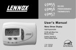
1
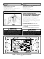
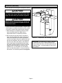
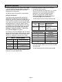
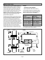
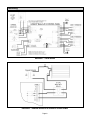
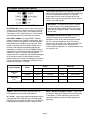
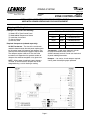
ZONING SYSTEM
Litho U.S.A.
© 2004 Lennox Industries Inc.
Dallas, Texas, USA
504,926M
5/2004
LZP-2
ZONE CONTROL PANEL
INSTALLATION INSTRUCTIONS FOR ZONE CONTROL PANELS
USED WITH LENNOX HEATING AND COOLING EQUIPMENT
Shipping & Packing List
Package 1 of 1 contains the following:
TABLE 1 – TRANSFORMERS
(1) Model LZP-2 Zone Control Panel
(1) Model 88K38 Temperature Sensor
(1) Installation Instructions
(1) Owners Manual
(1) Warranty Card
Required Components (ordered separately):
24 VAC Transformer – The size of the transformer
needed is determined by the total power requirements
for the control panel, thermostats and dampers. The
control panel and thermostats together require 10VA.
The dampers require 10VA each. The size of the
transformer will depend on the greatest number of
dampers that could be energized at any given time.
NOTE – When power closed/spring open dampers
are used, at least one zone’s dampers will not be
energized during a call for heating or cooling.
Part Number
Size
Voltage Description
10P17
40VA
120/208/240V-24V
10P87
50VA
120/208/240V-24V
12P61
75VA
120/208/240V-24V
83P74
4" Square Electrical Box
Thermostats – single-stage, electronic, 24-volt
heat/cool thermostats which include a “C”
(24VAC common) terminal. Do not use mechanical
or power robbing thermostats.
Dampers – 2 or 3-wire, 24-volt dampers required.
2-wire, power closed/spring open preferred.
FIGURE 1 – LENNOX® MODEL LZP-2 CONTROL PANEL LAYOUT
Page 1
Application
Features
• Two zones
• Single-stage electric or gas furnace
• Single-stage air conditioner
• Multi-stage equipment can be used provided that it
stages on it’s own internal controls
• Not applicable to heat pump systems
• Adjustable high and low discharge air temperature limits
• ON/OFF duct air purge control
• LED indicators for outputs
• Time Delay Override
• 2 or 3-wire damper compatibility
Installation
• Install the control panel indoors only.
• Do not install the control panel where the temperature will exceed 140°F or will drop below 32°F.
• Do not install the control panel on foundation
walls, HVAC equipment or duct system where
moisture may condense on the enclosure.
• Do not install the control panel in a room where it
will be exposed to elevated humidity levels such
as a laundry room.
1. Remove the cover. Replace the cover when
installation is complete.
2. There are eight slots on the base of the enclosure
(see Figure 2).
The above illustration shows a typical two zone control system.
3. Use #8 screws (field supplied) to install the base.
WARNING
CAUTION
Improper installation, adjustment, alteration,
service or maintenance can cause property
damage, personal injury or loss of life. Installation
and service must be performed by a qualified
installer, service agency or the gas supplier.
Electrostatic discharge can damage the control.
Touch a grounded metal object before touching
the circuit board, and then only touch the circuit
board on the edges when handling.
NORMAL
FLASHING
D4
D8
+
+
C6
R
NO
+
R12
R10
C5
D12
J1
G
D9
U1
RV1
D13
C7
D14
+
R17
K4
R14
R13
R11
Q1
R15
R16
C
U3
C8
K2
U4
D15
R19
DamperZ1
R20
D17
D18
U5
R22
F1
C13
J5
R
R25
R24
D22
G
R
NO
C17
C16
C15
+
F2
D23
R36
U6
C12
K5
R31
R32
R33
R34
NC
R45
LENNOX
X3785 REV. 1
LZP-2
ELECT.
NoPURGE
HT-160
CL-45
140
R37
R38
R39
R40
40
C19
C20
C21
C22
RV7
GAS
PURGE
R46
RV8
C18
C
R42
DAS
R44
R47
RV6
R43
R41
R35
MAIN FUSE
J4
W
D24
DamperZ2
FIGURE 2 – CONTROL PANEL AND ENCLOSURE BASE
Page 2
Y
R27
R29
D21
R30
SPARE FUSE
C
R26
C14
Y1
R28
D20
+
24VAC
ZONE 2
C11
U2
R21
TDO
J3
D19
R23
+
SW1
TP4
C10
D16
RV5
RV4
W
RV3
R18
K3
NC
RV2
D11
C9
Y
R9
D6
D10
K1
RC
RH
J2
R7
D7
C3
Y
C4
R1
Y
D5
R6
ZONE 1
C2
5VDC
R8
C1
G
R5
R2
GND
24VDC
+
W
G
+
W
D1
D3
R4
R3
D2
EQUIP.
(8) Mounting
Slots
Installation (continued)
4. Install and Wire the Discharge Air Temperature Sensor
CAUTION
As with any mechanical equipment, personal injury
can result from contact with sharp sheet metal
edges. Be careful when you handle this equipment.
15"
CAUTION
D/3
D
Before attempting to perform any service or
maintenance, turn the electrical power to unit OFF
at disconnect switch.
W
FRONT
The tip of the sensor must be located in a region of fully
mixed supply of air before the take-offs (not in a dead
air space) in order for the system to work correctly.
a. Wire discharge air temperature probe to control
panel using thermostat wire. Note that the
temperature sensor is not polarity sensitive.
b. Be sure that the tip of the sensor is located at
least 15 inches downstream from the leaving air
side of the evaporator in the discharge plenum,
and 1/3 of the depth (D/3) of the plenum (D) from
the front of the plenum (the front is the side with
the furnace or CB access doors), and centered
side to side. Move the adjustable bracket along
the length of the discharge air sensor to achieve
proper sensor tip location (tip of sensor to be
located at W ÷ 2). The sensor can be inserted
from any side of the plenum, as long as the tip of
the sensor is in the correct position. See Figure 3.
FIGURE 3 – DISCHARGE AIR SENSOR LOCATION
Page 3
IMPORTANT: The discharge air sensor is required.
If a short or open circuit is detected between the
Plenum Sensor terminals, the control panel will only
respond to Zone 1 and the dampers will stay in the
open position.
Installation (continued)
5. Install the required transformer selected from Table 1
– DO NOT USE the HVAC equipment transformer to
power the control panel. Refer to the instructions
provided with the transformer.
6. Install the thermostats. Refer to the instructions
provided with the thermostat.
Any 24-volt electronic thermostat with a “C” (24 VAC
common) terminal can be used. Power robbing
thermostats can cause unintended operation –
DO NOT use mechanical or power robbing
thermostats. Table 2 lists the required terminals
and recommended Lennox thermostats:
18 AWG thermostat wire minimum recommended.
Sizing the Transformer:
The system requires approximately 10 VA for the
control panel and thermostats and 10 VA for each
damper. The size of the transformer will depend on the
greatest number of dampers that could be energized
at any given time (at least one zone’s dampers will not
be energized during a heating or cooling call when
using power close, spring open dampers). The size of
the transformer must not exceed 75VA. If the value is
greater than 75VA, some dampers will need to be
powered by a separate transformer – refer to Field
Wiring Damper Diagram 2 on page 6.
18 AWG thermostat wire minimum recommended.
TABLE 2 – THERMOSTAT REQUIREMENTS
Type
Terminals
HEAT/COOL R, C, W, Y, G
For instance, if you have 3 dampers, then you would
require 10VA for the system, 20VA (10VA X 2) for the
dampers for a total of 30VA, so catalog number 10P17
would be an adequate transformer size at 40VA.
TABLE 1 – TRANSFORMERS
Recommended
Thermostat
• SignatureStat 1H/1C
(51M26)
• Elite 1H/1C (49M55)
Thermostat Terminal
Function
R
24 VAC Hot
C
24 VAC Common
W
Heat
Part Number
Size
Voltage Description
Y
Cool
10P17
40VA
120/208/240V-24V
G
Fan
10P87
50VA
120/208/240V-24V
12P61
75VA
120/208/240V-24V
83P74
7. Install the dampers. Refer to the instructions provided
with the damper.
4" Square Electrical Box
18 AWG thermostat wire minimum recommended.
The transformers listed in this chart include a plate
mount for a 4" square electrical box.
Page 4
Bypass Damper Sizing
When fewer than the maximum number of zones are
calling for heating or cooling, an excess volume of air is
delivered, and because of the excess air, an excess
amount of static pressure is produced as well. Zone
systems often require a bypass duct to relieve this
pressure. A properly sized barometric bypass damper
must be installed in the bypass duct which is run
between the supply and return air duct systems (see
Figure 4). The barometric damper and the bypass duct
must be sized to accommodate the excess static
pressure from the supply duct.
Example:
The bypass tap in the return air duct must be at least
6 ft. from the furnace /air handler to ensure that the hot
or cold air coming off of the plenum has time to mix
with the return air before it passes through the air
handler again. The provided discharge air sensor will
prevent any damage to the equipment from overheating
or coil freeze-up by interrupting the HVAC equipment.
Round
Rectangular
8 in. dia. – 400 cfm
12 x 8 – 1000 cfm
10 in. dia. – 750 cfm
12 x 10 – 1200 cfm
12 in. dia. – 1200 cfm
12 x 12 – 1400 cfm
14 in. dia. – 1800 cfm
20 x 8 – 1600 cfm
The bypass damper and duct should be sized to handle
the excess pressure created when the smallest zone is
operating alone (worst case). To size the bypass
damper, subtract the total air volume capacity of the
smallest zone from the total air volume of the system.
16 in. dia. – 2400 cfm
20 x 10 – 2000 cfm
ZONE 1
THERMOSTAT
Total System air volume: 2000 cfm
Air volume of smallest zone: 600 cfm
Bypass requirement: 2000 - 600 = 1400 cfm
In this example, the bypass duct should be sized to
handle the 1400 cfm excess pressure created when
only the smallest zone has a demand. For bypass
damper air volume capacities, see Table 3.
TABLE 3
20 x 12 – 3000 cfm
Refer to the parts and supplies catalog for information
on available barometric bypass dampers.
BYPASS
DAMPER
ZONE 1
BYPASS DUCT
ZONE
DAMPER
SUPPLY
AIR
HEATING/
COOLING
UNIT
RETURN
AIR
DISCHARGE
AIR SENSOR
ZONE
DAMPER
6 ft. (1.8 m)
ZONE 2
THERMOSTAT
ZONE 2
TRANSFORMER
FOR
DAMPERS,
PANEL AND
THERMOSTATS
FIGURE 4 – BYPASS DAMPER INSTALLATION
Page 5
ZONE
CONTROL
PANEL
Field Wiring
DIAGRAM 1 – FIELD WIRING
DIAGRAM 2 – DAMPER WIRING WITH SEPARATE TRANSFORMER
Page 6
Pin Jumper Settings (see Figure 5)
DISCHARGE AIR SENSOR HT-140/160: This jumper
controls the temperature at which the heating equipment
will cut out to prevent overheating. For a high limit
temperature of 140°F, move the jumper to the “140”
position. For a high limit temperature of 160°F, leave the
jumper in the “160” position.
IMPORTANT: The temperature sensor is required.
If a short or open circuit is detected between the
Discharge Air Sensor (DAS) terminals, the control
panel will only respond to Zone 1 and the dampers
will not close.
FIGURE 5 – PIN JUMPER SETTINGS
ELECTRIC/GAS: If electric heat is to be used, move the
jumper to the “ELECT” position. This will turn on the fan
(G output terminal) with a heat call (W output terminal).
If the jumper is in the “GAS” position, it is assumed that
the heating equipment will control the fan operation.
NO PURGE / PURGE: If the NO PURGE / PURGE
jumper is moved to the “PURGE” purge position, the G
terminal will remain energized for a one minute purge
delay following the completion of a cooling call. If the
jumper is moved to the “NO PURGE” position, the G
terminal will de-energize immediately following the
completion of a cooling call. The NO PURGE setting is
designed for use with systems where the furnace or air
handler has a built in fan purge. The NO PURGE
damper hold time is longer than the PURGE setting due
to the Lennox furnaces installer settable maximum
blower off delay of 3 minutes. The following chart details
the zone panel outputs and damper hold times when a
heating or cooling call is satisfied:
Jumper Settings
Mode
Heat/Cool
Gas
Heat/Cool
Elect.
1
DISCHARGE AIR SENSOR CL-45/40: This jumper
controls the temperature at which the cooling
equipment will cut out to prevent freezing the indoor
coil. For a low limit temperature of 45°F, leave the
jumper in the “45” position. For a low limit temperature
of 40°F, move the jumper to the “40” position. To
maintain optimum operation, it is recommended to leave
this setting at “45”.
Purge
No Purge
Output
Damper Hold Time
Output
Damper Hold Time
Cooling
G
1 minute
No G,
3-1/2 minutes
Heating
No G
1 minute
No G,
3-1/2 minutes
Cooling
1
G
1 minute
No G,
3-1/2 minutes
Heating
G1
1 minute
No G,
3-1/2 minutes
1
The G terminal will remain energized for 1 minute.
LEDs
POWER – Blinks during normal operation. Starts to
blink approximately 6 seconds after power up.
G, Y and W – Lights when respective equipment outputs
are energized. The W LED will flash if the heating high
temperature limit has been reached. The Y LED will flash
if the cooling low temperature limit has been reached.
ZONE 1 Damper and ZONE 2 Damper – Lights when
the Normally Open (NO) damper terminal for that zone
is energized (i.e. LEDs show which zones are NOT
receiving conditioning when the HVAC equipment is
operating).
Page 7
Sequence of Operation
A Time Delay Override (TDO) button is available on the
control panel to speed up the internal timer by a factor
of 60 for system checkout. One second of holding down
the button relates to one minute of speed up time in the
control.
HEATING AND COOLING EQUIPMENT OPERATION
Heating Operation
When a zone makes a call for Heat, the W output
terminal will energize. The G terminal will also energize
if the ELECTRIC/GAS jumper is in the ELECT position.
The W terminal de-energizes when (1) all zones stop
calling for Heat, (2) the call has exceeded the heat/cool
changeover time limit while a cooling call exists or (3)
the call is interrupted by the high limit setting. When the
W terminal is de-energized, a minimum off time delay of
4 minutes must elapse before it can be energized again.
Fan Purge Time Delay
If the ELECTRIC/GAS jumper is in the ELECT
position and the PURGE/NO PURGE jumper is in the
PURGE position, the G terminal will remain energized
for one minute after the W terminal is de-energized.
The NO PURGE setting is the preferred purge control
setting for Lennox equipment. Lennox equipment
includes controls which sequence the indoor fan off
after a call for heat has been satisfied.
Heat/Cool Changeover: When a call for heating or
cooling exists and an opposing call is made from
another zone, a 20 minute timer is activated. If the
original call is not satisfied within that 20-minute time
period, the call will be interrupted, turning the equipment
off and allowing for the normal fan purge cycle and
minimum equipment off time. The opposing call will then
be answered. After 20 minutes, if the original call still
exists, the opposing call will be interrupted and the
original call can once again be recognized.
High/Low Limit Temperature: The high/low limit
temperature settings are designed to prevent the heat
exchanger from overheating or the cooling coil from
freezing. The temperature sensor in the supply duct
senses the discharge air temperature and interrupts the
heating/cooling equipment (depending on the Heat and
Cool temperatures set on the control panel) before
overheating/freezing occurs. When a heating/cooling
call is interrupted by the high/low temperature limit, the
zone control panel turns the equipment off and
energizes the G terminal (if not already energized). The
W or Y LED on the control panel will flash during a
high/low limit temperature interrupt. Once the
temperature drops/rises 10°F and the minimum off time
has expired, the equipment is turned back on if the call
for conditioning still exists. The Heating/Cooling LED will
stop flashing.
If the ELECTRIC/GAS jumper is set in the GAS
position, the G terminal does not turn on during purge
regardless of the position of the PURGE or NO
PURGE switch. Lennox furnaces will control the
purge though the furnace control board cool down
feature. The cool down time is often adjustable at the
furnace control board up to 3.5 minutes. NO PURGE
is the preferred method of purge when this zone
panel is applied to Lennox equipment.
Cooling Operation
When a zone makes a call for Cooling, the Y and G
terminals will energize. The Y terminal de-energizes
when (1) all zones stop calling for Cooling, (2) the call
has exceeded the heat/cool changeover time limit while
a heat call exists or (3) the call is interrupted by the low
limit temperature setting. When the Y terminal is deenergized, a minimum off time delay of 4 minutes must
elapse before it can be energized again.
Fan Purge Time Delay
If the PURGE/NO PURGE jumper is in the PURGE
position, the G terminal will remain energized for one
minute after the Y terminal is de-energized. If the
jumper is in the NO PURGE position, the G terminal
will de-energize immediately.
Page 8
IMPORTANT: Should a short or open circuit be
detected across the DAS terminals, the zone system
will respond only to Zone 1 and the dampers will
not energize.
Sequence of Operation (continued)
CONTINUOUS FAN OPERATION
A call for Fan from any zone will initiate the G
equipment output terminal. The normally open (NO)
damper terminal at all zones not calling for continuous
fan will be energized.
DAMPER OPERATION
The “NO” output will be energized and the “NC” output
will be de-energized for any zone not calling for heating
or cooling while the equipment output is energized and
during the damper purge time delay. During equipment
operation or during the damper purge time delay,
should all zones stop calling for heating or cooling, the
damper terminals will remain in the position they were
in before all zones stopped calling.
Damper Purge Time Delay
When the Purge/No Purge jumper is at No Purge,
the damper purge time delay is 3.5 minutes and
begins when the equipment output(s) turn off. NO
PURGE is the preferred method of purge control for
Lennox furnaces and air conditioners. When the
jumper is at Purge, the damper purge time delay is
one (1) minute.
Page 9
Troubleshooting
DETECTING HVAC SYSTEM PROBLEMS
Symptom
Possible Solution
Pressure switch open.
Consult condensing unit manual for possible cause.
Condensing unit receiving signal but will not turn on.
Compressor is off due to internal overload protector.
Consult condensing unit manual for possible cause.
Condenser control board anti short cycle timer is not
yet expired. Most anti short cycle timers are 5 minutes
or less, if the unit does not start after 5 minutes consult
the condensing unit manual for possible causes.
Furnace tripped the primary limit, but the
zone panel does not indicate that the discharge
air limit has been exceeded.
A high static condition exists. Move the sensor
further down stream to sense air that has mixed more
thoroughly. Be sure not to place the senor past
the take offs. High static pressure must be corrected.
Bypass tap is too close to inlet of air handler.
Adjust bypass tap in the return air duct so that is further
away from the furnace. This will give the air more of a
chance to be tempered with room return air before
entering the air handler again.
Limit on furnace open. Check position of DAS in
the plenum and move further down stream if possible.
High static condition must be corrected.
Air handler receiving signal but will not turn on.
DAS limit jumper needs to be moved to a lower setting.
Trouble shoot air handler – see air handler
documentation.
Page 10
Troubleshooting (continued)
DETECTING HEATING, COOLING AND FAN PROBLEMS
Symptom
Possible Solution
Nothing comes on.
No power to control panel. Green “Normal Flashing”
LED should be blinking, if not apply power to
24VAC inputs of control panel. Check fuse.
Single transformer system. Install jumper between RC
and RH at HVAC Equipment outputs of control panel.
Interlock switch on furnace is open – close access doors.
Thermostat is not calling for heat. Check voltage at
the thermostat W input on the control panel.
Heat will not come on.
Zone 2 calling while open or short at DAS inputs is
causing control panel to respond only to Zone 1.
Thermostat is power robbing or mechanical. Only use
line powered electronic thermostat with a C terminal.
Single transformer system. Install jumper between RC
and RH at HVAC equipment outputs of control panel.
Thermostat is not calling for cooling. Check voltage
at the thermostat Y input on the control panel.
Thermostat could be invoking a timed off delay.
Cooling will not come on.
Zone 2 calling while open or short at DAS inputs is
causing control panel to respond only to Zone 1.
Zone panel could be invoking a timed off delay.
Thermostat is power robbing or mechanical. Only use
line powered electronic thermostat with a C terminal.
Check if G is energized at the zone panel.
Fan will not come on.
Check if G is energized at the thermostat.
Check if G is energized at the air handler.
Dampers do not position on a call for heating,
cooling or fan. Heat, cooling or fan will not come on
when the Zone 2 thermostat is calling.
System requires the Discharge Air sensor. If DAS is not
installed, only Zone 1 calls will be recognized and dampers
will not operate. Disconnect power to the control panel,
install the DAS and restore power to the control panel.
Fan immediately comes on with heat call.
ELECT/GAS jumper set to ELECT – change setting
to GAS.
After a cool call, the fan stops then starts right
away only to stop a short while later.
HVAC system has built in duct purge. Set PURGE/NO
PURGE jumper on control panel to NO PURGE.
Fan is running but no heat, and W LED is blinking.
Discharge air temperature exceeds set limit.
Allow discharge air to cool 10° below set limit and
allow timed off delay to expire.
Fan is running but no cooling, and Y LED is blinking.
Discharge air temperature dropped below set limit.
Allow discharge air to warm 10° above set limit and
allow timed off delay to expire.
Both the Y and W LEDs are blinking.
An open or short in the DAS sensor has been detected.
Install or repair the sensor.
Page 11
Troubleshooting (continued)
DETECTING DAMPER PROBLEMS
Symptom
Possible Solution
DAS shorted or open causing the panel to only respond
to zone 1 inputs while not closing any dampers.
Damper opens when it should be closed.
Damper will not close.
Damper wired incorrectly. Spring open power close
dampers should be connected between NO and
C terminals.
DAS shorted or open causing the panel to only respond
to zone 1 inputs while not closing any dampers.
Damper motor faulty.
CHECKING THERMOSTAT VOLTAGES
Using a digital voltmeter (DVM) measure the AC voltage supplied at the R and C terminals of the Thermostat
inputs on the control panel for the zone in question. This voltage should be same as the voltage supplied to the
control panel 24VAC terminals. Make a call for heat, cooling or fan. Measure the voltage across the terminal that
should be energized (i.e. W for heat, Y for cooling, etc.) and the C terminal. This should be the same voltage as
there is between the R and C terminals. Measure the voltage across a terminal that should NOT be energized
and the C terminal; this voltage should be zero.
DISCHARGE AIR SENSOR CHECKOUT
The discharge air sensor is a temperature dependent resistor; the higher the temperature, the lower the
resistance. In order to confirm the sensor is working, both sensor leads must be disconnected from the zone
panel board. Using a digital voltmeter (DVM) set to read resistance, touch the leads from the sensor to the
probes of the DVM. Take care not to create a parallel resistance path through your body by touching both probes
with your fingers or a faulty reading will be obtained. At 77F, the resistance of the sensor will be 10K ohm. If the
sensor is cooler than 77F, the resistance will be higher, if it is warmer, the resistance will be lower. After reading
the resistance at room temperature, warm the tip of the sensor by holding it in the palm of your hand, and take
another resistance reading. This reading should be noticeable lower than the room temperature reading.
Temperature (°F)
65
70
75
80
85
90
Resistance (ohms)
13476
11884
10501
9298
8249
7333
The zone panel is well equipped to monitor the operation of the probe and determine if a failure has occurred.
The probe should be considered an integral (but replaceable) part of the zone panel. The zone panel will indicate
if the probe is operating improperly and needs to be replaced.
B2203458
10006259
Page 12