1
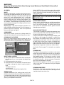
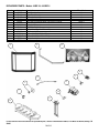
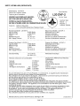
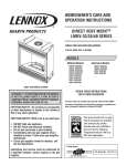
INSTALLATION AND OPERATION MANUAL FREESTANDING VENTED GAS FIRED ROOM HEATERS L20 DVF-2 shown with optional gold door and brickaded interior Models: L20 BF-2 (B-Vent) and L20 DVF-2 (Direct-Vent) RETAIN THIS MANUAL FOR FUTURE REFERENCE P/N 775,021M Rev. C, 8/04 Report #189122-1027389 Model L20 DVF-2 may be installed in an aftermarket permanently located, manufactured (mobile) home, where not prohibited by local codes WARNING: IF THE INFORMATION IN THIS MANUAL IS NOT FOLLOWED EXACTLY, A FIRE OR EXPLOSION MAY RESULT CAUSING PROPERTY DAMAGE, PERSONAL INJURY OR LOSS OF LIFE. AVERTISSEMENT: ASSUREZ-VOUS DE BIEN SUIVRE LES INSTRUCTIONS DONNÉ DANS CETTE NOTICE POUR RÉDUIRE AU MINIMUM LE RISQUE D’INCENDIE OU POUR ÉVITER TOUT DOMMAGE MATÉRIEL, TOUTE BLESSURE OU LA MORT. FOR YOUR SAFETY: Do not store or use gasoline or other flammable vapors or liquids in the vicinity of this or any other appliance. POUR VOTRE SÉCURITÉ: Ne pas entreposer ni utiliser d’essence ni d’autre vapeurs ou liquides inflammables dans le voisinage de cet appareil ou de tout autre appareil. FOR YOUR SAFETY: What to do if you smell gas: POUR VOTRE SÉCURITÉ: Que faire si vous sentez une odeur de gaz: • DO NOT light any appliance. • DO NOT touch any electrical switches. • Do not use any phone in your building. • Immediately call your gas supplier from a neighbor’s phone. Follow your gas suppliers instructions. • If your gas supplier cannot be reached, call the fire department. • Ne pas tenter d’allumer d’appareil. • Ne touchez à aucun interrupteur. Ne pas vous servir des téléphones se trouvant dans le batiment où vous vous trouvez. • Evacuez la piéce, le bâtiment ou la zone. • Appelez immédiatement votre fournisseur de gaz depuis un voisin. Suivez les instructions du fournisseur. • Si vous ne pouvez rejoindre le fournisseur de gaz, appelez le service dos incendies. Installation and service must be performed by a qualified installer, service agency or the gas supplier. L’installation et service doit être exécuté par un qualifié installeur, agence de service ou le fournisseur de gaz. IMPORTANT WARNINGS / CAUTIONS CAUTION: READ THIS MANUAL THOROUGHLY BEFORE STARTING INSTALLATION. FOR YOUR SAFETY, FOLLOW THE INSTALLATION, OPERATION AND MAINTENANCE INSTRUCTIONS EXACTLY WITHOUT DEVIATION. FAILURE TO FOLLOW THESE INSTRUCTIONS MAY RESULT IN A POSSIBLE FIRE HAZARD AND MAY VOID THE WARRANTY. IF THIS APPLIANCE IS NOT PROPERLY INSTALLED, A HOUSE FIRE MAY RESULT. CONTACT LOCAL BUILDING OR FIRE OFFICIALS ABOUT RESTRICTIONS AND INSTALLATION INSPECTION IN YOUR AREA. 1. WARNING: IMPROPER ASSEMBLY, INSTALLATION, ADJUSTMENT, ALTERATION, SERVICE OR MAINTENANCE CAN CAUSE INJURY AND / OR PROPERTY DAMAGE. INSTALLATION AND SERVICE MUST BE PERFORMED BY A QUALIFIED INSTALLER, SERVICE AGENCY OR THE GAS SUPPLIER. EXCEPT WHEN COMPLYING WITH LOCAL CODES, ANY DEVIATION FROM THE INSTALLATION AND / OR OPERATING INSTRUCTIONS CONTAINED IN THIS MANUAL WILL VOID THE APPLIANCE WARRANTY AND MAY BE HAZARDOUS. 2. DUE TO HIGH TEMPERATURES, THIS APPLIANCE SHOULD BE LOCATED OUT OF TRAFFIC AND AWAY FROM FURNITURE, DRAPERIES AND NOT IN WINDY OR DRAFTY AREAS. 3. THE APPLIANCE MUST NOT BE CONNECTED TO A CHIMNEY FLUE SERVING A SEPARATE SOLID-FUEL BURNING APPLIANCE. 4. MODEL L20 DVF-2 IS EQUIPPED WITH A RELIEF DOOR IN CASE OF DELAYED IGNITION BLOWBACK. IF THE RELIEF DOOR OPENS, REMOVE BACK PANEL AND INSPECT FOR GASKET DAMAGE. IF NECESSARY, REPLACE WITH FACTORY SUPPLIED GASKET ONLY. CONFIRM RELIEF DOOR IS CLOSED AND PROPERLY SEATED, THEN REPLACE BACK PANEL. 5. CAUTION: HOT WHILE IN OPERATION. AN APPLIANCE HOT ENOUGH TO WARM YOUR HOME CAN SEVERELY BURN ANYONE TOUCHING IT. KEEP CHILDREN, CLOTHING AND FURNITURE AWAY. CONTACT MAY CAUSE SKIN BURNS. DO NOT LET CHILDREN TOUCH THE APPLIANCE. TRAIN THEM TO STAY A SAFE DISTANCE FROM THE UNIT. 6. DO NOT PLACE CLOTHING OR OTHER FLAMMABLE MATERIAL ON OR NEAR THE GAS APPLIANCE. THE MINIMUM CLEARANCES MUST BE MAINTAINED FOR ALL COMBUSTIBLE SURFACES AND MATERIALS INCLUDING; FURNITURE, CARPET, DRAPES, CLOTHING, WOOD, PAPERS, ETC. 7. NEVER SEAL THE OPENING AT THE REAR OF THE STOVE. 8. DO NOT CONNECT 110-12 VAC (RESIDENTIAL LINE VOLTAGE) TO THE GAS CONTROL VALVE OR CONTROL WIRING SYSTEM OF THE UNIT. 9. ANY SAFETY SCREEN OR GUARD REMOVED FOR SERVICING MUST BE REPLACED PRIOR TO OPERATING THE APPLIANCE. 10. WARNING: USE ONLY THE GLASS DOOR CERTIFIED WITH THIS APPLIANCE. EXERCISE CAUTION TO PROTECT GLASS FROM IMPACT. DO NOT OPERATE THE APPLIANCE WITH BROKEN GLASS OR USE SUBSTITUTE MATERIALS. 11. DO NOT USE THIS APPLIANCE IF ANY PART HAS BEEN UNDER WATER. IMMEDIATELY CALL A QUALIFIED SERVICE TECHNICIAN TO INSPECT THE APPLIANCE AND REPLACE ANY PART OF THE CONTROL SYSTEM AND GAS CONTROL WHICH HAS BEEN UNDER WATER. 12. DO NOT BURN WOOD OR OTHER MATERIAL IN THIS HEATER. 13. WARNING: THE APPLIANCE AREA MUST BE KEPT CLEAR AND FREE FROM COMBUSTIBLE MATERIALS, GASOLINE AND OTHER FLAMMABLE VAPORS AND LIQUIDS. 14. DO NOT USE A BLOWER INSERT, HEAT EXCHANGER INSERT OR OTHER ACCESSORY NOT APPROVED FOR USE WITH THIS APPLIANCE. 15. THIS APPLIANCE IS NOT FOR USE WITH AIR FILTERS. 16. ANY CHANGE TO THIS HEATER OR ITS CONTROLS CAN BE DANGEROUS. 17. THIS APPLIANCE SHOULD BE INSPECTED AND MAINTAINED AT LEAST ANNUALLY BY A PROFESSIONAL SERVICE PERSON. MORE FREQUENT CLEANING MAY BE REQUIRED DUE TO EXCESSIVE LINT FROM CARPETING, BEDDING MATERIAL, ETC. IT IS IMPERATIVE THAT CONTROL COMPARTMENTS, BURNERS AND CIRCULATING AIR PASSAGEWAYS OF THE APPLIANCE BE KEPT CLEAN. 18. THIS APPLIANCE IS ONLY FOR USE WITH THE TYPE OF GAS INDICATED ON THE RATING LABEL (LOCATED INSIDE CONTROL PANEL). THIS APPLIANCE IS NOT CONVERTIBLE FOR USE WITH OTHER FUEL UNLESS A CERTIFIED KIT IS USED. 19. CAUTION: UNDER NO CIRCUMSTANCES SHOULD THESE APPLIANCES BE VENTED TO OTHER ROOMS OR BUILDINGS. THESE APPLIANCES MUST ONLY BE VENTED TO THE OUTSIDE. VENT TERMINATIONS SHALL NOT BE RECESSED INTO A WALL OR SIDING. 20. WARNING: THESE APPLIANCES MUST BE PROPERLY CONNECTED TO A VENTING SYSTEM. OPERATION OF THESE GAS APPLIANCES WHEN NOT CONNECTED TO A PROPERLY INSTALLED AND MAINTAINED VENTING SYSTEM CAN RESULT IN CARBON MONOXIDE (CO) POISONING AND POSSIBLE DEATH. 21. WARNING: DO NOT MODIFY THE VENTING SYSTEM, APPLIANCE, OR CONTROLS IN ANY WAY. BE ADVISED, ANY MODIFICATION CAN BE DANGEROUS. 22. IMPORTANT: DO NOT EXCEED THE MAXIMUM HORIZONTAL RUNS ALLOWED. 23. SAVE THESE INSTRUCTIONS. PAGE 2 TABLE OF CONTENTS Important Warnings ........................................................ 2 CONGRATULATIONS ON THE PURCHASE OF YOUR NEW GAS APPLIANCE MANUFACTURED BY LENNOX HEARTH PRODUCTS. Testing / Listing, Using this Manual ................................. 3 Planning Your Installation ..............................................4-6 When you purchased your new gas fired heater, you joined the ranks of thousands of concerned individuals whose answer to their home heating needs reflects their concern for aesthetics, efficiency and our environment. We extend our continued support to help you achieve the maximum benefit and enjoyment available from your new gas fired heater. Manufactured (Mobil) Home Requirements....................... 6 Installation ...................................................................7-15 Care and Operation.....................................................16-17 Propane Conversion ...................................................18-19 It is our goal at Lennox Hearth Products to provide you, our valued customer, with an appliance that will ensure you years of trouble free warmth and pleasure. Maintenance ...............................................................20-21 Wiring Diagrams ............................................................. 22 Thank you for selecting a Lennox Hearth Products gas fired heater as the answer to your home heating needs. Troubleshooting .........................................................23-24 Replacement Parts / Optional Accessories....................... 25 Sincerely, All of us at Lennox Hearth Products Specifications .............................................................27-28 Safety / Listing Labels ................................................29-30 Ownership Record and Service Log................................. 31 PACKAGING LIST This appliance is packaged with an accessory package, which contains the following: TESTING / LISTING This appliance is tested and certified as safe for residential use by an internationally recognized testing and certification agency. The safety tests are conducted in accordance with American National Standards Institute (ANSI) requirements. These appliances are tested, certified, and listed by the CSA, AGA, CGA to ANSI Z21.88a - 2003 Vented Gas Fireplace Heaters and CSA 2.33a - M98 - 2003 Vented Gas Fireplace Heaters. One One One One One - Installation and operation instructions manual. Warranty. Log set and embers. LP conversion kit. 9 ft. electrical power cord. USING THIS MANUAL APPROVED VENTING: Please read and carefully follow all of the instructions found in this manual. Please pay special attention to the safety instructions provided in this manual. Following the Homeowner’s Care and Operation Instructions included here will assure that you have many years of dependable and enjoyable service from your appliance. L20 DVF-2 Listed for installation with Security Secure Vent chimney or Simpson Dura Vent brand chimney only. Other brands may not be used. See pages 8 and 9. L20 BF-2 May be vented with any listed class B chimney components installed in accordance with manufacturers instructions. See page 11. PAGE 3 PLANNING YOUR INSTALLATION GAS PRESSURE (WC = Water Column) Minimum inlet gas supply pressure for the purpose of input adjustment: LOCAL AND NATIONAL CODE REQUIREMENTS The installation of these appliances must conform with local codes or, in the absence of local codes, with the National Fuel Gas Code, (for USA) NFPA 54 / ANSI Z223.1 - latest edition. Natural Gas - 4.5” WC min. – 7.0” WC max. Propane (LP) - 11” WC min - 13.0” WC max. Air Circulation Blower: The blower electrical power cord must be electrically grounded per local codes or per electrical codes: In USA, NEC, ANSI / NFPA 70 - latest edition. In Canada, CSA C22.1 Manifold gas supply pressure: LOW HIGH Natural Gas - 1.8” + / -.3” WC (to) 3.5” + / -.3” WC 17,000 BTU / hr 26,000 BTU / hr WARNINGS ELECTRICAL GROUNDING INSTRUCTIONS. THIS APPLIANCE IS EQUIPPED WITH A THREE-PRONG (GROUNDING) PLUG FOR YOUR PROTECTION AGAINST SHOCK HAZARD AND SHOULD BE PLUGGED DIRECTLY INTO A PROPERLY GROUNDED THREE-PRONG RECEPTACLE. DO NOT CUT OR REMOVE THE GROUNDING PRONG FROM THIS PLUG. Propane (LP) 6.6” + / -.3” WC 17,000 BTU / hr (to) 10” + / -.3” WC 24,000 BTU / hr Note: ” WC = Inches Water Column PRESSURE TAPS Gas Inlet Pressure Tap - Located on bottom left of gas valve. WARNING: TO AVOID ELECTRICAL SHOCK, ALWAYS ENSURE THAT THE POWER CORD IS UNPLUGGED (I.E., THERE IS NO ELECTRICAL POWER TO THE CIRCULATION BLOWER) BEFORE HANDLING THE CIRCULATION BLOWER OR PERFORMING ANY WORK ON THE APPLIANCE. Gas Outlet (manifold) pressure tap - Located on bottom right of gas valve. Gas Control Valve Pilot Adjustment Screw Gas Control Knob Convertible HI/LO Regulator Regulator Cap High Altitude: Gas inputs shown are for elevations up to 4500 feet. For elevations above 4500 feet, contact your gas supplier or qualified service technician regarding the necessary deration of appliance (deration: replacing burner orifice with a smaller one to reduce input). Ratings must be reduced at the rate of 4 percent for each 1,000 feet above sea level. Refer to (for USA) NFPA 54 / ANSI Z223.1 - latest edition for orifice resizing. Piezo Igniter TOOL / EQUIPMENT LIST The following tools and equipment are recommended for completing the partial assembly required when the appliance is installed: • • • • • • • Inlet Pressure Tap Wiring Terminals Outlet Pressure Tap Pressure Testing: See Pressure Testing on page 12. 7/16”, 3/4” open end wrenchs. 1/4”, 3/8” nut drivers. Pipe wrench. Phillips head screw driver. Flat head screw driver. Pipe sealant compound. Leak test fluid “U” tube manometer or pressure gauge (0 - 16” (inches water column) H2O scale. PAGE 4 PLANNING YOUR INSTALLATION QUESTIONS TO ASK THE LOCAL BUILDING OFFICIAL 5. In some states or municipalities, a licensed gas fitter or plumber may be required to install this appliance. Check with your local building official for requirements in your area (i.e. Is a license required for installation of gas supply line)? Correct installation is critical and imperative for reducing fire hazards and perilous conditions that can arise when gas appliances function improperly. The appliance must be installed per manufacturers’ instructions. 6. Gas appliance equipment and installations must conform to appropriate local codes and applicable state and federal requirements. Familiarity with these requirements before installation is essential. Important considerations to discuss with local building officials include: Maximum amount of gas pipe without a pressure test type of test required? 7. Are below grade penetrations of the gas line allowed? 8. Is concealed gas piping allowed? 1. Applicable codes (i.e. Uniform Mechanical Code, State or Regional Gas Codes, National Fuel Gas Code)? 9. Specific requirements of concealed fittings? 10. Is rigid pipe to appliance required? 2. Local amendments? 11. Allowed piping materials? 3. Recognized testing lab: CSA / AGA. 12. Shut-off valve required within 4 feet of the firebox? 4. Is a permit required - cost? 13. May the shut-off valve be concealed? 14. Rooms where the installation is not allowed? In the absence of local codes, installation should conform to the National Fuel Gas Code, also known at ANSI Z223.1NFPA 54. PAGE 5 PLANNING YOUR INSTALLATION Rear Wall or Alcove MODELS L20 BF-2 AND L20 DVF-2 CLEARANCES TO COMBUSTIBLE MATERIALS These appliances can be installed in most residential room configurations, parallel to a rear or adjacent wall, or in an alcove that allows for the minimum clearances to combustible surfaces. Your local building inspector should review your plans prior to installation. When installing this appliance, provide adequate clearances around air openings and adequate clearances for purposes of servicing and proper operation. 65 Inch (1651 mm) Min. Ceiling Height As determined through the safety certification of this unit, a minimum clearance to combustible materials must be maintained around specific areas of the gas appliance. (Refer to Figures 1 through 3) 2” Min. (51 mm) The clearances listed here are minimum distances and only apply in the configuration shown. Do not use clearances from one installation configuration with clearances from another to obtain closer clearances. Top of appliance (min.) 36” (inches) This includes any projections such as shelves, window sills, mantels, etc. above the appliance. Back Wall Side Wall Corner (45° angle) stove corners to wall Ceiling Minimum Alcove Min. Height Alcove Min. Width Alcove Max. Depth Fig. 1 2" (inches) 12" (inches) 2" (inches) Corner 2” Min. (51 mm) 65" (inches) from floor 65" (inches) from floor 47" (inches) 24" (inches) from unit face. The stove can not be placed deeper into an alcove than 24” from the stove face to alcove opening. Floor 0 inches MANUFACTURED (MOBILE) HOME REQUIREMENTS Model L20 DVF-2 may be installed in an aftermarket permanently located, manufactured home, where not prohibited by local codes. When installed in Manufactured Housing the following supplemental requirements must be met: The appliance must be secured to the floor. Use the (3) ¼”-20x2 ¾” bolts (which secured appliance pedestal base to the wooden pallet) for securing appliance to the manufactured home floor. The appliance must be grounded to the chassis of the manufactured home. Use a No. 8 or heavier copper wire at least 18" in length. Model L20 BF-2 is NOT approved for Manufactured Home installations. IMPORTANT NOTES: The structural integrity of the manufactured home floor, walls, ceiling and roof must be maintained. A manufactured (mobile) home installation must conform with the Manufactured Home Construction and Safety Standard, Title 24 CFR, Part 3280, or, when such a standard is not applicable, the Standard for Manufactured Home Installations, ANSI / NCSBCS A225.1, or standard for Gas equipped Recreational Vehicles and Mobile Housing, CSA Z240.4. PAGE 6 2” Min. (51 mm) Fig. 2 Rear Wall or Alcove 2” Min. (51 mm) 12” Min. (305 mm) Fig. 3 Ref. 23” (584 mm) 12” Min. (305 mm) 24” Max. (610 mm) FLOOR PROTECTION When installed directly on carpeting, •tile or other combustible material other than wood flooring, the appliance shall be installed on a metal or wood panel extending the full width and depth of the appliance (see notes below). • Notes: 1) Ceramic tile is non-combustible and does not require a wood or metal panel under the appliance. 2) Models with a pedestal base where base dimensions exceed width and depth of stove body, qualify as the floor protection INSTALLATION - MODEL L20 DVF-2 (DIRECT-VENT) VENTING REQUIREMENTS. This appliance is designed to be vented with a 4” x 6 5/8” direct-vent pipe. Each direct-vent appliance must use its own separate vent system. VERTICAL TERMINATION WITH NO OFFSETS Min. Vertical Pipe Length: 5 feet Max. Vertical Pipe Length: 25 feet VERTICAL TERMINATION WITH 2 OFFSETS Min. Vertical Pipe From Appliance to first offset: 2 feet. HORIZONTAL TERMINATION WITH 1 OFFSET Min. Vertical Pipe From Appliance to offset: 2 feet. Min. Total Vertical Pipe Length: 5 feet Max. Vertical Pipe Length: 25 feet Max. Total Vertical Pipe Length: 25 feet 12 Feet Max. For every 1 feet of vertical pipe (from unit to first offset), 2 feet of horizontal run is allowed (not to exceed 12 ft. For every 1 feet of vertical pipe (from unit to first offset), 2 feet of horizontal run is allowed (not to exceed 12 ft. Example – with a 6’ vertical pipe off unit, 12’ of horizontal run is allowed. Example – with a 6’ vertical pipe off unit, 12’ of horizontal run is allowed. 5 Feet Min. 25 Feet Max. At 2’ Min. Vertical, 2’ Max. Horizontal is allowed. 5 Feet Min. 25 Feet Max. At 2’ Min. Vertical, 2’ Max. Horizontal is allowed. 25 Feet Max. * 2 Feet Min. * 2 Feet Min. Wall Penetration Detail Horizontal runs require ¼” rise per foot. Maximum total offsets allowed: Not to exceed 180 degrees. Maximum allowable horizontal pipe run is 12 feet. With 2 feet of vertical pipe installed from the appliance (* see note), a 2 foot maximum horizontal run allowed. For installations with more than 2 feet of vertical pipe, calculate allowable horizontal run as indicated in applicable illustration above. See page 10 for Vent Termination Requirements. Also see pipe manufacturers instructions for additional vent installation requirements. Horizontal vent clearances: 3“ minimum top 1“ minimum on bottom and sidewalls. Vertical vent clearances: 1” minimum. Install vent support brackets every 4 feet of vertical pipe unless otherwise specified by vent manufacturer. * Note: If using Propane Gas (LP), it may be necessary to install (as a minimum) 3 feet of vertical pipe from the appliance prior to an offset to ensure optimum product performance. This may be necessary due to variations in vent configuration and other numerous factors which affect exhaust flow and air delivery such as BTU value, ambient temperature, wind conditions, altitude, etc. PAGE 7 INSTALLATION DIRECT VENT SYSTEM COMPONENTS – MODEL L20 DVF-2 ONLY The following Direct-Vent system components may be safely used model L20 DVF-2. Model # SV 0 SHK SV 0 HK SV 0 FK SV 0 FAK SV 0 FBK SV 0 L6 SV0 LB6 SV 0 SV 0 L12 SL 0 LB12 SV 0 L24 SV 0 LB24 SV 0 L36 SV 0 LB36 SV 0 L48 SV 0 LB48 N/A SV 0 LA SV 0 LBA SV 0 E45 SV 0 EB45 SV 0 E90 SV 0 EB90 SV 0 SV 0 SV 0 CHC SV 0 CHCV SV 0 CPB SV 0 CGV SV 0 STC36 SV 0 STC14 SV 0 SV 0 VS SV 0 CSB SV 0 SF SV 0 SV 0 SV 0 RSM SV 0 BF N/A SV 0 F SV 0 FA SV 0 FB SV 0 BM Brand: SECURITY / Description Model # Standard Horizontal Term. Kit (90° Black Elbow, Firestop (2), Horizontal Square Term. Cap) Horizontal Term. Kit (90° Black Elbow, Firestop (2), Horizontal Term. Cap, adj. Black length 1-1/2 – 6”) 970 Vertical Flat Roof Term. Kit (w/flashing, storm collar, vertical Term. Cap) Vertical pitched Roof Kit, 1/12-7/12 (with adjustable roof flashing, storm collar, vertical termination cap) Vertical pitched Roof Kit, 8/12-12/12 (with adjustable roof flashing, storm collar, vertical termination cap) 6” Pipe Length (Galvalume) 6” Pipe Length (Black) 9” Pipe Length ( Black) 12” Pipe Length (Galvalume) 12” Pipe Length (Black) 24” Pipe Length (Galvalume) 24” Pipe Length (Black) 36” Pipe Length (Galvalume) 36” Pipe Length (Black) 48” Pipe Length (Galvalume) 48” Pipe Length (Black) N/A 1 ½- 6” Adj. Pipe Length 1 ½- 6” Adj. Black Pipe Length 45 Elbow (Galvalume) 45 Elbow (Black) 90 Elbow (Galvalume Swivel) 90 Elbow (Black Swivel) 90 Elbow (Galvalume) 90 Elbow (Black) ⊕Horizontal Standard Term. Cap ⊕Horizontal High Wind Term. Cap • Vertical Termination Cap • Vertical High Wind Cap ⊗Snorkel Termination Cap 36” ⊗Snorkel Termination Cap 14” Vinyl Shield Protector Round Ceiling Support / Wall Thimble Cover Cathedral Ceiling Support Box, decorative square Black Plate, Decorative Round Ceiling Support Box/Wall Thimble Storm Collar Wall Radiation Shield Firestop N/A Flashing, Flat Roof (storm collar included) Flashing, Adjustable roof 1/12-7/12 (storm collar included) Flashing, Adjustable 8/12-12/12 (storm collar included) Wall Band 973 971 978 N/A Brand: SIMPSON DURA-VENT / Description Basic Horizontal Term. Kit (90° Black Elbow, Wall Thimble Cover, Horizontal Square Term. Cap) Horizontal Term. Kit A (90° Black Elbow, Wall Thimble Cover, Horizontal Square Term. Cap, adj. 24” black pipe, 11-14 5/8” adj. Black pipe) Vertical Termination Kit Vertical Pitched Roof Kit, 0/12–6/12 (with adjustable flashing, storm collar, low profile term. Cap) N/A 953 N/A N/A 963 6” Pipe Length (Galvalume) 6” Pipe Length (Black) 9” Pipe Length ( Black) 12” Pipe Length (Galvanized) 12” Pipe Length (Black) 24” Pipe Length (Galvanized) 24” Pipe Length (Black) 36” Pipe Length (Galvanized) 36” Pipe Length (Black) 48” Pipe Length (Galvanized) 48” Pipe Length (Black) 11”-14” Adj. Pipe Length (Black) N/A N/A 45 Elbow (Galvanized) 45 Elbow (Black) 90 Elbow (Galvanized Swivel) 90 Elbow (Black Swivel) 90 Elbow (Galvanized) 90 Elbow (Black) ⊕Horizontal Standard Term. Cap ⊕Horizontal High Wind Term. Cap • Vertical Termination Cap • Vertical High Wind Cap ⊗Snorkel Termination Cap 36” ⊗Snorkel Termination Cap 14” Vinyl Siding Standoff Round Ceiling Support / Wall Thimble Cover Cathedral Ceiling Support Box N/A Round Ceiling Support Box/Wall Thimble Storm Collar N/A N/A Firestop Spacer 943 943S 988 Flashing 0/12-6/12 Flashing 7/12-12/12 Wall Strap 908B 907B 906 906B 904 904B 903 903B 902 902B 911B N/A N/A 945 945B 990G 990BG 990 990B 984 N/a 983 991 981 982 950 940 941 N/A 942 ⊗ Snorkel Caps: These are elongate vent termination caps, which incorporate the principles of natural draft into a horizontal installation. Two styles are common, 14” and 36” (Cap height). They enhance draft and relieve backpressure by creating natural draft in the snorkel. ⊕ Horizontal Caps: This 13 ½” square horizontal cap is placed on the outer wall of the dwelling. Not to be within 9” of an air inlet or within 12” of the ground. It requires a minimum 2’ rise on the interior pipe. • Vertical Termination Cap: Low profile and high wind caps can only be used on vertical pipe installations. PAGE 8 INSTALLATION - MODEL L20 DVF-2 ONLY Direct Vent Retrofit Of Existing Chimney System - An existing Class-A (wood-burning) Metal Chimney or Masonry Chimney can be converted to a direct vent system. Use one of the following chimney conversion kits listed below. Have the existing chimney system inspected by a professional prior to the conversion. If using Simpson Dura-Vent brand liner kit, see “IMPORTANT” note at the top of page 8. The chimney conversion should not be applied to the portion of the vent system that is in the room of the appliance. Use only Co-Axial direct vent pipe (4” inner pipe, 6 5/8” outer pipe as listed on page 8) from the appliance to the retro-connector into converted flue system. Adhere to all specifications shown on pages 6 and 7 regarding clearances to combustibles, vertical and horizontal vent length minimums and maximums, etc. Read all instructions in this manual and provided by vent manufacturer with kit carefully before starting the installation. Failure to follow the instructions may create a fire or other safety hazard, and will void the warranty. Model # SV4MCK Brand: SECURITY / Description Masonry Chimney Conversion Kit –Vertical term. Cap, cap adapter, masonry cover, black adapter (to flex), 2 gear clamps Factory Built Chimney Conversion Kit – for 6” I.D., 1” insulation. Model # 934 Brand: SIMPSON DURA-VENT / Description Masonry Chimney Conversion Kit 931 SV4CCK2 Factory Built Chimney Conversion Kit – for 7” I.D., 1” insulation; 8” I.D., 1” insulation; 6” I.D., 2” insulation. 932 SV4CCK3 Factory Built Chimney Conversion Kit – for 10” I.D., 1” insulation; 7” I.D., 2” insulation; 8” I.D., 2” insulation. 933 Factory Built Chimney Conversion Kit A – for 6” I.D.; Only compatible w/specific brands – Contact Vent Manufacturer Factory Built Chimney Conversion Kit B – for 6”, 7” & 8” I.D.; Only compatible w/specific brands – Contact Vent Manufacturer Factory Built Chimney Conversion Kit C – for 7” & 8” I.D.; Only compatible w/specific brands – Contact Vent Manufacturer SV4CCK1 MODELS L20 BF-2 AND L20 DVF-2 VERTICAL VENT TERMINATION REQUIREMENTS These instructions should be used as a guideline and do not supersede local codes in any way. Install vent according to local codes, these instructions, the current National Fuel Gas Code (ANSI-Z223.1) in the USA or the current standards of CAN/CGA-B149.1 and B149.2 in Canada. Terminate multiple vent terminations according to the installation codes listed above. Terminate single vent caps relative to building components according to the following chart & illustration. The vent/air intake termination clearances above the high side of an angled roof is as shown in the following chart: Horizontal Overhang Termination Heights For Vents Above Flat or Sloped Roofs Roof Pitch Flat to 6/12 6/12 to 7/12 7/12 to 8/12 8/12 to 9/12 9/12 to 10/12 10/12 to 11/12 11/12 to 12/12 12/12 to 14/12 14/12 to 16/12 16/12 to 18/12 18/12 to 20/12 20/12 to 21/12 • • Feet 1 1.25 1.5 2 2.5 3.25 4 5 6 7 7.5 8 2 Ft. Min. Meters 0.3 0.38 0.46 0.61 0.76 0.99 1.22 1.52 1.83 2.13 2.29 2.44 2 Ft. Min. Lowest Discharge Opening Vent Termination Storm Collar Flashing *H X 12 Roof Pitch is X/12 1 inch (25.4 mm) Minimum Clearance to Combustibles Concentric Vent Pipe Venting terminals shall not be recessed into a wall or siding. Ref. NFPA 54 / ANSI Z223.1, 7.6, fig. 13: Gas Vent Termination locations for listed Caps, 12 inches or less in size, at least 8 feet from a vertical wall. PAGE 9 * H = Minimum height from roof to lowest discharge opening of vent. INSTALLATION - MODEL L20 DVF-2 ONLY HORIZONTAL VENT TERMINATION REQUIREMENTS The venting terminals should not be recessed into a wall or siding. J= 9” (USA) Clearance to non-mechanical air supply inlet to building or the combustion air inlet to 12“ (CAN) any other appliance. K = 3 ft. (USA) Clearance to a mechanical air supply inlet. 6 ft. (CAN) L* = 7 ft. (USA) Clearance above paved side-walk or a paved driveway located on public property. M**= 12” Clearance under veranda, porch, deck or balcony A = 2” Clearances above grade, veranda, porch, deck or balcony. B = 12” Clearance to window or door that may be opened. C = 9” (USA) Clearance to permanently closed window. 12” (CAN) D = 24” Vertical clearance to ventilated soffit located above the terminal within a horizontal distance of 2 feet (60 cm) from the center-line of the terminal. E = 12” Clearance to unventilated soffit. F = 9” Clearance to outside corner. G = 6” Clearance to inside corner. H = 3 ft. (USA) Not to be installed above a meter/regulator assembly within 3 feet (90 cm) horizontally from the centerline of the regulator. I = 3 ft. (USA) Clearance to service regulator vent outlet. 6 ft.(CAN) * A vent shall not terminate directly above a side-walk or paved driveway which is located between two single family dwellings and serves both dwellings. ** Only permitted if veranda, porch, deck or balcony is fully open on a minimum of 2 sides beneath the floor. • Note: Local Codes or Regulations may require different clearances. PAGE 10 INSTALLATION MODEL L20 BF-2 ONLY This appliance is designed to be vented with a 4” B-Vent pipe. Each B-Vent appliance must use its own separate vent system. For pipe clearances, also see pipe manufacturers venting instructions. Vent Configuration Requirements B-Vent Installation Illustration Approved for vertical termination only. A minimum of 5 feet vertical pipe is required to vent the appliance. Lengthy horizontal pipe runs require sufficient length of vertical pipe to deliver adequate draft. Use the table above as a guide in planning your installation. The use of multiple 45° or 90° elbows should be compensated by providing additional vertical pipe run. Vertical Termination Only Firestops must be used when vent pipe passes through a floor or ceiling 25 Feet Max. Horizontal runs require ¼” rise per foot. See chart below to determine horizontal run allowed 5 Feet Min. The B-Vent unit has a 4” B-Vent flue collar and may be installed with listed B-Vent piping and components. Refer to the pipe manufacturer’s installation instructions for specific requirements for their product. Maintain proper clearances to combustible materials as specified by the pipe manufacturer. Whenever vent pipe is run horizontally, maintain a minimum 1/4” rise per foot. Exterior B-Vent exhaust systems should be enclosed in a chase to avoid rapid cooling of exhaust gases in the vent. Such cooling could produce condensation of flue gases or exhaust gas spillage. The use of a chase is highly recommended in colder climates. Notes: Maximum total offsets allowed: Not to exceed 180 degrees. Also see pipe manufacturers instructions for additional vent installation requirements. Horizontal vent clearances: 3“ minimum top, 1“ minimum on bottom and sidewalls. Vertical vent clearances: 1” minimum. Install vent support brackets every 4 feet of vertical pipe unless otherwise specified by vent manufacturer. For vent termination requirements, see page 10 Model L20 BF-2 Maximum Horizontal Pipe Runs for Given Vertical Pipe Run (in feet) Vertical run in feet 5’ 6’ 8’ 10’ 15’ 20’ Maximum horizontal run in feet 4’ 6’ 8’ 10’ 15’ 20’ Note: Maximum allowable horizontal pipe run is 20 feet. PAGE 11 INSTALLATION • GAS SUPPLY HOOKUP (ALL MODELS) If using pipe other than black iron pipe see NFPA 54-National Fire Protection Association / ANSI Z223.1-American National Standards Institute; and local code for specific requirements for the type of pipe used. Alternative gas piping systems such as CSST may be used subject to local code and proper sizing. This appliance is equipped with a flexible gas line and fitting for a gas supply line connection. Connection can be made using either the 3/8” NPT male fitting or, by removing the fitting, to the flex line 3/8” female flare. The flex line can be routed to the gas supply through either the pedestal bottom or through the rear pedestal cover depending upon the orientation of the supply line. Some areas may have certain restrictions against the use of flexible gas lines. Check local codes. The gas appliance control valve has a 3/8” NPT female type inlet for the gas supply line, if hard plumbing is required. If the gas supply will be routed to the appliance from the rear, the flexible gas line for hookup is readily accessible. If the gas supply will be routed to the appliance through the flooring, remove the rear panel. Redirect the flexible gas line through the large hole in the center of the pedestal base for gas supply connection. A gas supply line must be run to the appliance by a qualified professional. The plumbing of the gas line must comply with National Standards; NFPA 54-National Fire Protection Association / ANSI Z223.1-American National Standards Institute; and local code. Gas piping must not run in or through air ducts, clothes chutes, chimneys or gas vents, dumb waiters or elevator shafts. The appliance must be isolated from the gas supply piping system by closing its individual manual shut-off valve during any pressure testing of the gas supply piping system at test pressures equal to or less than *1/2 psi (3.5 kPa). Make the connection to the gas supply line using the correct fitting required to the shut-off valve. Install a drip leg where condensates might accumulate. Sediment traps, like drips and collection tees, are required to be installed. Traps collect moisture and intercept and hold foreign objects which might block orifices and valves. A drip leg should be installed in vertical pipe runs to the appliance. Supply Line Size Requirements The proper gas line diameter must be used to run from the supply regulator (at the gas company meter) to the appliance. Never use galvanized or plastic pipe. Refer to the table below for suggested sizing of the gas supply line. Suggested Sizing of Schedule 40 Pipe Supply Line Schedule 40 Pipe Length (Feet) Schedule 40 Pipe Inside Diameter (Inches) Natural Gas LP. Gas 0-10 1/2 3/8 10-40 1/2 1/2 40-100 1/2 1/2 100-150 3/4 1/2 150-200 3/4 1/2 Use an approved pipe sealant compound for NPT fittings. After all pipe connections are made, apply normal gas line pressure: 7.0” W.C. for natural gas; 11.0” W.C. for LP gas (propane) and use an approved leak detection solution to test for the tightness of each pipe connection joint. Piping should be sloped 1/4” per 15 feet (6mm per 4.6m) upward toward the meter from the appliance. The piping must be supported at proper intervals every 8 to 10 ft. (2.4m to 3.1m) using suitable hangers or straps. The gas supply line must be purged of air before it is connected to the appliance. An accessible, approved shut-off valve must be installed upstream of any connector so that the appliance may be isolated to allow service, removal, and replacement (within six feet of the appliance per NFPA 54, or twelve inches in some codes). A shut-off valve is provided with this appliance. IMPORTANT: All connections must be checked for leaks with a leak detector or soapy water solution. Never check for gas leakage with an open flame! IMPORTANT: In case emergency shut-off is required, shut off main manual gas valve and disconnect main power to appliance. These devices should be properly labeled by the installer. PRESSURE TESTING: • * Note: ½ psi = 14” WC (inches water column). The appliance main gas valve must be disconnected from the gas supply piping system during any pressure testing of that system at test pressures in excess of *1/2 psi (3.5 kPa). PAGE 12 INSTALLATION DOOR OPERATION (ALL MODELS) The glass door is mounted on a hinge at the top of the firebox and is secured in the closed position by the draw latch mounted on the bottom of the firebox. The latch tension is preset at the factory. Over time, adjustment of the latch tension may be necessary to maintain a tight door seal. This adjustment can be made by spinning the latching rod in the rod guide. Care should be exercised to not adjust the tension too high. 2. If glass door removal is required for replacement or maintenance, the door can be removed in the open position by lifting it straight up and disengaging the hinge. Do not attempt to remove or replace broken glass in the door assembly. Contact your Lennox dealer for glass replacement. To Remove Door: 1. Locate latch below door (see following picture). Pull latch forward until bottom of door releases. PAGE 13 Swing bottom of door outward until door releases at top, then lift door up and off. INSTALLATION 4. GAS APPLIANCE FINAL ASSEMBLY (ALL MODELS) After the appliance has been properly installed and all gas connections have been made and tested, you can now install the log set. Install the center top twig as shown in the following illustration. INSTALLING LOG SET: WARNING: If logs are not installed according to the directions in this manual, flame impingement and improper combustion could occur and result in excessive production of carbon monoxide (CO), a colorless, odorless, toxic gas. This appliance is equipped with a five-piece log set. Carefully install the logs into the firebox as shown on this page. All logs should fit down onto pins and mounts provided. This will ensure a proper flame and safe combustion. 1. Carefully place the largest log in the rear of the firebox as shown in the following illustration. 5. Install the left top twig as shown in the following illustration. 2. Install the front log and embers as shown in the following illustration. Glowing Embers Two packages of ember material have been included with the gas appliance. Unpackage and divide the fine ember material (mineral wool) into thumbnail sized pieces. Distribute the pieces over the top of the front burner ports, filling the area in front of the forward log and running the full length of the burner. 3. Install the right top twig as shown in the following illustration. PAGE 14 INSTALLATION INSTALLATION CHECK LIST (ALL MODELS) Read and understand these instructions before using appliance. Go through this installation checklist: 2. Adjust gap as shown in following picture. Ensure that the log set is properly installed. Use caution when handling the logs. See page 14. Air Shutter Loosen setscrew using Phillips screwdriver Reinstall the door frame assembly. See Door Assembly on this page. WARNING: DO NOT OPERATE APPLIANCE WITH THE GLASS FRONT REMOVED, CRACKED OR BROKEN. REPLACEMENT OF THE GLASS SHOULD BE DONE BY A QUALIFIED TECHNICIAN. Ensure venting termination cap is unobstructed. Check to see that wiring is correct and is enclosed inside the stove pedestal base (See page 22). (Model L20 DVF-2) Ensure that the relief door is properly closed. (see Combustion Chamber Relief Door on page 17). NG = 1/4 Open (1/8” gap) LP = 1/2 Open (1/4” gap) Burner Assembly 3. Reinstall burner. Do not overtighten nuts (finger tight only). Light the appliance following the instructions on page 16 (Care and Operation). Relight the main burner in both the HI, and LO positions, and verify proper burner ignition and operation. Verify that the gas line has been purged of air. Perform Spillage Test Procedure (see Spillage Test Procedure, page 24). Test all connections for leaks (factory and field) with a leak detector or soapy water solution. If you smell gas, do not attempt to light this appliance. Follow safety instructions on the front cover of this manual. With burner lit, check to make sure that the inlet gas and manifold pressures are correct (see Gas Pressure, page 4). Verify that the pilot and main burner ignition and operation are correct. Burner Air Shutter opening to be: Natural Gas – 1/4 open, Propane 1/2 open. Some adjustment from standard may be necessary for the desired flame characteristics (see Burner Flame Appearance, page 21). To adjust air shutter: 1. Remove burner from firebox by removing the 2 nuts as shown in the following picture. Then lift burner up and out of firebox. NOTE: Upon the initial firing of your new gas stove, you may notice an odor. This may last up to two hours. It is recommended to open the windows to allow fresh air to circulate into the room. (see “Break In” Period, page 17). WARNING: IF THE PILOT DOES NOT LIGHT AFTER 1 MINUTE, WAIT AT LEAST 5 MINUTES FOR GAS TO CLEAR BEFORE ATTEMPTING AGAIN. Air Shutter Remove 2 nuts, then lift burner out of firebox. Burner Assembly PAGE 15 CARE AND OPERATION (ALL MODELS) FOR YOUR SAFETY READ BEFORE LIGHTING WARNING: If you do not follow these instructions exactly, a fire or explosion may result causing property damage, personal injury or loss of life. A. This appliance has a pilot which must be lit. When lighting the pilot, follow these instructions exactly. B. BEFORE LIGHTING smell all around the appliance area for gas. Be sure to smell next to the floor because some gas is heavier than air and will settle on the floor. WHAT TO DO IF YOU SMELL GAS: • Do not try to light any appliance. • Do not touch any electric switch; do not use any phone in your building. • Immediately call your gas supplier from a neighbor’s phone. Follow the gas supplier’s instructions. • If you cannot reach your gas supplier, call the fire department. C. Use only your hand to push in or turn the gas control knob. Never use tools. If the knob will not push in or turn by hand, don’t try to repair it, call a qualified service technician. Force or attempted repair may result in a fire or explosion. D. Do not use this appliance if any part has been under water. Immediately call a qualified service technician to inspect the appliance and to replace any part of the control system and any gas control which has been under water. Gas Control Knobs Pilot Adjustment Screw Convertible HI/LO Regulator LIGHTING AND SHUTDOWN INSTRUCTIONS 1. STOP! Read the safety information on this page or on label (on appliance). 2. Turn off all electrical power to the appliance (unplug blower power cord). Make sure the burner ON/OFF switch is in the OFF position. 3. To gain access to the gas controls, swing the control access door open. The control access door is located directly under the window. 4. Push in gas control knob slightly and turn clockwise 3 to “OFF.” NOTE: Knob cannot be turned from “PILOT” to “OFF” unless knob is pushed in slightly. Do not force. 5. Wait five (5) minutes to clear out any gas. Then smell for gas, including near the floor. If you smell gas, STOP! Follow “B” in the safety information above on this label. If you don’t smell gas, go to the next step. 6. Visually locate the pilot located in the center of the firebox beneath the rear ceramic log. 7. Turn knob on gas control counterclockwise 4 to “PILOT.” 8. This appliance contains a spark ignition system (piezo igniter), which is used to light the pilot. Push in the gas control knob all the way and hold it in. Immediately press the button on the piezo igniter located to the left of the gas control knob. The spark produced by the piezo igniter should light the pilot. Continue to hold the control knob in for about one (1) minute after the pilot is lit. Release the gas control knob and it will pop back up. Pilot should remain lit. •If it goes out, repeat steps 4 through 8. •If the knob does not pop up when released, stop and immediately call your service technician or gas supplier. •If the pilot will not stay lit after 3 or 4 tries, turn the gas control knob to “OFF” and call your service technician or gas supplier. Regulator Cap 1. 2. 3. Piezo Igniter Wiring Inlet Terminals Pressure Tap Outlet Pressure Tap Pilot Assembly Thermocouple Igniter Electrode Pilot Hood Thermopile Turn gas control counterclockwise 4 to “ON.” Use rocker switch, located either on the control panel or the exterior side panel, to operate main burner. Adjust variable pressure dial (RB Regulator / Flame Height Control) to set burner flame to desired heat output. Swing the control access door closed. Turn on electrical power to the appliance (plug in blower power cord. See page 17, Circulation Blower Operation.) TO TURN OFF GAS TO THE APPLIANCE 1. Turn off all electric power to the appliance if service is to be performed. 2. To gain access to the gas controls, swing the control access door open. The control access door is located directly under the window. 3. 4. Push in gas control knob slightly and turn clockwise 3 to “OFF.” NOTE: Knob cannot be turned from “PILOT” to “OFF” unless knob is pushed in slightly. Do not force. Swing the control access door closed. PAGE 16 CARE AND OPERATION ALL MODELS CIRCULATION BLOWER OPERATION “BREAK-IN” PERIOD The speed of the circulation blower is controlled using the speed control rheostat (see following illustration) on the left hand side of the control panel. The blower system is designed with a variable speed control allowing an infinite range of blower settings to meet the customer’s needs. With the rotary switch turned fully CCW 4, the blower is off. Turning the switch CW 3 will activate the blower at its maximum speed. Further rotation of the switch in the CW direction will reduce the speed of the blower. At approximately 270° of CW 3 rotation, the switch provides a minimum setting for blower speed. The finish on this appliance is a high temperature paint that requires time and temperature to completely cure. The curing process will take 2 or 3 burns (heat up and cool down periods). We recommend that you ventilate the house during the initial burns. The paint emits non-toxic odors during this process. KEEP YOUR HOUSE WELL VENTILATED DURING THE CURING PROCESS TO PREVENT ACTIVATION OF YOUR HOME SMOKE DETECTOR. Thermostatic feature: With the control switch in any “ON” position, the circulation blower is designed to automatically begin operation approximately 12 minutes after lighting the main burner. The blower will turn off approximately 15 minutes after the main burner is shut-off. Do not turn on a blower during the break-in process. Do not place anything on the stove surface until the paint is completely cured. Do not attempt to repaint the stove until the paint is completely cured. If the surface later becomes stained or marred, it may be lightly sanded and touched up with spray paint (See Small Area Paint Touch-Up, page 20). Paint is available at your local authorized Lennox Hearth Products dealer. Never attempt to paint a hot stove. SIDE VIEW SHOWN KNOB COMBUSTION CHAMBER RELIEF DOOR This appliance is equipped with a relief door in case of delayed ignition blowback. If the relief door opens, remove back panel and inspect for gasket damage. If necessary, replace with factory supplied gasket only. Confirm relief door is closed and properly seated, then replace back panel. PAGE 17 RHEOSTAT PROPANE CONVERSION PROPANE CONVERSION PROCEDURE (ALL MODELS) (Only required if Propane gas is used) This appliance is designed to operate on natural gas, or propane (LP). It is factory set for use with natural gas and requires field conversion for use with propane. The use of other fuels or combination of fuels will degrade the performance of this system and may be dangerous. When converting to Propane Gas (LP), it may be necessary to install (as a minimum) 3 feet of vertical pipe from the appliance prior to an offset to ensure optimum product performance. This may be necessary due to variations in vent configuration and other numerous factors which affect exhaust flow and air delivery such as BTU value, ambient temperature, wind conditions, altitude, etc. The conversion kit provided with this appliance contains components required to convert this appliance from use with natural gas to use with propane (LP) Gas. All of the components in the propane conversion kit must be installed in order for the appliance to operate safely on propane. Installation Tools / Supplies 7/16” Open end wrench Small standard screwdriver Pipe sealant compound (must be rated for use with LPG gas) Parts List • Propane RB Regulator conversion screw (Red indicates LP gas) • Burner Orifice (If you are at an elevation above 4500 feet do not use the orifice provided in this kit. Contact your gas supplier to obtain a smaller orifice) • Pilot Orifice • Label, Converted to (LP) Propane – Affix to valve • Label, Converted to (LP) Propane – Affix to stove body Avertissement: cet équipement de conversion sera installé par une agence qualifiée de service conformément aux instructions du fabricant et toutes exigences et codes applicables de l’autorisés avoir la juridiction. Si l’information dans cette instruction n’est pas suivie exactement, un feu, explosion ou production de protoxyde de carbone peut résulter le dommages causer de propriété, perte ou blessure personnelle de vie. L’agence qualifiée de service est esponsable de l’installation propre de cet équipment. L’installation n’est pas propre et compléte jusqu’à l’opération de l’appareil converti est chéque suivant les critères établis dans les instructions de propriétaire provisionnées avec l’équipement. IN CANADA: The conversion shall be carried out in accordance with the requirements of the provincial authorities having jurisdiction and in accordance with the requirements of the CAN1-B149.1 and .2 Installation code. PROPANE Conversion Procedure 1. Turn off Gas - Turn gas control knob to the off position, and shut off the gas supply to the valve. If necessary, disconnect appliance from gas supply. 2. Caution: The gas supply shall be shut off prior to disconnecting the electrical power, before proceeding with the conversion. Unplug blower power cord. 3. If the installation is at an elevation below 4500 feet, proceed to step 4. If you are at an elevation above 4500 feet, do not use the orifice provided in this kit. Contact your gas supplier to obtain a smaller orifice). 4. Burner Orifice Installation Procedure: a. Remove glass door. b. Remove logs, burner cover, and burner. c. Use a 7/16” open-end wrench to remove gas burner orifice. d. Replace the burner orifice with the appropriate burner orifice (see instruction #3). e. Use pipe sealing compound rated for LP gas. BE VERY CAREFUL THAT THE PIPE COMPOUND DOES NOT GET INSIDE OF THE ORIFICE (THIS COULD RESULT IN PLUGGING OF THE ORIFICE). Using a 7/16” open-end wrench to tighten orifice - DO NOT OVER TIGHTEN (finger tight, then 1/2 turn maximum). *Make sure the orifice is inserted fully into the primary air shutter fixed opening. 5. Adjust primary air shutter. Burner Air Shutter opening to be: Natural Gas – 1/4 open, Propane 1/2 open. Some adjustment from standard may be necessary for the desired flame characteristics (see Burner Flame Appearance, page 21). 6. Replace Pilot Orifice - Using a 7/16” open-end wrench, remove the pilot burner hood. Replace the pilot orifice with the one supplied in the propane conversion kit. Then, reinstall the pilot burner hood. Ensure that the mark on the pilot hood is lined up with the mark on the pilot mounting plate. La conversion devra être effectuée conformément aux recommandations des autorités provinciales ayant juridiction et conformément aux exigences du code d’installation CAN1-B149.1 ET.2. PAGE 18 PROPANE CONVERSION 10. Purge air from the gas line (see #9 above), then connect propane gas line to the appliance. Connect the fuel line to the insert inlet (1/2” NPT fitting) using the fitting required. 7. High / Low Pressure Regulator Installation Procedure: a. Remove regulator cap and conversion screw (see following illustration). 11. Perform leak Test. b. Install the new conversion screw (Red = Propane LP gas, Blue = Natural Gas). Ensure that the conversion screw is finger tight. Install the new regulator cap. CAUTION : After this procedure is complete with appliance installed and connected to gas line, recheck the pilot connection and manifold fittings for leaks, using soapy water or a gas leak detector. c. Affix conversion label on gas control valve body where it can easily be seen. 4. Conversion Screw Lighting Procedure-See page 15. NOTE: If the gas control knob is turned to the “off” position after pilot has been lit, the appliance must be allowed to cool for at least five minutes before pilot flame can be relit. Color Code Propane Natural Gas Red Blue 13. Apply the propane conversion label to the rating label. The Appliance is ready for use with propane fuel as its only fuel. REFERENCE INFORMATION See pages 4, 27 and 28 of this manual for the following reference information: Manifold Gas Pressure Inlet Gas Pressure Input Ratings 8. Reinstall burner cover, logs, ember wool / ceramic rocks and glass front. 9. Purging Air from Supply Line: BURNER FLAME APPEARANCE A periodic visual check of burner flames should be performed. The burner flame should appear as indicated on page 21 Burner Flame Appearance. This should only be done by a qualified (& licensed where applicable) professional. Check with your local building official for qualifications required to perform this procedure. PAGE 19 MAINTENANCE Always Turn Off Gas Control Valve Before Cleaning. Annual Maintenance Should Only Be Performed By A Qualified Service Technician: (ALL MODELS) LOG SET Removing & Cleaning Logs - Carefully remove the logs (removing top logs, then lifting front log out, then rear log). Use care when handling the fiber logs, as they become quite fragile after curing. Use a small soft-bristled brush (e.g., a nylon paint brush) to remove soot, dust or debris that may have accumulated on the burner or log set. Remove the logs and burner, and clean them outside the home in a location with plenty of fresh air ventilation. Avoid breathing fine particulates of dust that may be generated. See page 14, Installing Log Set for instructions on reinstalling logs. Replacing Logs - If logs become damaged by accident or improper handling and need replacement, use only the proper replacement logs from manufacturer, which can be purchased from your local dealer. See Page 25. CLEANING BURNER With the logs removed, vacuum out any foreign matter (lint, carbon etc.) on the burner. Be sure the burner ports are “open.” CLEANING VALVE / AIR VENTURI Clean all lint and dust build-up around the control valve and air shutter on the venturi. Inspect and clean with a brush or wire the inlet of the venturi for any spider webs or lint accumulation. Burner Assembly Air Shutter (Model L20 DVF-2) If the vent-air intake system is disassembled for any reason, the service technician should follow vent manufactures instructions for proper reassembly and sealing of the vent-air intake system. IMPORTANT – APPLIANCES INSTALLED USING SIMPSON DURA-VENT BRAND PIPE MUST SEAL ALL JOINTS WITH MILL-PAC BLACK, HIGH TEMPERATURE SEALANT. CLEAN EXTERNAL SURFACES External surfaces should be kept clean and dust removed form air inlets to the appliance. The flow of combustion and ventilation air must not be obstructed. The appliance must be kept clear and free from combustible materials, gasoline and other flammable vapors and liquids. SMALL AREA PAINT TOUCH-UP The stove body is painted with a quality high-temperature stove paint. Use only model TSPK-C Stove Paint, Catalog # 19L92. Do not touch-up this appliance with any other paint. Using one small piece of 320 grit sand paper and lightly sand the blemish so that the edges are “feathered” or smooth to the touch between the painted and bare surfaces. Do not let the sand paper gum up with paint, as this will cause scratches on the metal surface. If there are any scratches, use 600 grit sandpaper instead. Mask off surfaces you do not want painted. Paint lightly over the bare surface first as this will act as an undercoat. Then paint over a larger area in smooth even strokes to blend. See Break-In Period on page 17 for information on curing the paint. Ensure opening is clear from lint, dust, spider webs, debris, etc. INSPECT WIRING / CAUTIONS: 1) Label all wires prior to disconnection when servicing controls. Wiring errors can cause improper and dangerous operation. 2) Verify proper operation after servicing. 3) Inspect and clean all wire connections. Ensure that there is no melting or damage from rodents. Inspection should include: • Terminals at the valve • On / Off switch • Wall Thermostat / Remote Control (optional kits) VENTING SYSTEM A periodic examination of the venting system must be performed to ensure that the flow of combustion and ventilation air is not obstructed (outlet and inlet is open and free from blockage). We recommend that you have your gas appliance checked yearly by your independent Lennox dealer. CLEANING GLASS The window on the gas appliance is made from a clear ceramic material and may be cleaned when cool with any non-abrasive product designed for use on glass windows. Do not use abrasive cleaners on glass. The viewing glass should be cleaned periodically. Exterior glass may be cleaned with a glass cleaner as desired. Interior glass - use soap and water, or commercial glass cleaner recommended for stove glass. Note: Each time the appliance is lit, it may cause condensation and fog on the glass. This condensation and fog will disappear in a few minutes. CLEANING BLOWER INTAKE The blower air intake requires cleaning at least once a year to remove lint, dust, etc. If there are pets in the dwelling, the intake should be cleaned at least twice a year. PAGE 20 MAINTENANCE Always Turn Off Gas Control Valve Before Cleaning. Annual Maintenance Should Only Be Performed By A Qualified Service Technician: (ALL MODELS) BURNER FLAME APPEARANCE A periodic visual check of the pilot and burner flames should be performed. If either the pilot or burner flame do not show proper appearance or behavior, as outlined here, consult a qualified gas appliance technician. PERIODIC CHECK OF PILOT AND BURNER FLAMES Check the operation of the pilot and cycle the burner. Visually check the flame of the burner making sure the flames are steady; not lifting or floating. The flame color should be blue at the burner with yellow body and tops. Cycle unit a minimum of 2 times • Watch for smooth burner ignition and shut down. • Burner: Check flame patterns. Ensure that burner flame appearance does not vary greatly from diagram shown on this page. • Pilot: Ensure pilot flame appearance does not vary greatly from diagram shown below. PILOT FLAME APPEARANCE A proper pilot flame should consist of torch-like flame issuing from the pilot hood as shown in illustration below. Proper Pilot Appearance A proper burner flame is shown above. The burner flame should have the following characteristics after initial start-up (let appliance burn 15 to 20 minutes prior to accessing flame appearance): • Excessive impingement (contact of flame with logs) should not occur. • Rear burner flames should have yellowish tips; no soot should form at burner flame tips. • Flames should not raise off of burner (no “lifting” of flame). Air Shutter Adjustment The flame can be adjusted to give the proper flame appearance and to prevent sooting on the window or logs by adjusting the position of the primary air shutter (located at the rear center inlet to the burner). The air shutter should be positioned approximately 1/4 open for Natural Gas and approximately 1/2 open for LP Gas. . See page 15, Burner Air Shutter. NOTE: During periods of high natural gas demand, the gas supplier may add “make-up gases” to the pipeline. This addition will change the composition of the supply gas, and may cause a change in burner flame appearance. You may also notice soot formation on the logs and viewing windows. Check with your gas supplier if you suspect a change in the composition of your gas supply. PAGE 21 WIRING DIAGRAMS GAS CONTROL AND SAFETY SYSTEM WIRING DIAGRAM CAUTION: Label all wiring prior to disconnection when servicing controls. Wiring errors can cause improper and dangerous operation. Verify proper operation after servicing. The gas control wiring diagram shown here should be used by service technicians for guidance when troubleshooting problems with the pilot safety (millivolt) system or burner remote control system or when locating system components for repair / replacement. Note: If replacement of any of the original wire is necessary, use 105°C thermoplastic wiring. MODEL L20 BF-2 Igniter Thermocouple MODEL L20 DVF-2 Gas Thermopile Pilot Igniter Thermocouple Pilot Assembly Burner ON/OFF Switch Wall Thermostat (optional) Vent Spill Switch Burner ON/OFF Switch Gas Pilot Thermopile Pilot Assembly Wall Thermostat (optional) CIRCULATING BLOWER WIRING DIAGRAM (ALL MODELS Microswitch for Control Panel Light Thermostatic Switch (fan disc) Control Panel Light Variable Speed Control (rheostat) Power Cord Ground Convection Blower (room air circulation blower) PAGE 22 120 V AC AC Power Supply TROUBLESHOOTING Qualified Technicians Only (ALL MODELS) PROBLEM 1) Pilot will not light, and Piezo Igniter does not produce a heavy blue spark. 2) Pilot will not light, but Piezo Igniter produces a heavy blue spark. 3) Pilot will not stay lit. 4) Pilot flame stays lit, but main burner will not light. CAUSE(S) a. Electrode wire (at Piezo Igniter) not pushed completely on. b. Piezo igniter is defective a. Incorrect lighting procedure. b. No gas to appliance due to shut valves or disconnected gas lines. a. Thermocouple is not firmly connected to control valve. b. Pilot flame is not directed to top of thermocouple. c. Thermocouple is defective. Make sure connection is solid. a. Burner control switch (on control panel) is in "OFF" position; or thermostat (if installed) is turned off or temperature setting is too low. b. Electrical wiring is damaged or poorly connected c. One of the following components may be defective: burner control switch, thermostat, vent spill switch, or thermopile. 5) Main burner stays lit for up to 10 minutes and then shuts off, pilot flame remains lit. a. Flue / vent is blocked; flue gas is "spilling", which activates the safety switch and shuts down the appliance. b. (B-Vent) The house is negatively pressurized. 6) Smell of gas a. Loose fittings may be allowing gas to leak out. 7) A thin coating of black soot forms on the window. NOTE: See page 20, Cleaning Glass. a. b. c. 8) A white coating forms on windows, logs, and / or inside walls of firebox. 9) Circulation blower makes a humming sound, but there is no circulation air. Burner primary air inlet is restricted or blocked. Flames make contact with logs or other surfaces. Improper venting. a. Residues / impurities being burned off. a. Impeller blades in circulation blower are dirty. b. Circulation blower is defective. SOLUTIONS • Make sure connections are solid. • Replace piezo igniter. • Carefully follow the lighting / operating instructions found in the appliance of this owner's manual. • Check for multiple gas shut-offs; check gas supply lines. • Ensure thermocouple is fully inserted into pilot assembly. • Replace thermocouple. • Position the burner control switch to "ON"; or adjust the thermostat. Refer to manufacturer's instructions for thermostat. • Refer to Control and Safety Wiring Diagram (page 22) and check electrical connections. • Refer to Control and Safety Systems Wiring Diagram (page 22). Electrically bypass components one at a time and replace defective item. See page 24 for Spill Switch troubleshooting. • Examine venting system for blockage. Remove any blockage. • Open a window to see if the problem is corrected. See page 24 for Spill Switch troubleshooting. • Check all joints for leakage: pilot assembly, gas supply system, main burner assembly, pilot and burner adjustment screws. Use a proper leak check solution. WARNING: Never use an open flame to check for leaks. • Be sure all openings (fresh air inlets) in stove are free from dust and debris. Recheck these areas periodically. • Make sure ceramic logs are in their correct positions. • Check for flue blockage, disconnected flue, improper installation. Make appropriate corrections. • Follow cleaning guidelines outlined in the MAINTENANCE section of this manual. • Disconnect electrical power to circulation blower, access blower and clean impeller blades as outlined in the MAINTENANCE section of this manual. • Replace blower. REFERENCE INFORMATION FOR QUALIFIED TECHNICIAN: Thermopile / Thermocouple Operation ♦ Thermopile: Millivolt production should be a minimum of 325 MV with pilot only. ♦ Thermocouple: Millivolt product-ion should be a minimum of 14 MV with pilot only. Drop out rate ♦ TP 50-60 MV ♦ TP 1 1/2-2 Min. (3 max.) if longer, replace thermopile. PAGE 23 TROUBLESHOOTING Qualified Technicians Only (MODEL L20 BF-2 ONLY) SPILL SWITCH This appliance is equipped with a “Spill Switch” which is a safety device that will shut off gas to the burner in case of sustained back draft or flue gas spillage from the draft hood. The purpose of this safety device is to prevent potentially harmful gases from entering your home in the event of a blockage in the vent system. Once the switch has been activated, the burner cannot be relit until the switch is reset manually (see Accessing and Resetting Spill Switch on this page). Repeated tripping of the switch may indicate there is an obstruction in the venting system. Other possible causes for the spill switch tripping are listed below (ordered from most likely to least likely). Note: Ensure that appliance is cold before performing any checks. Troubleshooting Check List (Qualified Technicians Only) Flue Blockage - Check venting system for blockage (e.g. bird nest, damage, etc.). Down draft (Is a high wind termination cap installed?). Examine entire venting system for faults such as disconnected joints or damaged vent sections. Check the vent sizing according to specifications, and vent configurations (correct venting system, if necessary). Inadequate make-up air supply in the dwelling, resulting in negative pressure, inhibiting exhaust flow of the appliance. (evaluate and determine ways to increase make-up air, if necessary, within the area of the installation). Defective spill switch (very rare) - Disconnect wires from Spill Switch. Set Multimeter on ohms and do an ohm check between terminals on switch. A “O” ohms reading indicates a good switch. An infinite ohms of “1” reading indicates a defective (or open) switch. If spillage is suspected, a simple spillage test can be conducted to confirm or out rule a spillage condition (see Spillage Test on this page). ACCESSING AND RESETTING SPILL SWITCH 1. UNPLUG BLOWER POWER CORD. 2. Using a ¼” nut driver, remove Rear Access Panel (see Fig. 1). Stove Back Draft Hood Spill Switch Fig. 2 Reset Button Spill Switch Press In This Red Reset Button Fig. 3 SPILLAGE TEST PROCEDURE A flue spillage test is recommended as part of the installation and periodically afterwards. 1. 2. 3. 4. Remove Rear Access Panel, if necessary (Fig. 1). Close all the doors and windows in the room. Turn ON all exhaust fans in the home. Light the appliance. Adjust burner flame to highest setting and operate for approximately 10 minutes before checking for spillage. Use an open flame (preferably a wooden match) or smoke (cigarette, burning rope) to determine if spillage is present. To test for spillage, move the flame or smoke device across the opening at the bottom of the draft hood as shown below. If the flame or smoke is drawn into the opening, there is no spillage. If the flame or smoke is blown out or away from the opening, spillage is present and corrective action should be taken before operating the appliance (see bullets under Spill Switch on this page). Stove Back Rear Access Panel Remove screws indicated by arrows Draft Hood Flame drawn in, indicates no spillage Spill Switch Fig. 1 3. Locate Spill Switch and press the red button in the center of Fig. 4 the switch (press in firmly until button stays depressed). See Fig. 2, 3 & 4. 5. Reinstall Rear Access Panel (see Fig. 1). 4. Perform Spillage Test prior to reinstalling Rear Access Panel (see Spillage Test Procedure on this page). PAGE 24 REPLACEMENT PARTS – Models: L20BF-2 & L20 DVF-2 Item # 1 2 3 4 5 6 7 8 9 10 10 12 13 Catalog # 17M63 52L38 52L37 52L12 34121H 10050088 12058820 52L13 64L98 52L15 15050040 10850187 17M61 17M62 Description Door Assembly, Charcoal Upper Trim Assembly Blower, Air Circulating Thermal Fan Switch Disc, High Limit, Manual Reset (Spill Switch) L250-30F Rheostat (speed control for blower) Power Cord (blower) On / Off Switch, Burner Control Valve NG (with LP Conv. Kit) Pilot Assembly NG Orifice, #40, NG (0-4500’ / 1370m) Orifice, #53, LPG (0-4500’ / 1370m) Burner Assembly Log Set 2 1 Where Used All All All All L20 BF-2 All All All All All All All All All 13 4 3 6 8 5 7 10 9 12 For the location of the nearest Dealer for replacement parts, contact: Lennox Hearth Products; 1110 West Taft Avenue; Orange, CA 92865 PAGE 25 OPTIONAL ACCESSORIES – Models: L20BF-2 & L20 DVF-2 Item # 1 2 3 4 5 6 7 Catalog # 14M07 14M05 H0251 H0249 (RC) 89L36 19L92 88L53 Model DK2-G BRK-L20 RC-STAT RC WTK TSPK-C FGE Description Door Kit, L20, Gold Brickaded Interior Kit, L20 Deluxe Remote Control (Thermostatically controlled) Remote Control (Standard On / Off) Wall Thermostat Kit Touch-up Spray Paint Kit, Charcoal Glowing Embers, 1 oz bag 1 2 4 5 3 6 7 PAGE 26 SPECIFICATIONS: Model L20 BF-2 Flue Size 4” - Top Vent Height Overall Height to Flue Outlet 29” 28 ¾” Width 23” Depth 15” Fuel Natural Gas (standard) (or) LP Gas (convertible). Gas inlet 3/8” NPT-Male / Flex Line (or) remove flex, 3/8” NPT–Female Flare. Performance Features Variable Flame Control. High Efficiency Heat Exchanger. Natural Convection & Radiant Heat. Standing Pilot / Operates During Power Outages. Remote Control & Wall Thermostat Capable. Technical Features Honeywell Combination Gas Control Valve, Millivolt - VS8520E. Safety Shut Down Sensor (Spill Switch). Pan Burner with Tuned Ports. Radiant & Fan Assisted Convection Heat. Safety Test Tested and certified by CSA to ANSI standards. Z21.88a-2003 • CSA 2.33a - M98-2003. Vented Gas Fireplace Heater Heat Input 17,000 to 26,000 BTU’s (Nat. Gas) 17,000 to 24,000 BTU’s (Propane) Ship Weight 185 lb.’s Top View Side View Dimensions shown are approximations only (+ / - ¼”) SPECIFICATIONS PROPANE (LP) #53-.0595” 10.5” WC GAS TYPE Orifice Size Minimum Supply Pressure NATURAL GAS #40 -.098 4.5” WC Maximum Supply Pressure HIGH SETTING Manifold Pressure Input BTU/HR LOW SETTING Mainfold Pressure Input BTU / HR 10.5” WC 13.0” WC 3.5” WC 26,000 10.0” WC 24,000 1.8” WC 17,000 6.6” WC 17,000 ♦ Altitude - U.S.A. 0-4,500 Ft. (0-1372M) No derating ♦ Altitude - Canada 0-4,500 Ft. (0-1372M) No derating For installation higher than altitudes shown above, reorifice per Gas Codes. CLEARANCES TO COMBUSTIBLES Back Wall Min. Side Wall Min. Corner (45° angle)s stove corner to wall, min. Ceiling Height Minimum Alcove Min. Height Alcove Min. width Alcove - Max. Depth into stove face to alcove opening 2 In. / 51 mm 12 In. / 305 mm 2 In. / 51 mm 65 In. / 1651 mm 65 In. / 1651 mm 47 In. / 1194 mm 24 In. / 610 mm * With the orifice, manifold pressure and input ratings shown above. This Appliance is equipped at the factory for the use with Natural Gas or Propane (LP). Appliances using propane must be field conversed using the LP Conversion Kit supplied with appliance. PAGE 27 SPECIFICATIONS: Model L20 DVF-2 Top View Flue Size Intake Pipe 4” – Top Vent 6.625” (6 5/8”) Height Overall Height 30 1/2” 29” Width 23” Depth 15” Fuel Natural Gas (standard) (or) LP Gas (convertible). Gas inlet 3/8” NPT-Male / Flex Line (or) remove flex, 3/8” NPT–Female Flare. Performance Features Variable Flame Control. High Efficiency Heat Exchanger. Natural Convection & Radiant Heat. Standing Pilot / Operates During Power Outages. Remote Control & Wall Thermostat Capable. Side View Technical Features Honeywell Combination Gas Control Valve, Millivolt - VS8520E. Safety Shut Down Sensor (Reverse Flow Safety Switch). Pan Burner with Tuned Ports. Radiant & Fan (optional) assisted convection heat. Safety Test Tested and certified by CSA to ANSI standards. Z21.88-1998 • CSA 2.33a - M98. Vented Gas Fireplace Heater Heat Input 17,000 to 26,000 BTU’s (Nat. Gas) 17,000 to 24,000 BTU’s (Propane) Ship Weight 185 lb.’s Dimensions shown are approximations only (+ / - ¼”) GAS TYPE Orifice Size Minimum Supply Pressure Maximum Supply Pressure HIGH SETTING Manifold Pressure Input BTU / HR LOW SETTING Mainfold Pressure Input BTU / HR NATURAL GAS #40 -.098 4.5” WC 10.5” WC SPECIFICATIONS PROPANE (LP) #53-.0595” 10.5” WC 13.0” WC 3.5” WC 26,000 10.0” WC 24,000 1.8” WC 17,000 6.6” WC 17,000 ♦ Altitude - U.S.A. 0-4,500 Ft. (0-1372M) No derating ♦ Altitude - Canada 0-4,500 Ft. (0-1372M) No derating For installation higher than altitudes shown above, reorifice per Gas Codes MINIMUM CLEARANCES TO COMBUSTIBLES Back Wall Min. 2 In. / 51 mm Side Wall Min. 12 In. / 305 mm Corner (45° angle)s stove corner to wall, min. 2 In. / 51 mm Ceiling Height Minimum 65 In. / 1651 mm Alcove Min. Height 65 In. / 1651 mm Alcove Min. width 47 In. / 1194 mm Alcove - Max. Depth into stove face to alcove opening 24 In. / 610 mm * With the orifice, manifold pressure and input ratings shown above. This Appliance is equipped at the factory for the use with Natural Gas or Propane (LP). Appliances using propane must be field conversed using the LP Conversion Kit supplied with appliance. PAGE 28 SAFETY/ LISTING LABEL (RATING PLATE) PAGE 29 SAFETY/ LISTING LABEL (RATING PLATE) PAGE 30 OWNERSHIP RECORDS Dealer’s Name: Dealer’s Address: City: State: Zip Code: Serial Number: Date of Purchase: Date Installed: Notes: SERVICE AND MAINTENANCE LOG Service Service Service Date Technician Description PAGE 31 NOTE: DIAGRAMS & ILLUSTRATIONS NOT TO SCALE. LENNOX reserves the right to make changes at any time, without notice, in design, materials, specifications, prices and also for discontinued colors, styles and products. Consult your local distributor for fireplace code information. Printed in U.S.A LENNOX HEARTH PRODUCTS 2001 P/N 775,021M REV. C 08/2004 1110 West Taft Avenue • Orange, CA 92865