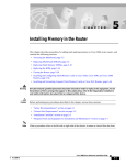
1
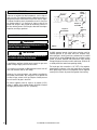
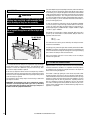
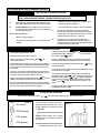
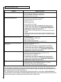
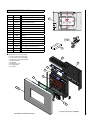
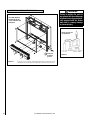
INSTALLATION AND OPERATION MANUAL TM Catalytic Vent-Free Wall-Mounted Gas Fireplace Models: X-FIRES-1000-NG and X-FIRES-1000-LP P/N 506023-01 REV. B, 11/2008 Installer: Leave This Manual With The Appliance. Consumer: Retain This Manual For Future Reference. In the Commonwealth of Massachusetts: • Installation must be performed by a licensed plumber or gas fitter • See Table of Contents for location of additional Commonwealth of Massachusetts requirements Portland US Report No. 317-F-10-5 X-Fires™ 1000 WARNINGS •Hot! Do not touch! This appliance will be hot during operation and will retain heat for a while after shutting off the appliance. Severe burns may result. • Carefully supervise children in the same room as appliance. •Due to high temperatures, the appliance should be located out of traffic and away from furniture or draperies. • Do not place clothing or other materials on or near this appliance. •Improper installation, adjustment, alteration, service or maintenance can cause injury or property damage. Refer to this manual. For assistance or additional information consult a qualified installer, service agency or the gas supplier. •Do not build a wood fire. Do not burn wood or other material in these appliances. •This is an unvented gas log appliance. It uses air (oxygen) from the room in which it is installed. Provisions for adequate combustion and ventilation air must be provided. Refer to Combustion and Ventilation Air Section in this manual. • This appliance may be installed in an aftermarket, permanently located, manufactured (mobile) home, where not prohibited by local codes. • The appliance is only for use with the type of gas indicated on the rating plate. This appliance is not convertible for use with other gases. • Lennox™ vent-free appliances are designed for use as a supplemental heater. They are not intended for continuous use as a primary heat source. WARNING: If the information in this manual is not followed exactly, a fire or explosion may result causing property damage, personal injury or loss of life. Do not store or use gasoline or other flammable vapors or liquids in the vicinity of this or any other appliance. WHAT TO DO IF YOU SMELL GAS • • • • Do not light any appliance. Do not touch any electrical switches; do not use any phone in your building. Immediately call your gas supplier from a neighbor’s phone. Follow your gas supplier's instructions. If your gas supplier cannot be reached, call the fire department. Installation and service must be performed by a qualified installer, service agency or the gas supplier. 1.0 IMPORTANT SAFETY AND WARNING INFORMATION WARNINGS If the information in this manual is not followed exactly, a fire or explosion may result causing property damage, personal injury or loss of life. IMPORTANT Read and understand these instructions completely before installing or operating your unvented room heater. WARNING Failure to keep the primary air opening(s) of the burner(s) clean may result in sooting and property damage. WARNING Failure to comply with the installation and operation instructions provided in this document will result in an improperly installed and operating appliance, voiding its warranty. Any change to this appliance and/or its operating controls is dangerous. Improper installation or use of this appliance can cause serious injury or death from fire, burns, explosion or carbon monoxide poisoning. WARNING Do not allow fans to blow directly into the fireplace. Avoid any drafts that alter burner flame patterns. WARNING Check gas type: The gas supply must be the same as stated on the appliance’s rating plate. If the gas supply is different DO NOT install the appliance. Contact your dealer for the correct model. WARNING Do not use a blower insert, heat exchanger insert or other accessory not approved for use with this heater. WARNING Due to the nature of this product the area around the top of the appliance (i.e. the grill) gets very hot. Care should be taken when operating the appliance. • Children and adults should be alerted to the hazard of high surface temperature and should stay away to avoid burns or clothing ignition. • Young children should be carefully supervised when they are in the same room with the heater. • Do not place clothing or other flammable material on or near the heater. • Any safety screen or guard removed for servicing the heater must be replaced prior to operating the heater. • Installation and repair should be done by a qualified service person. The heater should be inspected before use and at least annually by a professional service person. More frequent cleaning may be required due to excessive lint from carpeting, bedding material, etc. It is important that control compartments, burners and circulating air passageways of the heater be kept clean. • Allow the heater to cool before servicing. Always shut off the gas to the heater while performing service work. • The installation must conform with local codes or, in the absence of local codes with the National Fuel Gas Code, ANSI Z223.1/NFPA 54-latest edition. • The heater and its individual shut-off valve must be disconnected from the gas supply piping system while performing any tests of the gas supply piping system at pressures in excess of 1/2 psig. • The heater must be isolated from the gas supply piping system by closing its individual manual shut-off valve during any pressure testing of the gas supply piping system at test pressures equal to or less than 1/2 psig. • Keep heater area clear and free from combustible materials, gasoline and other flammable vapors and liquids. • Do not use this heater if any part has been under water. Immediately call a qualified service technician to inspect the room heater and to replace any part of the control system and any gas control which has been under water. • Input ratings are shown in BTU per hour and are for elevations up to 4,500 feet. Do not install this heater at an elevation above 4,500 feet if the gas supply has not been derated for that elevation. Consult your local gas supplier. (For operation at elevations above 4,500 feet, equipment ratings shall be reduced at the rate of 4 percent for each 1,000 feet above 4,500 feet before selecting appropriately sized equipment). When installing any vent-free appliance at elevations above 4500 feet, nuisance pilot outages may occur. • Ensure that the heater is clean when operating. Excessive dust accumulation on the burner will increase the amount of carbon monoxide formation and could lead to carbon monoxide poisoning and/or death. • This appliance is intended for supplemental heating. If the appliance is used in a room as the sole source of heat, then condensation may occur on colder surfaces within the room. • Carbon monoxide poisoning – early signs of carbon monoxide poisoning resemble the flu with headaches, dizziness, or nausea. If you have these signs, get fresh air at once! Turn off the gas supply to the appliance and have the heater inspected by a qualified service technician. Some people are more affected by carbon monoxide than others. These include pregnant women, people with heart or lung disease or anemia, those under the influence of alcohol, and those at high altitudes. • Maintain minimum clearances. • Do not install the appliance in a bathroom. • Do not place any objects on top of the appliance. CONGRATULATIONS ON THE PURCHASE OF YOUR NEW GAS APPLIANCE MANUFACTURED BY LENNOX HEARTH PRODUCTS. When you purchased your new gas fireplace, you joined the ranks of thousands of individuals whose answer to their home heating needs reflects their concern for efficiency and our environment. We extend our continued support to help you achieve the maximum benefit and enjoyment available from your new gas fireplace. It is our goal at Lennox Hearth Products to provide you, our valued customer, with an appliance that will ensure years of trouble-free warmth and pleasure. These heaters are fitted with a specially designed pilot utilizing an oxygen depletion sensor (ODS) which responds to the amount of oxygen available in the room and shuts the heater off before the oxygen level drops below 18%. It must not be adjusted or put out of operation. If replaced then manufacturers original parts must be used. The pilot can be relit only when fresh air is available. Refer to the Combustion and Ventilation Air section. The appliance is designed to fit various types of situations as listed in the Installation Requirements. Thank you for selecting a Lennox Hearth Products gas fireplace as the answer to your supplemental home heating needs. This appliance is factory set for operation on the gas type, and at the pressure stated on the appliance rating plate. Sincerely, All of us at Lennox Hearth Products Read all these instructions before commencing installation. All instructions must be left in the possession of the user for safekeeping. TABLE OF CONTENTS Section Contents 1.0 2.0 3.0 4.0 5.0 6.0 7.0 8.0 9.0 10.0 11.0 12.0 13.0 14.0 15.0 16.0 17.0 18.0 19.0 20.0 21.0 22.0 23.0 24.0 25.0 26.0 27.0 28.0 3.0 PACKAGING LIST Page No. Safety And Warning Information . . . . . . . . . . . . . General Information. . . . . . . . . . . . . . . . . . . . . . . Packaging List. . . . . . . . . . . . . . . . . . . . . . . . . . . Appliance Specifications. . . . . . . . . . . . . . . . . . . Unpacking the Appliance. . . . . . . . . . . . . . . . . . . Burn-in Period. . . . . . . . . . . . . . . . . . . . . . . . . . . Codes, Massachusetts & New York. . . . . . . . . . . Combustion And Ventilation Air. . . . . . . . . . . . . . Site Requirements . . . . . . . . . . . . . . . . . . . . . . . . Gas Supply Routes . . . . . . . . . . . . . . . . . . . . . . . Preparing The Appliance. . . . . . . . . . . . . . . . . . . Mounting The Appliance. . . . . . . . . . . . . . . . . . . Fitting the Surround Assembly . . . . . . . . . . . . . . Checking The Burner . . . . . . . . . . . . . . . . . . . . . . Connecting A Gas Line . . . . . . . . . . . . . . . . . . . . Checking The Gas Connections . . . . . . . . . . . . . . Gas Pressure Check. . . . . . . . . . . . . . . . . . . . . . . Spark Gap. . . . . . . . . . . . . . . . . . . . . . . . . . . . . . Briefing The Customer. . . . . . . . . . . . . . . . . . . . . Servicing. . . . . . . . . . . . . . . . . . . . . . . . . . . . . . . Catalysts. . . . . . . . . . . . . . . . . . . . . . . . . . . . . . . Testing For Firebox Leakage . . . . . . . . . . . . . . . . Lighting Instructions & Turning Off Appliance. . . Troubleshooting Guide. . . . . . . . . . . . . . . . . . . . . Replacement Parts List. . . . . . . . . . . . . . . . . . . . Positioning Of Field Assembled Parts. . . . . . . . . Specifications . . . . . . . . . . . . . . . . . . . . . . . . . . . Product Reference Information . . . . . . . . . . . . . . 2 3 3 3 4 4 4 5 6 6 7 8 9 10 10 11 11 12 12 13 14 14 15 16 17 18 19 20 2.0 GENERAL INFORMATION This appliance is a high efficiency, unvented, flame effect gas heater. It provides radiant and convected warmth both efficiently and safely utilizing the latest type catalytic convertor burner technology. The appliance does not require a flue system of any type as the catalytic converter cleans the flue products to provide a complete combustion system, which is intrinsically safe. Quantity Description Fireplace 1 1 1 1 1 Firebox, burner assembly and wall mounting plate Installation and Operation Manual Warranty Certificate Screw and wall plug pack Rubber grommet Surround Assembly (required - sold separately. see Page 19 for ordering information) 1 1 Surround Assembly Installation Instruction Sheet 4.0 APPLIANCE SPECIFICATIONS X-Fires 1000 Gas Type Natural Gas Propane Gas (LP) 10.5” w.c. 6” w.c. 13” w.c. 11” w.c. 5” w.c. 10” w.c. Max Energy Input 8,870 BTU/hour 7,500 BTU/hour Min Energy Input 5,110 BTU/hour 5,110 BTU/hour Pilot Energy Input 560 BTU/hour 560 BTU/hour Burner Pressure (manifold) 3.5” w.c. 1.1” w.c. 5.6” w.c. 2.9” w.c. 1.45mm (0.057”) 1.03mm (0.04”) SIT/Bray 9082 SIT/Bray 9284 Gas inlet pressure Max. Min. Regulator Pressure Setting High Low Main burner flow restrictor (burner orifice) Oxypilot Gas Inlet Connection 3/8” NPT at regulator 3/8” NPT at regulator Ignition Piezo spark Piezo spark Spark Gap 1/8” - 3/16” 1/8” - 3/16” Please see Data Plate affixed to appliance for current data. This appliance is for use only with the gas type, and at the pressure stated on the appliance Data Plate. Table 1 5.0 UNPACKING THE APPLIANCE Remove the straps and the top lid of the outer packaging, remove any instructions or fixing kits. Read ALL these instructions before continuing to unpack or install this appliance. Lift off the remaining packaging components. Check that the components supplied with the packaging list on Page 3. Please dispose of all the packaging materials at your local recycling center. 6.0 BURN-IN PERIOD On initial light up of a new appliance, the ‘newness’ will burn off within the first few hours of operation. During this period some smoke may be emitted from outlet grill, this should be no cause for concern. Accordingly, the room should be well ventilated with all windows and doors open during this period. Depending on your use, the burn-in period may take a few hours or a few days. Also if you have a sensitive sense of smell you may notice slight odors during operating after the burn-in period is over. KEEP YOUR HOUSE WELL VENTILATED DURING THE BURN-IN PERIOD. THE ODOR AND HAZE EMITTED DURING THE BURN-IN PERIOD CAN BE QUITE NOTICEABLE AND MAY SET OFF A SMOKE DETECTOR. MAKE SURE SMOKE DETECTORS ARE NOT TOO CLOSE TO THE FIREBOX (CHECK WITH YOUR LOCAL CODE FOR ALLOWABLE DISTANCES). 7.0 CODES Adhere to all local codes or in their absence the latest edition of The National Fuel Gas Code ANSI Z223.1 / NFPA 54 - latest edition which can be obtained from The American National Standards Institute, Inc. (1430 Broadway, New York, NY, 10018) or National Fire Protection Association, Inc. (Batterymarch Park, Quincy, MA, 02269). Seller of unvented propane or natural gas fired supplemental room heaters in the Commonwealth of Massachusetts shall provide to each purchaser a copy of 527 CMR 30 upon sale of the unit. This Lennox Hearth Products Unvented Gas Room Heater is certified by OMNI-Test Laboratories, Inc to ANSI Z21.11.2 standard. Massachusetts Requirements These fireplaces are approved for installation in the US state of Massachusetts if the following additional requirements are met: • Unvented Room Heaters shall be installed in accordance with 527 CMR 30.00 and 248 CMR 3.00 through 7.00: • Installation and repair must be done by a plumber or gas fitter licensed in the Commonwealth of Massachusetts • The flexible gas line connector used shall not exceed 36 inches (92 centimeters) in length. • The individual manual shut-off must be a T-handle type valve. • Vent-Free appliances may NOT be installed in bedrooms or bathrooms. • A working smoke detector must be installed in the area where ventfree appliances are installed. Seller of unvented propane or natural gas-fired supplemental room heaters shall provide to each purchaser a copy of 527 CMR 30 upon sale of the unit. New York: These fireplaces are approved for installation in the US state of New York, but not in New York City. 8.0 COMBUSTION AND VENTILATION AIR This heater shall not be installed in a confined space or unusually tight construction unless provisions are provided for adequate combustion and ventilation air. The heater may be located in unusually tight construction provided the space is unconfined, or if confined, is provided with two permanent openings communicating directly with an additional room(s) of sufficient volume so that the combined volume of all connected spaces meets the criteria for an unconfined space, (National Fuel Gas Code NFPA 54 / ANSI Z223.1 - latest edition, Section on Air for Combustion and Ventilation. Generally 50 ft3 per 1,000 BTU input of all operating appliances in the space. The National Fuel Gas Code, ANSI Z223.1/NFPA 54, defines a confined space as a space whose volume is less than 50 ft3 per 1,000 BTU/Hr (4.8 m3 per kW) of the aggregate input rating of all appliances installed in that space and an unconfined space as a space whose volume is not less than 50 ft3 per 1,000 BTU/Hr (4.8 m3 per kW) of the aggregate input rating of all appliances installed in that space. Rooms communicating directly with the space in which the appliances are installed, through openings not furnished with doors, are considered a part of the unconfined space. Unusually tight construction is defined as construction where: a. Wall and ceilings exposed to the outside atmosphere have a continuous water vapor retarder with a rating of one perm (6 X 10-11 kg per pa-sec-m2) or less with openings gasketed or sealed; b. Weather stripping has been added on operable windows and doors; and c. Caulking or sealants are applied to areas such as joints around window and door frames, between sole plates and floors, between wall ceiling joints, between wall panels, at penetrations for plumbing, electrical, and gas lines, and at other openings. Example: Vent-free heater #1 Vent-free heater #2 Gas appliance #1 (water heater) Total = 9,000 BTU/Hr 23,000 BTU/Hr 35,000 BTU/Hr 67,000 BTU/Hr * Do not include direct-vent gas appliances. Direct-vent is sealed combustion and draws combustion air from the outdoors. 4. Compare the maximum BTU/Hr the space can support with the actual amount of BTU/Hr used. _______ BTU/Hr (max. the space can support) _______ BTU/Hr (actual amount of BTU/Hr used) Example: 61,440 BTU/Hr (max. the space can support) 67,000 BTU/Hr (actual amount of BTU/Hr used) The space in the previous example is a confined space because the actual BTU/Hr used is more than the maximum BTU/Hr the space can support. You must provide additional fresh air. Your options are: a.Rework equations adding the space of adjoining room(s). If the extra volume provides an unconfined space, then remove door or add ventilation grills between rooms. Refer to National Fuel Gas Code, ANSI Z223.1/NFPA 54-latest edition, Section "Air for Combustion and Ventilation". b. Vent room directly to the outdoors. Refer to National Fuel Gas Code, ANSI Z223.1/NFPA 54-latest edition, Section "Air for Combustion and Ventilation". c. Install a lower BTU/Hr heater to make the area an unconfined space. If the actual BTU/Hr used is less than the maximum BTU/Hr the space can support, then the space is an unconfined space. You will need no additional fresh air ventilation for an unconfined space. Use the following equations to determine if you have a confined or unconfined space. 1.Determine the volume of space — ft3. Length x Width x Height = _____ ft3 (Include adjoining rooms with doorless passageways or ventilation grills between rooms). Example: 24' (L) x 16' (W) x 8' (H) = 3072 ft3 2.Divide the volume of space by 50 ft3 to determine the maximum BTU/Hr the space can support. WARNING If the area in which the heater may be operated is smaller than that defined as an unconfined space or if the building is of unusually tight construction, provide adequate combustion and ventilation air by one of the methods described in the national fuel gas code, ANSI Z223.1/NFPA 54, Air for Combustion and Ventilation Or applicable local codes. ______ (volume of space – ft3)/ 50 ft3 = (Maximum BTU/Hr the space can support) Example: 3072 ft3 / 50 ft3 = 61.44 or 61,440 BTU/Hr the space can support. 3.Add the BTU/Hr of all the fuel burning appliances in the space. Vent-Free heater Gas appliance #1* Gas appliance #2 + Gas appliance #3 + Total = _______ BTU/Hr _______ BTU/Hr _______ BTU/Hr _______ BTU/Hr _______ BTU/Hr 9.0 SITE REQUIREMENTS This appliance is designed to be wall-hung. Do not recess any part of the appliance into the wall. This appliance may be installed in any room in a home except bathrooms - or areas where large amounts of steam are likely to be generated. This appliance is approved for installation into a bedroom . It should be noted that heaters create warm air currents. These currents move heat to wall surfaces next to the heater. Installing the heater next to vinyl or cloth wall coverings or operating the heater where impurities in the air (such as tobacco smoke or candle smoke) exist, may discolor walls. Installation in living rooms is common, however other rooms such as kitchens, dining rooms and hallways are permitted, providing a suitable gas supply is available, and rooms sizing and ventilation requirements are strictly adhered to (see Section 8.0). The appliance is designed to be versatile, and as such will operate correctly when exposed to normal gentle drafts experienced within the home. It is not recommended, however that the appliance be installed in areas where it is likely to be exposed to persistent strong drafts, that may be generated by outside doors or windows, air vents etc. It is recommended that the appliance should not be installed within 20" of any air vent. CAUTION The back of the appliance may be installed directly onto a combustible wall or non-combustible wall, providing the area behind the appliance is flat and does not interfere with the various vent holes in the back panel of the appliance. CLEARANCES TO NON-COMBUSTIBLES Non-combustible surfaces are defined as brick, metal, marble, concrete etc. and also a number of man-made materials impervious to flame. If in doubt refer to the material manufacturer for further information before proceeding with installation. Clearance to the sides of the appliance are 4” but curtains, drapes and other fabrics are not permitted within a distance of 20” of the appliance sides. No such materials are permitted directly above the appliance regardless of distance. The minimum clearance to the ceiling above the appliance is 32” measured from the top of the appliance glass panel. Combustible materials should not be positioned directly in front of the appliance within a distance of 40”. Under no circumstances should any electrical equipment e.g. plasma screen TV sets etc. be positioned on the wall above the appliance. The appliance is designed to be wall mounted alone and not in conjunction with any type of combustible fire surround. No combustible shelves should be positioned on the wall above the appliance. It should be established that any mirrors or picture frames etc. to be positioned on the wall above the appliance are able to withstand prolonged exposure to moderate heat and moisture before proceeding with their installation. The wall must be structurally sound and constructed from a material capable of withstanding moderate heat. Finished plaster, conventional wall paper and dry-lined plasterboard are examples of suitable materials. Materials such as flock, blown vinyl and embossed paper which are sensitive to even small amounts of heat should be avoided as scorching and or discoloration may occur over time. If the appliance is to be mounted on a dry-lined wall or a timber framed construction wall then the integrity and ability of the wall to carry the weight of the appliance must be confirmed. It is important in these circumstances that any vapor control barrier is not damaged, and that any structural members of the house frame are not damaged. The appliance may be positioned as close to a solid floor (i.e. stone, wooden laminate etc.) as the particular design of fire frame permits, however it is not permitted to install the appliance within 4” of carpet, rugs or fabric materials of any kind. This dimension is measured vertically to the bottom of the appliance frame. 10.0 GAS SUPPLY ROUTES Gas connection: The heater gas inlet connection is 3/8” NPT at the regulator, located below the burner, in the right hand side of the heater. There are four possible entry points for the gas supply pipe-work to enter the appliance firebox. These entry points are ‘knock out’ type holes (shown in Figure 1). Clearances to the sides of the appliance are 4”. Clearance to the front of the appliance is 20”. The appliance may be installed with or without a non-combustible hearth. If a hearth is fitted, the size and design may be as desired. A non-combustible shelf of any depth may be positioned above the appliance provided it is no closer than 16” from the top of the appliance glass panel and the wall above the appliance is non-combustible. CLEARANCES TO COMBUSTIBLE MATERIALS Combustible materials are defined as wood, fabrics, or other materials likely to combust if exposed to flame. Generally, any material, which is likely to discolor, melt or misshape when exposed to moderate heat, should be considered as a combustible material or surface. Figure 1 - Gas Supply Entry Points Non-concealed gas connections may be made using the entry points at either end of the firebox or the one in the bottom of the firebox. A concealed gas connection may be made using the knock out hole in the center back of the firebox. Select the most appropriate entry point and knock out the relevant hole in both the firebox and the outer casing. No more than 59" of 1/4" diameter pipe must be used to avoid unnecessary pressure drops. If a concealed gas connection is to be made, the supply pipe should always be sleeved through walls and floors using the shortest possible route. 1. Remove the Grill. Note: This design of grill not fitted to widescreen model Note : X-Fire 1000 shown as example 5. Widescreen models : Remove two self-tapping screws from the Left hand side of the outer casing and one from the right hand side. For concealed supply pipe routing, pipes must (where possible) be vertical and providing there is sufficient wall thickness available, they should be placed in pipe chases. Horizontal pipe runs should be avoided where possible. Prior to chasing a solid wall, an inspection should be made to note the proximity of any cables/ sockets outlets which may already be buried. Pipes must be secured using suitable clips and protected against corrosion. Ideally factory finished protected pipe-work and fittings should be used. Joints should be kept to a minimum and compression fittings must not be used. The pipe-work installation must be tested for soundness before any protection is applied and/or the pipe-work and fittings are buried. 11.0 PREPARING THE APPLIANCE IMPORTANT NOTE: All gas piping must be done by a licensed plumber or gas fitter and must conform to the requirements of the National Fuel Gas Code NFPA 54 / ANSI Z223.1 - latest edition. 3. Remove spindle retaining pin 2. Remove retaining wing nuts 1. Remove the two retaining screws on each side of the upper grill and remove the grill from the outer casing. 2. Remove the two retaining wing nuts from the retaining studs that protrude into the lower part of the main firebox as shown. The control knob is located on the lower right hand side of the outer casing, and is mounted in an indicator bracket, which has a metallic indication ‘pip’ (indication mark for proper knob alignment). Both the knob and the indicator bracket should be removed as follows; 4. Remove control indicator bracket and control knob Figure 2 3. Remove the retaining pin from the gas valve spindle and withdraw the control knob and the spindle extension from the right hand side of the appliance. 4. Remove the four retaining screws and the indicator bracket. The firebox may now be detached from the outer casing. NOTE: DIAGRAMS & ILLUSTRATIONS ARE NOT TO SCALE A full size fitting template is supplied to assist with wall mounting. (see Figure 3). 12.0 MOUNTING THE APPLIANCE After having selected the final mounting position of the appliance, taking into account the site requirements as specified in these instructions, the integrity of the wall, and the feasibility of the proposed supply pipe routing, the firebox of appliance may be secured to the wall. If the heater is to be installed on a studded wall with conventional 16” stud spacing then a wall mounting plate is supplied to enable this. NOTE: THIS APPLIANCE MUST BE SECURED DIRECTLY TO THE STUDS AT THE FIXING POINTS THAT ARE 16" DISTANCE (see template below). First locate the studs and using suitable fixings, screw the mounting plate to the wall via the four mounting holes. The heater may then be hung onto the mounting plate. The bottom of the heater may be secured onto the lower mounting studs using the wing-nuts or the hex nuts provided. WARNING The wall where the appliance is to be installed must be capable of long-term support of the total load of the appliance. Measures should also be taken to ensure sufficient strength to withstand the force of earthquakes, vibration and other external forces. Mark the positions shown as “Fixing Points” on the wall. If the appliance is to be mounted on the inner leaf of a conventional cavity wall, or a solid wall, drill four holes using a 5/16" masonry bit, to a depth of 1-11/16". Insert the fiber wall plugs provided. To ensure customer safety, be sure to design the installation so that the strength of both the wall and any wall fixings used are sufficient. Lennox Hearth Products assumes no responsibility for injuries and damages that may occur due to improper installation or handling. If the appliance is to be mounted on a dry lined wall or a timber framed construction wall then special cavity screw fixings will be required which are not supplied with this product. These should be constructed from metal and not plastic. The appliance should not be installed until all dry wall sanding and wall painting has been completed. If a concealed gas connection is to be made ensure the gas supply pipe is in it’s final position and can enter the appliance in the correct position when the appliance is hung on the wall. Incorrect installation can cause the appliance to fall from the wall and cause injury. Do not block the ventilation holes of the appliance. The wall onto which the appliance is installed must be flat. Install only on a vertical surface. Avoid sloped surfaces. Installation onto anything other than a vertical wall may result in fire, damage or injury. POSITION SPIRIT LEVEL ALONG THIS EDGE TO LEVEL TEMPLATE BEFORE MARKING OUT WALL COLOQUE EL NIVEL SOBRE ESTE BORDE PARA NIVELAR LA PLANTILLA ANTES DE MARCAR LA PARED FIXING POINTS PIERCE TEMPLATE TO MARK HOLE POSITION ON WALL X 4 PUNTOS DE SUJECION PERFORE LA PLANTILLA PARA MARCAR LA POSICION DE LOS 4 TALADROS EN LA PARED Clearance to combustible sidewalls 4” (both sides) ADVERTENCIA ESPACIO LIBRE HASTA MATERIALES COMBUSTIBLES Deben mantenerse en todo momento los siguientes espacios libres. El no hacerlo puede causar un riesgo de incendio. Consulte el manual de instrucciones suministrado con este aparato para obtener información completa. El espacio de 32” hasta un techo combustible se mide desde el borde superior del panel de vidrio del aparato Espacio libre delante del calentador 20” 31/8” (78.6mm) IMPORTANT : Fabrics, curtains and drapes are not permited above the heater at any distance and within 20” of the heater sides. No combustible shelves of any size are permitted above the heater. F860041/A CONCEALED GAS INLET ENTRADA DE GAS OCULTA Espacio hasta paredeslaterales combustibles 4” (ambos lados) Nota: No se requiere espacio libre desde el borde inferior del marco del calentador en caso de pisos combustibles duros. Se requiere un espacio mínimo de 4” entre el calentador y cualquier alfombra, moqueta o revestimiento de suelo de tela. CONSULTE EL MANUAL DE INSTRUCCIONES. IMPORTANTE: No se permite la colocación de telas, cortinas y similares por encima del calentador a cualquier distancia, ni a una distancia de 20” de los laterales del calentador. No se permiten estantes combustibles de cualquier tamaño por encima del calentador. F860041/A X-FIRES™ 1000 F860487 - ISSUE A - PRW Figure 3 - Wall Fixing TemplateFocalPointFires Single 27/06/08 F860487 Lennox 1000 fitting template Artwork Size: W1002 x H642 NOTE: DIAGRAMS & ILLUSTRATIONS ARE NOT TO SCALE CONTORNO DE LA APARATO APPLIANCE OUTLINE Clearance in front of heater 20” Note : Zero clearance from bottom of heater frame required for hard combustible floors. Minimum 4” clearance required to rugs or any fabric floor coverings. REFER TO INSTRUCTION MANUAL IMPORTANTE ESTE APARATO UNICAMENTE DEBE SER COLGADO EN UNA PARED. NO EMPOTRE NINGUN ELEMENTO DE ESTE APARATO. ESTA PLANTILLA SIRVE UNICAMENTE PARA MARCAR LOS PUNTOS DE FIJACION. RETIRE LA PLANTILLA ANTES DE COLOCAR LE APARATO. FIREBOX OUTLINE CONTORNO DE LA CAMARA DE COMBUSTION Clearance to combustible ceiling 32” measured from top of appliance glass panel IMPORTANT THIS APPLIANCE IS TO BE WALL HUNG ONLY. DO NOT RECESS OR INSET ANY PART OF THE APPLIANCE. THIS TEMPLATE IS FOR THE MARKING OF FIXING POINTS ONLY. DO NOT INSTALL THE APPLIANCE WITH THIS TEMPLATE IN PLACE. CENTRE LINE LINEA DE CENTRO WARNING CLEARANCES FROM COMBUSTIBLE MATERIALS The following clearances must be maintained at all times. Failure to do so may result in the risk of a fire. For full information refer to the instruction manual provided with the heater. WALL MOUNTED VENT FREE FITTING TEMPLATE PLANTILLA PARA LA INSTALACION DE CHIMENEAS DE PARED SIN SALIDA DE HUMOS 6 3/8” (160mm) 8 13/16” (225mm) 16” (406mm) It is recommended that the burner height, where possible, should be approximately 4 ft. from the floor. This will give the best viewing position. When selecting the height, ensure that the clearance to the ceiling is 32" minimum, as specified on Page 6. After selecting the final mounting position of the appliance, taking into account the site requirements as specified in Section 9.0 of these instructions, the integrity of the wall, and the feasibility of the proposed supply pipe routing, the firebox of the appliance may be secured to the wall. Due to the weight of the front surround assembly, it is possible to fasten the outer casing to the wall in up to nine positions, depending on the strength/condition of the wall. If in doubt always use extra fixings! Use a bubble level to ensure that the outer casing is level at all times during installation. 13.0 FITTING THE SURROUND ASSEMBLY Due to the weight of the frame assembly, it is recommended to seek assistance for this operation. The frame assembly will be supported by keyhole slots by four M6 screws which protrude from the front of the outer casing (see Figure 5) . Ensure each screw is unscrewed approximately one turn from the fully screwed in position in order to create a 1/16" gap (shown). Hang the surround assembly onto the outer casing, starting with the two bottom fixings, ensuring that the corresponding keyhole shaped holes engage the screw heads fully. Insert the screws into two of the upper holes, leaving 3/16" protruding from the wall. Temporarily hang the outer casing on the wall, and mark any additional fixing points as required. If the appliance is to be fitted to a lightly colored wall, it is advantageous to paint this wall area with black or dark paint in the vicinity of the lower rectangular slots on the outer casing. This will mask the wall when viewed from the front of the appliance. Ensure paint is fully dry before mounting the appliance. Use the outer casing as a template to mark this area on the wall. Remove the outer casing from the wall and drill holes for the additional fixing points as required. Insert either wall plugs or cavity screw fixings as required. Re-position the outer casing on the wall and using a bubble level to check the casing is square and level, tighten all of the fixing screws fully. Heat Shield Now, with the outer casing fixed to the wall, the main firebox can be secured in position. The firebox is held on the outer casing using four studs and two normal nuts (upper fixings) and two wing nuts (lower fixings). Make sure that the upper nuts are unscrewed approximately one turn from the fully tightened position in order to create a 1/16" gap as shown in Figure 4. The firebox may now be hung onto the top studs, and then pushed onto the lower studs so that the lower studs protrude through the lower fixing holes in the back panel of the firebox. IMPORTANT NOTE: Ensure that the surround is positioned with the heat shield on top as shown. Next, re-fit the grill, the indicator bracket and the control knob and spindle, and secure in position using the correct fixing screws (re-fitting is the opposite of removal as detailed in these instructions). Figure 5 1/16" Figure 4 NOTE: DIAGRAMS & ILLUSTRATIONS ARE NOT TO SCALE 14.0 CHECKING THE BURNER Regulator There are no imitation fuel bed components, such as logs or rocks, to install. The appliance features a ribbon burner which is designed to produce a continuous band of flame over its length. The burner should be visually inspected to ensure it is free from any foreign matter. If it is necessary to clean or dust off the burner then the glass door should be removed by removal of the four retaining screws. Re-fit the glass door after cleaning or inspection, ensuring a good seal. Manual Shut-Off Valve Union Fireplace or Firebox Wall Wall Shut-Off Key Fireplace or Firebox Wall 15.0 CONNECTING A GAS LINE 3" WARNING Connecting directly to a unregulated propane (L.P.G.) tank may cause an explosion. IMPORTANT Hold heater regulator with a wrench to prevent movement when connecting to inlet piping. A qualified gas appliance installer must connect the gas room heater to the gas supply. Consult all local codes. The installer must provide an ANSI approved manual shut off valve, flex connector and 3/8" NPT fitting. Route gas line using techniques and materials prescribed by local and/or national codes. Only use pipe of 1/2" or greater size to allow full gas volume to the gas fireplace. Undue pressure loss will occur if the pipe is too small. Down Figure 6 An ANSI approved manual shut-off valve and union must be installed upstream of the heater within the fireplace cavity when rigid pipe is used. Ensure that a sediment trap is installed upstream of the heater (Figure 4) within the structure’s piping system to prevent moisture and contaminants from passing through the pipe to the heater controls and burner. Failure to do so could prevent the heater from operating reliably. The heater gas inlet connection is 3/8” NPT at the regulator, located below the burner, in the right hand side of the heater. When tightening up the joint to the regulator hold the regulator securely with a wrench to prevent the regulator from moving. An external regulator must be used on all propane (L.P.G.) heaters, in addition to the regulator fitted to the heater, to reduce the supply tank pressure to 13" w.c. (maximum). 10 Sediment Trap NOTE: DIAGRAMS & ILLUSTRATIONS ARE NOT TO SCALE 16.0 CHECKING THE GAS CONNECTIONS WARNING Never use an open flame to check for leaks. Turn on gas supply and test for gas leaks using a gas leak test solution (also referred to as bubble leak solution). NOTE: using a soapy water solution (50% dish soap, 50% water) is an effective leak test solution, but it is not recommended, because the soap residue that is left on the pipes/fittings can result in corrosion over time. A.Light the appliance (refer to the lighting instructions label in the control compartment or on Page 14). B.Brush all joints and connections with the gas leak test solution to check for leaks. If bubbles are formed, or gas odor is detected, turn the gas control knob (off/pilot/on) to the “OFF” position. Either tighten or refasten the leaking connection, then retest as described above. If the pressure is too high, the gas supply meter may be set incorrectly. This should be checked with the appliance running and if necessary reset by the gas supplier. If the burner pressure is too low, then check the inlet pressure with the appliance running. If this is less than the inlet pressure stated in Table 1, it will need to be reset by the gas supplier. If the setting pressure is too low, but the meter pressure is acceptable, then a problem in the supply pipework is to be suspected. This may be dirt and debris, kinked or inadequate size pipes, restriction in a fitting, shut off elbow not fully open or solder flashing across a joint. Identify the cause of the restriction and rectify. Switch the fireplace off, disconnect the U gauge and refit the test nipple screw. Light the fireplace and check test nipple for gas tightness. In the event that the burner pressure is not in accordance with the figures stated in the Table 1 of these instructions, the appliance must not be commissioned, and the dealer should be contacted for guidance. The pressure regulator on manual models is preset and locked to avoid tampering. If the pressure is not as specified in Table 1 on Page 3, replace the burner assembly (see Page 17 for ordering information). Replace the test point screws after pressure measurement ensuring no gas leaks. All instructions must be left in the possession of the user for safekeeping. C.When the gas lines are tested and leak free, be sure to rinse off the leak testing solution. D.Observe the individual tongues of flame on the burner. Make sure all ports are open and producing flame evenly across the burner. If any ports are blocked, or partially blocked, clean out the ports. 17.0 GAS PRESSURE CHECK Checking Manifold Pressure at Provided Test Point (see Figure 7a) The pressure test point is located on the left hand side of the appliance, on the main burner pipe, next to the brass restrictor adjacent to the front left hand side burner bracket. Release the setting pressure test point screw, and attach a U gauge. Light the fire on the HIGH setting. Checking Manifold and Inlet Pressure at Valve (see Figure 7b) - The heater regulator controls the burner pressure which can be checked at the pressure test points located on the control valve itself for burner (manifold) and regulator (inlet) setting pressures. Pressure Test Point (on left side of fireplace) Figure 7a Burner (Manifold) Pressure Regulator (Inlet) Pressure Setting The valve is located on the lower right side of the appliance (see exploded view drawing on Page 17). Release the test point screws and ensure operating pressures are as specified in Table 1 on Page 3 of these instructions. The pressure should be checked with the gas heater burning and the control set to high flame. Figure 7b - Manifold and Inlet Pressure Taps NOTE: DIAGRAMS & ILLUSTRATIONS ARE NOT TO SCALE 11 19.0 BRIEFING THE CUSTOMER 18.0 SPARK GAP The gap between the spark electrode and the pilot should be 1/8” to 3/16” to produce a good spark. There should be no need to adjust this (DO NOT ATTEMPT TO ADJUST THE GAP). If under any circumstances the piezo electric spark fails, the pilot cannot be lit manually. Adjustment to the pilot is Not allowed 1/8" to 3/16" Spark Gap WARNING Do not add logs or ornaments such as pine cones, vermiculite or rock wool. Using these added items can cause sooting. All instructions must be left in the possession of the user for safekeeping. Show the customer how to light and control the fire. If at all possible, show the customer how to remove and replace the surround assembly and glass door assembly. After commissioning the appliance, the customer should be instructed on the safe use of the appliance and the need for regular servicing. Frequency of service depends on usage, but MUST be carried out at least once annually. Advise that cleaning of the appliance may be achieved when the appliance is cold using a damp cloth and mild detergent on most surfaces. Figure 8 - Proper Spark Gap Advise that the fireplace will emit a "newness" smell for a time after initial commissioning and that extra ventilation may be needed during this time. Advise to user to never place any objects on top of the appliance or obstruction this area in any way. A periodic visual check of the pilot flame and the burner flame should be carried out. 12 20.0 SERVICING WARNING Turn off the appliance and allow to cool before cleaning. Verify proper operation after servicing. WARNING Any change to this heater or its controls can be dangerous. WARNING You must keep control areas, burners and circulating air passageways of appliance clean. Failure to keep the primary air opening(s) of the burner clear may result in sooting and property damage. Inspect these areas of appliance before each use. Have appliance inspected yearly by a qualified service person. Appliance may need more frequent cleaning due to excessive lint form carpeting, bedding material, etc. WARNING No adjustments are to be made to the ODS pilot system. Tampering with this system can be extremely hazardous. The appliance should be checked on an annual basis to ensure it is working safely and that there is no excessive build up of soot. The frequency of service will depend on usage, but MUST be carried out at least once annually. Servicing must be carried out by a qualified person, such as a NFI certified technician. Turn off the fireplace at the gas supply. Ensure that the fireplace is fully cold before attempting service. A suggested procedure for servicing is detailed as follows; 1. Lay out the dustsheet and tools. 2. Remove the granite or limestone surround assembly as described in Section 13.0, only in reverse. 3. Remove the glass door assembly (4 screws) and clean carefully. Remove the valve cover plate (4 screws). 4. Inspect the burner and the catalysts (see Section 21.0) and clean if necessary with a soft brush. Ensure there are no defects or obstructions that may prevent the satisfactory flow of combustion products through the catalysts. 5. Disconnect the gas supply. IMPORTANT NOTE: This must be done by a licensed plumber or gas fitter and must conform to the requirements of the National Fuel Gas Code NFPA 54 / ANSI Z223.1 - latest edition. 6. Undo the four screws retaining the burner support brackets. 7. Remove the burner unit, strip off the burner pipes and clean thoroughly. 8. Clean the in-line restrictor, pilot assembly and the burner tube. Clean the exterior of the pilot assembly with a soft brush and blow through the flame ports on the pilot head. Check the aeration holes are free from lint or dirt. Do not attempt to remove the pilot injector as this can cause damage. The pilot assembly is a non-serviceable item and should not be taken apart. Aeration holes must be clear internally for proper operation. NEVER MODIFY OR BEND THE THERMOCOUPLE TO MAKE THE PILOT STAY LIT. Modifications are dangerous and can have serious unseen effects on safety. If the pilot will not stay lit there is a problem with dirt, the gas supply to it, or the thermocouple needs replacement. 9. Re-assemble components. 10.Re-connect the gas supply. Turn on the gas supply and perform a gas leak test using gas leak test solution. Check pilot and burner for good ignition. 11.Refit the valve cover and retaining screws. 12.Refit the glass door assembly (see Section 26.0). 13.Refit the surround assembly as described in Section 13.0. 14.Check the purpose provided ventilation is unobstructed. 15.Light the fireplace and test setting pressures. 16.Check safe operation of the appliance. NOTES: • The gas valve is a non-serviceable item. If this needs replacement, remove the cover plate then the securing screw holding the valve bracket in place, remove all pipe unions, and the complete valve. Replacement must be original manufacturers parts. • Ensure setting pressures are as stated in Table 1 on Page 3. GLASS PANEL -This can be cleaned with a suitable glass cleaner. The following solutions are approved for use to clean glass. • Non-ammonia based household cleaner • 50% -50% mix of white vinegar and water • Gas fireplace/stove glass cleaner PAINTED AREAS - These can be cleaned using a dry cloth. LIMESTONE SURFACES: Remember that limestone is porous and therefore susceptible to marking in use. The limestone frame may be cleaned with a small amount of warm soapy water. Any stubborn stains may be removed with a diluted liquid household bleach and water solution. Superficial scratches or stubborn surface stains can be smoothed out using a fine grade wet and dry sandpaper. Joints may be grouted using a matching tile grout. The limestone frame may be sealed with an appropriate stone sealer (consult the retailer). This will give some protection against staining such as red wine, tea or coffee, but may darken the stone slightly. GRANITE SURFACES: In everyday use, a soft lint-free duster should be used to keep the granite clean. Other marks, such as fingerprints may be removed from the granite frame by using household window-glass cleaner. For specific servicing instructions, see relevant sections. 13 21.0 CATALYSTS WARNING Do not block the catalysts or the appliance outlet grill. Blockage may cause high carbon monoxide levels and/or breakage of the glass door assembly. WARNING Do not operate the appliance with the catalyst units removed. DO NOT BLOCK THESE AREAS Turn on the fireplace as per the operating instructions, and run at maximum setting for 15 minutes. Position gas sample probe directly over a catalyst via the outlet grill, on top of the appliance. Record the carbon dioxide (CO2) concentration and then the carbon monoxide (CO) concentration as displayed by the analyzer - also noting the units in which the values are expressed. Most analyzers display carbon dioxide (CO2) concentrations in percentage (%) terms and carbon monoxide concentration in parts per million (ppm) terms. In order to calculate the combustion ratio for the appliance (CO/CO2) it is first necessary to express both gas concentrations in terms of per centage. To convert from parts per million (ppm) to a percentage (%) divide the ppm figure by 10,000. Examples : 35ppm = 0.0035%, 15ppm = 0.0015%, 5ppm = 0.0005%. Now divide the concentration of carbon monoxide (CO) expressed in percent by the concentration of carbon dioxide (CO2) to obtain the appliance combustion ratio. CO (%) CO2 (%) = ratio The combustion ratio of the gasses emitted by the catalytic convertor should not exceed 0.0015. If replacing, firstly, remove the glass door assembly as described in Section 26.0. The catalysts are located on the top of the internal firebox and can be removed be unscrewing the retaining nuts securing the clamping plate. Remove the catalysts and seals and discard. Refit a new catalysts and seals in reverse order, ensure the catalysts and door have good seals. Figure 9 - Catalysts and Outlet Grill 22.0 TESTING FOR FIREBOX LEAKAGE It is recommended that the catalysts are inspected for signs of damage and dirt during routine servicing procedures. The expected life of the catalysts is in excess of 11,000 hours (10 years of normal use). After this time the catalyst should be replaced. If there are any deposits of dirt or soot on the catalysts they should be cleaned with a soft brush and a vacuum cleaner. If removed for cleaning ensure the seals are in good condition before replacing the catalyst. New seals will usually be required. The performance of the catalyst may be checked using a combustion gas analyzer as follows. IMPORTANT: The temperature of the gases emitted by the catalytic converters reach very high temperatures (up to 700° F). Measuring gas of this temperature may damage some types of gas analyzers. If in doubt consult the equipment manufacturer. 14 Appliances that are several years old or have been extensively dismantled should be checked for soundness. It is important that all the products of combustion pass through the catalytic converters at the top of the firebox before leaving the appliance. The firebox is heated by lighting for a few minutes to provide a flow through the firebox. The burner is then shut off and a smoke pellet or match introduced at the base of the fire underneath the burner tray. Large quantities of smoke will emerge from the top of the appliance, but none should emerge from the joints or gasket faces, especially around the door. It is important to note that the appliance can never be expected to be 100% smoke tight and small quantities of smoke may be seen in corners of joints and gasket faces etc without affecting safety when the appliance is in operation. NOTE: DIAGRAMS & ILLUSTRATIONS ARE NOT TO SCALE 23.0 LIGHTING INSTRUCTIONS & TURNING OFF APPLIANCE FOR YOUR SAFETY READ BEFORE LIGHTING WARNING: IF YOU DO NOT FOLLOW THESE INSTRUCTIONS EXACTLY, A FIRE OR EXPLOSION MAY RESULT CAUSING PROPERTY DAMAGE, PERSONAL INJURY OR LOSS OF LIFE. A. This appliance has a pilot which must be lit with a piezo spark • Immediately call your gas supplier from a neighbor’s phone. Follow the gas supplier’s instructions. B. BEFORE OPERATING smell all around the heater area for gas. Be • If you cannot reach your gas supplier, call the fire department. igniter. When lighting the pilot, follow these instructions exactly. sure to smell next to the floor because some gas is heavier than air and will settle on the floor. WHAT TO DO IF YOU SMELL GAS • Do not try to light any appliance. • Do not touch any electric switch; do not use any phone in your building. C. Use only your hand to push in or turn the gas control knob. Never use tools. If the knob will not push in or turn by hand, do not try to repair it, call a qualified service technician. Forced or attempted repair may result in a fire or explosion. D. Do not use this heater if any part has been under water. Immediately call a qualified service technician to inspect the appliance and to replace any part of the control system and any gas control which has been under water. LIGHTING INSTRUCTIONS 7. Continue turning counter-clockwise through the spark click to the PILOT light position, ensuring the pilot has lit. If not, turn the knob fully clockwise, and repeat. 1. Stop! Read the safety information above. 2. Make sure manual shut-off valve is fully open. 3. Depress control knob in and turn clockwise “OFF” position (Figure 10). 8. Hold the control knob in for a further 10 seconds to prevent the flame failure detector from shutting off the gas while the probe is warming up. to the 4. Wait 5 minutes to clear out any gas. Then smell for gas, including near the floor. If you smell gas, STOP! Follow the safety instructions in “What to do if you smell gas” under Section ‘B’ above. If you do not smell gas, go to next step. 5. The pilot is located on the left side behind the burner (Figure 11). The control knob is located on the lower right hand side of the outer case. It is of a spherical design and is marked as shown in Figure 10. 6. Depress control knob in and turn counter-clockwise “SPARK” position (Figure 10) and hold there for a few seconds. to the Note: If you are running the heater for the first time or after an extended period of non use it will be necessary to press the control knob all the way in for 30 seconds to allow air to bleed out of the gas piping. 9. Release the control knob while turning counter-clockwise to the preferred setting. • If the knob does not pop out when released, stop and immediately call your service technician or gas supplier. • If the pilot will not stay lit after several tries, depress and turn the gas control knob clockwise to “OFF” and wait 30 seconds. Depress and turn knob counter-clockwise to “SPARK” and ignite the heater again. If your pilot does not relight depress and turn control knob clockwise to “OFF” and call your service technician or gas supplier. 10. Wait 30 seconds before readjusting the heater when the control knob has been turned down to a lower setting. TO TURN OFF GAS TO APPLIANCE Depress and turn control knob clockwise Figure 10 ‘OFF’ position ‘SPARK’ position ‘LOW’ position to the “OFF” position (Figure 10). Close the control access panel. The control knob is located on the lower right hand side of the outer case. It is of a spherical design and is marked as shown in Figure 10. Figure 11 Figure 11: Pilot assembly. This is located behind the burner, on the left-hand side of the appliance. ‘HIGH’ position NOTE: DIAGRAMS & ILLUSTRATIONS ARE NOT TO SCALE 15 24.0 TROUBLESHOOTING GUIDE PROBLEM CORRECTIVE ACTION Igniter sparks but pilot does not light • No gas to Pilot, check the gas line connections. • Air not fully purged. Purge supply or wait longer. • Spark grounding to metal work, reset gap correctly. • Blocked pilot, clean out internally. Pilot lights but then goes out • Severe restriction in gas supply: clear obstruction. • Faulty thermocouple, replace pilot assembly. • Blocked pilot, clean out. • Blocked lint gauze, clean. • Hold control knob in for longer. • If the pilot will not stay lit there is a problem with dirt, the gas supply, or the thermocouple needs replacement. Modifications are dangerous and can have a serious unseen effect on safety. NEVER MODIFY OR BEND THE THERMOCOUPLE TO MAKE THE PILOT STAY LIT. • There is a draft (i.e. from window or door, etc.) disturbing the pilot. Remove draft. u • The ODS safety system may sense lack of oxygen. Turn off appliance. Call a qualified service technician. Open windows and doors to provide ventilation to the area. v Igniter electrode at pilot does not spark • HT lead detached,refit. •Check the spark gap (see Section 18.0). •Faulty piezo unit, replace. •Debris shorting out electrode, clean. •Spark shorting to metalwork under tray, realign HT lead. The burner stays on for a period of time, then cuts off •Loose or faulty thermocouple, rectify. •Blocked pilot, clean out. •Dirt or lint in pilot aeration hole or on the lint gauze, clean thoroughly. •If the pilot will not stay lit there is a problem with dirt, the gas supply, or the thermocouple needs replacement. Modifications are dangerous and can have a serious unseen effect on safety. NEVER MODIFY OR BEND THE THERMOCOUPLE TO MAKE THE PILOT STAY LIT. Pilot flame shrinks when fire is on high •Poor gas flow to fire, check pressure with fire on high. •If pressure is low, remove any restriction in pipe-work or valve. •Check all pipe-work are adequately sized. •Check meter pressure is adequate. •If the pilot will not stay lit there is a problem with dirt, the gas supply, or the thermocouple needs replacement. Modifications are dangerous and can have a serious unseen effect on safety. NEVER MODIFY OR BEND THE THERMOCOUPLE TO MAKE THE PILOT STAY LIT. Fireplace smells when first lit or in use •Newness smell from brand new appliance. •Leakage occurring. Carry out leakage test and rectify any problems. •Combustible materials used in incorrect positions. • Unit may require a service to remove dust from catalysts. u This appliance is equipped with a oxygen depletion monitoring safety device (ODS). If the appliance shuts down during use for no apparent reason then several reasons may be suspected. If a door or window has been opened creating a draft, then pilot disturbance could be the problem and removal of the draft should resolve this. v If pilot disturbance is not the cause, then the ODS safety system sensing that there is a lack of oxygen. TURN THE APPLIANCE OFF, call in your installer to check the appliance and ventilation. DO NOT allow the appliance to be used until the qualified service technician has determined that the appliance is operating properly and adequate ventilation is being provided. 16 25.0 REPLACEMENT PARTS - X-FIRES-1000 POSITION SPIRIT LEVEL ALONG THIS EDGE TO LEVEL TEMPLATE BEFORE MARKING OUT WALL COLOQUE EL NIVEL SOBRE ESTE BORDE PARA NIVELAR LA PLANTILLA ANTES DE MARCAR LA PARED FIXING POINTS PIERCE TEMPLATE TO MARK HOLE POSITION ON WALL X 4 PUNTOS DE SUJECION PERFORE LA PLANTILLA PARA MARCAR LA POSICION DE LOS 4 TALADROS EN LA PARED Description H6060 Catalyst 3 H6061 Pilot Assembly, Natural Gas 12 WARNING CLEARANCES FROM COMBUSTIBLE MATERIALS The following clearances must be maintained at all times. Failure to do so may result in the risk of a fire. For full information refer to the instruction manual provided with the heater. Clearance to combustible ceiling 32” measured from top of appliance glass panel H6999 Pilot Assembly, Propane Gas 5 H7315 Burner Assembly, Natural Gas 6 H7317 Clearance to combustible sidewalls 4” (both sides) IMPORTANT THIS APPLIANCE IS TO BE WALL HUNG ONLY. DO NOT RECESS OR INSET ANY PART OF THE APPLIANCE. THIS TEMPLATE IS FOR THE MARKING OF FIXING POINTS ONLY. DO NOT INSTALL THE APPLIANCE WITH THIS TEMPLATE IN PLACE. Note : Zero clearance from bottom of heater frame required for hard combustible floors. Minimum 4” clearance required to rugs or any fabric floor coverings. REFER TO INSTRUCTION MANUAL IMPORTANT : Fabrics, curtains and drapes are not permited above the heater at any distance and within 20” of the heater sides. No combustible shelves of any size are permitted above the heater. F860041/A ADVERTENCIA ESPACIO LIBRE HASTA MATERIALES COMBUSTIBLES Deben mantenerse en todo momento los siguientes espacios libres. El no hacerlo puede causar un riesgo de incendio. Consulte el manual de instrucciones suministrado con este aparato para obtener información completa. El espacio de 32” hasta un techo combustible se mide desde el borde superior del panel de vidrio del aparato Espacio libre delante del calentador 20” CONCEALED GAS INLET ENTRADA DE GAS OCULTA Espacio hasta paredeslaterales combustibles 4” (ambos lados) Nota: No se requiere espacio libre desde el borde inferior del marco del calentador en caso de pisos combustibles duros. Se requiere un espacio mínimo de 4” entre el calentador y cualquier alfombra, moqueta o revestimiento de suelo de tela. CONSULTE EL MANUAL DE INSTRUCCIONES. Burner Assembly, Propane Gas IMPORTANTE: No se permite la colocación de telas, cortinas y similares por encima del calentador a cualquier distancia, ni a una distancia de 20” de los laterales del calentador. No se permiten estantes combustibles de cualquier tamaño por encima del calentador. F860041/A X-FIRES™ 1000 F860487 - ISSUE A - PRW 7 H6062 Catalyst Gasket FocalPointFires Single 8 H7325 Large Back Glass 9a H7002 Ball Knob 9b H7041 Knob Spindle 10 H7328 Top Grill 11 H7313 Back Wrapper / Mounting Plate 12 H7318 Fitting Template 13 H7226 X-Fires-1000-L, Limestone Surround 14 H7227 X-Fires-1000-G, Granite Surround 15 H7006 Hardware Kit u IMPORTANTE ESTE APARATO UNICAMENTE DEBE SER COLGADO EN UNA PARED. NO EMPOTRE NINGUN ELEMENTO DE ESTE APARATO. ESTA PLANTILLA SIRVE UNICAMENTE PARA MARCAR LOS PUNTOS DE FIJACION. RETIRE LA PLANTILLA ANTES DE COLOCAR LE APARATO. 31/8” (78.6mm) 4 Clearance in front of heater 20” CONTORNO DE LA APARATO 2 APPLIANCE OUTLINE Glass Door Assembly FIREBOX OUTLINE CONTORNO DE LA CAMARA DE COMBUSTION H6055 WALL MOUNTED VENT FREE FITTING TEMPLATE PLANTILLA PARA LA INSTALACION DE CHIMENEAS DE PARED SIN SALIDA DE HUMOS CENTRE LINE LINEA DE CENTRO 1 16” (406mm) 8 13/16” (225mm) Cat. No. 6 3/8” (160mm) Item # 27/06/08 F860487 Lennox 1000 fitting template 4 Artwork Size: W1002 x H642 5 4 3 re wa rd Ha 15 u Hardware kits consists of the following: 6 ea. No.8 x 5/16 Screw Pozi Pan Head 6 ea. M6 x 12 Screw Pozi Pan Head BZP 6 ea. M4 x 12 Screw Pozi Pan Head Black 1 ea. Rubber Grommet 4 ea. Wall Plug 4 ea. Wall Fixing Screws 2 ea. Ceramic bracket 2 ea. Clevis Pin 10 11 7 2 1 13 8 14 5 6 See ordering instructions on Page 20 NOTE: DIAGRAMS & ILLUSTRATIONS ARE NOT TO SCALE 17 26.0 POSITIONING OF FIELD REMOVABLE PARTS WARNING Failure to position the parts in accordance with these diagrams or failure to use only parts specifically approved with this heater may result in property damage or personal injury. Glass Door Removal: Remove the four (4) screws indicated, then lift door off. Visual check for correct pilot flame. 4 off burner installation positions Figure 12 18 As our policy is one of continuous improvement and development, we hope therefore you will understand we must retain the right to amend details and/or specifications without prior notice. NOTE: DIAGRAMS & ILLUSTRATIONS ARE NOT TO SCALE Figure 13 27.0 SPECIFICATIONS Product Reference Information Cat. No. Model Ship. Wt. Ship. Volume H7222 X-FIRE-1000-NG 46 lb. 3.31 cu. ft. H7223 X-FIRE-1000-LP 46 lb. 3.31 cu. ft. Surround Specifications 39-7/16” 39-7/16” 21-3/16” 21-3/16” 11-1/4” 21-7/16” 11-1/4” 25-1/4” 2 25-1/4” 4-1/2” 7-1/2” 4-1/2” 7-1/2” 15-3/4” 15-3/4” 23-3/4” 23-3/4” Note: Limestone and Granite are natural products and therefore each piece will have its own unique character with no two pieces being quite the same. X-FIRE-1000 Surround Kits Cat. No. Model Ship. Wt. Ship. Volume H7226 X-FIRE-1000-L Limestone Surround Description 55 lb. 4.58 cu. ft. H7227 X-FIRE-1000-G Granite Surround 55 lb. 4.58 cu. ft. NOTE: DIAGRAMS & ILLUSTRATIONS ARE NOT TO SCALE 19 28.0 PRODUCT REFERENCE INFORMATION Warranty Your gas appliance is covered by a limited warranty. Please read the warranty to be familiar with its coverage. Retain this manual. File it with your other documents for future reference. Product reference information We recommend that you record the following important information about your appliance. Please contact your Lennox Hearth Products dealer for any questions or concerns. For the number of your nearest Lennox Hearth Products dealer, please call 1-800-9-LENNOX. Normally, all parts should be ordered through your Lennox distributor or dealer. Parts will be shipped at prevailing prices at time of order. When ordering repair parts, always give the following information: 1. The model number of the appliance. 2. The serial number of the appliance. 3. The part number. 4. The description of the part. 5. The quantity required. 6. The installation date of the appliance. If you encounter any problems or have any questions concerning the installation or application of this system, please contact your dealer. Replacement parts See Page 17 for a complete replacement parts list. Use only parts supplied from the manufacturer. LENNOX HEARTH PRODUCTS 1110 West Taft Avenue Orange, CA 92865 Visit us at www.Lennox.com Your Appliance's Model Number________________________________________ Your Fireplace’s Serial Number_ ________________________________________ The Date On Which Your Fireplace Was Installed____________________________ The Type of Gas Your Fireplace Uses_____________________________________ Your Dealer's Name__________________________________________________ Fuel Type c Natural Gas c Propane Gas Lennox Hearth Products reserves the right to make changes at any time, without notice, in design, materials, specifications, prices and also to discontinue colors, styles and products. Consult your local distributor for fireplace code information. Printed in U.S.A. © 2007 Lennox Hearth Products P/N 506023-01 REV. B 11/2008 1110 West Taft Avenue • Orange, CA 92865