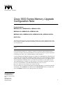
1
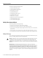
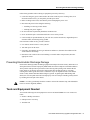
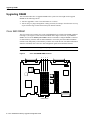
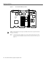
Text Part Number: 78-3636-03
Cisco 3600 Series Memory Upgrade
Configuration Note
Product Numbers:
MEM3600-4FS=, MEM3600-8FS=, MEM3600-16FS=
MEM3620-4D=, MEM3620-8D=, MEM3620-16D=
MEM3640-2X4D=, MEM3640-2X8D=, MEM3640-2X16D=, MEM3640-2X32D=
BOOT-3600=
This document describes how to upgrade dynamic random-access memory (DRAM) single in-line
memory modules (SIMMs), Flash-memory SIMMs, and read-only memory (ROM) in a Cisco 3620
or Cisco 3640 router.
Note In this document, the term “Cisco 3600 series” refers to both the Cisco 3620 and Cisco 3640
routers.
Use this document with the Cisco 3600 Series Hardware Installation Guide and the Regulatory
Compliance and Safety Information document for Cisco 3600 series routers. If you have questions
or need help, refer to the “Cisco Connection Online” section on page 23.
Cisco documentation and additional literature are available in a CD-ROM package, which ships with
your product. The Documentation CD-ROM, a member of the Cisco Connection Family, is updated
monthly. Therefore, it might be more current than printed documentation. To order additional copies
of the Documentation CD-ROM, contact your local sales representative or call customer service.
The CD-ROM package is available as a single package or as an annual subscription. You can also
access Cisco documentation on the World Wide Web at http://www.cisco.com,
http://www-china.cisco.com, or http://www-europe.cisco.com.
If you are reading Cisco product documentation on the World Wide Web, you can submit comments
electronically. Click Feedback in the toolbar and select Documentation. After you complete the
form, click Submit to send it to Cisco. We appreciate your comments.
Corporate Headquarters
Cisco Systems, Inc.
170 West Tasman Drive
San Jose, CA 95134-1706
USA
Copyright © 1999
Cisco Systems, Inc.
All rights reserved.
1
Safety Recommendations
This document contains the following sections:
•
•
•
•
•
•
•
•
•
•
Safety Recommendations, page 2
Tools and Equipment Needed, page 5
Removing the Cover, page 6
Upgrading DRAM, page 8
Upgrading Flash Memory, page 14
Upgrading the ROM, page 18
Replacing the Cover, page 21
Replacing Connections to the Router, page 22
Testing ROM Installation, page 23
Cisco Connection Online, page 23
Safety Recommendations
Follow these guidelines to ensure general safety:
•
•
•
Keep the area clear and dust-free during and after installation.
•
•
Wear safety glasses when working under any conditions that might be hazardous to your eyes.
Keep tools away from walk areas where you or others could fall over them.
Do not wear loose clothing that could get caught in the chassis. Fasten your tie or scarf and roll
up your sleeves.
Do not perform any action that creates a potential hazard to people or makes equipment unsafe.
Safety Warnings
Safety warnings appear throughout this publication in procedures that, if performed incorrectly, may
harm you. A warning symbol precedes each warning statement.
Warning Means danger. You are in a situation that could cause bodily injury. Before you work on
any equipment, be aware of the hazards involved with electrical circuitry and be familiar with
standard practices for preventing accidents. To see translations of the warnings that appear in this
publication, refer to the Regulatory Compliance and Safety Information document that accompanied
this device.
Waarschuwing Dit waarschuwingssymbool betekent gevaar. U verkeert in een situatie die
lichamelijk letsel kan veroorzaken. Voordat u aan enige apparatuur gaat werken, dient u zich bewust
te zijn van de bij elektrische schakelingen betrokken risico's en dient u op de hoogte te zijn van
standaard maatregelen om ongelukken te voorkomen. Voor vertalingen van de waarschuwingen die
in deze publicatie verschijnen, kunt u het document Regulatory Compliance and Safety Information
(Informatie over naleving van veiligheids- en andere voorschriften) raadplegen dat bij dit toestel is
ingesloten.
2 Cisco 3600 Series Memory Upgrade Configuration Note
Safety Warnings
Varoitus Tämä varoitusmerkki merkitsee vaaraa. Olet tilanteessa, joka voi johtaa ruumiinvammaan.
Ennen kuin työskentelet minkään laitteiston parissa, ota selvää sähkökytkentöihin liittyvistä
vaaroista ja tavanomaisista onnettomuuksien ehkäisykeinoista. Tässä julkaisussa esiintyvien
varoitusten käännökset löydät laitteen mukana olevasta Regulatory Compliance and Safety
Information -kirjasesta (määräysten noudattaminen ja tietoa turvallisuudesta).
Attention Ce symbole d'avertissement indique un danger. Vous vous trouvez dans une situation
pouvant causer des blessures ou des dommages corporels. Avant de travailler sur un équipement,
soyez conscient des dangers posés par les circuits électriques et familiarisez-vous avec les
procédures couramment utilisées pour éviter les accidents. Pour prendre connaissance des
traductions d’avertissements figurant dans cette publication, consultez le document Regulatory
Compliance and Safety Information (Conformité aux règlements et consignes de sécurité) qui
accompagne cet appareil.
Warnung Dieses Warnsymbol bedeutet Gefahr. Sie befinden sich in einer Situation, die zu einer
Körperverletzung führen könnte. Bevor Sie mit der Arbeit an irgendeinem Gerät beginnen, seien Sie
sich der mit elektrischen Stromkreisen verbundenen Gefahren und der Standardpraktiken zur
Vermeidung von Unfällen bewußt. Übersetzungen der in dieser Veröffentlichung enthaltenen
Warnhinweise finden Sie im Dokument Regulatory Compliance and Safety Information
(Informationen zu behördlichen Vorschriften und Sicherheit), das zusammen mit diesem Gerät
geliefert wurde.
Avvertenza Questo simbolo di avvertenza indica un pericolo. La situazione potrebbe causare
infortuni alle persone. Prima di lavorare su qualsiasi apparecchiatura, occorre conoscere i pericoli
relativi ai circuiti elettrici ed essere al corrente delle pratiche standard per la prevenzione di incidenti.
La traduzione delle avvertenze riportate in questa pubblicazione si trova nel documento Regulatory
Compliance and Safety Information (Conformità alle norme e informazioni sulla sicurezza) che
accompagna questo dispositivo.
Advarsel Dette varselsymbolet betyr fare. Du befinner deg i en situasjon som kan føre til
personskade. Før du utfører arbeid på utstyr, må du vare oppmerksom på de faremomentene som
elektriske kretser innebærer, samt gjøre deg kjent med vanlig praksis når det gjelder å unngå ulykker.
Hvis du vil se oversettelser av de advarslene som finnes i denne publikasjonen, kan du se i
dokumentet Regulatory Compliance and Safety Information (Overholdelse av forskrifter og
sikkerhetsinformasjon) som ble levert med denne enheten.
Aviso Este símbolo de aviso indica perigo. Encontra-se numa situação que lhe poderá causar danos
físicos. Antes de começar a trabalhar com qualquer equipamento, familiarize-se com os perigos
relacionados com circuitos eléctricos, e com quaisquer práticas comuns que possam prevenir
possíveis acidentes. Para ver as traduções dos avisos que constam desta publicação, consulte o
documento Regulatory Compliance and Safety Information (Informação de Segurança e
Disposições Reguladoras) que acompanha este dispositivo.
¡Advertencia! Este símbolo de aviso significa peligro. Existe riesgo para su integridad física. Antes
de manipular cualquier equipo, considerar los riesgos que entraña la corriente eléctrica y
familiarizarse con los procedimientos estándar de prevención de accidentes. Para ver una traducción
de las advertencias que aparecen en esta publicación, consultar el documento titulado Regulatory
Compliance and Safety Information (Información sobre seguridad y conformidad con las
disposiciones reglamentarias) que se acompaña con este dispositivo.
Varning! Denna varningssymbol signalerar fara. Du befinner dig i en situation som kan leda till
personskada. Innan du utför arbete på någon utrustning måste du vara medveten om farorna med
elkretsar och känna till vanligt förfarande för att förebygga skador. Se förklaringar av de varningar
som förkommer i denna publikation i dokumentet Regulatory Compliance and Safety Information
(Efterrättelse av föreskrifter och säkerhetsinformation), vilket medföljer denna anordning.
Cisco 3600 Series Memory Upgrade Configuration Note
3
Safety Recommendations
Warning Read the installation instructions before you connect the system to its power source.
Warning Only trained and qualified personnel should be allowed to install or replace this
equipment.
Warning Before working on a chassis or working near power supplies, unplug the power cord on
AC units; disconnect the power at the circuit breaker on DC units.
Warning Ultimate disposal of this product should be handled according to all national laws and
regulations.
Safety with Electricity
Warning The ISDN connection is regarded as a source of voltage that should be inaccessible to
user contact. Do not attempt to tamper with or open any public telephone operator (PTO)-provided
equipment or connection hardware. Any hardwired connection (other than by a nonremovable,
connect-one-time-only plug) must be made only by PTO staff or suitably trained engineers.
Warning Before working on equipment that is connected to power lines, remove jewelry (including
rings, necklaces, and watches). Metal objects will heat up when connected to power and ground and
can cause serious burns or weld the metal object to the terminals.
Warning To avoid electric shock, do not connect safety extra-low voltage (SELV) circuits to
telephone-network voltage (TNV) circuits. LAN ports contain SELV circuits, and WAN ports
contain TNV circuits. Both LAN and WAN ports may use RJ-45 connectors. Use caution when
connecting cables.
Warning Hazardous network voltages are present in WAN ports regardless of whether power to the
router is OFF or ON. To avoid electric shock, use caution when working near WAN ports. When
detaching cables, detach the end away from the router first.
Warning Before opening the chassis, disconnect the telephone-network cables to avoid contact
with telephone-network voltages.
Warning Do not work on the system or connect or disconnect cables during periods of lightning
activity.
Warning Do not touch the power supply when the power cord is connected. For systems with a
power switch, line voltages are present within the power supply even when the power switch is OFF
and the power cord is connected. For systems without a power switch, line voltages are present
within the power supply when the power cord is connected.
4 Cisco 3600 Series Memory Upgrade Configuration Note
Preventing Electrostatic Discharge Damage
Follow these guidelines when working on equipment powered by electricity:
•
Locate the emergency power-OFF switch in the room in which you are working. Then, if an
electrical accident occurs, you can quickly shut the power OFF.
•
•
Before working on the router, turn OFF the power and unplug the power cord.
Disconnect all power before doing the following:
— Installing or removing a router chassis
— Working near power supplies
•
•
•
Do not work alone if potentially hazardous conditions exist.
Never assume that power is disconnected from a circuit. Always check.
Look carefully for possible hazards in your work area, such as moist floors, ungrounded power
extension cables, and missing safety grounds.
If an electrical accident occurs, proceed as follows:
•
•
•
Use caution; do not become a victim yourself.
•
Determine if the victim needs rescue breathing or external cardiac compressions; then take
appropriate action.
Turn OFF power to the router.
If possible, send another person to get medical aid. Otherwise, determine the condition of the
victim and then call for help.
Preventing Electrostatic Discharge Damage
Electrostatic discharge (ESD) can damage equipment and impair electrical circuitry. ESD can occur
when printed circuit cards are improperly handled and can result in complete or intermittent failures.
Always follow ESD prevention procedures when removing and replacing cards. Ensure that the
router chassis is electrically connected to earth ground. Wear an ESD-preventive wrist strap,
ensuring that it makes good skin contact. Connect the clip to an unpainted surface of the chassis
frame to safely channel unwanted ESD voltages to ground. To guard against ESD damage and
shocks, the wrist strap and cord must be used properly. If no wrist strap is available, ground yourself
by touching the metal part of the chassis.
Caution For safety, periodically check the resistance value of the antistatic strap, which should be
between 1 and 10 megohms (Mohm).
Tools and Equipment Needed
You need the following tools and equipment to remove and install SIMMs in a Cisco 3600 series
router:
•
•
•
Number 1 Phillips screwdriver
ESD-preventive wrist strap
Antistatic mat
Cisco 3600 Series Memory Upgrade Configuration Note
5
Removing the Cover
Removing the Cover
To gain access to memory in a Cisco 3600 series router, you must first remove the chassis cover.
The following warning applies to routers with DC power supplies:
Warning Before performing any of the following procedures, ensure that power is removed from
the DC circuit. To ensure that all power is OFF, locate the circuit breaker on the panel board that
services the DC circuit, switch the circuit breaker to the OFF position, and tape the switch handle of
the circuit breaker in the OFF position.
Follow this procedure to remove the chassis cover:
Step 1
Turn OFF power to the router.
Step 2
Remove all network interface cables from the rear panel.
Step 3
If the router is rack- or wall-mounted, remove it from the rack or wall.
Step 4
Place the router so the front panel is closest to you. Remove the three screws located on
top of the cover near the front edge. (Figure 2 shows these screws for the Cisco 3620
cover, and Figure 3 shows the screws for the Cisco 3640 cover.) Set the screws aside in a
safe place.
Step 5
Lift the front edge of the cover about 1 inch (2.5 cm) above the chassis, as shown in
Figure 1.
Figure 1
Lifting the Cover
Screw
SY
ST
EM
RP
H7242
S
CO
N
AU
X
AC
TIV 0 1
RE E
AD
Y
PC
MC
IA
Step 6
1
0
Pull the cover toward you until the metal tabs on the rear edge separate from the chassis
bottom. (See Figure 2 for the Cisco 3620 and Figure 3 for the Cisco 3640.)
6 Cisco 3600 Series Memory Upgrade Configuration Note
Removing the Cover
Figure 2
Removing the Cisco 3620 Cover
Screw
SY
ST
EM
RP
H7241
S
CO
N
AU
X
AC
TIV 0 1
RE E
AD
Y
PC
MC
IA
Figure 3
1
0
Removing the Cisco 3640 Cover
Screw
SY
ST
EM
RP
H7043
S
CO
N
AU
X
AC
TIV 0 1
2
RE E
3
AD
Y
1
PC
MC
IA
Step 7
0
Lift the cover free and set it aside.
When you are ready to replace the cover, refer to the “Replacing the Cover” section on page 21.
If you are replacing DRAM SIMMs, continue with the next section, “Upgrading DRAM.” If you are
upgrading Flash memory, continue with the “Upgrading Flash Memory” section on page 14. If you
are upgrading your boot ROM, continue with the “Upgrading the ROM” section on page 18.
Cisco 3600 Series Memory Upgrade Configuration Note
7
Upgrading DRAM
Upgrading DRAM
This section describes how to upgrade DRAM on the system card. You might need to upgrade
DRAM for the following reasons:
•
•
You have upgraded to a new Cisco IOS feature set or release.
You are using very large routing tables or many protocols (for example, when the router is set up
as part of both a large external network and your internal network).
Cisco 3620 DRAM
The Cisco 3620 router contains four 72-pin single SIMM sockets (or banks) for DRAM, numbered
0 through 3. (See Figure 4.) Each socket can be filled with a single 32-bit-wide, 72-pin DRAM
SIMM. You can use the memory-size iomem software command to configure DRAM as a mixture
of shared memory, which is used for data transmitted or received by network modules and WAN
interface cards, and primary or main memory, which is reserved for the CPU. For further information
about this command, refer to the Cisco IOS configuration guides and command references.
Note DRAM in the Cisco 3620 supports only single-bank SIMMs and 32-bit operation.
Figure 4
Cisco 3620 DRAM SIMM Locations
1
2
3
H7317
0
DRAM SIMMs
8 Cisco 3600 Series Memory Upgrade Configuration Note
Cisco 3620 DRAM
Only certain combinations of DRAM SIMMs are permitted. These combinations are shown in
Table 1. (Memory configurations that are too small to run the Cisco IOS software are not shown.)
Table 1
Cisco 3620 32-Bit-Wide DRAM Configurations
Bank 0
(SIMM 0)
(MB)
Bank 1
(SIMM 1)
(MB)
Bank 2
(SIMM 2)
(MB)
Bank 3
(SIMM 3)
(MB)
Total
Memory
(MB)
4
4
4
–
12
4
81
–
–
12
4
4
8
–
16
4
16
–
–
20
8
4
–
–
12
8
8
–
–
16
8
16
–
–
24
8
8
4
–
20
8
8
8
–
24
8
8
4
4
24
8
8
4
8
28
8
8
8
4
28
8
8
16
–
32
16
–
–
–
16
16
4
–
–
20
16
8
–
–
24
16
16
–
-
32
16
16
4
–
36
16
16
8
–
40
16
16
4
4
40
16
16
8
4
44
16
16
4
8
44
16
16
8
8
48
16
16
16
–
48
16
16
16
4
52
16
16
4
16
52
16
16
16
8
56
16
16
8
16
56
16
16
16
16
64
1
8 = Single-bank SIMM, 8 MB in size.
Cisco 3600 Series Memory Upgrade Configuration Note
9
Upgrading DRAM
Cisco 3640 DRAM
The Cisco 3640 router contains four 72-pin SIMM sockets or banks for DRAM, numbered 0 through
3. (See Figure 5.) Each socket can be filled with a single 32-bit-wide, 72-pin DRAM SIMM. You
can configure DRAM in software as a mixture of shared memory, which is used for data transmitted
or received by network modules and WAN interface cards, and primary or main memory, which is
reserved for the CPU. For further information, refer to the Cisco IOS configuration guides and
command references.
You can configure DRAM in the Cisco 3640 router to be either 32 bits wide or 64 bits wide. The
64-bit mode can use both single-bank and dual-bank SIMMs. To use 64-bit mode, you must install
DRAM SIMMs in pairs of the same size.
Note In 32-bit mode, the router performs approximately 20 percent slower than when DRAM is
configured for 64-bit mode.
Figure 5
Cisco 3640 DRAM SIMM Locations
1
2
3
H7081
0
DRAM SIMMs
Only certain combinations of DRAM SIMMs are permitted. These combinations are shown in
Table 2 for 64-bit configurations, and in Table 3 for 32-bit configurations. (Memory configurations
that are too small to run the Cisco IOS software are not shown.)
Follow these rules to use 64-bit mode DRAM configuration:
•
The SIMMs in sockets 0 and 1 must be the same size (in MB) and have the same access time (in
nanoseconds).
•
•
The SIMMs in sockets 2 and 3 must be the same size and have the same access time.
The size of the SIMMs in sockets 2 and 3 must be less than or equal to the size of the SIMMs in
sockets 0 and 1.
10 Cisco 3600 Series Memory Upgrade Configuration Note
Cisco 3640 DRAM
Table 2
Cisco 3640 64-Bit-Wide DRAM Configurations
Bank 0
(SIMM 0)
(MB)
Bank 1
(SIMM 1)
(MB)
Bank 2
(SIMM 2)
(MB)
Bank 3
(SIMM 3)
(MB)
Total
Memory
(MB)
4
4
4
4
16
8
–
–
16
8 dual
–
–
16
8
8
4
4
24
8 dual
8 dual
4
4
24
8
8
8
8
32
8
8
8 dual
8 dual
32
8 dual
8 dual
8
8
32
8 dual
8 dual
8 dual
8 dual
32
16
16
–
–
32
16
16
4
4
40
16
16
8
8
48
16
16
8 dual
8 dual
48
16
16
16
64
32 dual
–
–
64
32 dual
32 dual
4
4
72
32 dual
32 dual
8
8
80
32 dual
32 dual
8 dual
8 dual
80
32 dual
32 dual
16
16
96
32 dual
32 dual
32 dual
32 dual
128
81
8 dual
2
16
32 dual
1
2
3
3
8 = Single-bank SIMM, 8 MB in size.
8 dual = Dual-bank SIMM, 8 MB in size.
32 dual = Dual-bank SIMM, 32 MB in size.
Table 3
Cisco 3640 32-Bit-Wide DRAM Configurations
Bank 0
(SIMM 0)
(MB)
Bank 1
(SIMM 1)
(MB)
Bank 2
(SIMM 2)
(MB)
Bank 3
(SIMM 3)
(MB)
Total
Memory
(MB)
4
8
–
–
12
4
16
–
–
20
4
4
4
–
12
4
4
8
–
16
8
4
–
–
12
8
16
–
–
24
8
8
4
–
20
8
8
8
–
24
Cisco 3600 Series Memory Upgrade Configuration Note
11
Upgrading DRAM
Table 3
Cisco 3640 32-Bit-Wide DRAM Configurations (continued)
Bank 0
(SIMM 0)
(MB)
Bank 1
(SIMM 1)
(MB)
Bank 2
(SIMM 2)
(MB)
Bank 3
(SIMM 3)
(MB)
Total
Memory
(MB)
8
8
4
8
28
8
8
8
4
28
8
8
16
–
32
16
–
–
–
16
16
4
–
–
20
16
8
–
–
24
16
16
4
–
36
16
16
8
–
40
16
16
4
8
44
16
16
4
16
52
16
16
8
4
44
16
16
8
16
56
16
16
16
–
48
16
16
16
4
52
16
16
16
8
56
DRAM Orientation
SIMMs are manufactured with a polarization notch to ensure proper orientation and alignment holes
to ensure proper positioning. Figure 6 shows the polarization notch and alignment holes on a SIMM
card. Cisco 3600 series DRAM SIMM cards are installed with the connector edge down, the
polarization notch near the front of the chassis, and the component side facing the right side of the
chassis.
Caution To avoid damaging ESD-sensitive components, observe all ESD precautions. To avoid
damaging the motherboard, avoid using excessive force when you remove or replace SIMMs.
Figure 6
Cisco 3600 Series DRAM SIMM
H2407
Alignment holes
Connector edge
12 Cisco 3600 Series Memory Upgrade Configuration Note
Polarization notch
Removing DRAM SIMMs
Removing DRAM SIMMs
Follow these steps to remove DRAM SIMMs:
Step 1
Find the DRAM SIMM sockets on the motherboard, as shown in Figure 4 or Figure 5.
Caution Handle SIMMs by the card edges only. SIMMs are ESD-sensitive components and can be
damaged by mishandling.
Step 2
Remove one SIMM at a time, beginning with the SIMM in bank 3. To lift the SIMM out
of its socket, pull the locking spring clips on both sides outward and tilt the SIMM toward
the right side of the chassis, free of the clips. (See Figure 7.)
Figure 7
Removing DRAM SIMMs
Top view
Front of chassis
H7038
2. Push the top of the
SIMM forward and down.
SIMM
polarization
notch
1. Pull the locking spring clips outward.
Step 3
Hold the SIMM by the edges with your thumb and index finger and lift it out of the socket.
Place the removed SIMM in an antistatic bag to protect it from ESD damage.
Step 4
Repeat Step 2 and Step 3 for each SIMM.
Installing DRAM SIMMs
Follow this procedure to install DRAM SIMMs:
Step 1
Find the DRAM SIMM sockets on the motherboard, as shown in Figure 4 or Figure 5.
Caution Handle SIMMs by the card edges only. SIMMs are ESD-sensitive components and can be
damaged by mishandling.
Step 2
Hold the SIMM with the polarization notch on the right, near the front of the chassis, and
the component side away from you, with the connector edge at the bottom. (See
Figure 6.)
Cisco 3600 Series Memory Upgrade Configuration Note
13
Upgrading Flash Memory
Step 3
Beginning with bank 0, insert the SIMM into the connector slot at an angle, tilted toward
the right side of the chassis. Rock the SIMM into a vertical position (see Figure 8), using
the minimum amount of force required. When the SIMM is properly seated, the socket
guide posts fit through the alignment holes, and the connector springs click into place.
Step 4
Ensure that each SIMM is straight and that the alignment holes (as shown in Figure 7)
line up with the plastic guides on the socket.
Figure 8
Installing DRAM SIMMs
View from front of chassis
1. Insert the SIMM into the socket
at an angle from vertical.
2. Push the top of the SIMM
down and back.
3. The socket guide posts fit through
the holes in the SIMM.
H7037
4. The locking springs clip the back
of the SIMM.
Caution It is normal to feel some resistance, but do not use excessive force on the SIMM, and do
not touch the surface components.
Step 5
Repeat Step 2 through Step 4 for each SIMM.
If you are finished replacing SIMMs, continue with the “Replacing the Cover” section on page 21.
Upgrading Flash Memory
Cisco 3600 series routers contain one or two 80-pin Flash-memory SIMMs for storing the system
software image. These SIMMs are not interchangeable with DRAM SIMMs. You can upgrade Flash
memory by replacing an existing SIMM with a SIMM that has greater capacity, or by adding a
SIMM to the second Flash-memory socket.
SIMMs are manufactured with a polarization notch to ensure proper orientation and alignment holes
to ensure proper positioning, similar to those shown in Figure 9. Cisco 3600 series Flash SIMM
cards are installed with the connector edge down, the polarization notch near the front of the chassis,
and the component side facing the right side of the chassis.
14 Cisco 3600 Series Memory Upgrade Configuration Note
Removing Flash-Memory SIMMs
Figure 9
Flash-Memory SIMM Orientation and Alignment
H2407
Alignment holes
Connector edge
Polarization notch
Caution To avoid damaging ESD-sensitive components, observe all ESD precautions. To avoid
damaging the motherboard, avoid using excessive force when you remove or replace SIMMs.
Removing Flash-Memory SIMMs
Follow this procedure to remove an existing Flash-memory SIMM:
Step 1
Put on an ESD-preventive wrist strap and ensure that it makes good contact with your
skin. Connect the equipment end of the wrist strap to the metal backplate of the chassis,
avoiding contact with connectors.
Step 2
Find the Flash-memory SIMM sockets on the router motherboard. (See Figure 10 and
Figure 11.)
Cisco 3620 Flash Memory Locations
1
0
H7318
Figure 10
Flash memory SIMMs
Cisco 3600 Series Memory Upgrade Configuration Note
15
Upgrading Flash Memory
Figure 11
Cisco 3640 Flash Memory Locations
0
H7082
1
Flash memory SIMMs
Caution Handle SIMMs by the card edges only. SIMMs are ESD-sensitive components and can be
damaged by mishandling.
Step 3
To lift the Flash-memory SIMM out of its socket, pull the locking spring clips on both
sides outward and tilt the SIMM toward the left side of the chassis, free of the clips. (See
Figure 12.)
16 Cisco 3600 Series Memory Upgrade Configuration Note
Installing Flash-Memory SIMMs
Figure 12
Removing Flash-Memory SIMMs
Top view
1. Pull the locking spring clips outward.
2. Push the top of the SIMM
forward and down.
SIMM polarization notch
H7085
Front of chassis
Installing Flash-Memory SIMMs
Follow this procedure to install Flash-memory SIMMs:
Step 1
Find the Flash-memory SIMM sockets on the Cisco 3600 series motherboard.
(See Figure 10 and Figure 11.)
Caution Handle SIMMs by the card edges only. SIMMs are ESD-sensitive components and can be
damaged by mishandling.
Step 2
Hold the SIMM with the polarization notch on the right and the component side away
from you, with the connector edge at the bottom.
Step 3
Referring to Figure 13, insert the Flash-memory SIMM into its connector slot at an angle,
tilted toward the left side of the chassis. Rock the SIMM into a vertical position, using the
minimum amount of force required. When the SIMM is properly seated, the socket guide
posts fit through the alignment holes, and the locking springs click into place. Use the
minimum amount of force required.
Cisco 3600 Series Memory Upgrade Configuration Note
17
Upgrading the ROM
Figure 13
Inserting Flash-Memory SIMMs
View from front of chassis
1. Insert the SIMM into the socket
at an angle from vertical.
2. Push the top of the SIMM
down and back.
H7084
3. The socket guide posts fit through
the holes in the SIMM.
4. The locking springs clip the back
of the SIMM.
Caution It is normal to feel some resistance, but do not use excessive force on the SIMM, and do
not touch the surface components.
Step 4
Check the alignment of each SIMM to make sure that it is straight and that the alignment
holes are lined up with the plastic socket guides.
If you are finished replacing SIMMs, continue with the “Replacing the Cover” section on page 21.
Upgrading the ROM
To upgrade the Cisco 3600 series firmware to a new ROM monitor, you must replace the existing
ROM.
In addition to the tools described in the “Tools and Equipment Needed” section on page 5, you also
need:
•
•
A ROM extraction tool or small flat-blade screwdriver
Needlenose pliers
Caution Correct placement of the ROM is crucial. If improperly positioned, the new component
could be damaged when the router is powered on. Read all instructions before proceeding. To
prevent damage to the ROM from ESD, follow the ESD procedures described in the “Preventing
Electrostatic Discharge Damage” section on page 5. Be careful not to damage or scratch the printed
circuit card under the ROM.
18 Cisco 3600 Series Memory Upgrade Configuration Note
Upgrading the ROM
Follow these steps to replace the ROM:
Step 1
Cisco 3620 ROM Location
H7319
Figure 14
Locate the ROM on the motherboard. (See Figure 14 and Figure 15.)
ROM
Step 2
Carefully remove the old ROM with a ROM extraction tool or a small flat-blade
screwdriver, and set it aside.
Step 3
Insert the new ROM in its socket in the orientation shown in Figure 14 or Figure 15, being
careful not to bend or crush any of the bottom pins. To straighten out a bent pin, use
needlenose pliers. Align the notch in the new ROM with the notch in the ROM socket,
ignoring the orientation of the label.
Caution The notch on the ROM must match the notch on the socket on the card. Installing the ROM
backward will damage it.
When you are finished replacing the ROM, continue with the “Replacing the Cover” section on
page 21.
Cisco 3600 Series Memory Upgrade Configuration Note
19
Upgrading the ROM
Figure 15
Cisco 3640 ROM Location
H7083
ROM
20 Cisco 3600 Series Memory Upgrade Configuration Note
Replacing the Cover
Replacing the Cover
After you finish replacing memory, follow these steps to replace the cover:
Step 1
Place the chassis bottom so the front panel is closest to you.
Step 2
Hold the cover so the tabs at the rear of the cover are aligned with the chassis bottom, as
shown in Figure 16 and Figure 17.
Step 3
Push the cover toward the rear, making sure that the cover tabs fit under the chassis back
panel, and the back panel tabs fit under the cover.
Step 4
Lower the front of the cover onto the chassis, making sure that the cover side tabs fit under
the chassis side panels, and the chassis tabs fit under the cover side panels.
Step 5
Fasten the cover with the three screws you set aside earlier.
Step 6
Reinstall the chassis on a rack, wall, desktop, or table.
Step 7
Reinstall network interface cables, as described in the following section, “Replacing
Connections to the Router.”
Figure 16
Replacing the Cisco 3620 Cover
Chassis cover
Chassis
tabs
Cover
tabs
Cover
tabs
SY
ST
EM
RP
H7243
S
CO
N
AU
X
AC
TIV 0 1
RE E
AD
Y
Front panel
Chassis bottom
PC
MC
IA
1
0
Cisco 3600 Series Memory Upgrade Configuration Note
21
Replacing Connections to the Router
Figure 17
Replacing the Cisco 3640 Cover
Chassis cover
Cover
tabs
Chassis
tabs
Cover tabs
SY
ST
EM
RP
H7044
S
CO
N
AU
X
AC
TIV 0 1
2
RE E
3
AD
Y
Side tabs
Front panel
1
PC
MC
IA
0
Chassis bottom
Replacing Connections to the Router
Follow these steps to make final connections to the router:
Warning Read the installation instructions before you connect the system to its power source.
Step 1
Replace all network connections.
Step 2
If you have an AC-powered router, plug the power cord into a 3-terminal, single-phase
power source that provides power within the acceptable range (100 to 240 VAC, 50 to
60 Hz).
If you have a DC-powered router, remove the tape from the circuit breaker switch handle
and reinstate power by moving the handle of the circuit breaker to the ON position.
Step 3
Turn ON the power switch. The power LED on the front panel of the router should go
ON.)
Step 4
Check the OK LED on the right side of the front panel to verify that it goes ON after a
few seconds delay when booting.
Step 5
If you have problems, and you replaced the ROM, see the next section, “Testing ROM
Installation.” Otherwise, see the “Cisco Connection Online” section on page 23.
22 Cisco 3600 Series Memory Upgrade Configuration Note
Testing ROM Installation
Testing ROM Installation
If you installed a new ROM, the router should boot into the ROM monitor or Cisco IOS.
Follow these steps if you suspect that the ROM is inserted incorrectly:
Step 1
Remove the cover, as described in the “Removing the Cover” section on page 6.
Step 2
Gently remove the old ROM with a ROM extraction tool or a small flat-blade screwdriver,
and set it aside.
Step 3
Use needlenose pliers to straighten any bent pins on the ROM.
Step 4
Insert the new ROM in its socket in the orientation shown in Figure 14 or Figure 15, being
careful not to bend or crush any of the bottom pins. Align the notch in the new ROM with
the notch in the ROM socket, ignoring the orientation of the label.
Step 5
Replace the cover, as described in the “Replacing the Cover” section on page 21.
Step 6
Try booting the router again.
If the problem persists, see the next section, “Cisco Connection Online.”
Cisco Connection Online
Cisco Connection Online (CCO) is Cisco Systems’ primary, real-time support channel. Maintenance
customers and partners can self-register on CCO to obtain additional information and services.
Available 24 hours a day, 7 days a week, CCO provides a wealth of standard and value-added
services to Cisco’s customers and business partners. CCO services include product information,
product documentation, software updates, release notes, technical tips, the Bug Navigator,
configuration notes, brochures, descriptions of service offerings, and download access to public and
authorized files.
CCO serves a wide variety of users through two interfaces that are updated and enhanced
simultaneously: a character-based version and a multimedia version that resides on the World Wide
Web (WWW). The character-based CCO supports Zmodem, Kermit, Xmodem, FTP, and Internet
e-mail, and it is excellent for quick access to information over lower bandwidths. The WWW version
of CCO provides richly formatted documents with photographs, figures, graphics, and video, as well
as hyperlinks to related information.
You can access CCO in the following ways:
•
•
•
•
•
WWW: http://www.cisco.com
WWW: http://www-europe.cisco.com
WWW: http://www-china.cisco.com
Telnet: cco.cisco.com
Modem: From North America, 408 526-8070; from Europe, 33 1 64 46 40 82. Use the
following terminal settings: VT100 emulation; databits: 8; parity: none; stop bits: 1; and
connection rates up to 28.8 kbps.
For a copy of CCO’s Frequently Asked Questions (FAQ), contact [email protected]. For
additional information, contact [email protected].
Cisco 3600 Series Memory Upgrade Configuration Note
23
Cisco Connection Online
Note If you are a network administrator and need personal technical assistance with a Cisco
product that is under warranty or covered by a maintenance contract, contact Cisco’s Technical
Assistance Center (TAC) at 800 553-2447, 408 526-7209, or [email protected]. To obtain general
information about Cisco Systems, Cisco products, or upgrades, contact 800 553-6387,
408 526-7208, or [email protected].
Use this document with the Cisco 3600 Series Hardware Installation Guide and the Regulatory Compliance and Safety Information document for Cisco 3600 series routers.
Access Registrar, AccessPath, Any to Any, AtmDirector, CCDA, CCDE, CCDP, CCIE, CCNA, CCNP, CCSI, CD-PAC, Centri, Cisco Certified Internetwork Expert logo, CiscoLink, the
Cisco Management Connection logo, the Cisco NetWorks logo, the Cisco Powered Network logo, Cisco Systems Capital, the Cisco Systems Capital logo, the Cisco Technologies logo,
ControlStream, Fast Step, FireRunner, Gigastack, IGX, JumpStart, Kernel Proxy, LoopRunner, MGX, Natural Network Viewer, NetSonar, Network Registrar, Packet, PIX, Point and Click
Internetworking, Policy Builder, Precept, RouteStream, Secure Script, SMARTnet, SpeedRunner, Stratm, StreamView, The Cell, TrafficDirector, TransPath, ViewRunner, VirtualStream,
VlanDirector, Workgroup Director, and Workgroup Stack are trademarks; Changing the Way We Work, Live, Play, and Learn, Empowering the Internet Generation, The Internet Economy,
and The New Internet Economy are service marks; and BPX, Catalyst, Cisco, Cisco IOS, the Cisco IOS logo, Cisco Systems, the Cisco Systems logo, the Cisco Systems Cisco Press logo,
Enterprise/Solver, EtherChannel, FastHub, ForeSight, FragmentFree, IOS, IP/TV, IPX, LightStream, LightSwitch, MICA, NetRanger, Phase/IP, Registrar, StrataSphere, and StrataView Plus
are registered trademarks of Cisco Systems, Inc. in the U.S. and certain other countries. All other trademarks mentioned in this document are the property of their respective owners.
(9902b R)
Copyright © 1999, Cisco Systems, Inc.
All rights reserved.
24 Cisco 3600 Series Memory Upgrade Configuration Note