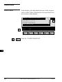
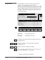
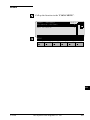
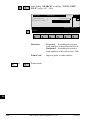
1
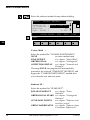
TPS - System 1000
Programs
Version 2.2
TCA
180
0
1000Z01
USER'S MANUAL
English
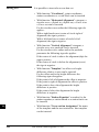
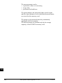
Congratulations on your purchase of your programs
for a TPS - System 1000 !
In order to use the software correctly and reliably, you
must follow the instructions given in the user manual or
in the on-line help system. You must also adhere to the
directions given in the user manual for the product with
which you are using the software.
The rights and responsibilities accruing in respect to
Leica as a result of acquisition of the software are set
out in the Leica Software License Agreement.
To secure your rights with regard to the software
acquired, it is essential that you follow the directions
given on the Leica Software - Support Registration
Card.
2
TPS-System 1000 Programs-2.3.1en
© Leica
TPS - System 1000
Programs
Product identification Enter your programs' version number in your manual
and always refer to this information when you need to
contact your agency or authorized service workshop.
Version number:
© Leica
TPS-System 1000 Programs-2.3.1en
3
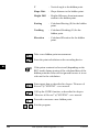
Symbols used in this Manual
The symbols used in this User's Manual have the
following meanings:
DANGER :
Indicates an imminently hazardous situation which, if
not avoided, will result in death or serious injury.
WARNING :
Indicates a potentially hazardous situation or an
unintended use which, if not avoided, could result in
death or serious injury.
CAUTION :
Indicates a potentially hazardous situation or an
unintended use which, if not avoided, may result in
minor or moderate injury and / or appreciable material,
financial and environmental damage.
Important paragraphs which must be adhered to in
practice as they enable the product to be used in a
technically correct and efficient manner.
4
TPS-System 1000 Programs-2.3.1en
© Leica
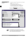
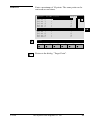
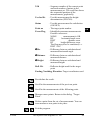
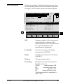
View of chapters
Contents
© Leica
6 CO
Introduction
11 IN
General notes
23 GN
Orientation and Height Transfer
27 OH
Resection
39 RE
Tie Distance
49 TD
Stakeout
59 SO
Free Station
79 FS
Reference Line
93 RL
Remote Height
105 RH
Hidden Point
111 HP
Area (Computation of Area)
117 AR
Sets of Angles
129 SA
Traverse
147 TR
Local Resection
165 LR
Road Line
171 RO
COGO
205 CG
Road Plus
249 RP
File Editor
303 FE
Monitoring
333 MO
Index
341 IX
TPS-System 1000 Programs-2.3.1en
5
Contents
Introduction
General
Installation in the PC
CO
Hardware and software required
Rules for naming files
Loading files into the TPS1000 instruments
Loading system texts
Loading application programs
Licence code
Solving problems
General notes
Units in this manual
Preparation
Settings
Data exchange
Using the program
12
15
17
19
20
21
21
23
23
23
23
24
24
Instrument field setup
Calling up the program
Designation of keys
Target eccentricity
24
25
26
26
Orientation and Height Transfer
Introduction
Target Point
27
27
28
Point List
29
Measure Mode
Calculation
30
31
More Information
Plot
Configuration
Configuration Editor
Dual-face Measurement
Log file
Resection
Introduction
Station Data
Target Point
Measure Mode
Calculation
Configuration
Configuration Editor
Dual-face Measurement
Log File
6
11
11
12
TPS-System 1000 Programs-2.3.1en
32
34
35
35
37
37
39
39
40
41
42
43
45
45
47
47
© Leica
Tie Distance
Introduction
Measure Mode
Results
Configuration
Configuration Editor
Dual-face Measurement
Log File
Stakeout
Introduction
Search Point
Coarse Positioning
Line Offset
Orthogonal
Azimuth and Distance
Stakeout
Polar Stakeout
Orthogonal Stakeout
Stakeout with auxiliary points
Stakeout from Coordinate Differences
Select Stakeout Method
Plot
Configuration
Log File
Free Station
Introduction
Station Data
Target Point
55
56
57
59
59
59
60
60
62
64
66
66
68
70
72
74
75
76
77
79
79
80
80
Point List
81
Measure Mode
Calculation
82
83
More Information
Plot
Configuration
Configuration Editor
Dual-face Measurement
Log File
Reference Line
Introduction
Baseline Points
Determine Base Points
Measure a Base Point
© Leica
49
49
51
53
55 CO
85
87
88
88
90
90
93
93
95
95
96
Define Reference Line
Results Reference Line
Configuration
98
99
101
Configuration Editor
Log File
101
103
TPS-System 1000 Programs-2.3.1en
7
CO
Remote Height
Introduction
Measure Base Point
Measure Remote Point
Configuration
105
105
106
108
110
Hidden Point
Introduction
Configuration
Measure Rod
Results
111
111
112
114
115
Area (Computation of Area)
Introduction
Measure Mode
117
117
118
Straight line
Arcs
Calculation
Plot
Configuration
Configuration Editor
Dual-face Measurement
Log File
Sets of Angles
Introduction
Sets Menu
Sets menu - view
Measure Mode
Calculate Mode
Examples and used formulae
Configuration
Configuration Editor
Log File
Traverse
Introduction
Traverse Menu
Traverse menu
New traverse
Occupy station
Traverse Point / Sideshot Point
Close traverse
Plot
Configuration
Configuration Editor
Dual-face Measurement
Multiple Measurement
Log File
8
TPS-System 1000 Programs-2.3.1en
118
120
123
124
125
125
126
127
129
129
130
130
131
135
140
143
143
145
147
147
148
148
149
153
155
156
159
160
160
161
161
163
© Leica
Local Resection
Introduction
Station Data
Target Points
Calculation
Configuration
Configuration Editor
Dual-face Measurement
Road line
Introduction
Program concept
Alignment
Selection of files
Checking files
Program flow
Chainage and centre-line offset
Cross sections
Stakeout
X-section Check
Configuration
Configuration Editor
Log File
Data format
Hz-alignment
169
170
171
171
174
175
175
176
178
178
180
183
184
188
188
190
192
192
The Road - Data Entry program
204
COGO
Introduction
Configuration
Function selection (COGO Menu)
Inverse (polar calculation)
Traverse
205
205
207
208
209
212
Defining direction by magnetic bearing
Defining direction by Azimuth
Defining horizontal distance
Intersections
Bearing-Bearing Intersection
Bearing-Distance Intersection
Distance-Distance Intersection
Offsets
Distance-Offset
Orthogonal point calculation
Three Point Arc
Road Plus
Introduction
Alignment Definition
Data Files
Creating Data Files
Program Overview
© Leica
165
165
166
167
168 CO
169
TPS-System 1000 Programs-2.3.1en
214
216
218
221
222
227
233
237
238
241
246
249
249
249
249
252
252
9
Getting Started
Configuration
Select Alignment Files
253
254
256
Vertical Alignment File
Horizontal Alignment File
Cross Section/template File
Cross Section Assignment File
Station Equation File
File Checking
CO
257
257
257
259
262
263
Stakeout Using Horizontal Offset
264
Preparing for the example
Select Template point and offset
Stakeout and Record point
264
270
273
Horizontal Offset Stake Out Summary
280
Start ROADPLUS & Set Configuration Options
Select Alignment Files
Set offset value and select point to stakeout
Stakeout the point
Select new chainage
Slope Staking
Reference Point
Data Formats
Horizontal Alignment
Vertical Alignment
Cross Sections
Cross Section Assignments
Station Equations
Log File
File Editor
Introduction
Creation of files
Editing files
Open file
10
280
281
282
283
284
285
289
291
291
294
296
298
300
301
303
303
303
304
305
Coordinates
Horizontal Alignment
Vertical Alignment
Template
Station Equation
Cross-section Assignment
306
311
317
321
325
329
Monitoring
Main menu
Selecting points
Measurement menu
Selecting the points to be measured
Timer selection
Point measurement
End monitoring
333
335
336
337
338
339
340
340
Index
341
TPS-System 1000 Programs-2.3.1en
© Leica
Introduction
General
The electronic theodolites and total stations in the TPS
System 1000 are equipped with programs for
processing field data and control-point coordinates. The IN
systems are therefore highly functional and classical
survey tasks are simplified appreciably.
When delivered, the instruments are already equipped
for the following standard applications:
- Orientation and height transfer
- Resection
- Tie distance
- Stakeout
- Free-station survey (Licence code required)
In addition, the following applications are delivered on
diskette:
- Reference line / building alignment
- Remote height
- Hidden points
- Computation of area
- Sets of angles
- Traverse
- Local resection
- Roadline
- File Editor
- Road Plus
- COGO
- Monitoring
This list is extended continuously. Find actual
information in file README.TXT on diskette.
The additional application programs can be loaded into
the instrument, but can only be run as a demonstration
version in which certain functions are disabled. Full
functionality can be obtained with a licence code,
available from your Leica agency, where you can also
obtain information about the newest programs available
in the ongoing applications-software development
© Leica
TPS-System 1000 Programs-2.3.1en
11
project.
All installation programs and applications are supplied
on normal 3 1/2" diskettes.
For optimal use of the programs and instruments read
this manual carefully.
IN
Installation in the PC
Hardware and software
required
The hardware and software used to transfer the
individual program packages must meet the following
requirements:
• IBM-compatible PC, 386 or higher
• 4 MB RAM
• 3.5" floppy-disk drive
• RS 232 interface, including interface cable for Leica
survey instruments (stock no. 563625)
• MS DOS 5.0 or higher
• MS Windows 3.1
Four diskettes are supplied with each instrument:
• disk 1 = SYSTEM FIRMWARE
• disk 2 = Programs and Languages
• disk 3 = TPS-WORKBENCH
• disk 4 = RCS 1000
More information can be found in the file
README.TXT on each diskette.
Recommended installation procedure:
1. TPS-WORKBENCH (disk 3)
2. SYSTEM FIRMWARE (disk 1)
3. Programs and languages (disk 2)
4. RCS 1000 (disk 4)
12
TPS-System 1000 Programs-2.3.1en
© Leica
On the diskette bearing the label
TPS 1000/2000/5000
TPS-WORKBENCH
is the PC software needed to install applications or
foreign-language texts on the TPS1000 instruments.
IN
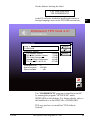
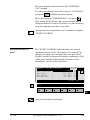
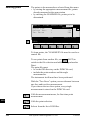
Workbench TPS Tools 2.21
Installation
Installation TPS
Install to:
C:\LEICA.WB
Continue
Exit
Installation Options:
ü TPS Software Upload
ü RCS 1000 Controller Upload
ü TPS Code Development
ü Software Radio Configuration
ü TPS PC to MC / MC to PC
Installation Drive:
Space Required:
Space Available:
378 KB
57 KB
157 KB
123 KB
277 KB
Directory...
C:
1697 KB
...... KB
Pause
Exit F3
The "WORKBENCH" program is installed in the PC
by running the program "SETUP.EXE" under
WINDOWS on the diskette. For further details, refer to
the handbook or to the HELP file of WINDOWS.
TPS-user just have to install the "TPS Softwae
Upload".
© Leica
TPS-System 1000 Programs-2.3.1en
13
The diskette bearing the label
TPS 1000
SYSTEM FIRMWARE
contains the necessary system software for the TPS
1000 instrument:
• theodolite system software
• ATR system software
• EDM system software
IN
The diskette bearing the label
TPS 2000/5000
SYSTEM FIRMWARE
contains the necessary system software for the
TPS2000/5000 instrument:
• theodolite system software
• ATR system software
• EDM system software
The diskette bearing the label
TPS 1000/2000/5000
Programs and Languages
contains:
• all applications (both the standard ones and the
additional ones),
• the appropriate text files for the languages available.
The text for the languages available are also included
for the TPS1000 system software.
The diskette bearing the label
TPS 1000/2000/5000
RCS 1000
contains the remote control software:
• for RCS 1000 based on CR233/333
• for RCS 1000 based on GPC1
14
TPS-System 1000 Programs-2.3.1en
© Leica
Rules for naming files
The files are named in accordance with the following
rules:
Application programs:
?????
VVV
PRG
Maximum of 5 characters for name of
application
3 characters for version (release) number
Identification tag for loadable application
Text files:
?????
VVV
L
?????VVV.PRG
IN
?????VVV.LSS
identical name of relevant application
identical version (release) number of relevant
application
Identification tag for text file of application
SS Identification tag for language
SS =>
EN
English
GE
German
FR
French
SP
Spanish
System texts:SYS?_VVV._SS
SYS?_ Seven text files (SYS1_ ... SYS7_)
VVV
Version (release) number of system texts
Identification tag for text file of system
SS
Identification tag for language
SS =>
GE
German
FR
French
SP
Spanish
© Leica
TPS-System 1000 Programs-2.3.1en
15
After the installation is complete, you will find the
following files in the subdirectory in your PC:
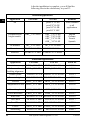
Standard applications
Application
IN
File name
All
Text file
Remarks
prtxtVVV.LEN
prtxtVVV.LGE
prtxtVVV.LFR
prtxtVVV.LSP
Texts common
to all
applications
English
German
French
Spanish
Orientation and
height transfer
ORI__VVV.PRG
ORI__VVV.LEN
ORI__VVV.LGE
ORI__VVV.LFR
ORI__VVV.LSP
Tie distance
TIE__VVV.PRG
TIE_VVV.LENetc.
Resection
RESECVVV.PRG
RESECVVV.LENetc.
Stakeout
STAKEVVV.PRG
STAKEVVV.LENetc.
Additional applications
Application
File name
Free-station survey
FREE_VVV.PRG
FREE_VVV.LEN etc.
663156
Reference line /
building alignment
REFL_VVV.PRG
REFL_VVV.LEN etc.
663198
Hidden points
HDNPTVVV.PR
HDNPTVVV.LEN etc.
663213
Remote height
REMHTVVV.PR REMHTVVV.LEN etc.
663200
Traverse
Text file
Stock no.
TRAV_VVV.PRG
TRAV_VVV.LEN etc.
663197
Computation of area AREA_VVV.PRG
AREA_VVV.LEN etc.
663196
Sets of angles
SETS_VVV.PRG
SETS_VVV.LEN etc.
663199
Local Resection
LRES_VVV.PRG
LRES_VVV.LEN etc.
663267
Road Line
ROADLVVV.PR ROADLVVV.LEN etc.
663216
File Editor
FILEDVVV.PRG
FILEDVVV.LEN etc.
663217
Road Plus
RPLUSVVV.PRG
RPLUSVVV.LEN etc.
663218
COGO
COGO_VVV.PRG
COGO_VVV.LEN etc.
664401
MONIT222.PRG
MONIT222.LEN etc.
664411
Monitoring
16
TPS-System 1000 Programs-2.3.1en
© Leica
Loading files into the
TPS1000 instruments
Applications, and system- and application texts, are
loaded into the TPS1000 by means of the "TPS
SOFTWARE UPLOAD" program.
Use the interface cable 563 625 to connect the
TPS1000 to the serial interface COM1 or COM2 on the IN
PC.
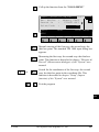
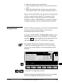
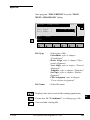
Start the "TPS SOFTWARE UPLOAD" program with a
double-click from the WINDOWS program manager.
Select the command "Sensor/Settings" and inspect the
interface selected and the baud rate. The baud rate
should be set to the maximum. The baud rate for the
TPS1000 instrument is set automatically.
TPS 1000 Settings
COM-Port:
OK
COM1
Cancel
Baudrate
4800
Help
9600
19200
© Leica
TPS-System 1000 Programs-2.3.1en
17
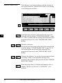
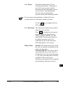
Switch the instrument off! Select the command "View
Applications + System" to inspect the connection to the
instrument. The instrument switches itself on again and
establishes the connection. The display of the
applications available on the instrument shows that the
connection was successful. If it was not successful, read
section "Solving problems".
IN
View Applications & System
General
Environment
Name
Version
Applications
Art.No.
Language
Licence Code
FreeSt_Ori_Res
V 2.20
663156
ENGLISH
<none>
—
TieDistance
V 2.20
663152
ENGLISH
<none>
—
Stakeout
V 2.20
663155
ENGLISH
<none>
—
Close
18
Help
TPS-System 1000 Programs-2.3.1en
© Leica
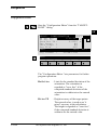
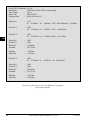
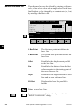
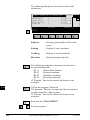
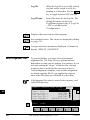
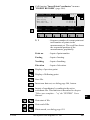
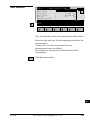
Loading system texts
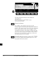
- Select the command "Transfer files" in the "Utilities"
menu ,
- Mark "System Language",
- select relevant drive under "Directories",
- select desired language under "Language" and
- mark relevant file under "Components".
IN
Then press the Transfer key to start the transfer.
The progress of the transfer is shown in a bar diagram.
Transfer
Component Type
System Software
ü
Directories:
i:\software\tps1000\V_2_20
System Language
i:\
software
tps1000
V_2_20
Application Program
EDM/ATR Firmware
Language:
Transfer
Cancel
Settings ...
Help
Drives:
i:
ENGLISH-T
Components:
System Language (ENGLISH-T Version 2.20)
Afterwards, enter the language on the instrument (see
section "Configuration" of "System" - user manual).
The English system texts are part of the system software
and can be neither loaded nor erased.
© Leica
TPS-System 1000 Programs-2.3.1en
19
Loading application
programs
IN
- Select the command "Transfer files" in the "Utilities"
menu ,
- Mark "Application Program",
- select relevant drive under "Directories",
- select desired language under "Language" and
- mark desired program(s) under "Components".
Then press the Transfer key to start the transfer.
The progress of the transfer is shown in a bar diagram.
Transfer
Component Type
Directories:
System Software
i:\software\tps1000\V_2_20
System Language
ü
i:\
software
tps1000
V_2_20
Application Program
EDM/ATR Firmware
Language:
Transfer
Cancel
Settings ...
Help
Drives:
i:
ENGLISH-T
Components:
TPS-Application
TPS-Application
TPS-Application
TPS-Application
TPS-Application
TPS-Application
Area (V2.20)
COGO (V2.20)
FreeSt_Ori_Res (V2.20)
HiddenPoint (V2.20)
LocalRes (V2.20)
RefLine (V2.20)
It is absolutely necessary that the program files
(*.prg) are be in the same directory as the language
files (*.LSS) and the Prtxt220.LSS file.
20
TPS-System 1000 Programs-2.3.1en
© Leica
Licence code
When an additional application is first started up, a
licence code is requested, so that the application will be
fully functional. Without this licence code, you can run
the applications as a demonstration version, but you will
not be able to calculate and store the results.
The licence code is available from your Leica agency,
who will inform you about licence fees for additional
applications. Details of the licence agreement are given
in the registration card, which is a part of the "System"
manual.
To expedite formalities, please fill in a copy of the form
at the end of this section and fax it to your local Leica
agency.
Solving problems
1. Instrument does not switch on when "Utilities/View
Applications + System..." option is selected.
Inspect the cable connections and that the serial
interface COM1 or COM2 has been set correctly.
2. Instrument does not switch to "ON-LINE-MODE
(GeoCOM)" mode when "Utilities/View
Applications + System..." option is selected.
Make sure that the instrument is switched off before
the "Utilities/View Applications + System..." option
is activated.
3. Instrument does not switch to "ON-LINE-MODE
(GeoCOM)" mode when "Utilities/View
Applications + System..." option is selected;
"MEASURE & RECORD" menu or another autostart
application is displayed instead.
© Leica
TPS-System 1000 Programs-2.3.1en
21
IN
Carry out the following operations on the instrument:
or
IN
until main menu is displayed.
[CONF]
Configuration
[Autostart]
Autoexec-application
[LIST]
and select "MAIN MENU"
Switch off the instrument and start the data transfer
process from the beginning.
22
TPS-System 1000 Programs-2.3.1en
© Leica
Put crosses against the applications you require and send the form to your nearest
Leica agency, which will process your order.
Address of customer
(please use Company stamp or write legibly)
Name
Company
Leica Geosystems AG
Geodesy
CH-9435 Heerbrugg
(Switzerland)
Software Management Dept.
Phone +41 71 727 36 81
Fax +41 71 727 47 05
Street
Zip code / City
Country
Telephone
Telefax
Remarks
(Company stamp, signature)
Licence code for TPS 1000 applications
Serial number TPS1000
Name of application
Instrument type
No. of application Licence code
Free station survey
663156
Computation of area
663196
Traverse
663197
Reference
alig.
line/building
663198
Sets of angles
663199
Remote height
663200
Hidden points
663213
Local resection
663267
Road Line
663216
File Editor
663217
Road Plus
663218
COGO
664401
Monitoring
664411
To be filled
in by
agency and
forwarded
to Leica
Geosystems
AG,
Heerbrugg.
© Leica
Remarks
We confirm taking out
a licence for the
applications listed
above, and we
guarantee to pay the
licence fees to Leica
Geosystems AG.
(Company stamp, signature)
TPS-System 1000 Programs-2.3.1en
23
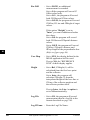
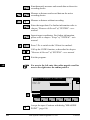
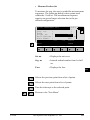
IN
General notes
Units in this manual
Specifications within this manual always apply to the
following units:
EL
Units of length:
- in m (meters)
- in addition, within brackets in ft (feet)
GN
Units of angle:
- in ° ' "
- in addition, within brackets in gon
Units of temperature:
- in °C
- in addition, within brackets in °F
Preparation
All program sequences are based on a unified structure.
The clearly-designed display with the function keys
makes learning easy. Each program has a configuration
dialog. In this dialog, the user can match programspecific parameters to changes in requirements and
sequences. The various possibilities are described in the
instructions for the individual programs.
Settings
To avoid temporarily-stored information being lost
when the TPS1000 automatically switches off after long
periods of disuse, you should set the "sleep mode"
instead of the automatic switchoff. For more
information, please refer to section "Fixed keys"
("Power off, Sleep") of "System" - user manual.
Each application takes over the settings (units,
recording format, display format etc.) allocated to the
appropriate user.
© Leica
TPS-System 1000 Programs-2.3.1en
23
If required, these user settings must be defined in
advance. For more information, please refer to section
"User configuration" of "System" - user manual.
EL
Data exchange
GN
If the settings in an application are altered, these
changed values will be taken over in the other
applications also and in „Measure and record“. The
settings affected are the station coordinates and the
circle orientation, along with parameters such as the
reflector constant, reflector height, and data for distance
reduction. This data can be altered in every application.
The measurement data is stored in the file selected.
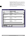
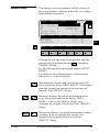
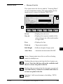
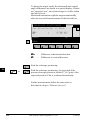
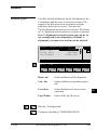
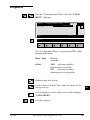
Using the program
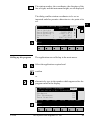
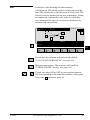
Instrument field setup
The setup is called up in the main menu.
To start with, the user profile and the file for storing
measurement data can be selected in the start-up
display.
SETUP\ START-UP DISPLAY
Select user
User templ.
Rec. device
Meas. file
Data file
14:03
template & files
: Polar(Standard)
:
Memory Card
: 1 √ FILE01.GSI
: 2 √ FILE02.GSI
QSET
STN
LIST
HELP
F1
24
F2
F3
TPS-System 1000 Programs-2.3.1en
F4
F5
F6
© Leica
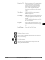
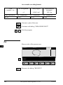
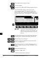
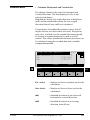
The station number, the coordinates, the direction of the
line of sight, and the instrument height, are all displayed
The dialog enables station coordinates to be set or
imported and also permits a direction to a tie point to be
EL
set.
GN
14:03
STATION 12
1.634 m
1010.567 m
-34213.077 m
345.655 m
390°35'58"
STATION DATA
Station no. :
Inst.Height :
Stat.Easting:
Stat.Northg :
Stat.Elev. :
Hz
:
REC
Hz0
MC
SETUP\
IMPOR αNUM
HELP
F1
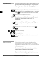
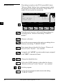
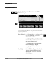
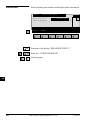
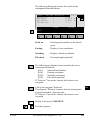
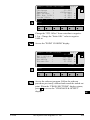
Calling up the program
F2
F4
F3
F5
F6
The applications are called up in the main menu.
Select the application required and
confirm
or
...
alternatively type in the number which appears after the
program name in the display.
14:03
MAIN MENU: PROGRAMS
Orientation & Ht. Transfer 00
Resection
01
Stakeout
02
Tie Distance
03
Free Station
04
EXTRA
CAL
CONF
DATA
SETUP MEAS
HELP
F1
© Leica
F2
F3
TPS-System 1000 Programs-2.3.1en
F4
F5
F6
25
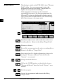
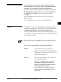
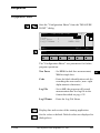
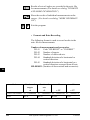
Designation of keys
EL
The effects of the fixed keys and of a few function keys are
the same as their effects in "MEASURE AND RECORD".
These keys are generally omitted from the descriptions
of the applications and from the ON-LINE help.
Continues sequence after input, measurements etc. have
been concluded. If the measurement dialog is concluded
with
the measurement data will not be recorded.
GN
Erases incorrect alphanumeric input.
"REC" Records in a pre-established format manually-entered
coordinates, measurements or the results of
calculations.
Quits current dialog and calls up previous dialog.
Changes and inputs to dialog are rejected and are not
stored.
Displays the second level of the function keys
.
-
Calls ON-LINE help.
Closes application.
Calls up code input or code function in measurement
dialog.
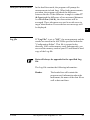
Target eccentricity
If the reflector cannot be set up directly over the
desired point, or if the point cannot be seen from the
instrument, the function 'OFFS' may be used to make an
offset measurement.
Previous to the input of the values for eccentricity, a
distance must be measured to the reflector.
For more information, please refer to section
'Measurement & recording' of 'System'-user manual.
26
TPS-System 1000 Programs-2.3.1en
© Leica
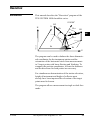
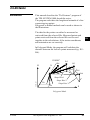
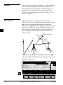
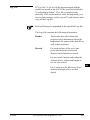
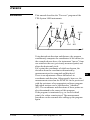
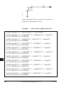
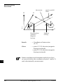
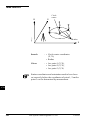
Orientation and Height Transfer
Introduction
This manual describes the "Orientation and Height
Transfer" program of the TPS SYSTEM 1000
theodolite series.
0°00'00"
H
OH
N
Hz
E
PROG_Z01
∆H
E0
H0
H
N
N0
E
The instrument must be set up on a known point. The
program "ORIENTATION" calculates an angular
correction for the instruments horizontal circle, so that
0.0000 of the horizontal circle corresponds with grid
north (Orientation correction), using reference points
with known Easting and Northing.
For simultaneous determination of the station elevation,
height of instrument and height of reflector must
already have been input and the elevation of the target
points must be known.
The program handles a maximum of 10 points.
© Leica
TPS-System 1000 Programs-2.3.1en
27
Enter the target point number and height of the reflector
.
ORINT\
14:03
TARGET POINT
Point no.
:
Refl.Height :
OH
CALC
LIST
HELP
CONF
F1
F2
MC
Target Point
12
1.300
<--
m
-->
F3
Run the calculation. Note, the
after the first measurement.
F4
F5
F6
key will be assigned
Entry of target points into a list as well as selecting
points for further use.
Displays the previous point from the list of points
entered. Note that this key will not be available until
there is at least one point in the list.
Displays the next point in the list of points entered.
Note that this key will not be available until there is at
least one point in the list.
Retrieve the coordinates of the target point from the
selected file. For further information, please refer to
dialog "IMPORT" described in the "System" - user
manual.
Start the "CONFIGURATION"
28
TPS-System 1000 Programs-2.3.1en
© Leica
Enter a maximum of 10 points. The same point can be
retrieved several times.
14:03
1
2
3
4
5
6
ORINT\ POINT LIST
Point
Point
Point
Point
Point
Point
1
2
3
4
5
6
:
:
:
:
:
:
Point 7
Point 8
Point 9
Point10
:
:
:
:
MC
Point List
OH
7
8
9
0
HELP
F1
F2
F3
F4
F5
F6
Return to the dialog "Target Point".
© Leica
TPS-System 1000 Programs-2.3.1en
29
Measure Mode
This dialog is similar to the TPS 1000’s basic "Measure
Mode" dialog. Once a measurement is taken, the
program will return to the dialog "Target Point" to
acquire the next point for measuring.
If the orientation correction can be calculated
successfully from any of the first measurements, the
∆Hz and ∆V values are displayed for further entered
target point. Motorized theodolites will automatically
drive the telescope to the target point.
OH
ORINT\ MEASURE MODE (GSI)14:03
ALL
:
:
:
:
:
:
DIST
1
216°55'50"
71°16'20"
1.300
385.231
-----
REC
HELP
F1
MC
Point no.
Hz
V
Refl.Height
Slope Dist.
∆Hz
m
m
TARGT
I<>II
F2
F3
F4
F5
F6
Simultaneously measure and record data on the active
recording device. Return to the dialog "Target Point".
Measure a distance.
Record the measurement on the active recording device.
Return to the dialog "Target Point".
Enter target data. For further information, please refer
to chapter "Measure & Record" described in the
"System" - user manual.
Change the theodolite face.
Call up the CODE function, as described in chapter
"Measure & Record" described in the "System" - user
manual.
Exit the program.
Accept the measurement and return to the dialog
"Target Point".
30
TPS-System 1000 Programs-2.3.1en
© Leica
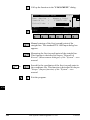
Calculation
Calculates the orientation, the elevation and the
respective standard deviations.
14:03
10
5
1.635 m
2134.234 m
4723.365 m
521.643 m
Station no. :
No. of Pts. :
Inst.Height :
Easting
:
Northing
:
Elevation
:
S.ORI S.HT
STORE PLOT
Orientation :
σElevation :
σOrient
:
HELP
MC
ORINT\ RESULTS <ROBUST>
MORE
2°12'34"
0.010
0°00'03"
OH
m
LSQRS
F1
F2
F3
F4
F5
F6
Station no
: Point number assigned to the station
No. of Pts
: Number of points measured
Inst.Height
: Instrument Height
Easting
: Easting of the station entered.
Northing
: Northing of the station entered.
Elevation
: Calculated elevation of the station
Orientation
: Oriented direction
σ Elevation
: Standard deviation of the Elevation
σ Orient
: Standard deviation of the Orientation
Set orientation on the instrument. Note that once this
key has been pressed it will not be possible to
execute more measurements.
Set station elevation on the instrument. Note that once
this key has been pressed it will not be possible to
execute more measurements.
© Leica
TPS-System 1000 Programs-2.3.1en
31
Record the following results into the active file:
WI 11
WI 25
WI 84
WI 85
WI 86
WI 87
WI 88
OH
Station Point Number
Orientation correction
Station Easting
Station Northing
Station Elevation
Last reflector height used
Instrument Height
Sketch of the station and the reference points used.
Show the results of individual measurements on the
screen (see dialog "More Information").
Measure more points. The program will recall the
"TARGET POINT" dialog.
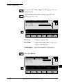
Select between the "Robust" method and the "Variation" method.
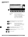
More Information
Display the residuals of individual measurements. You
can also disable points from the calculation of
orientation or height as well as delete erroneous
measured points.
14:03
2/10
Use for HT. : YES Status: ON
Point no.
:
Point01
Error flag :
NONE
∆ Hz
:
0°00'03"
∆ Distance :
0.050 m
RECLC
<--
∆ Height
Refl.Height
Easting
Northing
Elevation
-->
MEAS
:
:
:
:
:
DEL
0.020
1.555
991.427
1995.162
402.466
MC
ORINT\ MORE INFORMATION
NO
m
m
m
m
m
HELP
F1
32
F2
F3
TPS-System 1000 Programs-2.3.1en
F4
F5
F6
© Leica
2/10
: Sequence number of the current point
and total number of points in the
measurement set. The scroll bar shows
the sequential position of the
measurements, graphically.
Use for Ht.
: Use this measurement for height
determination (YES/NO)
Status
: Use this measurement for calculation
(ON/OFF).
Point no
: The target point number.
Error Flag
: Identified erroneous measurements.
Possible values are:
NONE
measurement is OK
HZ
horizontal angle error
DIST
distance error
HT
height difference error
The flags may also be combined, i.e.
DIST + HZ
∆ Hz.
: Difference between calculated and
measured horizontal angle
∆ Distance
: Difference between calculated and
measured distance
∆ Height
: Difference between calculated and
measured height
Refl. Ht.
: Reflector height used for the target
point
OH
Easting, Northing, Elevation: Target coordinates used.
Recalculate the result.
Scroll to the measurements of the previous point.
Scroll to the measurements of the following point.
Measure more points. Return to the dialog "Target
Point".
Delete a point from the set of measurements. You can
now measure a new point in its place.
Exit the program.
© Leica
TPS-System 1000 Programs-2.3.1en
33
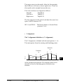
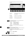
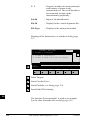
Plot
Generates a plot showing the measurement
configuration.
The station point is in the center and the top of the
sketch shows the direction of grid north. The sketch is
true in angular but not true in distances.
Points are numbered sequentially in the order in witch
they were measured.
Points not used in the calculation are marked with a
dotted line.
OH
14:03
PLOT
2
MC
ORINT\
1
3
5
4
RECLC
MEAS
HELP
F1
F2
F3
F4
F5
F6
Recalculate the result and return to the dialog
"CALCULATION RESULTS".
Measure more points. The program will recall the
"TARGET POINT" dialog.
...
Toggle any point ON or OFF by pressing the numeric
key corresponding to the sequence number of the point.
Note, that
represents point 10
Exit the program.
34
TPS-System 1000 Programs-2.3.1en
© Leica
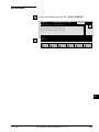
Configuration
Configuration Editor
Start the "Configuration Editor" from the "TARGETPOINT" dialog.
OH
14:03
0°00'32"
0.0250 m
0.0250 m
NO
NO
OFF
CONFIGURATION
Hz Ori Acc :
Ht Acc TP
:
Posn Acc TP :
Two faces
:
User Displ :
Log File
:
INFO
DFLT
Log FlName :
MC
ORINT\
EDIT
ORIENT.LOG
HELP
F1
F2
F3
F4
F5
F6
The "Configuration Editor "sets parameters for further
program operations:
© Leica
Hz Ori Acc
: Limit for the standard deviation of the
orientation. The orientation is
regarded as "error free", if the
computed standard deviation of the
orientation is within twice the entered
value.
Ht Acc TP
: Height accuracy of the target points.
The entered value, is used as an "a
priori" accuracy in the calculation.
The height is regarded as "error free",
if the computed standard deviation is
within twice the entered value.
TPS-System 1000 Programs-2.3.1en
35
Posn Acc TP : Position accuracy of the target points.
The entered value, is used as an "a
priori" accuracy in the calculation.
The position is regarded as "error
free", if the computed standard
deviation is within twice the entered
value.
Two Faces
: YES for dual-face measurement,
NO for single-face.
User Disp
: YES; the measured value indication is
used from application "Measure and
record".
NO; the default indication is used for
"Orientation and Height Transfer".
Log File
: ON, records measurements in a LogFile.The format is described on page
37.
OH
Log FlName : Enter the Log File Name.
Displays date and version.
Set the values to default. Default values are shown in
dialog on page 35.
Exit the program.
Store the current configuration and proceed to the
dialog "TARGET POINT".
36
TPS-System 1000 Programs-2.3.1en
© Leica
Dual-face Measurement
In the dual-face mode, the program will prompt for
measurements in both faces. When both measurements
are taken, the program will check the difference
between the two. If the difference in angle is within 27'
(0.5 gon) and the difference of two measured distances
is within 0.5 m (1.64 ft), the observations will be
averaged. These tolerances are used to avoid errors in
target identification. If exceeded an error message will
be displayed.
OH
Log file
If "Log File" is set to "ON" the measurements and the
results are stored in the ASCII-file specified within the
"Configuration Editor". This file is created in the
directory LOG on the memory card. Subsequently, you
can read the memory card on your PC and obtain a hard
copy of the Log-file.
Data will always be appended to the specified Logfile.
The Log-file contains the following information:
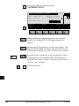
Header
© Leica
The header line will contain the
program used, information about the
instrument, the name of the data file as
well as date and time.
TPS-System 1000 Programs-2.3.1en
37
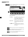
Record
For each measurement, a record will be
stored containing :
• Station coordinates
• station height,
• orientation correction
• standard deviations for
height and
orientation correction
The residuals for:
• horizontal angles,
• heights and
• measured distances
are also listed.
OH
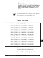
Leica VIP Orientation + Ht. Transfer V 2.10
Instrument
: TCM1100, Serial 412160, (not named)
User templ.
: User 1
Meas. file
: FILE12.GSI
Program Start
: 09/04/1996 at 12:57
Station no.
: 2000
E= -0.0006m N= -0.0002m ELV= 398.3961m hi= 1.6000m
Using Robust Solution
Station Elev.
Ori.Corr.
S.Dev. Elev.
S.Dev. Orient.
:
:
:
:
398.3929m
40'36"
0.0035m
0°00'04"
3 point(s) measured :
##
1
2
3
Point no.
500
501
502
∆ Hz
-0°00'55"
-0°00'48"
0°00'52"
∆ Height
0.0026m
0.0044m
-0.0070m
∆ Distance
0.0020m
0.0016m
-0.0000m
Error Flag
NONE
NONE
NONE
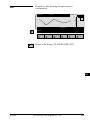
Typical log file entry in the "Orientation and Height Transfer" program
38
TPS-System 1000 Programs-2.3.1en
© Leica
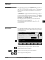
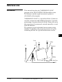
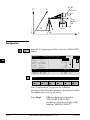
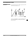
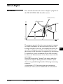
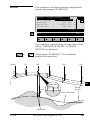
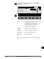
Resection
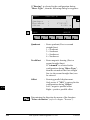
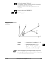
Introduction
This manual describes the "Resection" program of the
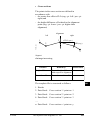
TPS SYSTEM 1000 theodolite series.
IV
EL
0°00'00"
Pt2
H
N
AH
D2
Hz1
Pt1
RE
D1
PROG_Z02
Hz2
E0
H0
N0
E
The program can be used to deduce the three-dimensional coordinates for the instrument station and the
orientation of the horizontal circle from measurements
to 2 target points with know Easting and Northing. To
compute the position coordinates, at least the distances
and the directions for both points are necessary.
For simultaneous determination of the station elevation,
height of instrument and height of reflector must
already have been input and the elevation of the target
points must be known.
The program allows measurement in single or dual-face
mode.
© Leica
TPS-System 1000 Programs-2.3.1en
OH
39
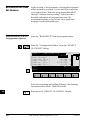
Enter station point number and height of the instrument.
IV
RESEC\
EL
Station no.
Inst.Height
14:03
STATION DATA
:
:
MC
Station Data
1
1.555
m
AH
αNUM
OH
HELP
RE
F1
CONF
F2
F3
F4
F5
F6
Proceed to the dialog "Target PoinT"
Start the "Configuration"
40
TPS-System 1000 Programs-2.3.1en
© Leica
Enter the target point number and height of the
reflector.
RESEC\
Point no. :
Refl.Height :
IV
14:03
TARGET POINT
MC
Target Point
30
1.300
m
EL
AH
IMPOR αNUM
OH
HELP
RE
F1
F2
F3
F4
F5
F6
Retrieve the coordinates of the point entered from the
active file. For further information, please refer to
dialog "Import" described in the "System" - user
manual.
© Leica
TPS-System 1000 Programs-2.3.1en
41
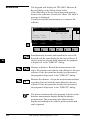
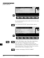
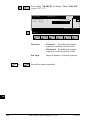
Measure Mode
IV
This dialog is similar to the TPS System1000’s basic
"Measure Mode" dialog. Once a measurement is taken,
the program will return to the dialog "Target Point" to
acquire the next point for measuring.
RESEC\ MEASURE MOD (GSI) 14:03
AH
OH
RE
Point no.
Hz
V
Refl.Height
Slope Dist.
:
:
:
:
:
ALL
REC
DIST
1
286°55'50"
91°16'20"
0.000
-----
HELP
F1
MC
EL
I
m
m
αNUM
TARGT
I<>II
F2
F3
F4
F5
F6
Simultaneously measure and record data on the active
recording device. Return to the dialog "TARGET
POINT".
Measure a distance.
Record the measurement on the active recording device.
Return to the dialog "TARGET POINT".
Enter target data as described in chapter "Measure &
Record" of the "System" - user manual.
Assigned with "aNUM" at point number input; assigned
with "EDIT" at numerical input.
Change the theodolite face.
Call up the CODE function, as described in chapter
"Measure & Record" of the "System" - user manual.
Exit the program.
Accept the measurement and return to the dialog
"TARGET POINT".
42
TPS-System 1000 Programs-2.3.1en
© Leica
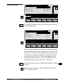
Calculation
In this dialog the calculated station coordinates are
shown with the orientation.
RESEC\CALCULATION RESULTS 14:03
1
2
1.635
2134.234
4231.365
580.643
SET
STORE
Orientation
σEasting
σNorthing
σElevation
σOrient
:
:
:
:
:
IV
MC
Station no. :
No. of Pts. :
Inst.Height :
Easting
:
Northing
:
Elevation
:
EL
m
m
m
m
AH
OH
2°12'34"
0.003
0.005
0.005
0°00'03"
m
m
m
RE
HELP
F1
© Leica
F2
F3
F4
F5
F6
Station no
: Station point number
No. of Pts
: Number of points measured
Inst.Height
: Instrument Height
Easting
: Calculated Easting (Y) for the station.
Northing
: Calculated Northing (X) for the station.
Elevation
: Calculated elevation for the station
Orientation
: Oriented direction
σ Easting
: Standard deviation of Easting
σ Northing
: Standard deviation of Northing
σ Elevation
: Standard deviation of the Elevation
σ Orient
: Standard deviation of the Orientation
TPS-System 1000 Programs-2.3.1en
43
Set orientation and station coordinates on the
instrument. Note that this key will end the program.
Record the following results on the active recording
device:
IV
EL
WI 11
WI 25
WI 84
WI 85
WI 86
WI 87
WI 88
AH
OH
RE
Station Point Number
Orientation correction
Station Easting
Station Northing
Station Elevation
Last rflector height used
Instrument Height
Exit the program.
44
TPS-System 1000 Programs-2.3.1en
© Leica
Configuration
IV
Configuration Editor
EL
Start the "Configuration Editor" from the "STATION
DATA" dialog.
AH
OH
14:03
0°00'32"
0.025 m
0.025 m
NO
NO
OFF
CONFIGURATION
Hz Ori Acc :
Ht Acc TP
:
Posn Acc TP :
Two Faces
:
User Displ :
Log File
:
INFO
DFLT
Log FlName
:
MC
RESEC\
EDIT
RESECT.LOG
HELP
F1
F2
F3
F4
F5
F6
The "Configuration Editor" sets parameters for further
program operations:
© Leica
Hz Ori Acc
: Limit for the standard deviation of the
orientation. The orientation is
regarded as "error free", if the
computed standard deviation of the
orientation is within twice the entered
value.
Ht Acc TP
: Height accuracy of the target points.
The entered value, is used as an "a
priori" accuracy in the calculation.
The height is regarded as "error free",
if the computed standard deviation is
within twice the entered value.
TPS-System 1000 Programs-2.3.1en
45
RE
EL
Posn Acc TP : Position accuracy of the target points.
The entered value, is used as an "a
priori" accuracy in the calculation.
The position is regarded as "error
free", if the computed standard
deviation is within twice the entered
value.
AH
Two Faces
IV
: YES for dual-face measurement,
NO for single-face.
OH
Ben.Anzeige : YES; the measured value indication is
used from application "Measure and
record".
NO; the default indication is used for
the "Resection".
RE
Log File
: Set to ON, the program will record
measurement data in a log file as
described on page 47.
Log FlName : Enter the Log File Name.
Displays date and version.
Set the value to the default as described in dialog on
page 45.
Exit the program.
Store the current configuration and proceed to the
dialog "STATION DATA".
46
TPS-System 1000 Programs-2.3.1en
© Leica
Dual-face Measurement
In the dual-face mode, the program will prompt for
measurements in both faces. When both measurements
are taken, the program will check the difference
between the two. If the difference in angle is within 27'
(0.5 gon) and the difference of two measured distances
is within 0.5 m (1.64 ft), the observations will be
averaged.
These tolerances are used to avoid errors in target
identification.
If exceeded an error message will be displayed.
IV
EL
AH
OH
RE
Log File
If "Log File" is set to "ON" the measurements and the
results are stored in the ASCII-file specified within the
"Configuration Editor". This file is created in the
directory LOG on the memory card. Subsequently, you
can read the memory card on your PC and obtain a hard
copy of the Log-file.
Data will always be appended to the specified Log-file.
The Log-file contains the following information:
© Leica
Header
The header line will contain the
program used, information about the
instrument, the name of the data file as
well as date and time.
Record
For each measurement, a record will
be stored containing :
Station coordinates and orientation
correction, standard deviation for
Easting, Northing, Height of station
and orientation correction.
The residuals for horizontal angles,
heights and measured distances are
also listed.
TPS-System 1000 Programs-2.3.1en
47
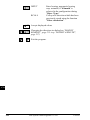
Leica VIP Resection V 2.10
Instrument
: TCM1100, Serial 412160, (not named)
User templ.
: User 1
Meas. file
: FILE12.GSI
Program Start
: 09/04/1996 at 12:52
IV
EL
Using Least-Squares Solution
AH
OH
RE
Station no.
: 2000
E= -0.0011m N= -0.0006m ELV= 398.3951m hi= 1.6000m
Ori.Corr.
S.Dev. East
S.Dev. North
S.Dev. Elev.
S.Dev. Orient.
;
:
:
:
:
240°50'51"
0.0003m
0.0003m
0.0047m
0°00'49"
2 point(s) measured :
## Point no.
1 500
2 501
∆ Hz
-0°00'55"
-0°00'18"
∆ Height
0.0047m
-0.0047m
∆ Distance
0.0001m
0.0002m
Error Flag
NONE
NONE
Typical log file entry in the "Resection" program
48
TPS-System 1000 Programs-2.3.1en
© Leica
Tie Distance
Introduction
IV
This manual describes the "Tie Distance" program of
the TPS SYSTEM 1000 theodolite series.
The program calculates the length and azimuth of a line EL
connecting two points.
AH
Polygonal or Radial methods can be used as shown in
the illustrations.
OH
The data for the points can either be measured or
retrieved from the selected file. Measured points and
points retrieved from the selected file can be used
together in the calculations, if the station coordinates
and orientation are set correctly.
BS
TD
In Polygonal Mode, the program will calculate the
distance between the last two points measured (eg. Pt3 Pt4).
0°00'00"
N
H
Pt2
Pt3
Pt1
Hz2
Hz1
Hz3
Pt4
Slope Dist 1
PROG_Z03
Slope Dist 2
E0
Slope Dist 3
N0
E
Polygonal Mode
© Leica
TPS-System 1000 Programs-2.3.1en
49
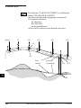
In Radial Mode, the program will calculate the distance
between the last point measured (called a Radial Point)
(Pt2, Pt3 ...) and a fixed Center Point (Pt1).
IV
0°00'00"
EL
Pt2
Pt1 0°00'00"
AH
H
OH
N
Pt3
Hz3
Hz2
Hz1
Pt4
BS
TD
Slope Dist 1
PROG_Z04
Slope Dist 2
E0
N0
Slope Dist 3
E
Radial Mode
Toggling between Polygonal and Radial Mode at any
time while working is possible.
50
TPS-System 1000 Programs-2.3.1en
© Leica
Measure Mode
This dialog is used in accordance with the settings of
the system function "Measure & Record" or according
to the dialog shown below.
IV
ALL
F1
:
:
:
:
:
:
DIST
Easting
Northing
Elevation
HELP
14:03
546
1.654 m
230°45'23"
4°52'35"
----- m
----- m
FIRST POINT
Point no.
Refl.Height
Hz
V
Slope Dist.
Height diff
REC
-------------
F2
BS
m
m
m
TD
I<>II
F3
F4
F5
F6
The input for the start point is only possible after the
in the dialog
program start or with the function
"RADIAL MODE".
For all following points the program requests (NEXT
POINT).
The dialog for the following points is identical with
dialog above, except for the title.
Simultaneously measure and record in the active file.
Proceed with the dialog "NEXT POINT". If the second
point has already been measured, the program will
proceed to the "RESULT" dialog.
Measure a distance. Record the measurement in the
active file and proceed with the dialog "NEXT
POINT". If the second point has already been
measured, the program will proceed to the "RESULT"
dialog.
Measure the distance. Accept the measurement without
recording. If the second point has already been
measured, the program will proceed with the
"RESULT" dialog.
© Leica
TPS-System 1000 Programs-2.3.1en
AH
OH
TARGT IMPOR
:
:
:
CONF
EL
MC
TIED\
51
Enter the target data.
For further information refer to chapter "Measure &
Record" of "System" - user manual.
IV
Import target coordinates.
For further information, please refer to chapter "Setup"
of "System" - user manual.
EL
AH
Start the "Configuration Editor".
OH
Change the theodolite face.
BS
Call up the CODE function, as described in chapter
"Measure & Record" of "System" - user manual.
TD
Exit the program
52
TPS-System 1000 Programs-2.3.1en
© Leica
Results
This dialog shows the results computed from the last
two points, which can be measured or retrieved from
the active file. The same results are calculated for both
methods.
Using "Polygon Mode" the calculations are always
based on the last two points, where as the "Radial
Mode" always uses the first point as a reference point.
IV
EL
AH
OH
14:03
12
13
4.567 m
342°52'35"
2.543 m
4.946 m
RADIAL MODE
Center Pt. :
Radial Pt. :
Hori.Dist. :
Azimuth
:
∆ Height
:
Slope Dist. :
N.PKT N.ZEN STORE
∆Easting
∆Northing
:
:
MC
TIED\
TD
POLYG
22.432
50.083
m
m
HELP
F1
© Leica
F2
F3
F4
F5
F6
Center Pt.
: Point number of the center point
Radial Pt.
: Point number of the radial point
Hori.Dist
: Horizontal distance between the two
points
Azimuth
: Azimuth from point 1 to point 2
∆ Height
: Height difference between point 1 and
point 2 (H2 - H1).
Slope Dist
: Slope distance between the two points
TPS-System 1000 Programs-2.3.1en
BS
53
∆ Easting
: Difference in Easting between point 1
and point 2 (E2 - E1).
The grid coordinates are only valid for
oriented instruments set up on a
known point.
∆ Northing
: Difference Northing between point 1
and point 2 (N2 - N1).
Note, the grid coordinates are only
relevant for oriented instruments set
up on a known point.
IV
EL
AH
OH
BS
TD
Return to the dialog "NEXT POINT" and measure the
next point.
Delete previous inputs. Proceed with the dialog "FIRST
POINT" to enter a new reference point. This function is
available for "RADIAL MODE" only.
Record the following results in the active file:
WI 11
WI 25
WI 35
WI 37
WI 39
WI 79
Point number of point 2 or radial point
number
Azimuth from point1 to point 2
Horizontal distance
Height difference between point 1 and
point 2
Slope distance
Point number of point 1 or center point
number
Toggle between Radial/Polygon Mode.
54
TPS-System 1000 Programs-2.3.1en
© Leica
Configuration
IV
Configuration Editor
EL
Start the "Configuration Editor" from the "FIRST
POINT" dialog.
OH
14:03
NO
NO
OFF
TIEDIST.LOG
CONFIGURATION
Two Faces
User Disp.
Log File
Log FlName
:
:
:
:
INFO
DFLT
MC
TIED\
AH
TD
YES
HELP
F1
F2
F3
F4
F5
F6
The "Configuration Editor" sets parameters for further
program operations:
Two Faces
: Set YES for dual-face measurement,
NO for single-face.
User Disp.
: YES to use the measurement display
set in the application "Measure &
Record".
Set NO to use the "Tie Distance"
default display.
Log File
: Set to ON, the program will record
measurement data in the Log File
according to the format described on
page 57.
Log FlName : Enter the Log File Name.
© Leica
TPS-System 1000 Programs-2.3.1en
BS
55
Displays date and version of the running application.
Set the values to default. Default values are displayed in
dialog on page 55.
IV
Exit the program.
EL
Store the current configuration and proceed to the
dialog "MEASURE MODE".
AH
OH
BS
TD Dual-face Measurement
56
In the dual-face mode, the program will prompt for
measurements in both faces. When both measurements
are taken, the program will check the difference
between the two. If the difference in angle is within 27'
(0.5 gon)) and the difference of two measured distances
is within 0.5 m (1.64 ft), the observations will be
averaged. These tolerances are used to avoid errors in
target identification. If exceeded an error message will
be displayed.
TPS-System 1000 Programs-2.3.1en
© Leica
Log File
If "Log File" is set to ON the measurements and the
results are stored in the ASCII-file specified within the
"Configuration Editor". This file is created in the
directory LOG on the memory card. Subsequently, you IV
can read the memory card on your PC and obtain a hard
copy of the Log-file.
EL
AH
Data will always be appended to the specified Log-file.
BS
The Log-file contains the following information:
© Leica
Header
The header line will contain the
program used, information about the
instrument, the name of the data file as
well as date and time.
Record
For each measurement, a record will
be stored containing :
Point No 1, Point No. 2, Hori. Dist.,
Azimuth, ∆Height, Slope Dist.
TPS-System 1000 Programs-2.3.1en
OH
57
TD
Leica VIP Tie Distance V 2.10
Instrument
: TCM1100, Serial 412160, (not named)
User Templ.
: User 1
Meas. File
: FILE12.GSI
Program Start
: 09/04/1996 at 01:13
IV
EL
Station no.
:
1151
E= 0.0000m N= 0.0000m ELV= 400.0000m hi= 0.0000m
Point No.1
:
1020
E= -31.2368m N= -0.2083m ELV= 400.0626m
Point No.2
:
1030
E= -30.5679m N= -17.8404m ELV= 403.1198m
Point no.1
Point no.2
Hori.Dist.
Azimuth
: 1020
: 1030
: 17.6448m
: 197°58'40"
∆Height
Slope dist.
: 3.0572m
: 17.9077m
Point No.2
:
AH
OH
BS
TD
1040
E= -57.7040m N= -0.4265m
Point No. 1
Point No.2
Hori.Dist.
Azimuth
: 1030
: 1040
: 32.2430m
: 336°32'14"
∆Height
Slope dist.
:
:
H= 400.1028m
-3.0170m
32.3839m
Typical log file entry in the "Tie Distance" program
(Polygonal Mode)
58
TPS-System 1000 Programs-2.3.1en
© Leica
Stakeout
Introduction
This manual describes the "STAKEOUT" program of IV
the TPS SYSTEM 1000 theodolite series. The program
EL
allows points with known coordinates to be placed in
the field.
AH
"STAKEOUT" requires the instrument to be set up on
a known point with the instrument oriented. The station
point can be determined also with the programs "FREE
STATION" and "RESECTION".
The stakeout points can either be retrieved from the
selected file or entered manually.
The program permits selection of either 2D or 3D
stakeout modes.
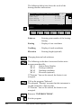
Search Point
The "SEARCH POINT" dialog informs about the active
recording device, the active file for data storage and the
present point/code.
14:03
SEARCH POINT
Define stakeout point
Rec. device :
Memory Card
Search in
:
FILE01.GSI
Pkt/Code
:
4
SEARC αNUM
INPUT
HELP
F1
MC
STAKE\
CONF
F2
F3
F4
F5
F6
Manually enter the stakeout point. The TPS 1000
manual input dialog will appear.
or
Initiate a search of the point in the database.
Allows program configuration.
© Leica
TPS-System 1000 Programs-2.3.1en
59
OH
BS
SM
SO
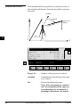
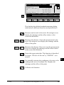
Coarse Positioning
IV
EL
AH
Once the coordinates of the stakeout point have been
acquired, the program proceeds to "Coarse
Positioning". This option is available to direct the prism
from the previous point placed to the next.
The "Coarse Positioning" calculates various
displacements, depending on the method selected.
Displacements are computed between the last point
placed and the actual stakeout point selected. For more
information refer to chapter "Stakeout".
OH
BS
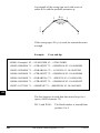
SM Line Offset
SO
The stakeout values of each point are computed in
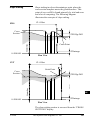
relation to the base formed by the last two points.
If the elevation is known for the point to be staked out,
the height difference in relation to the last base point
(Pt2), is displayed. In particular, this method is
advantageous for long objects (traffic routes). Values
for positioning are only displayed after two stakeout
points.
Pt1
H
Pt2
N
Line
Pt3
PROG_Z05
Offset
∆Height
E0
N0
E
Pt3 ... point to be staked
60
TPS-System 1000 Programs-2.3.1en
© Leica
14:03
CURB
90°10'02"
98°34'45"
4.105 m
1.250 m
0.340 m
LINE OFFSET
Target no.
Azimuth
Hz
Line
Offset
∆Height
:
:
:
:
:
:
MC
STAKE\
IV
STAKE
HELP
METHD
EL
PLOT
AH
F1
F2
F3
F4
F5
F6
OH
or
BS
Target no
: Number of the point to be staked.
Azimuth
: Azimuth from the station to the point
to be staked.
Hz
: Present theodolite direction. Note, if
the instrument is oriented and the
azimuth and Hz angle are
corresponding, the instrument is
pointing to the point to be staked.
Line
: Distance along the line defined by the
last two points staked
Offset
: Orthogonal offset from the defined
line
∆ Height
: Height difference from the last point
staked.
Proceed to "STAKEOUT". Motorized theodolites can
drive the telescope to the horizontal and vertical
direction of the point to be placed.
Change stakeout method. For more information refer to
chapter "Select Stakeout Method".
Generate a plot of the stakeout data. For more
information to chapter "Plot".
Exit the program.
© Leica
TPS-System 1000 Programs-2.3.1en
61
SM
SO
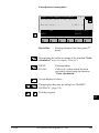
Orthogonal
IV
EL
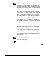
Setting out values are computed as orthogonal
coordinates to the baseline between instrument station
and prism. If the elevation is also known, ∆H is given in
relation to the last prism - point measured.
Note, data will be displayed if there is at least one point
measured.
Pt1
N
H
AH
OH
point to be staked
BS
+∆Q
SM
−∆L
∆H
E0
PROG_Z06
SO
N0
E
14:03
CURB
90°10'02"
98°34'45"
4.105 m
1.250 m
0.340 m
Target no.
Azimuth
Hz
∆L
∆Q
∆Height
:
:
:
:
:
:
MC
STAKE\ORTHOGONAL STAKE
STAKE
HELP
METHD
F1
62
F2
PLOT
F3
F4
F5
F6
Target no.
: Number of the point to be staked.
Azimuth
: Azimuth from the station to the point
to be staked.
TPS-System 1000 Programs-2.3.1en
© Leica
Hz Angle
: Present theodolite direction. Note, if
the instrument is oriented and the
azimuth and Hz angle are
corresponding, the instrument is
pointing to the point to be staked.
IV
∆ L and ∆ Q in relation to the baseline: EL
last stakeout point - instrument station.
∆L
∆Q
∆ Height
or
AH
: In-line distance ∆ L is positive for
points further than the last prism
position measured.
OH
BS
: Distance perpendicular to the
baseline. ∆ Q is positive for points on
the right of the baseline.
SO
: Height difference from the last point
measured.
Proceed to "STAKEOUT". Motorized theodolites can
drive the telescope to the horizontal and vertical
direction of the point to be placed.
Change stakeout method.
For more information refer to chapter "Select Stakeout
Method".
Generate a plot of the stakeout data.
For more information to chapter "Plot".
Exit the program.
© Leica
SM
TPS-System 1000 Programs-2.3.1en
63
Azimuth and Distance
This method defines the point to be staked in terms of
the azimuth and distance from the theodolite station to
the point.
0°00'00"
IV
EL
N
H
Azimuth
point to be
staked
AH
Slope
OH
Dist.
BS
SM
PROG_Z07
E0
SO
N0
E
STAKE\AZIMUTH & DISTANCE 14:03
:
:
:
:
:
:
CURB
90°10'02"
98°34'45"
4.105
4.021
0.340
MC
Target no.
Azimuth
Hz
Slope Dist.
Horiz.Dist.
∆Height
m
m
m
STAKE
HELP
METHD
F1
64
F2
PLOT
F3
F4
F5
F6
Target No.
: Number of the point to be staked.
Azimuth
: Azimuth from the station to the point
to be staked.
Hz
: Present theodolite direction.
Note, if the instrument is oriented
and the azimuth and Hz angle are
corresponding, the instrument is
pointing to the point to be staked.
TPS-System 1000 Programs-2.3.1en
© Leica
Slope Dist
: Slope distance from the instrument
station to the stakeout point.
Horiz. Dist
: Horizontal distance from the
instrument station to the stakeout
point.
∆ Height
IV
EL
: Height difference from the instrument
station to the stakeout point.
AH
OH
BS
or
Proceed to "STAKEOUT". Motorized theodolites can
drive the telescope to the horizontal and vertical
direction of the point to be placed.
Change stakeout method.
For more information refer to chapter "Select Stakeout
Method".
Generate a plot of the stakeout data. For more
information to chapter "Plot".
Exit the program.
© Leica
TPS-System 1000 Programs-2.3.1en
65
SM
SO
Stakeout
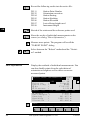
IV
EL
Points must have known coordinates. Various methods
can be used, depending on the Stakeout Method set.
Motorized instruments can drive the telescope to the
horizontal and vertical direction of the point to be
staked. For more information refer to chapter "Select
Stakeout Method".
AH
OH Polar Stakeout
BS
SM
SO
After the first distance has been measured, the
differences between calculated and measured direction
and between calculated and measured horizontal
distance are displayed. If the elevation of the point to be
staked is available, the height difference between the
last measured reflector and the point to be staked is
shown together with the measured elevation of the
reflector point.
point to be staked
∆Dist
N
H
∆Hz
Pt1
PROG_Z08
E0
∆H
N0
E
Values for ∆Hz and ∆D will be updated each time a new
distance is measured.
14:03
:
0025
:
90°10'02"
:
4.567 m
:FILL
0.102 m
:
32.543 m
Target no.
∆ Hz
∆ Dist
∆ Height
Elevation
ALL
DIST
HELP
METHD
F1
66
F2
REC
MC
STAKE\ POLAR STAKEOUT
TARGT POSIT
PLOT
F3
TPS-System 1000 Programs-2.3.1en
F4
F5
F6
© Leica
Target no.
: Point number of the point to be
staked.
∆ Hz
: Difference in Hz circle reading
between the actual horizontal
direction and the calculated direction.
∆ Dist
∆ Height
Elevation
IV
: Difference in horizontal distance
between the measured and calculated
distance.
EL
: Difference in height between the
measured reflector point and the
stakeout point, expressed both
numerically and as CUT/FILL.
OH
AH
BS
: Elevation of the measured target point.
SM
SO
Simultaneously measure and record data on the active
recording device.
Measure a distance.
Record the measurement on the active recording device.
Enter target data as described in chapter "Measure &
Record" of "System" - user manual.
Re-position the telescope on the target. Note, this
function is only available for motorized theodolites.
Change stakeout method. For more information refer to
chapter "Select Stakeout Method".
Generate a plot of the stakeout data. For more
information refer to chapter "Plot".
Exit the program.
Acquire the next point to stake.
© Leica
TPS-System 1000 Programs-2.3.1en
67
Orthogonal Stakeout
IV
EL
AH
Orthogonal offsets are computed using the baseline
between the last measured point and the instrument
station.
After the first distance measurement, the transverse and
longitudinal differences are displayed. If the elevation
of the stakeout point is available, the height difference
between the measured reflector and the point to be
staked is shown, and also the measured elevation of the
reflector point.
OH
point to be staked
∆Q
BS
∆D
N
H
SM
Pt1
SO
∆H
PROG_Z09
E0
N0
E
Values for ∆Q and ∆D will be updated each time a new
distance is measured.
14:03
CURB
0.012 m
4.567 m
0.102 m
32.543 m
Target no.
∆Q
∆D
∆ Height
Elevation
ALL
DIST
HELP
METHD
F1
68
F2
:
:
:
:FILL
:
REC
MC
STAKE\ORTHOGONAL STAKE
TARGT POSIT
PLOT
F3
F4
F5
F6
Target no.
: Point number of the point to be
staked.
∆Q
: Transversal displacement of the
reflector. Positive in sign if point is
right.
TPS-System 1000 Programs-2.3.1en
© Leica
∆D
: Longitudinal displacement of the
reflector. Positive in sign if stakeout
point is further away from station.
∆ Height
: Difference in height between
measured reflector point and the
stakeout point. Positive in sign if
stakeout point is higher than the
reflector position.
IV
: Elevation of the measured reflector
point.
OH
Elevation
EL
AH
BS
SM
SO
Simultaneously measure and record data on the active
recording device.
Measure a distance.
Record the measurement on the active recording device.
Enter target data as described in chapter "Measure &
Record" of "System" - user manual.
Re-position the telescope on the target. Note, this
function is only available for motorized theodolites.
Change stakeout method. For more information refer to
chapter "Select Stakeout Method".
Generate a plot of the stakeout data. For more
information refer to chapter "Plot".
Exit the program.
Acquire the next point to stake.
© Leica
TPS-System 1000 Programs-2.3.1en
69
Stakeout with auxiliary
points
IV
EL
AH
OH
BS
SM
The stakeout method computes values for points which
cannot be sighted directly.
Measure to the auxiliary point Pt1. The distance "Dist
1" and angle "Hz angle 1" to the stakeout point are
computed. Likewise proceed for auxiliary point Pt2.
The stakeout point can be set out using the 2 calculated
distances and/or angles from auxiliary points Pt1 and
Pt2.
The program automatically updates both distance and
angle values whenever a new point is measured. The
previous point Pt2 becomes Pt1 and the new point Pt
becomes Pt2.
Note, the auxiliary point to be measured will be marked
with an asterisk (*).
SO
Pt2
H
point to be
staked
N
Hz2
Dist2
Pt1
Dist1
Hz1
PROG_Z10
E0
N0
E
AUXILIARY POINTS 14:03
Target no.
Hz Angle 1
Dist 1
Hz Angle 2
Dist 2
∆Height
ALL
DIST
HELP
METHD
F1
Target no
70
F2
:
CURB
:*
90°01'02"
:*
4.567
:
150°22'34"
:
2.973
:CUT
-0.102
REC
MC
STAKE\
m
m
m
TARGT POSIT
PLOT
F3
F4
F5
F6
: Point number of the point to be
staked.
TPS-System 1000 Programs-2.3.1en
© Leica
Hz Angle 1
: Angle from the first auxiliary point to
the stakeout point.
Dist 1
: Distance from the first auxiliary point
to the stakeout point.
Hz Angle 2
: Angle from the second auxiliary point EL
to the stakeout point.
Dist 2
: Distance from the second auxiliary
point to the stakeout point.
∆ Height
AH
OH
: Difference in height between the last
measured reflector point and the
stakeout point. Positive in sign if
stakeout point is higher than the
reflector position.
Simultaneously measure and record data on the active
recording device.
Measure a distance.
Record the measurement on the active recording device.
Enter target data as described in chapter "Measure &
Record" of "System" - user manual.
Re-position the telescope on the target. Note, this
function is only available for motorized theodolites.
Change stakeout method. For more information refer to
chapter "Select Stakeout Method".
Generate a plot of the stakeout data. For more
information refer to chapter "Plot".
Exit the program.
Acquire the next point to stake.
© Leica
IV
TPS-System 1000 Programs-2.3.1en
71
BS
SM
SO
Stakeout from Coordinate
Differences
IV
EL
After the first distance measurement, the displacements
along the grid coordinate axes are displayed. If the
elevation of the point to be staked is available, the
height difference between the measured reflector and
the stakeout point is shown as well as the measured
elevation of the reflector point.
Pt1
AH
H
OH
N
BS
∆H
SM
SO
point to be
staked
∆Northing
PROG_Z11
E0
∆Easting
N0
E
Values for ∆E and ∆N will be updated each time a new
distance is measured.
14:03
Ta0025
0.101 m
0.567 m
-0.102 m
32.543 m
Target no.
∆ Easting
∆ Northing
∆ Height
Elevation
ALL
DIST
HELP
METHD
F1
72
F2
:
:
:
: CUT
:
REC
MC
STAKE\ GRID COORDINATES
TARGT POSIT
PLOT
F3
F4
F5
F6
Target no.
: Point number of the point to be
staked.
∆ Easting
: Displacement of the reflector along
the East-coordinate axis.
∆ Northing
: Displacement of the reflector along
the North-coordinate axis.
TPS-System 1000 Programs-2.3.1en
© Leica
∆ Height
Elevation
: Difference in height between the
measured reflector point and the
stakeout point. Positive in sign if
stakeout point is higher than the
reflector position.
IV
: Elevation of the measured reflector
point.
EL
AH
OH
Simultaneously measure and record data on the active
recording device.
Measure a distance.
Enter target data as described in chapter "Measure &
Record" of "System" - user manual.
Re-position the telescope on the target. Note, this
function is only available for motorized theodolites.
Change stakeout method. For more information refer to
chapter "Select Stakeout Method".
Generate a plot of the stakeout data. For more
information refer to chapter "Plot".
Exit the program.
Acquire the next point to stake.
TPS-System 1000 Programs-2.3.1en
SM
SO
Record the measurement on the active recording device.
© Leica
BS
73
Select Stakeout Method
IV
Select the stakeout method in any stakeout dialog.
STAKE\
AH
OH
BS
14:03
:
LINE OFFSET
: POLAR STAKEOUT
:
ON
:
2D
:
0.000 m
SELECT METHOD
Coarse Meth
Stakeout M.
3D Stakeout.
Position
Hght. Shift
POLAR ORTHO
AUX
GRID
MC
EL
LIST
HELP
SM
F1
SO
F2
F3
F4
F5
F6
Coarse Meth :
Select the method for "COARSE POSITIONING":
NONE
no static method used
LINE OFFSET
see chapter "Line Offset"
ORTHOGONAL
see chapter "Orthogonal"
AZIMUTH & DISTAN see chapter "Azimuth and
Distance"
Choosing NONE, the program will automatically
proceed to the selected "STAKEOUT METHOD" and
bypass the "COARSE POSITIONING" method after
you selected a new stakeout point.
Stakeout M. :
Select the method for "STAKEOUT":
POLAR STAKEOUT
see chapter "Polar
Stakeout"
ORTHOGONAL STAKE see chapter "Orthogonal
Stakeout"
AUXILIARY POINTS
see chapter "Stakeout with
auxiliary points"
GRID COORDINATES see chapter "Stakeout from
Coordinate Differences"
74
TPS-System 1000 Programs-2.3.1en
© Leica
3D Stakeout : ON for 3D stakeout,
OFF for 2D stakeout.
Position
: Select positioning method. (Motorized
instruments only):
IV
Off Automatic positioning off
2D
Positioning of the horizontal
EL
drive
AH
3D
Positioning vertical and
horizontal drive
Hght. Shift
: All heights are changed by this
amount. The value can be changed
only when you are in this dialog.
OH
BS
SM
SO
Plot
A plot is generated of the stakeout situation with a list
of the numeric values, corresponding to the
"STAKEOUT METHOD".
Note, below a typical plot is shown using the coordinate
"STAKEOUT METHOD".
∆E
R
14:03
PLOT
PS
∆N
∆E :
∆N :
0.024 m
0.012 m
MC
STAKE\
HELP
F1
© Leica
F2
F3
TPS-System 1000 Programs-2.3.1en
F4
F5
F6
75
Configuration
Start the "Configuration Editor" from the "SEARCH
POINT" dialog.
EL
STAKE\
14:03
ON
OFF
STAKEOUT.LOG
CONFIGURATION
3D Stake
:
Log File
:
Log FlName :
AH
MC
IV
OH
BS
INFO
SM
HELP
F1
SO
DFLT
F2
F3
F4
F5
OFF
F6
The "Configuration Editor" sets parameters for further
program operations:
3D Stake
: ON
for 3-dimensional stakeout.
Note the program will not perform 3D
stakeout if no elevation is available
for the point to be staked.
OFF
for 2-dimensional stakeout.
Note that there will be no difference in
height displayed.
Log File
: OFF
no recording in a Log file
SHORT reduce recording in a Log
file
LONG detailed recording in a Log
file
Display software-version
Set the value to default. (3D stake = ON) .
76
TPS-System 1000 Programs-2.3.1en
© Leica
Exit the program.
Store the current configuration and proceed to the
dialog "SEARCH POINT".
IV
EL
Log File
If "Log File" is set to "ON" the measurements and the
results are stored in the ASCII-file specified within the AH
"Configuration Editor". This file is created in the
OH
directory LOG on the memory card. Subsequently, you
can read the memory card on your PC and obtain a hard BS
copy of the Log-file.
SM
Data will always be appended to the specified Log-file. SO
The Log-file contains the following information:
Header
The header line will contain the
program used, information about the
instrument, the name of the data file as
well as date and time.
Record
SHORT
recording of design
coordinates, setout height and height
difference in the log file.
LONG
recording of design
coordinates, setout coordinates und
differences of coordinates in the log
file.
© Leica
TPS-System 1000 Programs-2.3.1en
77
Leica VIP Stakeout V 2.10
Instrument
: TCM1100, Serial 412160, (not named)
User templ.
: User 1
Meas. file
: FILE12.GSI
Program Start
: 09/04/1996 at 01:18
IV
EL
Station no.
:
AH
Point no.
Design
Staked
Deltas
OH
BS
:
:
:
:
3000
E= 21.016m
N= 64.666m
1152, Hght. Shift = 0.000m
E= 21.602m N= 62.184m
E= 21.606m N= 62.166m
dO= -0.004m dN= 0.018m
ELV= 420.467m hi= 1.700m
ELV= 420.115m
ELV= 420.355m hr= 1.500m
dELV= -0.240m
SM
Typical log file entry in the "STAKEOUT" program
SO
78
TPS-System 1000 Programs-2.3.1en
© Leica
Free Station
Introduction
This manual describes the "FREE STATION" program
of the TPS SYSTEM 1000 theodolite series.
IV
EL
AH
Pt1
Pt2
OH
N
H
BS
SM
Pt3
AS
PROG_Z19
FS
E0
N0
E
This program can be used to deduce the three-dimensional coordinates for the instrument station and the
horizontal orientation of the from measurements to a
maximum of 10 target points.
For simultaneous determination of the station elevation,
height of instrument and height of reflector must
already have been input and the elevation of the target
points must be known.
The program allows measurement in single or dual-face
mode.
Directions to target points can be determined, as can
any combination of direction and distance. To compute
the position coordinates, at least three elements (2
directions and 1 distance) are necessary.
© Leica
TPS-System 1000 Programs-2.3.1en
79
Enter station point number and height of the instrument.
IV
FREST\ STATION DATA
EL
Station no. :
Inst.Height :
14:03
MC
Station Data
1
1.555
m
AH
αNUM
OH
HELP
BS
F1
CONF
F2
F4
F3
F5
F6
SM
AS
Proceed to define the target points.
FS
Start the "CONFIGURATION"
Alpha-numerical/numerical input.
Enter the target point number and height of the
reflector.
FREST\
14:03
TARGET POINT
Station no. :
Refl.Height:
CALC
LIST
MC
Target Point
1
1.555
<--
m
αNUM
-->
HELP
F1
F2
F3
F4
F5
F6
Run the calculation. Note, the
key will be
assigned after sufficient measurements were taken to
calculate a position.
80
TPS-System 1000 Programs-2.3.1en
© Leica
Entry of target points into a list as well as selecting
points for further use.
Displays the previous point from the list of points you
entered. Note that this key will not be available until
there is at least one point in the list.
IV
EL
Displays the next point in the list of points you entered.
Note that this key will not be available until there is at AH
least one point in the list.
OH
Retrieve the coordinates of the target point from the
active file. For further information, please refer to
dialog "IMPORT" described in the "SYSTEM" - user
manual.
BS
SM
AS
Alpha-numerical/numerical input.
FS
Enter a maximum of 10 points. The same point can be
retrieved several times.
The same point number can be used several times
without new input.
FREST\
Point
Point
Point
Point
Point
Point
POINT LIST
1
2
3
4
5
6
Point 7
Point 8
Point 9
Point10
14:03
TAR01
TAR02
TAR03
TAR04
TAR05
TAR06
MC
Point List
TAR07
TAR08
TAR09
TAR10
HELP
F1
F2
F3
F4
F5
F6
Return to the dialog "Target Point".
© Leica
TPS-System 1000 Programs-2.3.1en
81
Measure Mode
IV
EL
AH
This dialog is similar to the TPS System 1000’s basic
"MEASURE MODE" dialog. Once a measurement is
taken, the program will return to the dialog "DEFINE
POINT" to acquire the next point for measuring.
If the station coordinates can be calculated successfully
from the first few measurements, the ∆ Hz and ∆V
values are displayed for further entered target points.
Motorized theodolites will automatically drive the
telescope to the target point.
OH
FREST\MEASURRE MODE (GSI)14:03
Point no.
Hz
V
Refl.Height
Slope Dist.
∆Hz
SM
AS
ALL
FS
:
:
:
:
:
:
DIST
12
286°55'50"
91°16'20"
1.500
22.039
-----
REC
HELP
F1
MC
BS
m
m
TARGT
I<>II
F2
F3
F4
F5
F6
Simultaneously measure and record data on the active
recording device. Return to the dialog "TARGET
POINT".
Measure a distance.
Record the measurement on the active recording device.
Return to the dialog "TARGET POINT".
Enter target data. For further information, please refer
to chapter "Measure & Record" described in the
"System" - user manual.
Change the theodolite face.
Call up the CODE function, as described in chapter
"Measure & Record" described in the "System" - user
manual.
Exit the program.
Accept the measurement and return to the dialog
"TARGET POINT".
82
TPS-System 1000 Programs-2.3.1en
© Leica
Calculation
Calculates the 3D station coordinates and orientation as
well as the standard deviation of the results.
IV
14:03
1
6
1.635 m
2134.234 m
4231.365 m
580.643 m
Station no. :
No. of Pts :
Inst.Height :
Easting
:
Northing
:
Elevation
:
SET
STORE PLOT
Orientation
σEasting
σNorthing
σElevation
σOrient
Calc Scale
Scale
HELP
MORE
2°12'34"
0.003
0.005
0.005
0°00'03"
YES
0.999956
F2
EL
AH
OH
m
m
m
BS
SM
AS
ROBST
F1
© Leica
:
:
:
:
:
:
:
MC
FREST\ RESULTS <L.SQRS>
FS
F3
F4
F5
F6
Station no
: Point number assigned to the station
No. of Pts
: Number of points measured
Inst.Height
: Instrument Height
Easting
: Calculated Easting for the station
Northing
: Calculated Northing for the station
Elevation
: Calculated Elevation for the station
Orientation
: Oriented direction
σ Easting
: Standard deviation of Easting
σ Northing
: Standard deviation of Northing
σ Elevation
: Standard deviation of the Elevation
TPS-System 1000 Programs-2.3.1en
83
IV
σ Orient
: Standard deviation of the Orientation
Calc Scale
: YES scale factor is calculated,
NO scale factor is not calculated
Scale
: The scale factor of the free station
calculation.
Note that the scale is not shown if
set to NO.
EL
AH
OH
BS
Set orientation and station coordinates on the
instrument. Note that this key will end the program.
SM
Record the following results on the active recording
device:
AS
FS
WI 11
WI 25
WI 84
WI 85
WI 86
WI 87
WI 88
Station Point Number
Orientation correction
Station Easting
Station Northing
Station Elevation
Last reflector height used
Instrument Height
Sketch of the station and the reference points used.
Show the results of individual measurements on the
screen (see dialog "More Information").
Measure more points. The program will recall the
"TARGET POINT" dialog.
Select between the "Robust" method and the "Variation" method
Exit the program.
84
TPS-System 1000 Programs-2.3.1en
© Leica
More Information
Display the residuals of individual measurements. You
can also disable points from the calculation of position
or height as well as delete erroneous measured points.
IV
FREST\MEHR INFORMATIONEN 14:03
RECLC
<--
∆ Height
Refl.Height
Easting
Northing
Elevation
-->
MEAS
:
:
:
:
:
DEL
0.020
1.555
991.427
1995.162
402.466
MC
Use for Ht
Point no.
Error Flag
∆ Hz
∆ Distance
EL
9/10
:YES Status: ON
:
12
:
NONE
:
0°00'03"
:
0.050 m
AH
OH
NO
BS
m
m
m
m
m
SM
AS
HELP
F1
© Leica
FS
F2
F3
F4
F5
F6
9/10
: Sequence number of the current point
and total number of points in the
measurement set. The scroll bar shows
the sequential position of the
measurements, graphically.
Use for Ht.
: Use this measurement for height
determination (YES/NO)
Status
: Use this measurement for calculation
(ON/OFF).
Point no
: The target point number.
Error Flag
: Identified erroneous measurements.
Possible values are:
NONE
measurement is OK
HZ
horizontal angle error
DIST
distance error
HT
height difference error
The flags may also be combined, i.e.
DIST + HZ
TPS-System 1000 Programs-2.3.1en
85
∆ Hz.
: Difference between calculated and
measured Hz. angle
∆ Distance
: Difference between calculated and
measured distance
∆ Height
: Difference between calculated and
measured height
Refl. Ht.
: Reflector height used for that target
point
IV
EL
AH
OH
Easting, Northing, Elevation : Target coordinates
used.
BS
SM
AS
Recalculate the result.
FS
Scroll to the measurements of the previous point.
Scroll to the measurements of the following point.
Measure more point. Return to dialog "TARGET
POINT".
Delete a point from the set of measurements . You can
now measure a new point in its place.
Exit the program.
86
TPS-System 1000 Programs-2.3.1en
© Leica
Plot
Generates a plot showing the measurement
configuration. The station point is in the center and the
top of the sketch shows the direction of Grid north. The
sketch is true in angular but not true in distances. Points IV
are numbered sequentially in the order in which they
were measured. Points not used in the calculation are
EL
marked with a dotted line.
AH
14:03
PLOT
2
1
3
OH
MC
FREST\
5
4
RECLC
BS
SM
MEAS
AS
HELP
F1
F2
F3
F4
F5
FS
F6
Recalculate the solution and return to the dialog
"CALCULATION RESULTS" (see page 83).
Measure more points. The program will recall the
"TARGET POINT" dialog. (see page 80).
...
© Leica
Toggle any point ON or OFF by pressing the numeric
key corresponding to the sequence number of the point.
Note, that
represents point 10.
TPS-System 1000 Programs-2.3.1en
87
Configuration
IV Configuration Editor
EL
Start the "Configuration Editor" from the "STATION
DATA" dialog.
OH
FREST\
14:03
0°00'32"
0.0250 m
0.0250 m
NO
NO
OFF
CONFIGURATION
Hz Ori Acc :
Ht Acc TP
:
Posn Acc TP :
Two Faces
:
User Displ. :
Log File
:
BS
SM
INFO
AS
DFLT
Log FlName :
MC
AH
EDIT
FREE_STA.LOG
FS
HELP
F1
I<>II
F2
F3
F4
F5
F6
The "Configuration Editor" sets parameters for further
program operations:
88
Hz Ori Acc
: Limit for the standard deviation of the
orientation. The orientation is
regarded as "error free", if the
computed standard deviation of the
orientation is within twice the entered
value.
Ht Acc TP
: Height accuracy of the target points.
The entered value, is used as an "a
priori" accuracy in the calculation.
The height is regarded as "error free",
if the computed standard deviation is
within twice the entered value.
TPS-System 1000 Programs-2.3.1en
© Leica
Posn Acc TP : Position accuracy of the target points.
The entered value, is used as an "a
priori" accuracy in the calculation.
The position is regarded as "error
free", if the computed standard
deviation is within twice the entered
value.
IV
EL
AH
Two Faces
: YES for dual-face measurement,
NO for single-face.
User Disp
: YES; the measured value indication is
BS
used from application "Measure and
record".
NO; the default indication is used for SM
the "Free Station".
Log File
: ON, records measurements in a LogFile.The format is described on page
90.
OH
AS
Log FlName : Enter the Log File Name
Display software-version
Set the values to default. Default values are shown in
the previous dialog.
Exit the program.
Store the current configuration and proceed to the
dialog "STATION DATA".
© Leica
TPS-System 1000 Programs-2.3.1en
89
FS
Dual-face Measurement
In the dual-face mode, the program will prompt for
measurements in both faces. When both measurements
are taken, the program will check the difference
between the two. If the difference in angle is within 27'
(0.5 gon) and the difference of two measured distances
is within 0.5 m (1.64 ft), the observations will be
averaged. These tolerances are used to avoid errors in
target identification. If exceeded an error message will
be displayed.
Log File
If "Log File" is set to ON the measurements and the
results are stored in the ASCII-file specified within the
"Configuration Editor". This file is created in the
directory LOG on the memory card. Subsequently, you
can read the memory card on your PC and obtain a hard
copy of the Log-file.
IV
EL
AH
OH
BS
SM
AS
FS
Data will always be appended to the specified Log-file.
The Log-file contains the following information:
90
Header
The header line will contain the
program used, information about the
instrument, the name of the data file as
well as date and time.
Record
For each measurement, a record will
be stored containing :
- Station coordinates and
- orientation correction,
- standard deviations for
Easting,
Northing,
Height of station
and orientation correction.
TPS-System 1000 Programs-2.3.1en
© Leica
The residuals for
- horizontal angles,
- heights and
- measured distances
are also listed.
IV
EL
AH
Leica VIP Free Station V 2.10
Instrument
: TCM1800, Serial 410000, (not named)
User templ.
: User 1
Meas. file
: FILE01.GSI
Program Start
: 02/05/1996 at 11:23
OH
BS
SM
Using Least-Squares Solution
Station no.
Ori.Corr.
S.Dev. East
S.Dev. North
S.Dev. Elev.
S.Dev. Orient.
:
:
:
:
:
:
200
E= -3.5461m
AS
N= -0.7683m ELV= -0.6518m
hi= 0.0000m
FS
0°00'20"
0.0003m
0.0003m
0.0015m
0"00'02"
4 point(s) measured :
## Point no.
1 109
2 110
3 112
4 113
d Hz
0°01'21"
-0°00'00"
-0°00'25"
0°00'48"
d Height
0.0012m
-0.0045m
0.0018m
0.0014m
d Distance
-0.0000m
-0.0002m
0.0010m
-0.0002m
Error Flag
NONE
NONE
NONE
NONE
Continued next page
© Leica
TPS-System 1000 Programs-2.3.1en
91
Using Robust Solution
Station no.
:
AH
Ori.Corr.
S.Dev. East
S.Dev. North
S.Dev. Elev.
S.Dev. Orient.
:
:
:
:
:
OH
4 point(s) measured :
IV
EL
## Point no.
1 109
2 110
3 112
4 113
BS
SM
AS
200
E= -3.5461m
0°00'20"
0.0003m
0.0003m
0.0015m
0°00'02"
d Hz
0°01'21"
-0°00'00"
-0°00'25"
0°00'48"
N= -0.7683m
d Height
0.0012m
-0.0045m
0.0018m
0.0014m
ELV= -0.6518m hi= 0.0000m
d Distance
-0.0000m
-0.0002m
0.0010m
-0.0002m
Error Flag
NONE
NONE
NONE
NONE
FS
Typical log file entry in the "FREE STATION" program
92
TPS-System 1000 Programs-2.3.1en
© Leica
Reference Line
Introduction
This manual describes the "REFERENCE LINE"
program of the TPS SYSTEM 1000 theodolite series.
The distance and the angle between two points is
calculated by the program.
IV
EL
AH
"REFERENCE LINE" is a specialized form of stakeout
used for construction and building alignment. It permits
positioning of a point referred to a line. Points for use in
the program can be measured, entered manually, or read
from the database.
The program records individual measurements in the
database. In addition, the program generates a log file
containing all data for a given measurement session.
OH
BS
SM
AS
FS
RL
Line
Pt2
Offset
Pt1
H
N
Target pt
Baselin
e
PROG_Z12
∆Offset
© Leica
TPS-System 1000 Programs-2.3.1en
α
∆Line
Ref.line
E
93
The program also allows to determine various values of
height determination as shown in the figure below.
Target point
IV
EL
PROG_Z12
AH
OH
∆H1
BS
∆Offset
∆H2
FP
SM
P1
AS
ist
∆Spat.d
∆Line
P2
NP
FS
RL
94
FP
Point of intersection of vertical with
line P1-P2
NP
Point of intersection with line P1- P2
of perpendicular to P1- P2
∆ H1
Height difference to start of line P1
∆ H2
Height differencein relation to the
interpolated height FP of reference
line P1-P2.
∆ Line
Horizontal distance from P1 to FP
(abscissa)
∆ Spat.dist
Spatial distance from P1 to NP
∆ Perp.l
Length of perpendicular from Target
point to Reference line
TPS-System 1000 Programs-2.3.1en
© Leica
Baseline Points
Determine Base Points
This dialog defines the two points of the baseline. You
can either manually enter, measure or search for the
point in the database.
IV
EL
AH
14:03
REFLN\ REFERENCE LINE
Point/Code
:
F1
SM
SEARC αNUM
CONF
F2
OH
BS
58
INPUT MEAS
HELP
MC
1. POINT BASELINE
Rec. device :
MEMORY-CARD
Search in
:
FILE01.GSI
AS
F3
F4
F5
F6
FS
RL
Manually enter the first base point. The TPS 1000
manual input dialog will appear.
Proceed to determine the base point by a measurement.
or
Initiate a search of the point in the database.
Start the "Configuration Editor".
Exit the program.
© Leica
TPS-System 1000 Programs-2.3.1en
95
Measure a Base Point
This dialog is used in accordance with the settings of
the system function "Measure & Record" or according
to the dialog shown below.
IV
EL
14:03
12
286°55'50"
91°16'20"
1.500 m
22.039 m
2.543 m
Puoint no.
Hz
V
Refl.Height
Slope Dist.
Height diff
AH
OH
ALL
BS
DIST
:
:
:
:
:
:
REC
HELP
MC
REFLN\ REFERENCE LINE
TARGT
I<>II
SM
F1
F2
F3
F4
F5
F6
AS
FS
Simultaneously measure and record in the active file.
Proceed with the dialog "1 POINT BASELINE" (page
95). If the second point has already been measured, the
program will proceed to the "DEFINE REF LINE"
dialog.
RL
Measure a distance.
Record the measurement in the active file and proceed
with the dialog "1 POINT BASELINE" (page 95). If
the second point has already been measured, the
program will proceed to the "DEFINE REF LINE"
dialog.
Measure the distance. Accept the measurement without
recording. If the second point has already been
measured, the program will proceed with the "DEFINE
REF LINE" dialog.
Enter the target data. For further information refer to
chapter "Measure & Record" of "SYSTEM" - user
manual.
96
TPS-System 1000 Programs-2.3.1en
© Leica
Change the theodolite face.
Call up the CODE function, as described in chapter
"Measure & Record" of "SYSTEM" - user manual.
IV
Exit the program.
EL
AH
OH
BS
SM
AS
FS
RL
© Leica
TPS-System 1000 Programs-2.3.1en
97
Define Reference Line
IV
The reference line can be defined by entering a distance
value, a line offset value and an angle value for the base
line. Heights can be changed by a constant rate (eg, 1m)
by entering a H offset value.
EL
14:03
12
13
1.000 m
1.558 m
2°03'39"
0.500 m
1.BasePoint
2.BasePoint
Offset
Line
Alpha
H Offset
OH
BS
:
:
:
:
:
:
NEWL
SM
MC
REFLN\ DEFINE REF LINE
AH
MEAS
HELP
AS
F1
F2
F3
F4
F5
F6
FS
RL
1.BasePoint
: The first base point that defines the
base line.
2.BasePoint
: The second base point that defines the
base line.
Offset
: Establishes the displacement parallel
to the base line.
Line
: Establishes the distance from the first
reference point to the starting point of
the new reference line.
Alpha
: Establishes the angle between the base
line and the new reference line.
H Offset
: Displaces the base line parallel in
height.
Define a new base line.
or
98
Accept parameters as displayed and proceed to the
"RESULT REF LINE" dialog.
TPS-System 1000 Programs-2.3.1en
© Leica
Results Reference Line
The "RESULTS REF LINE" dialog displays the data of
the measured point refering to the reference line, as
shown in dialog below:
IV
14:03
12
0.020 m
1.468 m
-0.558 m
0.039 m
3.020 m
REFLN\RESLUTS REF LINE
ALL
:
:
:
:
:
:
DIST
Elevation
REC
EL
MC
Point no.
∆ Offset
∆ Line
∆H
∆Perp.lngth
∆Spat. dist
AH
OH
TAGT
:
103.020
BS
m
SM
HELP
F1
F2
F3
F4
F5
F6
AS
FS
RL
Point No.
: The point number of the stakeout
point.
∆ Offset
: The delta value of line Offset in
reference to the stakeout point.
(ordinate)
∆ Line
: The delta value of Line in reference
to the stakeout point. (abscissa)
∆H
: Height difference between the
stakeout point as measured and the
height reference point.
∆ Perp.lngth. : Length of perpendicular
∆ Spat.dist.
: Spatial distance
Elevation
: Height of target point.
If "∆Offset" is brought to "0" by turning the instrument,
a distance measurement must always be carried out for
control purpose.
© Leica
TPS-System 1000 Programs-2.3.1en
99
Simultaneously execute distance measurement and
record the measurement.
Measure a distance.
IV
Record the measurement in the database.
Depending on the setting in the "Configuration" dialog
a measurement block containing delta values is
recorded:
EL
AH
OH
SM
WI 11
WI 35
WI 37
WI 39
AS
or
FS
WI 11
WI 35
WI 37
WI 39
BS
RL
Point Number of target
∆Offset
∆H
∆Line
Point Number of target
∆Offset
∆Perpendicular
∆Spatial distance
Depending on the setting in the "Configuration" dialog
a record is written in the log file.
When finished, the program will proceed the "DEFINE
REF LINE" dialog.
Enter target data as described in the Measure & Record
of the System Manual.
Exit the program.
Proceed with dialog "DEFINE REF LINE".
Call up the CODE function, as described in chapter
"Measure & Record" of "SYSTEM" - user manual.
100
TPS-System 1000 Programs-2.3.1en
© Leica
Configuration
IV
Configuration Editor
EL
Start the "Configuration Editor" from the "1. POINT
BASELINE" dialog.
AH
OH
Offset
Line / α
H.Offset.
Rec Diff
User Disp
Height
:
:
:
:
:
:
INFO
DFLT
Log File
Log FlName
:
:
AS
OFF
FS
RL
S
F2
F3
F4
F5
F6
The "Configuration Editor" lets you change and set the
following parameters that determine program operation:
© Leica
BS
SM
OFF
REFLINE.LOG
HELP
F1
MC
14:03
ON
OFF
OFF
NONE
NO
Ref
REFLN\ CONFIGURATION
Offset
: Set to ON, the program will allow the
input of an offset from the reference
line.
Line / α
: Set to ON, the program will allow the
input of a distance from the first base
point to the starting point of the new
reference line, and also an angle
between the base line and the new
reference line .
H Offset
: Set to ON, the program will allow the
input of a height offset.
TPS-System 1000 Programs-2.3.1en
101
Rec Diff
IV
EL
AH
OH
: Set to NONE, no additional
measurement is recorded.
Set to O the program will record ∆
Offset values only.
Set to O/ L, the program will record
both ∆ Offset and ∆ Line values.
Set to O/L/H, the program will record
∆ Offset, D Line and ∆Height of target
values.
If the option "Height" is set to
"Inter" you can in addition calculate
the values:
Set to O/S the program will record
both ∆ Offset and ∆ Spatial distance
values.
Set to O/S/P, the program will record
∆ Offset, ∆ Spatial distance and
∆Perp.length of the perpendicular line.
(Refer to figure page 94)
BS
SM
AS
FS
RL
User Disp
: Set to YES, the display defined in the
MEAS application will be used.
If set to NO, the "REFERENCE
LINE" default display applies.
Height
: Set to Ref, ∆ Height (1) will be
calculated from the first base point
and the reflector.
Set to Inter, the program will
calculate ∆ Height (2) from the
interpolated height of the base line at
∆ Line of the reflector position and
the reflector position itself.
If set to Inter, the Line / a option is
set to NO automatically.
Log File
: Set to ON, the program will record
measurement data in a log file in the
format described on page 103.
Log FlName : Enter the Log File Name.
102
TPS-System 1000 Programs-2.3.1en
© Leica
Displays date and version of the running application.
Press to reset configuration parameters to their default
values. Default settings are shown in the previous
dialog.
IV
Store the current configuration and proceed with dialog
"1. POINT BASELINE".
EL
Key to choose the different functions.
OH
AH
BS
SM
AS
Log File
FS
If "Log File" is set to ON the measurements and the
results are stored in the ASCII-file specified within the
RL
"Configuration Editor". This file is created in the
directory LOG on the memory card. Subsequently, you
can read the memory card on your PC and obtain a hard
copy of the Log-file.
Data will always be appended to the specified Log-file.
The Log-file contains the following information:
Header
The header line will contain the
program used, information about the
instrument, the name of the data file as
well as dateand time.
Configuration each modification of baseline and
reference line is stored.
Record
© Leica
For each measurement, a record will
be stored containing: Point No., asstaked Easting, Northing, and
Elevation and their delta values.
TPS-System 1000 Programs-2.3.1en
103
IV
Leica VIP Reference Line V 2.10
Instrument
: TCM1100, Serial 430000, Joe’s theodolite
User Templ.
: User 1
Meas. File
: FILE01.GSI
Program Start
: 02/23/1995 at 13:00
EL
Station no.
:
Stationpointnumber
E=1000.000m N=2000.000m
H=400.000m
hi=1.1150m
AH
1.BasePoint
:
2.BasePoint
:
Offset.
Line
Alpha
H Offset
Height
:
:
:
:
:
Point no.
:
OH
BS
SM
AS
FS
RL
Deltas
:
:
:
Baselinepointnumber
E=1050.000m N=2050.000m
Baselinepointnumber
E=1060.000m N=2060.000m
1.0000m
2.6700m
72°45'66"
1.0000m
REF
1025
E=1055.000m
N=2055.000m
H=410.000m
H=420.000m
H=415.000m
hr=1.1150m
dP= 4.3403m
dL= 3.0907m
dH= -1.5027m
Typical log file entry in the "REFERENCE LINE" program
104
TPS-System 1000 Programs-2.3.1en
© Leica
Remote Height
Introduction
This manual describes the "Remote Height" program of IV
the TPS System 1000 theodolite series. The distance
EL
and the angle between two points is calculated by the
program.
AH
The elevation of a remote height point is calculated
from the zenith angle to the target and from the
measured distance to a reflector situated vertically
below or above that target.
To ensure correct results, the target and the reflector
must be lined up vertically. In practice it is not generally
possible to maintain an exactly-vertical line, and so you
must decide what lateral deviation can be tolerated. The
horizontal distance to the inaccessible target must
however coincide with the horizontal distance to the
reflector.
When the instrument is aligned and the station
coordinates have been set, the position coordinates of
the remote height can be calculated and stored in the
data file.
H
N
∆V
PROG_Z13
∆H
© Leica
E0
N0
TPS-System 1000 Programs-2.3.1en
E
105
OH
BS
SM
AS
FS
BL
RH
Measure Base Point
This dialog is used in accordance with the settings of
the system function "Measure & Record" or according
to the dialog shown below.
IV
14:03
Station12
16°55'50"
91°16'20"
1.664 m
----- m
-----
Point no.
Hz
V
Refl.Height
Slope Dist.
Height diff
AH
OH
ALL
DIST
HELP
CONF
BS
SM
F1
F2
:
:
:
:
:
:
REC
MC
REMHT\ MEASURE BASE PT
EL
TARGT REMOT αNUM
I<>II
F3
F4
F5
F6
AS
FS
Point No.
: The point number of the base point.
BL
Hz
: Horizontal direction from the remote
point to the base point.
V
: Vertical angle to the remote point.
Refl.Height
: Reflector height used for the target
point.
Slope dist.
: Slope distance from the instrument
station to the base point.
Height diff
: Height difference between the base
point ground and the instrument
ground.
RH
Simultaneously measure and record in the active file.
Proceed with the "REMOTE POINT" dialog.
Measure a distance. Record the measurement in the
active file and proceed with the "REMOTE POINT"
dialog.
Measure the distance. Accept the measurement without
recording. Proceed with the "REMOTE POINT" dialog.
106
TPS-System 1000 Programs-2.3.1en
© Leica
Enter the target data. . For further information refer to
chapter "Measure & Record" of the "SYSTEM" - user
manual.
Proceed with "REMOTE POINT" dialog.
IV
Start the "Configuration Editor".
EL
Change the theodolite face.
AH
Call up the CODE function, as described in chapter
"Measure & Record" of the "SYSTEM" - user manual.
OH
BS
Exit the program.
SM
Alpha-numerical/numerical input.
AS
FS
BL
RH
© Leica
TPS-System 1000 Programs-2.3.1en
107
Measure Remote Point
IV
EL
Once the base point has been measured, this dialog
shows the position of the point - above or below the
base point - aimed with the telescope. The data are
immediately updated while turning the instrument.
REMHT\ MEASURRE REMOTE PT 14:03
OH
:
:
:
:
:
:
Station12
16°55'50"
91°16'20"
23.345
6.435
3453.998
MC
Point no.
Hz
V
Slope Dist.
∆Hgt diff
Easting
AH
m
m
m
STORE TARGT BASE
BS
Northing
Elevation
SM
:
:
124.003
768.005
HELP
AS
F1
FS
m
m
I<>II
F2
F3
F4
F5
F6
BL
RH
108
Point No.
: The point number of the remote point.
Hz
: Horizontal direction from the
instrument to the remote point.
V
: Vertical angle to the remote point.
Slope dist.
: Slope distance from the instrument
station to the remote point.
(calculated)
∆ Hgt diff
: Height difference between the remote
point and the base point ground.
Easting
: Calculated Easting (Y) for the remote
point.
Northing
: Calculated Northing (X) for the
remote point.
Elevation
: Calculated Elevation for the remote
point.
TPS-System 1000 Programs-2.3.1en
© Leica
Record the measurement in the database.
Enter the target data. . For further information refer to
chapter "Measure & Record" of the "SYSTEM" - user
manual.
IV
Return to the "MEASURE BASE POINT" dialog.
EL
Call up the CODE function, as described in chapter
"Measure & Record" of the "SYSTEM" - user manual.
AH
OH
Return to the "MEASURE BASE POINT" dialog.
BS
Exit the program.
SM
AS
FS
BL
RH
© Leica
TPS-System 1000 Programs-2.3.1en
109
Configuration
Start the "Configuration Editor" from the "MEASURE
REMOTE POINT" dialog.
EL
REMHT\
AH
User Displ :
Hor.Pos.Tol :
Rec ∆H WI37 :
OH
BS
INFO
SM
HELP
F1
AS
FS
14:03
CONFIGURATION
MC
IV
NO
0.200
OFF
m
DFLT
F2
F3
F4
YES
F5
F6
BL
The "Configuration Editor" sets parameters for further
program operations:
RH
User Disp
: Set to YES, the display defined in the
"MEAS" application will be used.
If set to NO, the "REMOTE
HEIGHT" default display applies.
Hor.Pos.Tol
: Horizontal distance tolerance that
valid point measurements cannot
exceed.
Rec ∆ H WI37:Set to ON, the program will store ∆
height difference as record WI37 in
the database.
Displays date and version of the running application.
Reset configuration parameters to their default values.
Default settings are shown in dialog above.
Accept the current configuration and proceed to the
dialog "MEASURE BASE PT".
110
TPS-System 1000 Programs-2.3.1en
© Leica
Hidden Point
Introduction
This manual describes the "HIDDEN POINT" program IV
of the TPS SYSTEM 1000 instruments.
EL
The program allows measurements to a point that is not
directly visible using a special hidden-point rod. The
data for the hidden point are calculated from
measurements to the prisms mounted on the pole with a
known spacing and a known length of pole. The pole
still may be kept slope.
"Measurements" are calculated as if the hidden point
was observed directly. These "calculated
measurements" can also be recorded.
The hidden-point rod can have either two or three
reflectors. The rod you are using is defined in the
"CONFIGURATION" of the program. Here, you enter
the length of the rod, spacing between reflectors, and
the prism constant. Refer to Figure on page 112, which
illustrates a hidden-point rod with three reflectors.
If the hidden-point rod you are using has three
reflectors, the program calculates coordinates for the
hidden point from three combinations:
Reflector 1 + Reflector 2
Reflector 3 + Reflector 2
Reflector 1 + Reflector 3
In the case of motorized theodolites, you can configure
the program in such a way, that it points the telescope at
the third reflector automatically after the first two
reflectors have been measured.
© Leica
TPS-System 1000 Programs-2.3.1en
111
AH
OH
BS
SM
AS
FS
BL
HB
HP
R1-R3
H
N
R1-R2
IV
Total
length of
rod
EL
AH
E0
PROG_Z14
OH
BS
N0
E
SM
AS
Configuration
FS
Start the "Configuration Editor" from the "MEASURE"
dialog.
HB
HDNPT\
CONFIGURATION
User Displ
Meas. Tol.
Add. const.
No. of Refl
Auto Pos.
Rod Length
HP
:
:
:
:
:
:
14:03
NO
0.020 m
0.000 m
3
ON
5.000 m
INFO
DFLT
Space R1-R2 :
Space R1-R3 :
1.000
0.500
MC
BL
YES
m
m
HELP
F1
F2
F3
F4
F5
F6
The "Configuration" let you set the following
parameters that determine program operation and define
the hidden-point rod you are using:
User Displ
112
: YES use the display defined in
"MEASURE & RECORD".
Set NO use the default display of the
program "HIDDEN POINT".
TPS-System 1000 Programs-2.3.1en
© Leica
Meas. Tol
Add. const.
No. of Refl.
: Limit for the difference between the
given and measured spacing of the
reflectors. If the tolerance value is
exceeded, the program will issue a
warning.
In case of measurements with 3 prism
the values are also used as limit for
the max. deviation of the 3
measurements.
: Input of prism constant for the prisms
of the pole. The prism constant set in
the system is disregarded.
: Number of the reflectors on the rod
you are using. Move the input cursor
to this line, then toggle to either 2 or 3.
EL
AH
OH
BS
SM
AS
Auto pos.
: On
the program will automatically
point the telescope of a motorized
FS
theodolite at the third reflector once
the first two reflectors have been
BL
measured. The exact pointing must be
made manually.
HB
Rod Length
: Total length of hidden-point rod.
HP
Space R1-R2 : Spacing between the centers of
reflector R1 and reflector R2.
Space R1-R3 : Spacing between the centers of
reflector R1 and reflector R3. Enter
only for rods with three reflectors.
Reflector 3 must be situated between
reflector 1 and 2.
Displays date and version of the running application.
Set values to default. Default values are displayed on
page 112.
Accept the current configuration and proceed to
"MEASURE ROD"
Note that all parameters for the rod you are using must
be defined before you can proceed. If any of the
parameters have not been defined, the program will
issue an error message to this effect. Press OK to clear
the message, then make any necessary settings in the
"CONFIGURATION".
© Leica
IV
TPS-System 1000 Programs-2.3.1en
113
Measure Rod
IV
EL
The program will display the TPS 1000 "Measure &
Record"dialog or the dialog shown below.
If the difference of the given and measured spacing
between the reflectors exceeds the "Meas. Tol. limit" a
message is displayed.
You may accept the measurement or re-measure the
reflector.
AH
14:03
Station12
16°55'50"
91°16'20"
----- m
----- m
Point no.
Hz
V
Slope Dist.
Height diff
BS
SM
AS
FS
ALL
DIST
HELP
CONF
F1
F2
:
:
:
:
:
REC
MC
HDNPT\ MEASURE PRISM 1
OH
TARGT
I<>II
F3
F4
F5
F6
BL
Simultaneously measure and record in the active file.
Proceed with the same dialog for the next reflector. If
the last point has already been measured, the program
will proceed to the "RESULT" dialog.
HB
HP
Measure a distance. Record the measurement in the
active file and proceed with the same dialog for the next
reflector. If the last point has already been measured,
the program will proceed to the "RESULT" dialog.
Measure the distance. Accept the measurement without
recording. Proceed with the same dialog for the next
reflector. If the last point has already been measured,
the program will proceed to the "RESULT" dialog.
The prism constant used in the program is shown in the
distance measurement display during the distance
measurement. The prism name also shown in this
display has nothing to do with the prism constant and
can be ignored.
114
TPS-System 1000 Programs-2.3.1en
© Leica
Enter the target data. For further information refer to
chapter "Measure & Record" of "SYSTEM" - user
manual.
Choosing another reflector and therefore another prism
constant via this function is NOT recommended
because the actually selected prism constant is only
used for the current measurement. After confirming/
storing a measurement with
/ "REC" or "ALL" the
prism constant set in the program configuration is
automatically used again. This could result in errors.
Therefore always set the prism constant of the pole in
the configuration of the program. Refer to pages 112
and 113.
IV
Change the theodolite face.
AS
EL
AH
OH
BS
SM
FS
Call up the CODE function, input of a code block.
BL
HB
Once all reflectors have been measured, the program
HP
will display the results of the hidden-point calculation.
If 3 reflectors are used, the hidden point position
obtained from the median value of the 3 combinations is
displayed.
HDNPT\
RESULTS
Point no.
Hz
V
Slope Dist.
Height diff
Easting
NEW
:
:
:
:
:
:
REC
Northing
Elevation
:
:
14:03
Station12
16°55'50"
91°16'20"
3.345 m
-0.435 m
2253.635 m
MC
Results
TARGT
12145.281
306.005
m
m
HELP
F1
© Leica
F2
F3
F4
F5
Point no.
: The Point number.
Hz
: Horizontal direction to the hidden
point.
TPS-System 1000 Programs-2.3.1en
F6
115
IV
EL
V
: Vertical angle to the hidden point.
Slope. Dist.
: Slope distance to the hidden point.
Height Diff
: Height difference from instrument
station to the hidden point.
Easting
: Calculated Easting (E) for the hidden
point.
Northing
: Calculated Northing (N) for the
hidden point.
Elevation
: Calculated Elevation for the hidden
point.
AH
OH
BS
SM
AS
FS
Take a new hidden-point measurement.
BL
Store the point calculation on the recording device.
HB
HP
If the prism constant is also stored (depending on the
REC mask) during storing of the calculated data of the
hidden point this value can be ignored because it is not
relevant for the calculation.
Enter target data as described in chapter "Measure &
Record" of "SYSTEM" - user manual.
Call up the CODE function, as described in chapter
"Measure & Record" of "SYSTEM" - user manual.
Proceed to measure a new hidden point.
Exit the program.
116
TPS-System 1000 Programs-2.3.1en
© Leica
Area (Computation of Area)
Introduction
This manual describes the "AREA" program of the TPS IV
SYSTEM 1000 theodolite series.
EL
AH
H
Pt1
N
Pt2
OH
Pt3
BS
Pt6
PT5
SM
Pt4
AS
PROG_Z15
FS
E
BL
HB
An area can be defined by a series of straight lines and
arcs. Arcs are defined by 3 radial points or 2 radial
points and radius.
© Leica
TPS-System 1000 Programs-2.3.1en
117
KM
AR
Measure Mode
AREA\
EL
AH
ALL
OH
DIST
Height diff
Easting
Northing
Elevation
Azimuth
Seg. Len.
BS
SM
AS
HELP
FS
14:03
0
1
0.000 m
95°55'50"
91°16'20"
----- m
MEASURE POINT
Segs Meas.
Point no.
Refl.Height
Hz
V
Slope Dist.
CONF
F1
F2
:
:
:
:
:
:
REC
:
:
:
:
:
:
TARGT IMPOR
------------206.7963
182°25'05"
0.203
DEL
MC
IV Straight line
CALC
F3
F4
m
m
m
m
m
ARC
NEW
F5
F6
BL
HB
Segs Meas.
: Counts the number of segments. With
a new area the segment counter will be
set to zero.
Seg. Len.
: Length of the last straight line
segment measured.
KM
AR
Simultaneously measure and record data on the active
recording device. Return to dialog "MEASURE
POINT"
Measure a distance and record data on the active
recording device.
Measure a distance without recording.
Enter the target data. For further information refer to
chapter "Measure & Record" of "SYSTEM" - user
manual.
Import target coordinates. For further information,
please refer to chapter "Setup" of "SYSTEM" - user
manual.
118
TPS-System 1000 Programs-2.3.1en
© Leica
Start the "Configuration editor".
Deletes last completed segment. Resume at the start of a
new segment.
IV
Close the area polygon to the start point and calculates
area and length of perimeter. The display of the results
is shown in chapter "CALCULATION".
Select arc as the next segment.
EL
AH
OH
Resets the segment counter to zero. Results of the last
area computation will be erased.
BS
SM
Call up the CODE function.
AS
FS
BL
HB
KM
AR
© Leica
TPS-System 1000 Programs-2.3.1en
119
Arcs
IV
During measurement, you can choose the ARC function
to measure an arc defined by 3 radial points or 2 points
and radius.
Select the correct options before proceeding with the
first point of the segment.
EL
Ensure the central angle of any arc is always smaller
than 180° (200 gon).
AH
OH
BS
• Three Points
SM
Determine the three points of an arc sequentially.
Completing the third point the program continues with
Dialog "Measure point" (page 118).
AS
FS
14:03
3 POINT ARC
3 point ARC, starting point:
Point no.
:
1
Refl.Height :
0.000 m
Hz
:
95°55'50"
V
:
91°16'20"
Slope Dist. :
----- m
HB
KM
ALL
AR
DIST
Height diff
Easting
Northing
Elevation
REC
TARGT IMPOR
:
:
:
:
-----------------
HELP
F1
MC
AREA\
BL
m
m
m
m
RAD
F2
F3
F4
F5
F6
Simultaneously measure and record data on the active
recording device.
Measure a distance and record data on the active
recording device.
Measure a distance without recording.
120
TPS-System 1000 Programs-2.3.1en
© Leica
Enter the target data. For further information refer to
chapter "Measure & Record" of "SYSTEM" - user
manual.
Import target coordinates. For further information,
please refer to chapter "Setup" of "SYSTEM" - user
manual.
IV
Select arc defined by 2 points and radius.
AH
EL
OH
Call up the CODE function, as described in chapter
"Measure & Record" of "SYSTEM" - user manual.
BS
Exit the program.
SM
AS
FS
BL
• Radius Arc
HB
Determine the two points of an arc sequentially. After
the second point the "Measure point" dialog (page 118) KM
prompts to input the radius.
AR
ALL
14:03
starting point:
:
1
:
0.000 m
:
95°55'50"
:
91°16'20"
:
----- m
RADIUS ARC
Radius ARC,
Point no.
Refl.Height
Hz
V
Slope Dist.
DIST
Height diff
Easting
Northing
Elevation
REC
TARGT IMPOR
:
:
:
:
-----------------
HELP
F1
© Leica
MC
AREA\
m
m
m
m
3 PT
F2
F3
TPS-System 1000 Programs-2.3.1en
F4
F5
F6
121
Simultaneously measure and record data on the active
recording device.
IV
Measure a distance and record data on the active
recording device.
EL
Measure a distance without recording.
AH
Enter the target data. For further information refer to
chapter "Measure & Record" of "SYSTEM" - user
manual.
OH
BS
Import target coordinates. For further information,
please refer to chapter "Setup" of "SYSTEM" - user
manual.
SM
AS
Press 3 Pt. to switch to the 3-Point Arc method .
FS
BL
Call up the CODE function, as described in chapter
"Measure & Record" of "SYSTEM" - user manual.
HB
Exit the program.
KM
For arcs to the left enter the radius negative and for
arcs to the right enter the radius positive.
AR
14:03
12
70
----- m
Start Pt.
End Pt.
Radius
:
:
:
MC
AREA\ 2 PUNKTE & RADIUS
HELP
F1
F2
F3
F4
F5
F6
Accept the input. Continue with dialog "MEASURE
POINT" (page118).
122
TPS-System 1000 Programs-2.3.1en
© Leica
Displays number of segments, computed area and
length of perimeter.
AREA\
14:03
10
892.888 m²
0.089
295.563 m
RESULTS
No. Segs.
Area
Hectares
Perimeter
:
:
:
:
IV
MC
Calculation
EL
AH
NEW
STORE
PLOT
OH
HELP
F1
F2
F3
F4
F5
F6
BS
SM
No. Segs.
: Number of segments used.
Area
: Computed area in units of measure.
AS
FS
1
Hectares/
Acres
: Computed area in hectares or acres .
1 acre = 43560 ft².
Perimeter
: Length of perimeter of the current unit HB
of measure.
BL
KM
1
depending on the setting of the distance unit metre or
feet.
Start a new area. Resets the segment counter to zero.
Results of the last area computation will be erased.
The following format will be used to record calculated
area results:
WI 41:
Code block identification
( default = 36 )
WI 42:
Number of segments used.
WI 43:
Area in the current measurement units,
always with one decimal place.
WI 44:
Length of perimeter in the current units of
measure with one decimal place.
© Leica
TPS-System 1000 Programs-2.3.1en
123
AR
Area results recording format
IV
Code
( default = 36 )
no. of segments
area polygon
length polygon
perimeter
=4
4500.3 m2
392.2 m
EL
41001+00000036
42...+00000004
43...+00045003
44...+00003922
AH
WI 41
WI 42
WI 43
WI 44
OH
Generate a plot of the area.
BS
SM
Continue with dialog "MEASURE POINT".
AS
Exit the program.
FS
Perimeter
BL
HB
KM
Plot
Shows a plot of the present area.
AR
AREA\
14:03
PLOT
RESLT
HELP
F1
F2
F3
F4
F5
F6
Return to the dialog "RESULTS".
Umfang
124
TPS-System 1000 Programs-2.3.1en
© Leica
Configuration
IV
Configuration Editor
EL
Start the "Configuration Editor" from the "MEASURE
POINT" dialog.
OH
14:03
NO
36
OFF
AREA.LOG
CONFIGURATION
Two Faces
Code
Log File
Log FlName
:
:
:
:
INFO
DFLT
MC
AREA\
AS
YES
FS
F2
F3
F4
F5
F6
The "Configuration Editor" sets parameters for further
program operations:
Two Faces
: Set YES for dual-face measurement,
NO for single-face.
Code
: Enter the block identification code for
recording the area results ( max. eight
alpha numeric characters )
Log File
: Set to ON, the program will record
measurement data in a log file in the
format described on page 128.
Log FlName : Enter the Log File Name.
Display date and version of the running application
Set the values to default. Default values are displayed in
dialog above.
© Leica
BS
SM
HELP
F1
AH
TPS-System 1000 Programs-2.3.1en
125
BL
HB
KM
AR
Store the current configuration and proceed to the
dialog "MEASURE POINT". Points can be added to
the current area or a new area can be started.
Exit the program.
IV
EL
AH
OH
BS Dual-face Measurement
SM
AS
FS
BL
In the dual-face mode, the program will prompt for
measurements in both faces. When both measurements
are taken, the program will check the difference
between the two. If the difference in angle is within 27'
(0.5 gon) and the difference of two measured distances
is within 0.5 m (1.64 ft), the observations will be
averaged. These tolerances are used to avoid errors in
target identification. If exceeded an error message will
be displayed.
HB
KM
AR
126
TPS-System 1000 Programs-2.3.1en
© Leica
Log File
If "Log File" is set to ON the measurements and the
results are stored in the ASCII-file specified within the
"Configuration Editor". This file is created in the
directory LOG on the memory card. Subsequently, you IV
can read the memory card on your PC and obtain a hard
copy of the Log-file.
EL
Data will always be appended to the specified Log-file.
AH
OH
The Log-file contains the following information:
BS
Header
The header line will contain the
SM
program used, information about the
instrument, the name of the data file as
AS
well as date and time.
Record
For each section of the area, start
point and end point, horizontal
distance and azimuth are stored.
FS
BL
For arcs with 2 points and radius the
azimuth of arc, radius and length of
arc are also stored.
HB
KM
AR
For 3 point arcs the direction of arc,
radius and length of arc are also
stored.
© Leica
TPS-System 1000 Programs-2.3.1en
127
IV
EL
AH
OH
BS
SM
AS
Leica VIP Area V 2.10
Instrument
User templ.
Meas. file
Program Start
:
:
:
:
TCM1100, Serial 430000, Joe’s theodolite
User 1
FILE01.GSI
02/23/1995 at 13:00
Segment Number
Start Point
End Point
H Distance
Azimuth
:
:
:
:
:
1
1
2
5.5555m
140°11'17"
Segment Number
Start Point
End Point
Curve Right
Radius
ARC Length
:
:
:
2
2
4
:
:
4.9089m
2.326m
Segment Number
Start Point
Second Point
End Point
Curve Right
Radius
ARC Length
:
:
:
:
3
4
5
6
:
:
5.362m
2.254m
Number of Segments :
Area
Hectares
Perimeter
3
:
:
:
9.8496m2
0.0010
13.8396m
FS
BL
HB
KM
AR
Typical log file entry in the "AREA" program
128
TPS-System 1000 Programs-2.3.1en
© Leica
Sets of Angles
Introduction
This manual describes the "Sets of Angles" program of
the TPS SYSTEM 1000 theodolite series.
IV
EL
AH
Set2 (0°00'00")
N
H
OH
Set1(0°00'00")
Pt1 BS
SM
AS
PROG_Z16
Pt3
Pt2
FS
BL
E HB
KM
The program permits direction measurements to targets FB
of which coordinates are not necessarily known. The
average direction of all sets, the standard deviation for SA
one observed direction and the standard deviation for
the average of all directions is computed for each target.
To calculate a result, a minimum of two full sets must
be observed. Measurements in two faces must exist for
each target .
Once the program has "learned" the targets and their
respective sequence during the first set in face I, the
observer is guided throughout the following measuring
sequence.
A maximum of 250 measurements per instrument
station (in 2 faces) can be handled in one calculation.
© Leica
TPS-System 1000 Programs-2.3.1en
129
Sets Menu
IV Sets menu - view
EL
AH
OH
BS
SM
AS
FS
BL
HB
The point numbers and sequence of the targets are
stored in the program during the observation of the first
half set in face I. This is designated as the "Learning
Phase". The observer is thereafter guided throughout
the observation sequence, i.e. the targets are proposed
as per "learned" sequence using the selected
observation method. To locate the targets easily, the
horizontal and vertical differences in direction are
displayed. Turning these differences to "zero", the
relevant target is visible. Motorized theodolites will
automatically drive the telescope to the specified target
point, if the first half set was measured successfully.
Complete directions must be observed for all targets
within the first set. A complete direction is defined as a
direction observed in both faces.
During observation the program tests, if the correct face
is used. As soon as the last "learned" target has been
observed, the program changes automatically to face II.
KM
SETS\
SA
SETS MENU
Measure First Set
Measure Further Set
Calculate Horizontal Sets
Calculate Vertical Sets
End Program
HELP
F1
14:03
0
1
2
3
4
MC
FB
CONF
F2
F3
F4
F5
F6
Start the "CONFIGURATION".
130
TPS-System 1000 Programs-2.3.1en
© Leica
Measure Mode
• Measure First Set
This option starts the first set and the "Learning Phase"
of a new instrument station. The point number for the
targets must be entered in Dialog "FIRST SET".
IV
Set no.
Seg. no.
Face
Point no.
Refl.Height
Auto Meas.
LIST
:
:
:
:
:
:
<--
-->
DONE
MC
EL
14:03
1
1
I
501
1.300 m
YES
SETS\ FIRST SET
OH
αNUM
HELP
F1
BS
SM
F2
F3
F4
F5
F6
AS
FS
Set no.
: Displays the active set.
Seq. no.
: Displays the sequence number of the BL
selected target out of the total number
HB
of target used.
Face
: Displays the face.
KM
Point no.
: Target point number.
FB
Refl.Height
: Reflector height of target point.
Auto Meas.
: Automatic measurement ON/OFF
SA
Entry of target points into a list as well as selecting
points for multiple use.
Displays the previous point from the list of points you
entered. Note that this key will not be available until
there is at least one point in the list.
Displays the next point in the list of points you entered.
Note that this key will not be available until there is
at least one point in the list.
Ends the 1. half set and returns to the dialog "SETS
MENU".
© Leica
AH
TPS-System 1000 Programs-2.3.1en
131
Select alpha-numeric/numeric input.
Exit the program.
IV
Proceed to the "MEASURE" dialog (displayed below).
EL
This "MEASURE" dialog is shown during the
measurement to targets. The program return to the
dialog "FIRST SET" (page 131) on completion of a
measurement or to the "FURTHER SET" dialog (page
133).
OH
BS
14:03
501
1.300 m
249°10'20"
90°19'52"
---------
SETS\ FIRST SET
Point no.
Refl.Height
Hz
V
∆HZ
∆V
SM
AS
ALL
FS
DIST
:
:
:
:
:
:
REC
HELP
TARGT
MC
AH
EDIT
I<>II
BL
F1
F2
F3
F4
F5
F6
HB
∆ Hz / ∆ V : Are not activ during the first set. The
differences are shown for all further sets
relative to the measurements of the first
half set.
KM
FB
SA
Simultaneously measure and record data on the active
recording device. Return to the dialog "FIRST SET".
Measure and record a distance.1
Measure without recording the measurement on the
active recording device.
Enter the target data. For further information refer to
chapter "Measure & Record" of the "SYSTEM" - user
manual.
Change the theodolite face.
Proceed to "FIRST SET".
1
132
Distance measurement is optional.
TPS-System 1000 Programs-2.3.1en
© Leica
• Measure Further Set
To measure the sets, the user is guided the measurement
sequences. The following dialog selects points used
IV
within the 1. half set. The measurement sequence
requires no special target selection due to the preEL
defined configuration.
14:03
1
1
I
501
1.300 m
YES
SETS\ MEASURE SET
Set no.
Seg. no.
Face
Point no.
Refl.Height
Auto Meas.
:
:
:
:
:
:
<--
-->
HELP
F1
MC
AH
BS
SM
POSIT
AS
DONE
F2
F3
OH
F4
F5
F6
FS
BL
Set no.
: Displays the active set.
HB
Seg. no
: Internal ordinal number from 1st half
set.
KM
Face
: Displays the face.
FB
SA
Selects the previous point from a list of points.
Selects the next point from a list of points.
Turn the telescope to the selected point.
Returns to the "Sets Menu"
© Leica
TPS-System 1000 Programs-2.3.1en
133
To detect the targets easily, the horizontal and vertical
angle differences are shown in a special display. If these
are "turned to zero", the selected target is visible within
the field of view.
Motorized instruments sight the target automatically
after the successful measurements of the first half set.
IV
AH
14:03
TELESCOPE POSITIONING
Hz- and V-positioning:
Set direction(s) to zero.
OH
BS
∆HZ
∆V
SM
ABORT
:
:
MC
EL
-3°56'23"
1°22'25"
OK
HELP
AS
F1
F2
F3
F4
F5
F6
FS
BL
∆ Hz :
∆V :
HB
Difference in horizontal direction.
Difference in vertical direction
KM
FB
Ends the telescope positioning.
SA
or
Ends the telescope positioning. Are activated if the
present telescope position is within 27' (0.5 gon) of the
expected position. This is confirmed accustically.
Further measurements follow the same rules as
described in chapter "Measure first set".
134
TPS-System 1000 Programs-2.3.1en
© Leica
Calculate Mode
• Calculate Horizontal and Vertical Sets
The display-format is the same for horizontal and
vertical directions. The data displayed, refer to the
selected calculation.
Standard deviations of a single direction in both faces
(mR) and the standard deviation for an averaged
direction from all sets (mM) are calculated.
Computations of standard deviations require, that all
targets and sets are observed in two faces. Exceptions
may exist, in which case the standard deviation should
be seen as an approximation to be used as a field
control. The correct standard deviations a posteriori can
be calculated using the recorded data and a suitable
computation method.
IV
EL
AH
OH
BS
SM
AS
FS
14:03
4
2
0°00'24"
0°00'17"
BL
Pts. Active
Set Active
mR
mM
:
:
:
:
STORE
MC
SETS\ HZ SET RESULTS
KM
MORE
FB
HELP
F1
© Leica
HB
SA
F2
F3
F4
F5
F6
Pts. Active
: Number of observed points used in the
calculation.
Sets Active
: Number of observed sets used in the
calculation.
mR
: Standard deviation of one observed
horizontal or vertical direction.
mM
: Standard deviation of an average
direction from all sets.
TPS-System 1000 Programs-2.3.1en
135
Results of sets of angles are recorded in the activ file
for measurements. (For details see dialog "FORMATS
AND MORE INFORMATION" )
IV
Show the results of individual measurements on the
screen. ( For details see dialog "MORE INFORMATION")
EL
AH
Exit the program
OH
BS
• Formats and Data Recording
SM
The following format is used to record results in the
activ file for measurements.
AS
FS
Number of measurements and accuracies.
WI 41
Code "HZ-RESLT" or "V0-RESLT"
WI 42
Number of targets.
WI 43
Number of observed sets.
WI 44
Standard deviation of a horizontal or
vertical direction.
WI 45
Standard deviation of a horizontal or a
vertical direction averaged from all sets.
HZ-RESLT: (Number of observations and accuracies)
BL
HB
KM
FB
SA
Code
Number of
targets
Number of
sets
mR
mM
=4
=3
= 52"
= 37"
410039+HZ-RESLT 42....+00000004 43....+00000003 44....+00000520 45....+00000370
WI 41
136
WI 42
WI 43
WI 44
TPS-System 1000 Programs-2.3.1en
WI 45
© Leica
Directions averaged from all valid sets.
WI 41: Code "HZ-MEAN0" or "V0-MEAN0".
WI 42: Point number
WI 43: Averaged direction from all sets.
IV
HZ-MEAN0: ( Average from all valid sets )
EL
Code
Target number
Average of all sets
410040+HZ-MEAN0
410041+HZ-MEAN0
410042+HZ-MEAN0
410043+HZ-MEAN0
42....+00000001
42....+00000002
42....+00000003
42....+00000004
43....+00000000
43....+00641040
43....+01354568
43....+01944557
WI 41
WI 42
WI 43
AH
OH
BS
SM
AS
Differences or residuals for the points observed.
FS
WI 41:
Code "HZ-DIFF0" oder
"V0-DIFF0".
WI 42:
Point number.
WI 43 - WI 48: Difference or residual
BL
HB
KM
HZ-DIFF0: ( Difference (r) for Hz-directions and
residuals (v) for vertical directions ).
Code
Target numbers
410044+HZ-DIFF0
410045+HZ-DIFF0
410046+HZ-DIFF0
410047+HZ-DIFF0
42....+00000001
42....+00000002
42....+00000003
42....+00000004
WI 41
WI 42
© Leica
FB
SA
Differences or residuals
43....+10000000......
43....+10000216......
43....-10000168......
43....-10000041......
.....48....+60000000
.....48....-60000216
.....48....+60000168
.....48....+60000141
WI 43........ until ........WI 48
TPS-System 1000 Programs-2.3.1en
137
• More Information
Further information is given relating to the differences
of the measurements. Single points or full sets can be
deactivated prior to the calculation.
IV
EL
14:03
3
501
ON
1
ON
0°00'00"
SETS\ MORE INFO - HZ
Active Pts
Point no.
Pnt Status
set no.
Set Status
Residual
OH
BS
RECLC
SM
: 2
:
:
:
:
:
Sets:
S<--
-->S
P<--
-->P
F2
F3
F4
F5
MC
AH
OFF
HELP
AS
F1
F6
FS
BL
Active Pts
: Number of points used in the
calculation.
Sets
: Number of sets used in the
calculation.
FB
Point no.
: Target point.
SA
Pnt. Status
: Point used for computation (ON/
OFF).
Set no.
: Present displayed set.
Set Status
: Point used for computation (ON/
OFF).
Residual
: Difference in horizontal direction,
using the direction of the active set
and the averaged direction of all sets.
For the vertical directions, the residual
is used to compute the standard
deviations.
HB
KM
138
TPS-System 1000 Programs-2.3.1en
© Leica
Re-calculate the results and return to the dialog showing
the results.
Display previous set.
IV
Display the next set.
EL
Display the previous point.
AH
Display the next point.
OH
Exit the program.
BS
SM
AS
FS
BL
HB
KM
FB
SA
© Leica
TPS-System 1000 Programs-2.3.1en
139
Examples and used
formulae
A typical example of a Hz - measurement is shown in
the following list:
The example shows a survey with 3 sets and 4 targets
with directions in ° ' ".
The calculations are carried out according to the
following table.
IV
EL
AH
PtNr
Face I
Face II
OH
BS
SM
AS
Average
face I+II
(a)
Reduced
Average
average of (d)
set (b)
HB
KM
0°00'20" 180°00'17"
0°00'19"
0°00'00"
0°00'00"
0
+1
1
2
24°43'34" 204°43'31"
24°43'33"
24°43'14"
24°43'10"
-4
-3
9
3
84°47'15" 264°47'11"
84°47'13"
84°46'54"
84°46'53"
-1
0
0
306°41'52" 126°41'42" 306°41'47" 306°41'28" 306°41'28"
0
+1
1
4
q= -(Σ r)/N
q=
-(5")/4 Σ v=-1
+1
1
45°00'13" 225°00'16"
45°00'15"
0°00'00"
0
0
0
2
69°43'24" 249°43'23"
69°43'24"
24°43'09"
+1
+1
1
3
129°47'06" 249°47'08" 129°47'07"
84°46'52"
+1
+1
1
4
351°41'45" 171°41'44" 351°41'45" 306°41'30"
-2
-2
4
-(0)/4
0
Σ v=0
q= -(Σ r)/N
q=
FB
SA
v²
1
FS
BL
r= d - b v= r+q
1
90°00'19"
0°00'00"
0
-1
1
2
114°43'28" 294°43'26" 114°43'27"
24°43'08"
+2
+1
1
3
174°47'10" 354°47'15" 174°47'13"
84°46'54"
-1
-2
4
36°41'46" 306°41'27"
+1
0
0
4
90°00'19" 270°00'19"
36°41'47" 216°41'45"
q= -(Σ r)/N -(2)/4 -1 Σ v=-2
q=
Σ v² =
mR=
mM =
140
Σv²
=
(N-1)(s-1)
23
23"
= ±2"
(4-1)(3-1)
mR
2"
=
= ±1"
√s
√3
TPS-System 1000 Programs-2.3.1en
© Leica
A typical example of a V - measurement is shown in
the following list:
The example shows a survey with 3 sets and 4 targets
and directions in ° ' ".
The calculations are carried out according to the
following table.
IV
EL
PtNr
Face I
Face II
Average face
I+II (a)
Average (d)
v=d-a
AH
v²
OH
1
87°13'58"
272°46'24"
87°13'47"
87°13'46"
-1
1
2
88°42'12"
271°18'18"
88°41'57"
88°41'55"
-2
4 BS
3
89°44'22"
270°16'00"
89°44'11"
89°44'11"
0
0
4
91°06'47"
268°53'38"
91°06'34"
91°06'33"
-1
1
SM
AS
1
87°14'01"
272°46'22"
87°14'49"
-3
2
88°42'09"
271°18'20"
88°41'54"
+1
9 FS
1
3
89°44'27"
270°16'00"
89°44'13"
-2
4
4
91°06'47"
268°53'40"
91°06'33"
0
1
87°14'01"
272°46'34"
87°13'43"
+3
9
2
88°42'09"
271°18'20"
88°41'54"
+1
1 FB
3
89°44'23"
270°16'04"
89°44'09"
+2
4 SA
4
91°06'49"
268°53'42"
91°06'33"
0
BL
0 HB
KM
0
Σ V= -2
Σ v² =
© Leica
mR=
Σv²
N*s-1
mM =
mR
2"
=
= ±1"
√s
√3
=
34"
4*3-1
TPS-System 1000 Programs-2.3.1en
34
= ±2"
141
Used formulae and designations
a = In both faces observed and averaged direction.
b = In both faces averaged and reduced direction of a
set
d = Final averaged direction from all sets.
r = Difference between a final direction averaged
from all sets and a single direction of a set.
q = Average of the differences (r).
v = Residuals.
s = Number of sets
N = Number of targets.
IV
EL
AH
OH
BS
r = d-b
v = r+q
v = d-a
SM
AS
for horizontal directions
for vertical directions
FS
Average of the differences for horizontal directions.
BL
q=HB
KM
Σr
N
Standard deviation of one horizontal direction observed
in two faces.
FB
SA
mR=
Σv²
(N-1)(s-1)
Standard deviation of one vertical direction observed in
two faces.
mR=
Σv²
N*s-1
Standard deviation of an averaged direction from all
sets.
mM = mR
√s
142
TPS-System 1000 Programs-2.3.1en
© Leica
Configuration
IV
Configuration Editor
EL
Start the "Configuration Editor" from the "SETS
MENU" dialog.
AH
OH
14:03
<>
NO
0°00'16"
0°00'16"
OFF
SETS.LOG
Meas Method :
User Displ :
Hz Tol.
:
V Angle Tol :
Log File
:
Log FlName :
INFO
DFLT
MC
SETS\ CONFIGURATION
SM
LIST
HELP
F1
BS
AS
FS
F2
F3
F4
F5
F6
BL
HB
The "Configuration Editor" sets parameters for further
program operations:
KM
FB
Meas Method : > <All targets have to be observed for
SA
face II in opposite order to the
observations in face I.
> >All targets have to be observed in
face II using the same sequence as for
the observations in face I.
◊ Each target has to be observed in
face II immediately after its
measurement for face I has been
completed.
User Displ
© Leica
: Set to YES, the display defined in the
"MEAS" application will be used.
NO uses the "SETS OF ANGLES"
default display.
TPS-System 1000 Programs-2.3.1en
143
Hz Tol.
: Input the tolerance for Hz-directions.
This defines the limit for the
difference between the actual direction
and the direction observed within the
first half set. A change in the horizontal circle orientation is always
accounted for, after observing the first
target within a new set. If the
tolerance is exceeded, a warning is
given.
V Angle Tol
: Input the tolerance for vertical
directions. This defines the limit for
the difference in the vertical directions
between the actual observations and
the directions observed within the first
half set. If the tolerance is exceeded, a
warning is given.
Log File
: ON, records measurements in a LogFile.The format is described on page
146.
IV
EL
AH
OH
BS
SM
AS
FS
BL
HB
Log FlName : Enter the Log File Name.
KM
FB
SA
Displays date and version.
Set default values. Default values are displayed in
dialog "CONFIGURATION" (page 143).
Exit the program
Store the current configuration and proceed to the
dialog "SETS MENU".
144
TPS-System 1000 Programs-2.3.1en
© Leica
Log File
If "Log File" is set to ON the measurements and the
results are stored in the ASCII-file specified within the
"Configuration Editor". This file is created in the
directory LOG on the memory card. Subsequently, you IV
can read the memory card on your PC and obtain a hard
copy of the Log-file.
EL
AH
Data will always be appended to the specified Log-file.
OH
BS
The Log-file contains the following information:
Header
The header line will contain the
SM
program used, information about the
instrument, the name of the data file as AS
well as date and time.
Record
The average horizontal and vertical
angles of all sets, the standard
deviation for one measurement and
the standard deviation of an angle
averaged from all sets, are stored in
the Log-File.
FS
BL
HB
KM
FB
SA
© Leica
TPS-System 1000 Programs-2.3.1en
145
Leica VIP Sets of Angles V 2.10
Instrument
: TCM1100, Serial 430000, Joe’s theodolite
User Templ.
: User 1
Meas. File
: FILE01.GSI
Program Start
: 01/05/1996 at 13:00
IV
Station no.
EL
:
132
E=725362.235m N=263587.236m ELV= 569.587m hi= 1.2000m
Horizontal set results:
5 Sets measured with 3 points each.
AH
Standard deviation of any measurement: 0°00'02"
Standard deviation of mean from all measurements: 0°00'01"
1. Point no.: 1
mean direction:
0°00'00"
Refl.Height:
2. Point no.: 2
mean direction: 83°25'53"
Refl.Height:
3. Point no.: 3
mean direction: 179°56'28"
Refl.Height:
OH
BS
0.0000m
0.0000m
0.0000m
SM
Results of single sets:
AS
1.
FS
2.
BL
HB
3.
KM
Point no.: 1
Set 1 :
Set 2 :
Set 3 :
Point no.: 2
Set 1 :
Set 2 :
Set 3 :
Point no.: 3
Set 1 :
Set 2 :
Set 3 :
Residual :
Residual :
Residual :
0°00'00"
0°00'00"
0°00'00"
average :
average :
average :
0°00'00"
0°00'00"
0°00'00"
Residual : 0°00'33"
Residual : -0°00'01"
Residual : -0°00'32"
average :
average :
average :
83°25'50"
83°25'44"
83°25'15"
Residual : -0°00'50"
Residual : 0°00'57"
Residual : -0°00'47"
average :
average :
average :
179°56'28"
179°56'30"
179°56'55"
FB
Vertical set results:
5 Sets measured with 3 points each.
SA
Standard deviation of any measurement: 0°00'05"
Standard deviation of mean from all measurements: 0°00'03"
1. Point no.:1
mean direction:100°53'56"
Refl.Height:
2. Point no.:2
mean direction:94°15'47"
Refl.Height:
3. Point no.:3
mean direction:85°57'56"
Refl.Height:
Results of single sets:
1. Point no.: 1
Set 1 :
Set 2 :
Set 3 :
2. Point no.: 2
Set 1 :
Set 2 :
Set 3 :
3. Point no.: 3
Set 1 :
Set 2 :
Set 3 :
0.0000m
0.0000m
0.0000m
Residual : -0°00'45"
Residual : 0°00'27"
Residual : -0°00'52"
average :
average :
average :
100°53'21"
100°53'49"
100°53'59"
Residual : 0°00'55"
Residual : 0°00'08"
Residual : -0°00'53"
average :
average :
average :
94°15'52"
94°15'39"
94°15'10"
Residual : 0°00'54"
Residual : 0°00'38"
Residual : -0°00'52"
average :
average :
average :
85°57'12"
85°57'37"
85°57'38"
Typical Log-File for "SETS OF ANGLES"
146
TPS-System 1000 Programs-2.3.1en
© Leica
Traverse
Introduction
This manual describes the "Traverse" program of the
TPS-System 1000 instruments.
IV
EL
H
Hz1
N
AH
Pt3
Pt500 Pt1
OH
Pt2
Pt501
BS
SM
PROG_Z17
SP1
AS
Hz2
Hz3
FS
E
BL
Using data about direction and distance, the program
continuously computes the coordinates of the station (in
the example shown above, the instrument "moves" from
one station to the next, previously measured point) and
aligns the horizontal circle.
For a point the coordinates of which are known, the
deviation from the coordinates determined by
measurement can be computed and displayed.
There is no adjustment of these differences in
coordinates and direction. Subsequently, however, the
measurements stored on the PCMCIA can be processed
with the assistance of an appropriate software program.
Individual stations can be calculated as "sideshots"
(SP). The coordinates and directions of these points are
also determined in the course of this program.
If the program is terminated (e.g. to record a detail
point), the values remain stored. The measurement
procedure can be resumed after calling up the program
again.
© Leica
TPS-System 1000 Programs-2.3.1en
147
HB
KM
FB
SA
TR
Traverse Menu
IV Traverse menu
EL
In this display, the individual functions of the program
can be called. After a function has been performed, the
user returns to this display.
TRAV\
14:03
0
1
2
3
4
5
TRAVERSE MENU
Occupy station
Traverse point
Sideshot point
Close traverse
New traverse
End program
OH
BS
SM
HELP
AS
F1
FS
MC
AH
CONF
F2
F3
F4
F5
F6
BL
HB
Start the "CONFIGURATION".
KM
FB
SA
TR
148
TPS-System 1000 Programs-2.3.1en
© Leica
New traverse
Any data of a previous traverse in the memory will be
erased at the start of a new traverse. To avoid
unintentional erasing, a confirmation must be made.
The first dialog requests the entry of the station point
number, height of instrument, station coordinates and
the setting of a spezified Hz-angle.
IV
EL
AH
14:03
Station100
1.635 m
23541.025 m
55231.177 m
521.358 m
233°15'25"
TRAV\ NEW TRAV STATION
:
:
:
:
:
:
REC
Hz0
OH
MC
Station no.
Inst.Height
Stat.Eastng
Stat.Northg
Stat.Elev.
Hz
BS
SM
IMPOR αNUM
AS
HELP
F1
F2
F3
F4
F5
F6
FS
BL
HB
Records manually entered station data on the active
recording device. The program proceeds to the
"MEASURE MODE" dialog.
KM
FB
Set horizontal-circle direction. For further information,
please refer to chapter "Measure & Record" of "SYSTEM" - user manual.
Import station coordinates. For further information,
please refer to chapter "Setup" of "SYSTEM" - user
manual.
Alpha-numeric or numeric input.
Exit the program.
Proceed to the "DEFINE BACKSIGHT POINT
MODE" dialog.
© Leica
TPS-System 1000 Programs-2.3.1en
149
SA
TR
• Select method of orientation
Three different methods of the orientations are available
IV
1. Confirm the orientation already set in the system.1
No measurements are performed (SYS).
EL
2. Calculation of an azimuth from coordinates to one tie
point. A following measurement to a tie point
orientates the Hz-circle (INPUT). See page 151.
AH
OH
3. Manual input of the azimut to one tie point. A
measurement to the tie point is required (AZI). See
page 152.
BS
SM
1
AS
If the orientation was determined with the
"ORIENTATION" program, for example.
FS
BL
Rec. device :
Search in
:
KM
Point/Code
FB
INPUT
SA
HELP
F1
TR
AZI
F2
MC
TRAV\DEFINE BACKSIGHT PT 14:03
HB
Memory card
FILE01.GSI
:
2
SEARC αNUM
SYS
F3
F4
F5
F6
Manual entry of coordinates for tie points. The standard
input dialog of TPS 1000 is used. Continue with the
"MEAS" dialog.
Select the "MEAS" dialog and enter the azimuth.
Confirms the present orientation. Continues with the
dialog "TRAVERSE MENU".
or
Search coordinates in the active file.
Exit the program.
150
TPS-System 1000 Programs-2.3.1en
© Leica
• Calculate Azimuth
This dialog corresponds to the TPS-System 1000 basic
dialog. On completion of a measurement, the program
continues either with "MULTIPLE MEAS" or with the
"TRAVERSE MENU" according to the settings in the
configuration.
TRAV\
ALL
DIST
Height diff
Easting
Northing
elevation
REC
BS
m
SM
-----------------
m
m
m
m
AS
FS
I<>II
F2
F3
F4
OH
m
TARGT
:
:
:
:
HELP
F1
MC
Measure Backsight Point
Point no.
:
500
Refl.Height :
1.300
Hz
:
249°10'20"
V
:
90°19'52"
Sloe Dist. :
-----
EL
AH
14:03
NEW TRAVERSE
IV
BL
F5
F6
HB
KM
Simultaneously measure and record data on the active
recording device.
SA
Measure a distance1 and record data on the active
recording device.
TR
Measure a distance without recording.
Enter target data as described in chapter "Measure &
Record" of "SYSTEM" - user manual.
Change the theodolite face.
Proceed to the dialog "TRAVERSE MENU".
Call up the CODE function.
1
© Leica
Distance measurement is optional.
TPS-System 1000 Programs-2.3.1en
FB
151
• Enter Backsight Azimuth
This dialog corresponds to the TPS-System 1000 basic
dialog with the additional entry of the backsight
azimuth.
On completion of the first measurement, the program
continues either with "MULTIPLE MEAS" or with the
"TRAVERSE MENU" according to the settings in the
configuration.
IV
EL
AH
14:03
Measure Backsight Ponit
BS Azimuth :
----Point no.
:
500
Refl.Height :
1.300 m
Hz
:
249°10'20"
V
:
90°19'52"
BS
SM
ALL
AS
DIST
BL
Slope Dist.
Height diff
Easting
Northing
Elevation
HB
HELP
FS
F1
KM
FB
BS Azimuth
SA
REC
MC
TRAV\ NEW TRAVERSE
OH
TARGT
:
:
:
:
:
---------------------
m
m
m
m
m
I<>II
F2
F3
F4
F5
F6
: Enter the backsight azimuth for the
orientation.
Simultaneously measure and record data on the active
recording device.
TR
Measure a distance1 and record data on the active
recording device.
Measure a distance without recording.
Enter target data as described in chapter "Measure &
Record" of "SYSTEM" - user manual.
Change the theodolite face.
Call up the CODE function.
1
152
Distance measurement is optional.
TPS-System 1000 Programs-2.3.1en
© Leica
Occupy station
The instrument is set up for a new traverse point or
sideshot. The angle measurement (distance
measurement is optional) is made to a tie point or to the
last traverse point. This dialog corresponds to the TPS- IV
System 1000 basic dialog. After the function has been
performed, the station coordinates and orientation are
EL
set in the instrument.
AH
OCCUPY TRAVERSE PT 14:03
Station no.
Backsight
Inst.Height
Refl.Height
Hz
V
ALL
:
:
:
:
:
:
DIST
Slope Dist.
Height diff
Easting
Northing
Elevation
2
1
1.300
1.300
249°10'20"
90°19'52"
REC
TARGT
:
:
:
:
:
MC
TRAV\
BS
m
SM
SS
---------------------
HELP
OH
AS
m
m
m
m
m
FS
BL
I<>II
HB
F1
F2
F3
F4
F5
F6
KM
FB
Station no.
: Station point number.
Backsight
: Backsight to tie point.
SA
TR
Simultaneously measure and record data on the active
recording device.
Measure a distance1 and record data on the active
recording device.
Measure a distance without recording.
Enter target data as described in chapter "Measure &
Record" of "SYSTEM" - user manual.
1
© Leica
Distance measurement is optional.
TPS-System 1000 Programs-2.3.1en
153
Selects the last measured sideshot or the last traverse
point as the new station.2
Change the theodolite face.
IV
Proceed to the dialog "TRAVERSE MENU".
EL
Call up the CODE function.
AH
OH
2
Only active if a sideshot point was measured.
BS
SM
AS
FS
BL
HB
KM
FB
SA
TR
154
TPS-System 1000 Programs-2.3.1en
© Leica
Traverse Point /
Sideshot Point
A distance measurement is carried out to the respective
tie point. Both functions use the same dialog. This
corresponds to the TPS-System 1000 "MEASURE"
dialog. On completion of the measurement, the program
continues either with "MULTIPLE MEAS" or with the IV
"TRAVERSE MENU" according to the settings in the
EL
configuration.
AH
14:03
20
1.300 m
249°10'20"
90°19'52"
----- m
----- m
Point no.
Refl.Height
Hz
V
Slope Dist.
Height diff
ALL
:
:
:
:
:
:
DIST
Easting
Northing
Elevation
REC
-------------
OH
BS
SM
TARGT
:
:
:
HELP
MC
TRAV\MEAS TRAVERSE PT
m
m
m
AS
FS
I<>II
BL
F1
F2
F3
F4
F5
F6
HB
Simultaneously measure and record data on the active
recording device.
KM
FB
Measure a distance and record data on the active
recording device.
SA
TR
Measure a distance without recording.
Enter target data as described in chapter "Measure &
Record" of "SYSTEM" - user manual.
Change the theodolite face.
Exit the program.
© Leica
TPS-System 1000 Programs-2.3.1en
155
The program requires a closing point for comparison
with the last traverse point measured. The default point
number is the starting point of the travers.
Close traverse
IV
DEFINE CLOSING PT 14:03
TRAV\
AH
Rec. device :
Search in
:
OH
Point/Code
:
123
INPUT
ST PT
SEARC
BS
MC
EL
Memory-Card
FILE02.GSI
HELP
SM
F1
F2
F4
F3
F5
F6
AS
FS
Enter coordinates using the standard input dialog.
BL
Confirms the coordinates of the starting point.
HB
or
Search coordinates in the database.
KM
Exit the program.
FB
SA
TR
14:03
3
1676.367 m
0.040 m
0.262 m
-0.016 m
-0.037 m
CLOSURE RESULTS
No. of Pts.
Length
Crd. miscl.
Hgt. miscl.
∆Easting
∆Northing
:
:
:
:
:
:
STORE PLOT
AziCrdMiscl
H Precision
V Precision
:
:
:
MC
TRAV\
MENU
90°19'52"
83569
6528
m
m
HELP
F1
156
F2
F3
TPS-System 1000 Programs-2.3.1en
F4
F5
F6
© Leica
No. of Pts.
: Number of traverse points
Length
: Length of traverse
Crd. miscl.
: Coordinate misclosure
Hgt.miscl.
: Height misclosure
∆ Easting
: Misclosure in easting
∆ Northing
: Misclosure in northing
IV
EL
AH
OH
AziCrdMisc1 : Azimuth of coordinate misclosure
H Precision
BS
: Position precision =
SM
traverse length
=
AS
Crd. misclosure
V Precision
FS
: Vertical precision =
height difference
BL
Hgt. misclosure
HB
=
KM
FB
The results of the traverse are recorded in the file for
measurements on the active recording device.
SA
TR
Plot of the traverse.
Continue with the "TRAVERSE MENU".
Exit the program.
Continue with the "TRAVERSE MENU".
© Leica
TPS-System 1000 Programs-2.3.1en
157
Examples
Codeblock with results of the traverse closure :
WI 41:
WI 42:
WI 43:
WI 44:
IV
EL
Code 38
Number of traverse points.
Length of traverse (sum of legs).
Azimuth of misclosure
AH
410010+00000038 42....+00000005 43....+01013515 44....+01928220
OH
BS
WI 41
WI 42
WI 43:
WI 44:
WI 45:
SM
AS
Code 39
Misclosure
Misclosure easting
Misclosure northing
Misclosure in height
FS
BL
410011+00000039 42....+00000123 43....+00000045 44....+00000114 45....+00000087
HB
WI 41
WI 42
Code 40
Position precision (traverse length /
misclosure)
WI 43:
Vertical precision (height difference /
misclosure)
KM
FB
SA
410012+00000040 42....+00008239 43....+00010000
TR
Measurementblock with the traverse Station
Coordinates of station points
WI 11:
WI 25:
WI 84:
WI 85:
WI 86:
WI 88:
Point number
∆Hz (correction of orientation)
E0 easting coordinate
N0 northing coordinate
Height
Instrument height
110015+00123456 25.143+14611200 84..40+00001215 85..40-00003153
86..40+00403285 88..10+00001555
158
TPS-System 1000 Programs-2.3.1en
© Leica
Generates a plot showing the measurement
configuration.
TRAV\
14:03
N
PLOT
IV
MC
Plot
EL
AH
RESLT
OH
HELP
F1
F2
F3
F4
F5
F6
BS
SM
AS
Return to the dialog "CLOSURE RESULTS".
FS
BL
HB
KM
FB
SA
TR
© Leica
TPS-System 1000 Programs-2.3.1en
159
Configuration
IV Configuration Editor
EL
Start the "Configuration Editor" from the "TRAVERSE
MENU" dialog.
AH
OH
SM
AS
INFO
FS
HELP
F1
BL
14:03
:
NO
:
NO
:
38
:
OFF
: TRAVERSE.LOG
CONFIGURATION
Two Faces
Mult Meas
Code
Log File
Log FlName
DFLT
F2
F3
F4
MC
TRAV\
BS
YES
F5
F6
HB
The "Configuration Editor" sets parameters for further
program operations:
KM
FB
Two Faces
: Set YES for dual-face measurement,
NO for single-face.
Mult Meas
: Set YES for the multiple
measurement,
NO for the single measurement.
Code
: Input of code number for recording
results (maximum 8 characters)
Log File
: Set to ON, the program will record
measurement data in the Log File
according to the format described on
page 163.
SA
TR
Log FlName : Enter the Log File Name.
Displays date and version.
160
TPS-System 1000 Programs-2.3.1en
© Leica
Set all values to default. Default values are shown in
dialog on page 160.
Select (NO/YES, alpha-numeric/numeric input, ON/
OFF).
IV
EL
Confirm displayed parameter and continues with the
"TRAVERSE MENU".
AH
OH
Dual-face Measurement
In the dual-face mode, the program will prompt for
measurements in both faces. When both measurements
are taken, the program will check the difference
between the two. If the difference in angle is within 27'
(0.5 gon) and the difference of two measured distances
is within 0.5 m (1.64 ft), the observations will be
averaged. These tolerances are used to avoid errors in
target identification. If exceeded an error message will
be displayed.
BS
SM
AS
FS
BL
HB
KM
Multiple Measurement
The measurement to a point can be repeated as often as FB
desired to achieve a higher accuracy or reliability. The
mean value of the measurements and the respective
SA
standard deviation is displayed.
TR
Point no.
No. of Meas
σHZ
σV
σSlope Dist
ØHz
:
:
:
:
:
:
14:03
500
1
0°00'30"
0°00'22"
0.001 m
45°00'52"
MEAS
REC
TARGT ACCEP
CLEAR
ØV
ØSlope Dist
:
:
103°45'25"
50.125
MC
TRAV\ MULTIPLE MEAS
m
HELP
F1
© Leica
F2
F3
TPS-System 1000 Programs-2.3.1en
F4
F5
F6
161
Point no.
IV
:
The target point number.
No. of Meas :
Counter of the measurements.
σ Hz
:
Standard deviation of the horizontal
direction for a single measurement.
σV
:
Standard deviation of the vertical
angle for a single measurement.
EL
AH
σ Slope Dist :
Standard deviation of the slope
distance for a single measurement.
ØHz
:
Mean value of the HZ-measurements.
AS
ØV
:
Mean value of the HZ-measurements.
FS
ØSlope Dist :
OH
BS
SM
Mean value of the slope distances.
BL
HB
Further measurements.
KM
Delete all measurements of the current point and start
again.
FB
SA
Record the mean value of the measurements on the
active recording device. Return to the "TRAVERSE
MENU" dialog.
TR
Enter target data as described in chapter "Measure &
Record" of "SYSTEM" - user manual.
Accept the mean values and return to the "TRAVERSE
MENU".
162
TPS-System 1000 Programs-2.3.1en
© Leica
Log File
If "Log File" is set to ON the measurements and the
results are stored in the ASCII-file specified within the
"Configuration Editor". This file is created in the
directory LOG on the memory card. Subsequently, you IV
can read the memory card on your PC and obtain a hard
copy of the Log-file.
EL
AH
Data will always be appended to the specified Log-file.
OH
BS
The Log-file contains the following information:
Header
The header line will contain the name SM
of this program, information about the
AS
instrument, the name of the data file
and date and time.
Record
Computed coordinates of traverse
points are continously stored. The
option Close traverse in the
"TRAVERSE MENU" (Dialog page
148) displays and stores at any time
the coordinate - differences of traverse
points of which the coordinates are
known.
FS
BL
HB
KM
FB
SA
TR
© Leica
TPS-System 1000 Programs-2.3.1en
163
Leica VIP Traverse V 2.10
Instrument
: TCM1100, Serial 430000, Joe’s theodolite
User Templ
: User 1
Meas. File
: FILE01.GSI
Program Start
: 02/23/1995 at 10:25
IV
EL
Backsight
Station
AH
OH
Station
: 500
: Pt.1
E= -0.679m
N= 9.545m
H= 400.062m
hi= 1.530m
: Pt.2
E=-13.462m
N=10.528m
H= 400.170m
hi= 1.650m
: Pt.3
E=26.513m
N=16.821m
H= 401.260m
hi= 1.610m
: 501
E= -77.949m
N= 25.037m
H= 399.923m
: 501
E= -78.016m
N= 24.996m
H= 400.181m
BS
Station
SM
Last Trav.Pt.
AS
FS
Closing Pt.
BL
No. of Pts.
Length
Hor. miscl.
Vert. miscl.
DEasting
DNorthing
Azi H.miscl
H Precision
V Precision
HB
KM
FB
SA
TR
:
:
:
:
:
:
:
:
:
4
82.788m
0.047m
0.268m
-0.017m
-0.031m
226°51'25"
2036
2356
Typical log file entry in the "TRAVERSE"
164
TPS-System 1000 Programs-2.3.1en
© Leica
Local Resection
Introduction
This manual describes the "LOCAL RESECTION"
program of the TPS SYSTEM 1000 theodolite series.
IV
EL
Pt2
AH
Pt1
H
OH
N
0°00'00"
E0
BS
(Local)
SM
AS
ELocal
FS
PROG_Z18
N0
BL
E
HB
NLocal
Two points are measured from any instrument station.
The first point measured forms the centre of a local
coordinate system (N=0; E=0; H=0). The second point
measured determines the direction of the positive N axis.
The distance between the two points must be at least 50
mm
The program can be used to deduce the three-dimensional local coordinates for the instrument station and the
orientation of the horizontal circle from measurements
to 2 target points. To compute the position coordinates,
at least 4 elements (2 distances and 2 directions) are
necessary.
For simultaneous determination of the local station
elevation, height of instrumentand height of reflector
must already have been input.
The program allows measurement in single or dual-face
mode.
© Leica
TPS-System 1000 Programs-2.3.1en
165
KM
FB
SA
PZ
LR
Enter station point number and height of the instrument.
IV
LRES\
EL
Station no.
Inst.Height
14:03
STATION DATA
:
:
MC
Station Data
Station2
1.555
m
AH
OH
HELP
BS
CONF
F1
F2
F3
F4
F5
F6
SM
AS
FS
Proceed to the dialog "MEASURE POINT 1".
BL
Start the "CONFIGURATION"
HB
Quit program .
KM
FB
SA
PZ
LR
166
TPS-System 1000 Programs-2.3.1en
© Leica
This dialog is similar to the TPS System 1000’s basic
"MEASURE MODE" dialog. Once the measurement to
the first and to the second point is taken, the program
will proceed to the dialog "RESULTS".
IV
LRES\
ALL
14:03
12
----1.300 m
2°10'20"
90°19'52"
----- m
EL
MEASURE POINT 1
Point no.
Remark 1
Refl.Height
Hz
V
Horiz.Dist.
:
:
:
:
:
:
DIST
Height diff
Easting
Northing
Elevation
REC
AH
OH
TARGT
:
:
:
:
BS
1.002
231.463
56.785
72.235
HELP
MC
Target Points
m
m
m
m
SM
AS
I<>II
FS
F1
F2
F3
F4
F5
F6
BL
HB
Simultaneously measure and record data on the active
recording device.
Measure a distance.
KM
FB
SA
Record the measurement on the active recording device. PZ
Enter target data as described in chapter "Measure &
Record" of "SYSTEM" - user manual.
Change the theodolite face.
Accept the measurement.
Call up the CODE function, input of a code block.
© Leica
TPS-System 1000 Programs-2.3.1en
167
LR
Calculation
In this dialog the calculated station coordinates are
shown with orientation.
14:03
1
-3.369 m
0.569 m
0.235 m
135°34'56"
Station no.
Easting
Northing
Elevation
Orientation
EL
AH
SET
:
:
:
:
:
MC
LRES\RESULTS <L.SQRS>
IV
STORE
OH
HELP
BS
F1
F2
F3
F4
F5
F6
SM
AS
Station no
: Station point number
FS
Easting
: Calculated E (local) for the station
BL
Northing
: Calculated N (local) for the station
HB
Elevation
: Calculated Elevation (local) for the
station
Orientation
: Angular correction needed to orient
the instrument
KM
FB
SA
Set orientation and station coordinates on the
instrument. Note that this key will end the program.
PZ
LR
Record the following results on the active recording
device:
WI 11
Station Point Number
WI 25
Orientation correction
WI 84
Station Easting
WI 85
Station Northing
WI 86
Station Elevation
WI 87
Last reflector height used
WI 88
Instrument Height
Exit the program.
168
TPS-System 1000 Programs-2.3.1en
© Leica
Configuration
IV
Configuration Editor
EL
Start the "Configuration Editor" from the "STATION
DATA" dialog.
AH
OH
14:03
CONFIGURATION
Two Faces
:
MC
LRES\
NO
BS
SM
INFO
DFLT
YES
HELP
F1
AS
FS
F2
F3
F4
F5
F6
BL
HB
The "Configuration Editor" sets parameters for further
program operations:
KM
FB
Two Faces
: YES for dual-face measurement,
NO for single-face.
SA
PZ
Displays date and version of the running application.
LR
Set the value to the default. (Two Faces = NO, see
display above)
Store the current configuration and proceed to the
dialog "STATION DATA".
© Leica
TPS-System 1000 Programs-2.3.1en
169
Dual-face Measurement
IV
EL
AH
In the dual-face mode, the program will prompt for
measurements in both faces. When both measurements
are taken, the program will check the difference
between the two. If the difference in angle is within 27'
(0.5 gon) and the difference of two measured distances
is within 0.5 m (1.64 ft), the observations will be
averaged. These tolerances are used to avoid errors in
target identification. If exceeded an error message will
be displayed.
OH
BS
SM
AS
FS
BL
HB
KM
FB
SA
PZ
LR
170
TPS-System 1000 Programs-2.3.1en
© Leica
Road line
Introduction
The manual describes the program "ROAD LINE" for
the Leica TPS 1000 series.
IV
EL
AH
centre-line
offset (-)
[km] 0
OH
50
100
150
200
300
BS
SM
AS
FS
BL
centre-line
offset (+)
PROG_Z26
HB
KM
points to be
staked
FB
SA
The program is suitable for setting out points which are
determined by chainage and centre-line offset along a
PZ
calculated alignment. If V-alignments and crosssections are defined for the alignment, the points can be RO
calculated and set out spatially ("ROAD
STAKEOUT").
Conversely, if a point in the vicinity of the alignment
has been determined by measurement, the chainage and
centre-line offset can be determined ("X-SECTION
CHECK").
This version of "ROAD LINE" is only valid for a GSI
configuration.
© Leica
TPS-System 1000 Programs-2.3.1en
171
The program reads the geometrical elements of an
alignment from files expressed in GSI format. The data
for the alignment are grouped in accordance with the
three components of an alignment. The file names must
comply with certain rules:
IV
EL
1. Hz-alignment
File name: ALN?????.GSI
AH
2. V-alignment
File name: PRF?????.GSI
OH
BS
3. Cross section
File name: CRS?????.GSI
SM
You can insert a permitted character for a DOS file
name in place of a ? .
AS
FS
BL
1. Permitted elements in the Hz-alignment
HB
• Straight
defined by chainage and
coordinates of tarting point
• Curve
defined by chainage and
coordinates of starting point
Radius of arc (- = left-hand curve
+ = right-hand curve)
• Spiral
defined by
chainage and coordinates of
starting point
parameter A1 of spiral (negative
parameter = spiral into left-hand
curve)
• End of project
(EOP) chainage and coordinates of
end-point
KM
FB
SA
PZ
RO
1
172
A² = L x R where L = length of spiral; R = radius of
curve
TPS-System 1000 Programs-2.3.1en
© Leica
2. Permitted elements in V-alignments
• Straight
• Curve
• Parabola
• End of project
defined by
chainage and height of starting
point
IV
EL
defined by
chainage and height of starting
point
radius of arc (- = crest + = dip)
AH
OH
defined by
chainage and height of starting
point
parameters of parabola1 (- = crest
+ = dip)
BS
SM
AS
(EOP) chainage and height of end- FS
point of gradient
BL
HB
3. Permitted elements in cross sections
KM
• Chainage
FB
• Offset
• Height difference relative to axis
SA
To enter the data, you can use a PC and the program
ROADDATA.EXE supplied, or you can use the program FILE EDITOR on the TPS 1000.
PZ
1
© Leica
RO
2p x (H - H0) = (S - S0)² S0, H0
station and height of vertex
TPS-System 1000 Programs-2.3.1en
173
Program concept
The "ALIGNMENT CALCULATION" program only
permits measurements in one face.
Before the program is started, the following procedures
are carried out:
IV
EL
1. Setting user profile and name of the data file.
AH
2. Determining the instrument station and the
orientation
OH
BS
"ROAD STAKEOUT" requires the following input:
SM
1. Chainage for the point to be set out
AS
BL
2. Offset and height displacement of the point to be set
out, or zero point of cross section relative to axis
(optional)
HB
3. Selection of a point on the cross section (optional)
KM
On the basis of this input, the coordinates of the point to
be set out are determined and are transferred to the
program "SETTING OUT" for post-processing.
FS
FB
SA
The "X-SECTION CHECK" requires the following
input:
PZ
1. Measurement to ground point
RO
The parameters calculated and displayed are
respectively the chainage, the offset, and the height
difference of the point measured with respect to the
centre-line.
174
TPS-System 1000 Programs-2.3.1en
© Leica
Alignment
IV
Selection of files
The files with the definitions for the Hz-alignment, the
V-alignment and the cross sections are selected. The
names of the files must be in accordance with the
guidelines laid down in section "Introduction".
The Hz-alignment must always be selected. The choice
of a V-alignment and of transverse sections is optional.
If no V-alignment is selected, points can only be set
out or inspected in two dimensions. Without Valignments, no transverse sections can be selected.
MC
:
:
:
:
AH
OH
BS
SM
AS
14:03
ALNTEMP
PRFTEMP
CRSTEMP
ROAD.LOG
ROADL\ SELECT ALN FILES
Horiz.Aln.
Vert. Aln.
Cross Secs
Log FlName
EL
FS
BL
HB
HELP
CONF
F1
F2
KM
F3
F4
F5
F6
FB
Horiz.Aln
: Selects definition of Hz-alignment.
Vert. Aln
: Selects definition of gradient (optional)
Cross Secs
: Selects definition of cross section.
(optional)
Start the "Configuration".
Continues with dialog "CHECKING FILES".
TPS-System 1000 Programs-2.3.1en
PZ
RO
Log FlName : Name of the log file in use.
© Leica
SA
175
Checking files
The files selected are inspected for formal input errors
and for geometrical deviations.
The job identification for the three input files is
inspected, as are possible errors in the data format e.g.
missing or incorrect word index (WI). Errors are
indicated by appropriate messages. The inspection can
be continued or interrupted. If serious formal errors
are found, the inspection is aborted.
IV
EL
AH
OH
BS
Geometrical deviations include the tangent directions
of adjacent elements and the chord lengths of elements.
Deviations which exceed the permitted tolerance are
displayed. The inspection of the files can be continued
or interrupted.
SM
AS
FS
ALN: Deflection tolerance
exceeded at chainage 89°18'00".
Difference in direction is
0°00'27". Override?
HB
KM
NO
MC
14:03
ROADL\ CHECKING FILES
BL
YES
FB
F1
F2
F3
F4
F5
F6
SA
PZ
After inspection, the program returns to Dialog 2. The
input values can be corrected, either on a PC using the
program "ROADDATA.EXE" or on the TPS1000 using
the programm "FILE EDITOR".
RO
176
TPS-System 1000 Programs-2.3.1en
© Leica
Exceeding the permitted tolerance is accepted and the
inspection is continued. Longitudinal errors are
distributed proportionally by changing the scale.
Because of the variable curvature, deviations in the
tangential direction are not taken into account.
IV
EL
When the program is called up again, the permitted
tolerance is inspected only if the data have been
changed or if the tolerance limits have been changed.
AH
OH
BS
SM
AS
FS
BL
HB
KM
FB
SA
PZ
RO
© Leica
TPS-System 1000 Programs-2.3.1en
177
Program flow
IV
Chainage and centre-line
EL offset
The dialog is used to enter the longitudinal and cross
section data for a point to be set out, or to call the
function "X-SECTION CHECK".
AH
Hght. Shift :
ChaingeIncr :
OH
0.000
100.000
m
m
14:03
0.000 m
POB
0.000 m
0.000 m
Chainage
Element
Offset
HghtOffset
SM
:
:
:
:
MC
ROADL\ CHAINAGE &OFFSET
BS
AS
CHECK CH--> <--CH XSEC
FS
HELP
BL
F1
F2
F3
F4
F5
F6
HB
KM
Chainage
FB
SA
PZ
RO
178
: The present chainage for
"STAKEOUT".
After setting-out is completed, the
chainage is automatically changed to
the next value divisible by
ChaingeIncr.
The chainage of the main points
(change of elements) is displayed
independently of ChaingeIncr. Any
desired chainage can be keyed in.
For the function "X-SECTION
CHECK" the values displayed and
data from the cross section do not
influence the calculation in the "XSECTION CHECK".
TPS-System 1000 Programs-2.3.1en
© Leica
Element
: The element type on which the
chainage displayed is located.
The elements are output in full. Both
adjacent elements are displayed in the
main points.
IV
Offset
: Horizontal displacement (offset) of
EL
the point to be set out in relation to the
centre line.
AH
HghtOffset
: Height displacement of the point to be OH
set out in relation to the centre line.
(The amount of the vertical
BS
displacement is also taken into
account.)
SM
Hght. Shift
: All heights in the alignment are
changed by this amount. The value
can only be changed in the dialog
"CONFIGURATION".
AS
FS
ChaingeIncr : The chainage difference when setting
out. The chainage is automatically
incremented by this amount.
BL
HB
KM
FB
Calls the function "X-SECTION CHECK".
Displays the next chainage up which is divisible by
ChaingeIncr. If the end of the alignment is overshot, a
warning is given once. After the end of the alignment,
the calculation is based on the tangent of the last
element.
SA
PZ
RO
Displays the next chainage down which is divisible by
ChaingeIncr. If there is a shortfall at the beginning of
the alignment, a warning is given once. Before the
beginning of the alignment, the calculation is based on
the tangent of the first element.
Calls the dialog "CROSS SECTIONS".
Calls the dialog "POINT COORDINATES" in order to
display the coordinates of the point to be set out. From
there, calls the program "STAKEOUT".
© Leica
TPS-System 1000 Programs-2.3.1en
179
Cross sections
• Selecting points in the cross section
For setting out, points on the defined cross section can
be selected.
EL
Hght. Shift :
AH
ROADL\
OH
Chainage
Cross Sect.
∆CL Offset
∆CL HGTDiff
Offset
BS
<--
SM
14:03
1R*
100.000
+TMPL0001
0.000 m
0.000 m
3.000 m
<--
:
:
:
:
:
CENTR
F1
-->
:
-->
0.000
HELP
FS
m
CROSS SETIONS
HghtOffset
AS
0.999999
MC
IV
m
PLOT
F2
F3
F4
F5
F6
BL
HB
1R
: Numbering the profile points from the
centre line outwards: 1L, 2L, 3L, etc.
for points to the left; 1R, 2R, 3R etc.
for points to the right. The centre of
the cross-sectional profile is numbered
0C. Points already set out are marked
* . The display bar displays in
graphical form the position of the
point in the profile.
Chainage
: Chainage currently valid.
Cross Sect.
: Name of the valid cross section. A
different profile can be searched for.
∆ CL Offset
: Horizontal distance from the centre of
the profile to the current profile point.
KM
FB
SA
PZ
RO
∆ CL Hgt Diff : Vertical distance from the centre of
the profile to the current profile point.
180
TPS-System 1000 Programs-2.3.1en
© Leica
Offset
: Horizontal displacement (centre-line
offset) of the centre of the X-section
by this amount.
HghtOffset
: Height displacement of the centre of
the X-section
(The value of the HghtOffset is also
taken into account.)
IV
EL
AH
Hght. Shift
: All heights in the alignment are
changed by this amount. The value
can only be altered in this dialog.
OH
BS
SM
Displays far-left profile point.
AS
Displays profile point one place further to the left.
FS
Displays centre of profile.
BL
Displays profile point one place further to the right.
HB
Displays far-right profile point.
KM
Displays diagram of cross section.
FB
Calls dialog "POINT COORDS" to display coordinates
of point to be set out. From there, calls program
"STAKEOUT".
SA
PZ
RO
© Leica
TPS-System 1000 Programs-2.3.1en
181
• Plot
A simple diagram of the cross section is displayed. The
vertical scale is exaggerated three times.
IV
14:03
PLOT
MC
ROADL\
EL
AH
OH
XSEC
HELP
BS
F1
SM
F2
F3
F4
F5
F6
AS
Returns to dialog "CROSS SECTION".
FS
BL
HB
KM
FB
SA
PZ
RO
182
TPS-System 1000 Programs-2.3.1en
© Leica
Stakeout
The coordinates of a stakeout point are displayed and
passed to the program "STAKEOUT".
IV
14:03
34225.000
1.634 m
1010.567 m
-34213.077 m
345.655 m
POINT COORDS
Chainage
Refl.Height
Easting
Northing
Elevation
:
:
:
:
:
MC
ROADL\
AH
OH
STAKE
HELP
F1
END
F2
F4
F3
EL
F5
BS
F6
SM
AS
The coordinates calculated from the input values of the
dialog "CHAINAGE & OFFSET" or "CROSS
SECTION" are displayed.
FS
BL
or
Calls program "STAKEOUT". The coordinates
displayed are transferred.
HB
KM
[km] 0
50
100
150
200
300
FB
SA
PROG_Z27
PZ
RO
centre-line
offset
actual
(-)
Terrain
(actual)
(+)
Line (calculated)
calculated
© Leica
TPS-System 1000 Programs-2.3.1en
183
X-section Check
The function "X-SECTION CHECK" is called in the
dialog "CHAINAGE & OFFSET".
Any desired point in the topography is measured.
The program calculates
- the chainage,
- the offset and
- the height difference
of the point in relation to the defined centre line.
IV
EL
AH
OH
BS
SM
AS
[km] 0
FS
50
100
150
200
300
-2,5
BL
KM
FB
PROG_Z28
HB
+2,5
built
(actual)
SA
projected
(calculated)
+1,2
-3,8
PZ
RO
∆H
184
TPS-System 1000 Programs-2.3.1en
© Leica
14:03
12
----1.567 m
135°40'47"
91°34'50"
88°55'58"
Point no.
:
Remark 1
:
Refl.-Height :
HZ
:
V
:
Horiz.Dist
:
ALL
DIST
REC
HELP
MC
ROADL\ X-SECTION CHECK
IV
TARGT IMPOR
I<>II
EL
END
AH
F1
F2
F3
F4
F5
F6
OH
BS
This displays the defined standard measuring dialog,
which may be different from the one depicted above.
SM
AS
Measures and records in the active file and goes on to
display the chainage and the offset relative to the
centre-line definition.
FS
Measures the distance. Stores the measurement in the
active file and goes on to display the chainage and the
offset of the point.
HB
BL
KM
Measures the distance. Does not store the measurement. FB
Goes on to display the chainage and the offset relative
to the centre-line definition.
Enters the target-point data. This function is described
in chapter "Measure & Record" of "SYSTEM" - user
manual.
SA
PZ
RO
For manually entering the coordinates of a point, or for
reading in the active coordinate file. Displays the
chainage and the offset of the point.
Calls the code function.
© Leica
TPS-System 1000 Programs-2.3.1en
185
Display of results
Displayed are
- chainage,
- offset and
- height offset
in relation to the centre line.
IV
EL
AH
Hght. Shift :
ChaingeIncr :
OH
0.000
100.000
m
m
14:03
:
23.456 m
: Straight line
:
-3.553 m
:
0.254 m
Chainage
Element
Offset
HghtOffset
SM
MC
ROADL\ CHAINAGE &OFFSET
BS
AS
CHECK CH--> <--CH XSEC
FS
HELP
BL
F1
STORE
F2
F3
F4
F5
F6
HB
KM
Chainage
: The chainage of the point measured is
displayed.
Element
: The type of element on which the
point measured is located.
The names of the elements are
displayed without abbreviation. In the
main points, the two adjacent elements
are displayed.
Offset
: Horizontal displacement (offset) of
the point measured in relation to the
centre line. If several results are
available (eg, at tight corners) the
point with the shortest distance to the
centre line is indicated. By changing
the calculation limits in the
configuration, the calculation range
can be limited and as a result, the
found stationing can be influenced.
FB
SA
PZ
RO
186
TPS-System 1000 Programs-2.3.1en
© Leica
HghtOffset
: Height displacement of the point
measured in relation to the centre line.
(The amount of the vertical
displacement is also taken into
IV
account.)
Hght. Shift
: All heights in the alignment are
changed by this amount. The value
can only be changed in the dialog
"CONFIGURATION".
EL
AH
OH
ChaingeIncr : The chainage difference when setting
out. The chainage is automatically
incremented by this amount.
BS
SM
AS
Re-calls the function "X-SECTION CHECK".
FS
See section "Chainage and centre-line offset".
BL
See section "Chainage and centre-line offset".
HB
The result of the road station and offset is stored.
KM
FB
See section "Chainage and centre-line offset".
See section "Chainage and centre-line offset".
SA
PZ
RO
© Leica
TPS-System 1000 Programs-2.3.1en
187
Configuration
IV Configuration Editor
EL
Start the "Configuration Editor" from the "SELECT
ALN FILES" dialog.
OH
ROADL\
BS
SM
AS
INFO
FS
3D Stake
Log File
Log FlName
BL
14:03
0.000
0.000
100.000 m
0.000 m
0°00'16''
10 m
CONFIGURATION
BaseChainge
End Chainge
ChaingeIncr
Hght. Shift
Deflct.Tol.
ChaingeTol.
:
:
:
:
:
:
DFLT
:
:
:
MC
AH
EDIT
ON
OFF
ROAD.LOG
HELP
HB
F1
F2
F3
F4
F5
F6
KM
The parameters defining the further course of the
program are determined in the "Configuration Editor":
FB
SA
BaseChainge : Setting the starting point for
calculation when in the "X-SECTION
CHECK" function.
PZ
EndChainage : Setting the end point for calculation in
the "X-SECTION CHECK" function.
RO
ChaingeIncr : Difference in chainage when setting
out. The chainage is automatically
incremented by this amount.
Hght. Shift
188
: All heights in the alignment are
changed by this amount. The value
can be changed only when you are in
this dialog.
TPS-System 1000 Programs-2.3.1en
© Leica
Deflct.Tol.
ChaingeTol.
: Permissible deviation of the tangent
directions for adjacent elements. A
message appears if this value is
exceeded. The input is always in
milligon.
IV
: Permissible deviation of the (chord)
EL
length of an element and of the
distance calculated from the end-point AH
coordinates, expressed in the length
OH
units set. A message appears if this
value is exceeded.
BS
3D Stake
: ON for setting out positions and
heights. The height can be set out only SM
if the V-alignment has been defined.
AS
OFF for setting out only positions.
Neither a V-alignment nor a typical
FS
cross-section can be set out.
Log File
: Set to ON, the program will record
measurement data in a log file in the
format described on page 190.
BL
HB
KM
Log FlName : Enter the log file name.
FB
SA
PZ
Displays date and version of the program.
RO
Sets standard values . The values are displayed in
dialog on page 188.
Accepts and stores parameters displayed. Continues to
display "SELECT ALN FILES".
© Leica
TPS-System 1000 Programs-2.3.1en
189
Log File
IV
EL
AH
If "Log File" is set to ON the measurements and the
results are stored in the ASCII-file specified within the
"Configuration Editor". This file is created in the
directory LOG on the memory card. Subsequently, you
can read the memory card on your PC and obtain a hard
copy of the Log-file.
Data will always be appended to the specified Log-file.
OH
The Log-file contains the following information:
BS
Header
SM
AS
FS
BL
includes:
- the program used,
- information about the instrument,
- the file to store the measurement
data,
- the date and the time.
Configuration the name of the input files for:
- the Hz-alignment,
- the V-alignment and
- the transverse section.
HB
KM
Measurement
FB
SA
PZ
- Instrument station with coordinates
and instrument height.
- Stakeout point with chainage,
- offset1 and height displacement2
relative to centre line,
- comparison values from planning,
and associated differences.
RO
For the alignment inspection,
- the coordinates of the point
measured are stored along with
- the associated station,
- the offset and
- the height difference.
190
TPS-System 1000 Programs-2.3.1en
© Leica
1
This value results from
- the displacement of the zero point of the profile and
- the displacement taken from the transverse profile.
2
IV
This value results from
- the displacement of the zero point of the profile and
- the displacement taken from the transverse profile EL
- the height displacement in the configuration.
AH
OH
BS
Leica VIP Road line V 2.10
Instrument
: TCM1800, Serial 410000, TCM1800
User templ.
: User 1
Meas. file
: FILE01.GSI
Program Start
: 02/07/1996 at 10:43
SM
AS
FS
Hz-alignment
V-alignment
Cross Sect.
:
:
:
ALNMSPLZ.GSI
PRFMSPLZ.GSI
CRSMSPLZ.GSI
Station no.
:
TRASSE
E= -10.0000m
BL
HB
N= 25.0000m ELV= 400.0000m hi= 0.0000m
Point no.
Chainage
As Measured
:
:
:
3386
49.2812, Offset= -4.9130m,
HghtOffset= 0.2473m
E= -11.6393m, N= 27.8821m, ELV= 400.8301m
Point no.
Chainage
Design
Staked
Deltas
:
:
:
:
:
3386
49.2812, Offset= -4.9130m,
E= -11.6391m, N= 27.8823m,
E= -11.6394m, N= 27.8830m,
dE= 0.0004m, dN= -0.0007m,
FB
SA
HghtOffset= 0.2473m
ELV= 400.8301m
ELV= 400.8266m
dELV= 0.0035m
PZ
RO
Example of a log file for the program "ROAD LINE"
© Leica
TPS-System 1000 Programs-2.3.1en
KM
191
Data format
IV
This section describes the input-data format for the Hzalignment, the V-alignment and the cross section. To
enter the data, you can use a PC and the program
"ROADDATA.EXE" supplied, or you can use the
program "FILE EDITOR" on the TPS 1000.
EL
AH
OH
Hz-alignment
BS
SM
The definition of the road elements is based on the main
points (= starting and finishing points of the
geometrical element) and on the element parameters.
Refer to the example in the next diagram.
AS
1
FS
PROG_Z21
BL
HB
2
R
3
KM
FB
4
The alignment starts at main point no. 1 and finishes at
main point no. 4.
Here, the geometrical elements are:
Straight - curve - straight.
The curve radius is R.
SA
PZ
The starting point of a geometrical element is also the
finishing point of the preceding adjacent element.
RO
192
TPS-System 1000 Programs-2.3.1en
© Leica
Element
Defined by:
Declaration
Straight
Starting point [E, N]
STRAIGHT
Arc
Start of curve [E, N],
radius R.
000CURVE
Spiral into curve
starting with
R= ∞ *)
Start of curve [E, N],
A-parameter
00SPIRIN
Spiral out of curve
ending at R= ∞*)
Start of curve [E, N],
A-parameter
0SPIROUT
AH
End point [E, N]
00000EOP
OH
End of project
IV
EL
*) The spiral must begin or end with R = ∞ .
BS
SM
The Hz-alignment file is structured as follows:
1. Header
AS
2. Data block: Definition 1st geometrical element
FS
3. Data block: Definition 2nd geometrical element
BL
4. Data block: Definition 3rd geometrical element
HB
.....
KM
n. Data block: Definition of end of project
FB
SA
The header
PZ
41....+00Job-ID 42....+HZALIGNM 43....+STACOORD
RO
© Leica
WI 41
Job-ID: Job identification consists of 8
alphanumeric characters.
WI 42
Fixed name of the Hz-alignment file. May
not be changed.
WI 43
Fixed name of the main-point method. May
not be changed.
TPS-System 1000 Programs-2.3.1en
193
The data block
11....+0STATION 71....+GEOM_ELE 72....+RAD/PARA 73....+TEMPLATE
81..10+00000000 82..10+00000000
IV
EL
WI 11
STATION: Chainage at the start of the
element. 8-digit number.
WI 71
GEOM_ELE: Geometrical element
according to table page 190 (STRAIGHT,
000CURVE, 00SPIRIN, 0SPIROUT,
00000EOP).
WI 72
RAD/PARA: Arc radius or A-parameter for
the spirals. 8-digit number.
If WI 71 = STRAIGHT / 00000EOP, then WI
72 = 00000NON.
Sign:
+, for curves to the right (centre of circle to
the right of the alignment),
-, for curves to the left (centre of circle to the
left of the alignment).
WI 73
TEMPLATE: Name/number of the crosssectional profile for the geometrical element
defined in WI 71. 8 alphanumeric characters.
The following combinations are reserved and
are not to be used: 00000NON and
LASTTMPL.
WI 81
E-coordinate of the main point (starting
point, start of curve, end point according to
table page 190). 8-digit number.
WI 82
N-coordinate of the main point (starting
point, start of curve, end point according to
table page 190). 8-digit number.
AH
OH
BS
SM
AS
FS
BL
HB
KM
FB
SA
PZ
RO
194
TPS-System 1000 Programs-2.3.1en
© Leica
Also:
• The header is always at the beginning of the file.
• The Hz-alignment file must always contain at least
two elements.
IV
• The units and decimal places used in the WIs 11 and EL
72 are in accordance with the definitions in WIs 81
and 82.
AH
• The chainage is produced from the sum of the
element lengths.
OH
• A cross-sectional profile may be assigned more than
once.
• Geometrical elements can be combined freely, for
example as:
- Transition curve (straight - spiral - arc)
- Vertex spiral ( straight - spiral into curve
- spiral out of curve - straight)
BS
SM
AS
FS
BL
Unusual applications are also possible:
- Breakpoint (straight - straight)
- Right-angle (straight - straight, or straight - 90°
arc - straight)
HB
KM
• There is no limitation on the size of the Hz-alignment FB
file. As a result, as many data blocks as required can
be entered if a file is created on the PC using the
DOS program "ROADDATA.EXE". If a file is
SA
created/edited using the program "FILE EDITOR"
on the TPS1000 there is a limitation of 200 data
PZ
blocks.
Check your data for errors (typing errors, signs etc.)
before you load it into the memory card.
The program supports the user during the setting-out by
controlling the length of curves. It compares the length
of the element from the chainage (WI 11) with the
calculated main-point values, thus enabling input errors
in the chainage or in the coordinates to be detected.
However, the signs of arcs and of spirals are not
checked (see example below).
© Leica
TPS-System 1000 Programs-2.3.1en
195
RO
3
4
+R
2
-R
PROG_Z21
IV
EL
1
AH
If the wrong sign (-R) is used, the arc is mirrored
between the main points 2 and 3.
OH
BS
SM
Example:
S-line with a straight connection
AS
410001+Example1 42....+HZALIGNM 43....+STACOORD
FS
110002+00000000 71....+STRAIGHT 72....+00000NON 73....+Tmpl0125
81..10+02000000 82..10+06000000
BL
HB
110003+00198832 71....+00SPIRIN 72....-00122474 73....+Tmpl0123
81..10+02186841 82..10+06068005
KM
110004+00348832 71....+000CURVE 72....-00100000 73....+Tmpl0123
81..10+02307751 82..10+06150344
FB
110005+00450725 71....+0SPIROUT 72....-00100000 73....+Tmpl0123
81..10+02304071 82..10+06247816
SA
110006+00550725 71....+STRAIGHT 72....+00000NON 73....+Tmpl0125
81..10+02227794 82..10+06310759
PZ
110007+00714138 71....+00SPIRIN 72....+00054772 73....+Tmpl0124
81..10+02086275 82..10+06392465
RO
110008+00789138 71....+000CURVE 72....+00040000 73....+Tmpl0124
81..10+02037807 82..10+06445859
110009+00824376 71....+0SPIROUT 72....+00044721 73....+Tmpl0124
81..10+02048886 82..10+06478120
110010+00874376 71....+STRAIGHT 72....+00000NON 73....+Tmpl0125
81..10+02094478 82..10+06496445
110011+01127904 71....+00000EOP 72....+00000NON 73....+Tmpl0125
81..10+02344154 82..10+06540469
196
TPS-System 1000 Programs-2.3.1en
© Leica
The project start is at the nadir. After the first straight
there follows a left curve, then a right curve. There are
also spirals and a straight between the arcs.
IV
The cross sections are assigned as follows:
Straight
Tmpl0125
Left curve
Tmpl0123
Right curve
Tmpl0124
EL
AH
The last character at the end of each data line must be a
OH
space (ASCII character 32).
WI 11 and WI 41: The block number is located from
position 3 to 6.
BS
SM
AS
FS
• V-alignment
BL
The V-alignment definition (= V-alignment)
HB
The V-alignment is defined with the main points (1 - 6).
KM
The main points form the starting and finishing points
FB
Parabola
-p
Parabola
+p
1
PROG_Z23
2
Straight
4
SA
5
6
3
Straight
Straight
RO
of the geometrical elements. The starting point of one
element is also the finishing point of the previous
element.
© Leica
TPS-System 1000 Programs-2.3.1en
PZ
197
Element
Defined by:
Declaration
Straight
Starting point [chainage, H]
STRAIGHT
Arc
Start of curve [chainage, H],
radius R.
000CURVE
Parabola
Start of curve [chainage, H],
parabola parameter p
PARABOLA
IV
EL
End of project Finishing point [chainage, H]
AH
00000EOP
OH
The V-alignment file is structured as follows:
BS
1. Header
SM
2. Data block: Definition 1st geometrical element
AS
3. Data block: Definition 2nd geometrical element
FS
4. Data block: Definition 3rd geometrical element
.....
BL
n. Data block: Definition of end of project
HB
KM
The Header
FB
41....+00Job-ID 42....+0VALIGNM 43....+STACOORD
SA
PZ
WI 41
Job-ID: Job identification consists of 8
alphanumeric characters.
WI 42
Fixed name of the V-alignment file. May not
be changed.
WI 43
Fixed name of the main-point method. May
not be changed.
RO
198
TPS-System 1000 Programs-2.3.1en
© Leica
The Data block
11....+0STATION 71....+GEOM_ELE 72....+RAD/PARA 83..10+00HEIGHT
WI 11
STATION: Chainage (from the Hzalignment) at the start of the element. 8-digit
number.
WI 71
GEOM_ELE: Geometrical element
according to table page 195 (STRAIGHT,
000CURVE, PARABOLA, 00000EOP).
WI 72
RAD/PARA: Arc radius or parabola
BS
parameter. 8-digit number.
If WI 71 = STRAIGHT / 00000EOP, then WI
SM
72 = 00000NON.
Sign: "+" = dip, "-" = crest
WI 83
HEIGHT: Height H of the main point
(starting point, start of curve, end point, in
accordance with table page 195). 8-digit
number.
IV
EL
AH
OH
AS
FS
BL
HB
Also:
• The header is always at the beginning of a data file.
KM
• The V-alignment file must be composed of at least
two parts (starting- and finishing point).
FB
• The units and decimal places used in the WIs 11 and
72 are in accordance with the definition in WI 83.
• The chainage is given by the sum of the horizontal
element lengths.
SA
PZ
• Geometrical elements can be combined freely.
• There is no limitation on the size of the V-alignment
file. As a result, as many data blocks as required can
be entered if a file is created on the PC using the
DOS program "ROADDATA.EXE". If a file is
created/edited using the program "FILE EDITOR"
on the TPS1000 there is a limitation of 200 data
blocks.
Check your data for errors (typing errors, signs etc.)
before you load it into the memory card.
© Leica
TPS-System 1000 Programs-2.3.1en
199
RO
An example of the wrong sign used with an arc of
radius R or with the parabola parameter p:
IV
2
-R/-p
3
EL
+R/+p
PROG_Z24
AH
OH
1
4
BS
SM
If the wrong sign (+R/+p) is used, the summit becomes
a trough.
AS
FS
Example:
Crest and dip
BL
410001+Example1 42....+0VALIGNM 43....+STACOORD
HB
110002+00000000 71....+STRAIGHT 72....+00000NON 83..10+00400000
KM
110003+00300000 71....+PARABOLA 72....-01142936 83..10+00422500
FB
110004+00500000 71....+STRAIGHT 72....+00000NON 83..10+00420000
SA
110005+00550000 71....+PARABOLA 72....+02091126 83..10+00415000
PZ
110006+00850000 71....+STRAIGHT 72....+00000NON 83..10+00406522
110007+01127904 71....+00000EOP 72....+00000NON 83..10+00418605
RO
The last character in each data line must always be a
space (ASCII character 32).
WI 11 and WI 41:
200
The block number is located from
position 3 to 6.
TPS-System 1000 Programs-2.3.1en
© Leica
• Cross sections
The points in the cross section are defined in
accordance with:
- the centre-line offset sCLO (neg.: pt. left / pos.: pt.
right) and
IV
- the height difference sH related to the alignment
point (neg.: pt. lower / pos.: pt. higher than
alignment)
AH
EL
OH
BS
alignment
left
right
SM
1
3
sCLO (pos.)
s∆H (neg.)
PROG_Z24
2
AS
FS
4
5
BL
Aspect:
chainage increasing
HB
KM
FB
Element
Defined by:
Declaration
Height difference
Planned height difference
with respect to alignment
-
Centerline offset
Planned centre-line offset
-
SA
PZ
RO
The template file is structured as follows:
1. Header
2. Data block: Cross section 1 / point no. 1
3. Data block: Cross section 2 / point no. 2
4. Data block: Cross section 3 / point no. 3
.....
n. Data block: Cross section x / point no. y
© Leica
TPS-System 1000 Programs-2.3.1en
201
The Header
41....+00Job-ID 42....+TEMPLATE
IV
WI 41
EL
WI 42
AH
Job-ID: Job identification consists of 8
alphanumeric characters.
Fixed name of the template file. May not be
changed.
OH
The data block
BS
SM
11....+TMPLNAME 35..10+DISTANCE 36..10+000HDIFF
AS
WI 11
TMPLNAME: Name/number of the cross
section, consisting of 8 alphanumeric
characters. The following designations are
reserved and may not be used: 00000NON
and LASTTMPL.
WI 35
DISTANCE: Centre-line offset of a
transverse-profile point. 8-digit number.
WI 36
HDIFF: Height difference of a transverseprofile point. 8-digit number
FS
BL
HB
KM
FB
SA
PZ
Also:
• The header must always be at the start of a data file.
• The file must contain at least one cross section.
RO
• Profile points belonging to the same cross section
must always be together in a single data set. The
points need not be sorted within the data set.
• The individual transverse-profile data sets need not
be sorted within the template file.
• For a cross section file there is a limitation of 200
data blocks. The maximum number of points in a
cross section is 48.
202
TPS-System 1000 Programs-2.3.1en
© Leica
Recommendation:
If in general you prepare an empty template (only the
zero point), you can at any time choose this template
in order to manually enter points or to call up axis
IV
points. Call this template something like AXIS or
EMPTY.
EL
AH
Check your data for errors (typing errors, signs etc.) OH
before you load it into the memory card.
BS
SM
Example: Cross section
AS
FS
41....+Example1 42....+TEMPLATE
BL
110002+Tmpl0123 35..10-00013000 36..10-00003000
110003+Tmpl0123 35..10-00010000 36..10-00005000
HB
110004+Tmpl0123 35..10-00004000 36..10-00000100
KM
110005+Tmpl0123 35..10+00004000 36..10+00000100
FB
110006+Tmpl0123 35..10+00010000 36..10-00006000
110007+Tmpl0123 35..10+00013000 36..10-00003500
110008+Tmpl0124 35..10-00012000 36..10-00002000
SA
110009+Tmpl0124 35..10-00011000 36..10-00004000
PZ
110010+Tmpl0124 35..10-00004000 36..10+00000100
RO
110011+Tmpl0124 35..10+00004000 36..10-00000100
110012+Tmpl0124 35..10+00011000 36..10-00005000
110013+Tmpl0124 35..10+00012000 36..10-00002500
The last character at the end of each data line must
always be a space (ASCII-character 32).
WI 11 and WI 41:
© Leica
The block number is located from
position 3 to 6.
TPS-System 1000 Programs-2.3.1en
203
The Road - Data Entry
program
The Leica "ROADDATA.EXE" for providing
setting-out data files
Once the alignment has been designed using roaddesign software, the resulting data consist of main
points, element parameters and cross sections. These
data must be brought into a structure which can be
loaded into the memory card. There are two ways to
product the three setting-out data files (Hz-alignment
file, V-alignment file and transverse-profile file):
IV
EL
AH
OH
BS
a) writing an individually-customised program to
automatically generate and convert the necessary
data
SM
AS
b) entering the data by hand into the Leica
"ROADDATA.EXE" program. The program offers a
convenient way of entering the values by offering
suitable menu controls. The program reformats the
data into the structure required.
FS
BL
HB
Once the three setting-out data files are ready, all you
need to do is to transfer the data into the memory card,
using a suitable transfer program.
KM
FB
Using the "ROADDATA.EXE" program
SA
• Copy the program from the diskette to your hard
disk, using the DOS command
PZ
COPY
and from there into e.g. disk drive C:\.
RO
• Start the program with the command
C:\>roaddata
• Follow the menu directives. An integrated Help
function gives you support, particularly when you are
using the keyboard commands.
204
TPS-System 1000 Programs-2.3.1en
© Leica
COGO
Introduction
This manual describes the "COGO" program of the
TPS SYSTEM 1000 theodolite series.
The following provides a general overview of the
individual COGO functions.
IV
EL
AH
The "Inverse" routine computes the direction and
distance between two points.
OH
BS
The "Traverse" routine computes a new coordinate
point given a direction and distance from a known point SM
(Polar plotting).
AS
The "Intersections" routine computes:
• Bearing-Bearing intersections,
• Bearing-Distance intersections or
• Distance-Distance intersections.
© Leica
FS
BL
The function "Offsets" consists of the following
subfunctions:
• "Distance point straight line"
Calculates the difference in length/abscissa and the
lateral deviation/ordinate with reference to a basis
line emanating from a known point.
• "Orthogonal point calculation"
A new point can be calculated which emanates from
a basis line using the difference in length/abscissa
and the lateral deviation/ordinate.
HB
The "Point Arc" routine computes a radius point given
any three points.
TB
TPS-System 1000 Programs-2.3.1en
205
KM
FB
SA
PZ
LB
CO
The point coordinates can either:
• be determined by measurement,
• entered manually using a keyboard or
• read from the memory card.
IV
Data, both measured and read from the file, can be
mixed. This means, however, that station coordinates
and orientation have to be correctly set.
EL
AH
Directions and distances can be entered manually,
called up or freshly determined. The values can then be
amended by means of multiplication, division, addition
and subtraction.
OH
BS
SM
The program "Stakeout" can be called up directly from
the individual result dialog boxes (if available) in order
to set out the points immediately.
The program "Stakeout" assumes that the instrument is
set and oriented to a known point.
AS
FS
BL
HB
KM
FB
SA
PZ
LB
TB
CO
206
TPS-System 1000 Programs-2.3.1en
© Leica
Configuration
Start the "Configurations Editor" from the "COGO
MENU" dialogue.
IV
EL
14:03
Bearing
YES
CONFIGURATION
Direc. Type :
Offset
:
MC
COGO\
AH
OH
BS
INFO
DFLT
LIST
SM
HELP
F1
F2
F3
F4
F5
F6
AS
FS
The "Configuration Editor" sets parameters sfor further
program operations:
BL
HB
Direc. Type
Offset
: Bearing
Azimuth
KM
: YES entering a parallel
displacement is possible
NO
entering a parallel
displacement is not possible
FB
SA
PZ
LB
Displays date and version.
TB
Set all values to default. The values are shown in the
dialogue above.
Accept displayed values and proceed to the dialogue
"COGO MENU".
Exit the program.
© Leica
TPS-System 1000 Programs-2.3.1en
207
CO
COGO\
IV
14:03
0
1
2
3
4
5
COGO MENU
Inverse
Traverse
Intersections
Offsets
3 Point Arc
End COGO
EL
AH
MC
Function selection
(COGO Menu)
OH
HELP
CONF
BS
F1
F2
F3
F4
F5
F6
SM
AS
Call up the "Configuration-Editor".
FS
BL
HB
KM
FB
SA
PZ
LB
TB
CO
208
TPS-System 1000 Programs-2.3.1en
© Leica
Inverse (polar
calculation)
Computes distance and direction between two points.
IV
N
N
H
EL
AH
OH
Azimuth
COGO_01
1
BS
Magnetic bearing
SM
E
Ho
rizo
AS
nta
l di
stan
ce 2
FS
BL
HB
Search
Given
: • Direction (magnetic bearing or
azimuth)
• Horizontal distance
KM
: • point 1 (y, x)
• point 2 (y, x)
SA
FB
PZ
LB
Station coordinates and orientation need to have been
set correctly before the coordinates of point 1 (and/or 2) TB
can be determined by measurement.
CO
© Leica
TPS-System 1000 Programs-2.3.1en
209
Call up the function in the "COGO MENU" dialog.
COGO\ INVERSE FROM
EL
Rec. device :
Search in
:
AH
Point/Code
:
INPUT
MEAS
OH
14:03
MC
IV
Memory Card
FILE01.GSI
58
SEARC αNUM
HELP
BS
F1
F2
F3
F4
F5
F6
SM
AS
Manual entering of the first (second) point of the
straight line. The standard TPS 1000 input dialog box
appears.
FS
BL
Measuring the first (second) point of the straight line.
This function is described in chapter "Measure &
Record" (Measurement dialogue) of the "System" - user
manual.
HB
KM
FB
or
SA
PZ
Search for the coordinates of the first (second) point in
the coordinate file. This function is described in chapter
"Setups" (Import function) of the "System" - user
manual.
Exit the program.
LB
TB
CO
210
TPS-System 1000 Programs-2.3.1en
© Leica
The following dialog box shows the result of the polar
calculation from both the given points:
14:03
From
To
Southwest
Horiz.Dist.
:
:
:
:
IV
MC
COGO\ INVERSE RESULTS
1010
1020
89°37'45"
31.237
m
EL
AH
OH
HELP
F1
F2
F3
F4
F5
F6
BS
SM
From
: Display of point number of the first
point
AS
FS
To
: Display of point number of the second
BL
point
Southwest
: Display of magnetic bearing.
If "Azimuth" is selected in the
configuration during "Direc. Type:",
then the azimuth will be displayed
between both the points.
Horiz.Dist.
HB
KM
FB
SA
: Display of horizontal distance
between the points
PZ
LB
Return to "COGO MENU".
TB
Exit the program.
© Leica
TPS-System 1000 Programs-2.3.1en
CO
211
Traverse
Computes a new point given a direction and distance
from a known point.
IV
NN
H
EL
AH
Azimuth
OH
1
COGO_01
BS
SM
Magnetic bearing
E
Ho
AS
FS
rizo
nta
l di
stan
ce 2
BL
HB
Search
: • point 2 to be accetped (Y, X)
Given
: • point 1 (Y, X),
• Direction (magnetic bearing or
azimuth),
• Horizontal distance.
KM
FB
SA
PZ
Station coordinates and orientation need to have been
set correctly before the coordinates of point 1 can be
determined by measurement.
LB
TB
CO
212
TPS-System 1000 Programs-2.3.1en
© Leica
Call up the function from the "COGO MENU".
14:03
Rec. device :
Search in
:
IV
MC
COGO\ TRAVERSE FROM
Memory Card
FILE01.GSI
Point/Code
:
58
INPUT
MEAS
EL
AH
SEARC αNUM
OH
HELP
F1
F2
F3
F4
F5
F6
BS
SM
AS
Manual entering of the first point. The standard TPS
1000 input dialog box appears.
FS
Measuring the first point.
This function is described in chapter "Measure &
Record" (Measurement dialogue) of the "System" user manual.
BL
HB
KM
or
Search for the coordinates of the first point in the
coordinate file. This function is described in chapter
"Setups" (Import function) of the "System" - user
manual.
FB
SA
PZ
Exit the program.
LB
TB
CO
© Leica
TPS-System 1000 Programs-2.3.1en
213
Defining direction by
magnetic bearing
If "Bearing" is selected in the configuration during
"Direc. Type:", then the following dialog box appears:
IV
14:03
TRAVERSE
Direction to Traverse
AH
Quadrant
NorthEast
Offset
OH
:
:
:
MC
COGO\
EL
1
0°00'00"
0.000
INV
BS
RCALL EDIT
HELP
F1
SM
m
MODIF
F2
F3
F4
F5
F6
AS
FS
Quadrant
: Enter quadrant:
1 = NorthEast
2 = SouthEast
3 = SouthWest
4 = NorthWest
Northeast
: Enter magnetic bearing
Offset
: Enter parallel displacement.
Only active if "YES" is entered in the
configuration during "Offset:"
Left = negative parallel offset
Right = positive parallel offset
BL
HB
KM
FB
SA
PZ
LB
Determining the direction by means of the function
"Polar calculation"(refer to chapter "Inverse").
TB
CO
INPUT
RCALL
Enter quadrant, magnetic bearing.
Call up of a direction which has been
previously stored using the function
"Polar calculation".
Accept displayed values and proceed with dialogue
"TRAVERSE" (page 218).
214
TPS-System 1000 Programs-2.3.1en
© Leica
Changing the direction see under existing dialog box
"MODIFY BEARING"
Exit the program.
IV
EL
AH
OH
14:03
0°00'00"
--------0°00'00"
0°00'00"
0°00'00"
MODIFY BEARING
NorthEast
Multiply
Divide
Add
Subtract
NorthEast
:
:
:
:
:
:
MC
COGO\
BS
SM
EDIT
AS
HELP
FS
F1
F2
F3
F4
F5
F6
BL
HB
NorthEast
: Display of entered magnetic bearings
(ref. to dialogue "TRAVERSE", page
214)
KM
FB
Multiply
: Entering multiplication factor
Divide
: Entering division factor
Add
: Entering angle for a correction to the
right
SA
Subtract
: Entering angle for a correction to the
left
NorthEast
: Display of corrected magnetic
bearings
TPS-System 1000 Programs-2.3.1en
LB
TB
CO
Accept displayed values and proceed with dialogue
"TRAVERSE" (page 218).
© Leica
PZ
215
Defining direction by
Azimuth
If "Azimuth" is selected in the configuration during
"Direc. Type:", then the following dialog box appears:
COGO\
IV
14:03
TRAVERSE
MC
Direction to Traverse
EL
Azimuth
Offset
AH
:
:
0°00'00"
0.000
INV
OH
m
RCALL EDIT
HELP
MODIF
BS
F1
F2
F3
F4
F5
F6
SM
AS
FS
Azimuth
: Entering Azimuth
Offset
: Entering parallel displacement.
Only active if "YES" is entered in the
configuration during "Offset:"
Left = negative parallel offset
Right = positive parallel offset
BL
HB
KM
FB
Determining the direction by means of the function
"Polar calculation" (refer to chapter "Inverse").
SA
PZ
INPUT
RCALL
LB
TB
CO
Entering Azimuth
Call up of a direction which has been
previously stored using the function
"Polar calculation".
Accept displayed values and proceed with dialogue
"TRAVERSE" (page 218).
Changing the direction (refer to dialogue "MODIFY
AZIMUTH ", page 217)
Exit the program.
216
TPS-System 1000 Programs-2.3.1en
© Leica
14:03
0°00'00"
--------0°00'00"
0°00'00"
0°00'00"
MODIFY AZIMUTH
Azimuth
Multiply
Divide
Add
Subtract
Azimuth
:
:
:
:
:
:
MC
COGO\
IV
EDIT
EL
HELP
AH
F1
F2
F3
F4
F5
F6
OH
BS
Azimuth
: Display of entered Azimuth (ref. to
"TRAVERSE", page 216)
SM
Multiply
: Entering multiplication factor
AS
Divide
: Entering division factor
FS
Add
: Entering angle for a correction to the
right
BL
Subtract
: Entering angle for a correction to the
left
Azimuth
: Display of corrected Azimuth
HB
KM
FB
SA
Accept displayed values and proceed to dialogue
"TRAVERSE" (page 218).
PZ
LB
TB
CO
© Leica
TPS-System 1000 Programs-2.3.1en
217
Defining horizontal
distance
COGO\
IV
14:03
TRAVERSE
MC
Distance to Traverse
EL
Horiz.Dist. :
Offset
:
AH
0.000
0.000
INV
OH
m
m
RCALL EDIT
HELP
MODIF
BS
F1
F2
F3
F4
F5
F6
SM
AS
FS
Horiz Dist
: Entering horizontal distance
Offset
: Entering parallel displacement.
Only active if "YES" is entered in the
configuration during "Offset:"
Left = negative parallel offset
Right = positive parallel offset
BL
HB
KM
FB
Determining the distance by means of the function
"Polar calculation" (refer to chapter "Inverse").
SA
PZ
INPUT
RCALL
LB
TB
Entering horizontal distance
Call up of a distance which has been
previously stored using the function
"Polar calculation".
Accept displayed values and proceed to dialogue
"TRAVERSE RESULTS" (page 220).
CO
Changing the distance (refer to dialogue "MODIFY
DISTANCE", page 219).
Exit the program.
218
TPS-System 1000 Programs-2.3.1en
© Leica
14:03
0.000 m
--------0.000 m
0.000 m
0.000 m
MODIFY DISTANCE
Horiz.Dist.
Multiply
Divide
Add
Subtract
Horiz.Dist.
:
:
:
:
:
:
MC
COGO\
IV
EDIT
EL
HELP
AH
F1
F2
F3
F4
F5
F6
OH
BS
Horiz.Dist.
: Display of entered horizontal distance
(refer to dialogue "TRAVERSE",
SM
page 218)
Multiply
: Entering multiplication factor
Divide
: Entering division factor
FS
Add
: Entering distance for a positive
correction
BL
Subtract
Horiz.Dist.
AS
HB
: Entering distance for a negative
correction
KM
FB
: Display of corrected horizontal
distance
SA
PZ
Accept displayed values and proceed to dialogue
"TRAVERSE RESULTS" (page 220).
LB
TB
CO
© Leica
TPS-System 1000 Programs-2.3.1en
219
The following dialog box shows the result of the
traverse:
14:03
----0.000 m
0.000 m
-----
Point no.
Easting
Northing
Elevation
EL
:
:
:
:
MC
COGO\ TRAVERSE RESULTS
IV
AH
STORE
OH
STAKE
HELP
BS
F1
F2
F3
F4
F5
F6
SM
AS
Point no.
: Entering point number of the point to
be accepted
Easting
: Display of east coordinate
Northing
: Display of north coordinate
Elevation
: Entering height (optional)
FS
BL
HB
KM
FB
The following results have been stored in the active
measurement data file:
WI 11
Station Point Number
WI 81
Easting coordinate
WI 82
Northing coordinate
WI 83
Elevation (optional)
If "Point no." has not be entered, the button is not
occupied.
SA
PZ
LB
TB
CO
Call up the program "Stakeout".
The program "Plotting" assumes that the instrument is
set and oriented to a known point.
If "Point no." has not be entered, the button is not
occupied.
Return to "COGO MENU".
Exit the program.
220
TPS-System 1000 Programs-2.3.1en
© Leica
Intersections
Call up the function from the "COGO MENU".
INTERSECTIONS
Bearing - Bearing
Bearing -Distance
Distance-Distance
End Intersections
14:03
0
1
2
3
EL
MC
COGO\
IV
AH
OH
BS
HELP
SM
F1
F2
F3
F4
F5
F6
AS
FS
BL
HB
KM
FB
SA
PZ
LB
TB
CO
© Leica
TPS-System 1000 Programs-2.3.1en
221
Bearing-Bearing
Intersection
Intersection
IV
H
EL
positive parallel
offset
N
N
AH
OH
BS
2
COGO_02
SM
AS
FS
1
E
Direction (here:
Azimuth =
Magnetic
bearing)
BL
Azimuth
Magnetic
bearing
HB
KM
Search
: • Coordinates of intersection
(Y, X)
Given
: • point 1 (Y, X), direction (magnetic
bearing or azimuth)
• point 2 (Y, X), direction (magnetic
bearing or azimuth)
FB
SA
PZ
LB
Station coordinates and orientation need to have been
set correctly before the coordinates of point 1 (and/or 2)
can be determined by measurement.
TB
CO
222
TPS-System 1000 Programs-2.3.1en
© Leica
Call up the function from the menu
"INTERSECTIONS".
14:03
Rec. device :
Search in
:
IV
MC
COGO\ BEARING #1 FROM
Memory Card
FILE01.GSI
Point/Code
:
58
INPUT
MEAS
EL
AH
SEARC αNUM
OH
HELP
F1
F2
F3
F4
F5
F6
BS
SM
AS
Manual entering of the first (second) point. The
standard TPS 1000 input dialog box appears.
FS
Measuring the first (second) point of the straight line.
BL
This function is described in chapter "Measure &
Record" (Measurement dialogue) of the "System" - user HB
manual.
KM
or
Search for the coordinates of the first (second ) point in
the coordinate file. This function is described in chapter FB
"setups" (Import function) of the "System"-user
SA
manual.
PZ
Exit the program.
LB
TB
CO
© Leica
TPS-System 1000 Programs-2.3.1en
223
If "Bearing" is selected in the configuration during
"Direc. Type:", then the following dialog box appears:
IV
14:03
BEARING #1
Direction from first point
MC
COGO\
EL
AH
Quadrant
NorthEast
Offset
OH
INV
:
:
:
1
0°00'00"
0.000
RCALL EDIT
HELP
BS
F1
m
MODIF
F2
F3
F4
F5
F6
SM
AS
Quadrant
: Enter quadrant (First or second
straight lines)
1 = Northeast
2 = Southeast
3 = Southwest
4 = Northwest
NorthEast
: Enter magnetic bearing (First or
second straight lines)
If "Azimuth" is selected in the
configuration during "Direc.Type:",
then the azimuth of the first straight
line (or the second straight line) can
be entered.
Offset
: Entering parallel displacement.
Only active if "YES" is entered in the
configuration during "Offset:"
Left = negative parallel offset
Right = positive parallel offset
FS
BL
HB
KM
FB
SA
PZ
LB
TB
CO
Determining the direction by means of the function
"Polar calculation" (refer to chapter "Inverse").
224
TPS-System 1000 Programs-2.3.1en
© Leica
INPUT
RCALL
Enter bearing, mangnetic bearing resp.
azimuth (if "Azimuth" is selected in
the configuration during "Direc.
Type:"
Call up of a direction which has been IV
previously stored using the function
EL
"Polar calculation".
Accept displayed values
AH
Changing the direction (as dialog box "MODIFY
BEARING", page 215 resp. "MODIFY AZIMUTH",
page 217)
OH
BS
SM
Exit the program.
AS
FS
BL
HB
KM
FB
SA
PZ
LB
TB
CO
© Leica
TPS-System 1000 Programs-2.3.1en
225
The following dialog box shows the result of the
bearing-bearing intersection:
COGO\BRG-BRG RESULTS
EL
Point no.
Easting
Northing
Elevation
:
:
:
:
14:03
----0.000 m
0.000 m
-----
MC
IV
AH
STORE
OH
STAKE
HELP
BS
F1
F2
F3
F4
F5
F6
SM
AS
Point no.
: Entering point number of the bearingbearing
Easting
: Display of east coordinate
Northing
: Display of north coordinate
Elevation
: Entering height (optional)
FS
BL
HB
KM
The following results have been stored in the active
measurement data file:
WI 11
Station Point Number
WI 81
Easting coordinate
WI 82
Northing coordinate
WI 83
Elevation (optional)
If "Point no." has not be entered, the button is not
occupied.
FB
SA
PZ
LB
TB
Call up the program "Stakeout".
The program "Plotting" assumes that the instrument is
set and oriented to a known point.
If "Point no." has not be entered, the button is not
occupied.
CO
Return to "INTERSECTIONS".
Exit the program.
226
TPS-System 1000 Programs-2.3.1en
© Leica
Bearing-Distance
Intersection
positive parallel
offset
IV
N
N
H
EL
AH
S2
OH
S1
COGO_03
Radius
BS
2
SM
1
E
Direction (here:
Azimuth = Magnetic
bearing)
Search
Given
AS
FS
BL
HB
: • Bearing-bearing coordinates
S1 and S2 (Y, X)
KM
: • point 1 (Y, X), direction
(magnetic bearing or azimuth)
• point 2 (Y, X), radius
FB
SA
PZ
Station coordinates and orientation need to have been
LB
set correctly before the coordinates of point 1 (and/or 2)
can be determined by measurement.
TB
CO
© Leica
TPS-System 1000 Programs-2.3.1en
227
Call up the function from the menu
"INTERSECTIONS".
COGO\ BEARING FROM
EL
Rec. device :
Search in
:
AH
Point/Code
:
INPUT
MEAS
OH
14:03
MC
IV
Memory Card
FILE01.GSI
58
SEARC αNUM
HELP
BS
F1
F2
F3
F4
F5
F6
SM
AS
Manual entering of the first point (or circle centre
point). The standard TPS 1000 input dialog box
appears.
FS
BL
Measuring the first point (or circle centre point). This
function is described in chapter "Measure & Record"
(Measurement dialogue) of the "System"-user manual.
HB
KM
or
FB
SA
PZ
Search for the coordinates of the first point (or circle
centre point) in the coordinate file. This function is
described in chapter "Setups" (Import function) of the
"System"-user manual.
Exit the program.
LB
TB
CO
228
TPS-System 1000 Programs-2.3.1en
© Leica
If "Bearing" is selected in the configuration during
"Direc. Type:", then the following dialog box appears:
IV
14:03
Direction from bearing point
Quadrant
NorthEast
Offset
:
:
:
1
0°00'00"
0.000
INV
HELP
MC
COGO\BEARING-DISTANCE
EL
m
AH
RCALL EDIT
OH
MODIF
BS
F1
F2
F3
F4
F5
F6
SM
AS
Quadrant
: Enter quadrant:
1 = Northeast
2 = Southeast
3 = Southwest
4 = Northwest
FS
BL
HB
NorthEast
Offset
: Enter magnetic bearing
If "Azimuth" is selected in the
configuration during "Direc. Type:",
then the azimuth of the straight line
can be entered.
KM
FB
SA
: Entering parallel displacement.
Only active if "YES" is entered in the PZ
configuration during "Offset:"
LB
Left = negative parallel offset
Right = positive parallel offset
TB
CO
Determining the direction by means of the function
"Polar calculation" (refer to chapter "Inverse").
© Leica
TPS-System 1000 Programs-2.3.1en
229
INPUT
IV
RCALL
EL
AH
Enter bearing, mangnetic bearing
resp. azimuth (if "Azimuth" is
selected in the configuration during
"Direc. Type:"
Call up of a direction which has been
previously stored using the function
"Polar calculation".
Accept displayed values
OH
Changing the direction (as dialog box "MODIFY
BEARING", page 215 resp. "MODIFY AZIMUTH",
page 217)
BS
SM
Exit the program.
AS
FS
BL
HB
KM
FB
SA
PZ
LB
TB
CO
230
TPS-System 1000 Programs-2.3.1en
© Leica
Enter distance from point:
14:03
COGO\BEARING-DISTANCE
Horiz.Dist. :
MC
Distance from point
0.000
INV
HELP
F1
F2
F3
F4
IV
m
EL
RCALL EDIT
AH
MODIF
OH
F5
F6
BS
SM
Horiz.Dist.
: Entering radius
AS
FS
Determining the radius by means of the function "Polar BL
calculation" (refer to chapter "Inverse").
HB
INPUT
RCALL
Entering radius
Call up of a radius which has been
previously stored using the function
"Polar calculation".
KM
FB
Accept displayed values
SA
Changing the direction (as dialog box "MODIFY
DISTANCE", page219).
PZ
Exit the program.
TB
LB
CO
© Leica
TPS-System 1000 Programs-2.3.1en
231
The following dialog box shows the result of the
bearing-distance intersection:
COGO\ BRG-DIST RESULTS
EL
Point no.
Easting
Northing
Elevation
:
:
:
:
MC
14:03
----0.000 m
0.000 m
-----
IV
AH
OTHER STORE
OH
STAKE
HELP
BS
F1
F2
F3
F4
F5
F6
SM
AS
Point no.
: Entering point number of the bearingbearing
Easting
: Display of east coordinate
Northing
: Display of north coordinate
Elevation
: Entering height (optional)
FS
BL
HB
KM
Changing between both solutions
FB
The following results have been stored in the active
measurement data file:
WI 11
Station Point Number
WI 81
Easting coordinate
WI 82
Northing coordinate
WI 83
Elevation (optional)
If "Point no." has not be entered, the button is not
occupied.
SA
PZ
LB
TB
CO
Call up the program "Stakeout".
The program "Plotting" assumes that the instrument is
set and oriented to a known point.
If "Point no." has not be entered, the button is not
occupied.
Return to "INTERSECTIONS".
Exit the program.
232
TPS-System 1000 Programs-2.3.1en
© Leica
Distance-Distance
Intersection
IV
H
N
N
EL
Radius 1
AH
S1
OH
1
BS
2
COGO_04
SM
S2
E
AS
Radius 2
FS
BL
HB
Search
: • Bearing-bearing coordinates
S1 and S2 (Y, X)
Given
: • point 1 (Y, X), radius 1
• point 2 (Y, X), radius 2
KM
FB
SA
PZ
Station coordinates and orientation need to have been
set correctly before the coordinates of point 1 and/or 2
can be determined by measurement.
LB
TB
CO
© Leica
TPS-System 1000 Programs-2.3.1en
233
Call up the function from the menu
"INTERSECTIONS".
COGO\ DISTANCE #1 FROM
EL
Rec. device :
Search in
:
AH
Point/Code
:
INPUT
MEAS
OH
14:03
MC
IV
Memory Card
FILE01.GSI
58
SEARC αNUM
HELP
BS
F1
F2
F3
F4
F5
F6
SM
AS
Manual entering of the first circle centre point (2nd
circle centre point). The standard TPS 1000 input
dialog box appears.
FS
BL
Measuring the first circle centre point (2nd circle centre
point). This function is described in chapter "Measure
& Record" (Measurement dialogue) of the "System"user manual.
HB
KM
FB
or
SA
PZ
Search for the coordinates of the first circle centre point
(2nd circle centre point) in the coordinate file. This
function is described in chapter "Setup" (Import
function) in the "System" - user manual.
Exit the program.
LB
TB
CO
234
TPS-System 1000 Programs-2.3.1en
© Leica
Enter distance from points:
14:03
Distance from first point
COGO\ DISTANCE-DISTANCE
Horiz.Dist. :
0.000
MC
IV
EL
m
AH
INV
RCALL EDIT
HELP
F1
OH
MODIF
F2
F3
F4
F5
F6
BS
SM
Horiz.Dist.
: Entering distance from first point (2nd
point)
AS
FS
Determining the radius by means of the function "Polar BL
calculation" (refer to chapter "Inverse").
HB
INPUT
RCALL
Entering radius
Call up of a radius which has been
previously stored using the function
"Polar calculation".
KM
FB
SA
Accept displayed values
PZ
Changing the direction (as dialog box "MODIFY
DISTANCE", page219).
LB
Exit the program.
TB
CO
© Leica
TPS-System 1000 Programs-2.3.1en
235
The following dialog box shows the result of the
distance/distance intersection:
COGO\ DIST-DIST RESULTS
EL
Point no.
Easting
Northing
Elevation
:
:
:
:
MC
14:03
----0.000 m
0.000 m
-----
IV
AH
OTHER STORE
OH
STAKE
HELP
BS
F1
F2
F3
F4
F5
F6
SM
AS
Point no.
: Entering point number of the bearingbearing
Easting
: Display of east coordinate
Northing
: Display of north coordinate
Elevation
: Entering height (optional)
FS
BL
HB
KM
Changing between both solutions
FB
The following results have been stored in the active
measurement data file:
WI 11
Station Point Number
WI 81
Easting coordinate
WI 82
Northing coordinate
WI 83
Elevation (optional)
If "Point no." has not be entered, the button is not
occupied.
SA
PZ
LB
TB
CO
Call up the program "Stakeout".
The program "Plotting" assumes that the instrument is
set and oriented to a known point.
If "Point no." has not be entered, the button is not
occupied.
Return to "INTERSECTIONS".
Exit the program.
236
TPS-System 1000 Programs-2.3.1en
© Leica
Offsets
Call up the function in the "COGO MENU".
IV
EL
14:03
Distance--Offset
0
Set Point by Dist--Offset
1
End Offsets
2
OFFSETS
MC
COGO\
AH
OH
BS
SM
HELP
F1
F2
F3
F4
F5
F6
AS
FS
BL
HB
KM
FB
SA
PZ
LB
TB
CO
© Leica
TPS-System 1000 Programs-2.3.1en
237
Distance-Offset
IV
EL
N
N
H
Base point
2
AH
OH
L
BS
Q
3
COGO_05
SM
AS
1
E
FS
BL
Search
: • Difference in length/abscissa (L)
• Lateral deviation/ordinate (Q)
• Base point coordinates (Y, X)
Given
: • Baseline Start Point 1 (Y, X),
• Baseline End Point 2 (Y, X),
• lateral point 3 (Y, X)
HB
KM
FB
Station coordinates and orientation need to have been
set correctly before the coordinates of point 1resp. 2
and/or point 3 can be determined by measurement.
SA
PZ
LB
TB
Explanation of the polarity rule of L and Q
During entering, the polarity is based on the straight
line 1 -> 2.
+ Q Parallel displacement to the right
- Q Parallel displacement to the left
+ L Displacement from basis point 1 in the direction
of basis point 2
- L Displacement from basis point 1 in the opposite
direction to basis point 2
CO
238
TPS-System 1000 Programs-2.3.1en
© Leica
Call up the function from the menu "OFFSETS".
COGO\ BASELINE START PT. 14:03
MC
Rec. device :
Search in
:
IV
Memory Card
FILE01.GSI
Point/Code
:
58
INPUT
MEAS
EL
AH
SEARC αNUM
OH
HELP
F1
F2
F3
F4
F5
F6
BS
SM
Manual entering of the baseline start point resp. the
baseline end point (or the lateral point) . The standard
TPS 1000 input dialog box appears.
AS
FS
Measuring the baseline start point resp. the baseline end BL
point (or the lateral point).This function is described in
chapter "Measure & Record" (Measurement dialogue) HB
of the "System"-user manual.
KM
or
Search for the coordinates of baseline start point resp.
FB
the baseline end point (or the lateral point) in the
coordinate file. This function is described in chapter
SA
"Setup" (Import function) of the "System"-user manual.
PZ
Exit the program.
LB
TB
CO
© Leica
TPS-System 1000 Programs-2.3.1en
239
The following dialog box shows the results:
OFFSET RESULTS
Point no.
Easting
Northing
Elevation
Distance
Offset
EL
AH
:
:
:
:
:
:
NEW
OH
14:03
----0.000 m
0.000 m
----0.000 m
0.000 m
STORE
MC
COGO\
IV
STAKE
HELP
BS
F1
F2
F3
F4
F5
F6
SM
AS
Point no.
: Entering point number of the base
point
Easting
: Display of east coordinate
Northing
: Display of north coordinate
Elevation
: Entering height (optional)
Distance
: Display difference in length/abscissa
(L)
Offset
: Display lateral deviation/ordinate (Q)
FS
BL
HB
KM
FB
SA
PZ
Entering the new lateral point with reference to the
already existing basis line.
LB
The following results have been stored in the active
measurement data file:
WI 11
Station Point Number
WI 81
Easting coordinate
WI 82
Northing coordinate
WI 83
Elevation (optional)
If "Point no." has not be entered, the button is not
occupied.
TB
CO
240
TPS-System 1000 Programs-2.3.1en
© Leica
Call up the program "Stakeout".
The program "Plotting" assumes that the instrument is
set and oriented to a known point.
If "Point no." has not be entered, the button is not
occupied.
IV
Return to the menu "OFFSETS".
EL
Exit the program.
AH
OH
BS
SM
AS
Orthogonal point
calculation
FS
N
N
H
2
BL
HB
L
KM
Q
COGO_05
3
FB
1
SA
E
PZ
LB
Search
: • Lateral point 3 coordinates (Y, X)
TB
Given
: •
•
•
•
CO
Baseline Start Point 1 (Y, X),
Baseline End Point 2 (Y, X),
Difference in length/abscissa (L)
Lateral deviation/ordinate (Q)
Station coordinates and orientation need to have been
set correctly before the coordinates of point 1resp. point
2 can be determined by measurement.
© Leica
TPS-System 1000 Programs-2.3.1en
241
Explanation of the polarity rule of L and Q
During entering, the polarity is based on the straight
line 1 -> 2.
+ Q Parallel displacement to the right
- Q Parallel displacement to the left
+ L Displacement from basis point 1 in the direction
of basis point 2
- L Displacement from basis point 1 in the opposite
direction to basis point 2
IV
EL
AH
OH
BS
Call up the function in the menu "OFFSETS".
SM
COGO\ BASELINE START PT. 14:03
FS
Rec. device :
Search in
:
BL
Point/Code
:
HB
INPUT
MEAS
MC
AS
Memory Card
FILE01.GSI
58
SEARC αNUM
HELP
KM
F1
F2
F3
F4
F5
F6
FB
SA
Manual entering of the baseline start point (or the
baseline end point). The standard TPS 1000 input
dialog box appears.
PZ
LB
Measuring the baseline start point (or the baseline end
point). This function is described in chapter "Measure
& Record" (Measurement dialogue) of the "System"user manual.
TB
CO
or
Search for the coordinates of baseline start point (or the
baseline end point) in the coordinate file. This function
is described in chapter "Setup" (Import function) of the
"System"-user manual.
Exit the program.
242
TPS-System 1000 Programs-2.3.1en
© Leica
Enter distance along baseline (L):
COGO\DISTANCE FROM START 14:03
IV
Horiz.Dist. :
MC
Distance along baseline
0.000
EL
m
AH
INV
RCALL EDIT
HELP
F1
OH
MODIF
F2
F3
F4
F5
F6
BS
SM
AS
Horiz.Dist.
: Enter distance along baseline (L)
FS
Determining the distance along baseline (L) by means
of the function "Polar calculation" (refer to chapter
"Inverse").
BL
HB
KM
INPUT
RCALL
Entering distance along baseline
Call up of a distance along baseline
which has been previously stored
using the function "Polar
calculation".
Accept displayed values
FB
SA
PZ
LB
Changing the direction (as dialog box "MODIFY
DISTANCE", page219).
TB
CO
Exit the program.
© Leica
TPS-System 1000 Programs-2.3.1en
243
Enter lateral deviation/distance from start (Q):
14:03
OFFSET
Perpendicular offset from BL
MC
COGO\
IV
EL
Horiz.Dist. :
0.000
m
AH
INV
OH
RCALL EDIT
HELP
MODIF
BS
F1
F2
F3
F4
F5
F6
SM
AS
Horiz.Dist.
FS
: Enter lateral deviation/distance from
start (Q)
BL
HB
Determining the lateral deviation/distance from start
(Q) by means of the function "Polar calculation" (refer
to chapter "Inverse").
KM
FB
INPUT
SA
RCALL
PZ
LB
Entering lateral deviation/distance
from start
Call up of a lateral deviation/distance
from start which has been previously
stored using the function "Polar
calculation".
TB
Accept displayed values
CO
Changing the direction (as dialog box "MODIFY
DISTANCE", page219).
Exit the program.
244
TPS-System 1000 Programs-2.3.1en
© Leica
The following dialog box shows the results of the
orthogonal point calculation:
OFFSET RESULTS
Point no.
Easting
Northing
Elevation
:
:
:
:
14:03
----0.000 m
0.000 m
-----
IV
MC
COGO\
EL
AH
STORE
STAKE
OH
HELP
F1
F2
F3
F4
F5
F6
BS
SM
Point no.
: Entering point number of the lateral
point
Easting
: Display of east coordinate
Northing
: Display of north coordinate
Elevation
: Entering height (optional)
AS
FS
BL
HB
KM
The following results have been stored in the active
measurement data file:
WI 11
Station Point Number
WI 81
Easting coordinate
WI 82
Northing coordinate
WI 83
Elevation (optional)
If "Point no." has not be entered, the button is not
occupied.
FB
Call up the program "Stakeout".
The program "Plotting" assumes that the instrument is
set and oriented to a known point.
If "Point no." has not be entered, the button is not
occupied.
CO
SA
PZ
LB
TB
Return to the menu "OFFSETS".
Exit the program.
© Leica
TPS-System 1000 Programs-2.3.1en
245
Three Point Arc
IV
Circle
centre
H
EL
N
N
AH
2
3
OH
1
BS
COGO_05
SM
AS
Radius
E
FS
BL
HB
Search
: • Circle centre coordinates
(Y, X),
• Radius
Given
: • Arc point 1 (Y, X),
• Arc point 2 (Y, X),
• Arc point 3 (Y, X)
KM
FB
SA
PZ
Station coordinates and orientation need to have been
set correctly before the coordinates of point 1, 2 and/or
point 3 can be determined by measurement.
LB
TB
CO
246
TPS-System 1000 Programs-2.3.1en
© Leica
Call up the function from the "COGO MENU"
FIRST PT ON ARC
Rec. device :
Search in
:
14:03
IV
MC
COGO\
Memory Card
FILE01.GSI
Point/Code
:
58
INPUT
MEAS
EL
AH
SEARC αNUM
OH
HELP
F1
F2
F3
F4
F5
F6
BS
SM
Manual entering of the first resp. the second resp. the
AS
third arc point. The standard TPS 1000 input dialog box
appears.
FS
BL
Measuring the first resp. the second resp. the third arc
point. This function is described in chapter "Measure &
Record" (Measurement dialogue) of the "System"-user HB
manual.
KM
or
Search for the coordinates of the first resp. the second
resp. the third arc point in the coordinate file. This
function is described in chapter "Setup" (Import
function) of the "System"-user manual.
FB
SA
PZ
Exit the program
LB
TB
CO
© Leica
TPS-System 1000 Programs-2.3.1en
247
The following dialog box shows the results of the
calculation:
COGO\ RADIUS PT RESULTS
EL
Point no.
Easting
Northing
Elevation
Radius
AH
:
:
:
:
:
STORE
OH
MC
14:03
----0.000 m
0.000 m
----0.000 m
IV
STAKE
HELP
BS
F1
F2
F3
F4
F5
F6
SM
AS
Point no.
: Entering point number of the circle
centre
Easting
: Display of east coordinate
Northing
: Display of north coordinate
Elevation
: Entering height (optional)
FS
BL
HB
KM
FB
The following results have been stored in the active
measurement data file:
WI 11
Station Point Number
WI 81
Easting coordinate
WI 82
Northing coordinate
WI 83
Elevation (optional)
If "Point no." has not be entered, the button is not
occupied.
SA
PZ
LB
TB
Call up the program "Stakeout".
The program "Plotting" assumes that the instrument is
set and oriented to a known point.
If "Point no." has not be entered, the button is not
occupied.
CO
Return to the "COGO MENU".
Exit the program.
248
TPS-System 1000 Programs-2.3.1en
© Leica
Road Plus
Introduction
This manual describes the "ROADPLUS" program of
the TPS SYSTEM 1000 theodolite series.
IV
EL
The program allows for the stakeout of roads using the
typical offset method of construction staking. In
addition the program supports station equations, cross
section assignment by station, cross section definition,
cross section interpolation, superelevation, widening
and slope staking/catch points.
AH
OH
BS
SM
AS
Alignment Definition
An alignment consists of the three basic components
which are horizontal alignment, vertical alignment and
cross-section template. "ROADPLUS" reads the
elements of each of these components from data files
that are in GSI file format. In addition, a file can be
created for entering cross-section stations for specific
locations such as points needed for the staking of
superelevation points. If station equations are needed,
"ROADPLUS" will read a file created for station
equations and apply the appropriate corrections.
FS
BL
HB
KM
FB
SA
PZ
LB
Data Files
Each of the data files "ROADPLUS" reads contain the
TB
necessary information specific to the component being
defined. The files have unique identifiers and must be in
CO
the GSI file format:
Horizontal Alignment File
Vertical Alignment File
Template File
Cross-section Assignment File
Station Equation File
© Leica
TPS-System 1000 Programs-2.3.1en
RP
ALN?????.GSI
PRF?????.GSI
CRS?????.GSI
STA?????.GSI
EQN?????.GSI
249
The five identifiers ALN, PRF, CRS, STA and EQN
identify the type of file and must be used when creating
the data files. The ? can be any valid DOS character.
The file extension GSI defines the file as a GSI file and
must be used.
IV
EL
AH
OH
1. Permitted elements in the Hz-alignment
BS
• Straight
defined by chainage and
coordinates of starting point
• Curve
defined by chainage and
coordinates of starting point
Radius of arc (- = left-hand curve;
+ = right-hand curve)
• Spiral
defined by chainage and
coordinates of starting point
parameter A1 of spiral (negative
parameter = spiral into left-hand
curve)
SM
AS
FS
BL
HB
KM
FB
• Compound curve defined by chainage and
coordinates of starting point
Radius of arc (R1, R2)
SA
PZ
• End of project
LB
(EOP) chainage and coordinates of
end-point
TB
CO
RP
1
250
A² = L x R where L = length of spiral; R = radius of
curve
TPS-System 1000 Programs-2.3.1en
© Leica
2. Permitted elements in V-alignments
• Straight
• Curve
• Parabola
• End of project
defined by chainage and height of
starting point
defined by chainage and height of
starting point
radius of arc (- = crest; + = dip)
defined by chainage and height of
starting point
parameters of parabola2
(- = crest; + = dip)
IV
EL
AH
OH
BS
SM
(EOP) chainage and height of endpoint of gradient
AS
FS
BL
3. Permitted elements in cross sections
HB
• Chainage
KM
• Offset
FB
• Height difference relative to axis
SA
PZ
LB
TB
CO
RP
2
© Leica
2p x (H - H0) = (S - S0)²
S0, H0 station and height of vertex
TPS-System 1000 Programs-2.3.1en
251
Creating Data Files
IV
EL
AH
OH
There are two methods that can be used to create the
necessary data files. If the program called "FILE
EDITOR" is loaded into the theodolite, all necessary
data for a given component can be entered through the
keyboard. To enter data on the computer a DOS program called "ROADDATA.EXE" can be used. If you
create the files using the "ROADDATA.EXE" program,
the files must be copied to the PCMCIA card in a
directory called GSI.
The following table shows an overview of the max. file
sizes:
BS
SM
Type of file
Limitations
FS
Horizontal
alignment
No limitation for "RoadPlus";
max. 200 blocks for "File Editor"
BL
Vertical
alignment
No limitation for "RoadPlus";
max. 200 blocks for "File Editor"
HB
Cross section
200 data blocks
(number of points in a cross section
max. 48)
Cross section
assignment
100 data blocks
AS
KM
FB
SA
Station equation 100 data blocks
PZ
LB
TB
Program Overview
CO
RP
"ROADPLUS" allows measurements in one telescope
position only. A typical "ROADPLUS" session includes
the following steps:
1.
2.
3.
4.
5.
252
Enter setup information for the instrument and orient.
Start the ROADPLUS program and configure.
Select the alignment files
Select a station
Pick a point on the cross-section to stakeout, enter an
offset, choose method.
TPS-System 1000 Programs-2.3.1en
© Leica
6. Stake the point and record the data.
7. Choose another point on the cross-section and stake
it out.
8. When all selected points on the cross section have
been staked, enter a new station and repeat steps 5-7. IV
In the sections that follow, the operation of the program EL
will be covered in more detail. The concepts of the
AH
program will be covered to assist you in becoming
proficient with the "ROADPLUS" program for normal
OH
everyday operation such as staking a project with the
BS
SM
Getting Started
Before starting the program, enter the setup information
AS
for the location of the theodolite and orient the
instrument to the reference point.
FS
From the "MAIN MENU: PROGRAMS" display, move
BL
the highlighted cursor to the "ROADPLUS" program
and press
on the keyboard of the instrument. This HB
will bring up the "SELECT ALN FILES" display.
KM
The display illustration examples contain text and
values for example purposes only. The actual values
you will see on the display of your instrument will be
different.
MC
:
:
:
:
:
:
F1
CONF
F2
CO
RP
F3
F4
F5
F6
Call up the "Configuration-Editor".
Before selecting the alignment files to use, you should
enter the configuration parameters for the job.
© Leica
LB
TB
LIST
HELP
SA
PZ
14:03
ALN_EX1
PRF_EX1
CRS_EX1
STA_EX1
EQN_EX1
ROADPLUS.LOG
ROAD+\ SELECT ALN FILES
Horiz.Aln.
Vert. Aln.
Cross Secs
Crs.Assign
Station Eq
Log FlName
FB
TPS-System 1000 Programs-2.3.1en
253
Configuration
Start the "Configuration-Editor" from the "SELECT
ALN FILES" dialog.
IV
EL
14:03
0.000
89.270
10.000 m
0.000 m
0°00'16"
0.010 m
CONFIGURATION
Base Chainge :
End Chainge :
Chainge Incr :
Hght. Shift :
Deflct. Tol. :
Chainge Tol. :
OH
BS
INFO
DFLT
MC
ROAD+\
AH
EDIT
SM
3D Stake
Crs.Intrpl.
Crs.Movemnt
Hinge mode
Log File
Log FlName
AS
FS
BL
:
ON
:
OFF
: Left > Right
:
normal
:
ON
:
ROAD.LOG
HELP
F1
HB
KM
F2
F3
F4
F5
F6
Base Chainge : Enter the beginning chainage for the
project
FB
SA
End Chainge : Enter the ending chainage for the
project
PZ
Chainge Incr : Enter the chainage interval to be used
LB
Hght. Shift
: Enter a vertical shift value if needed.
The value entered will be applied to
the whole alignment.
Deflct. Tol.
: Enter an angle tolerance for deflection
angles. Make this a small value but
not 0.
TB
CO
RP
Chainge Tol. : Enter a value for chainage tolerance.
This value will determine how close
the point will be to a 0 location.
3D Stake
254
key to toggle between
: Use the
OFF or ON. For cut/fill capability this
should be set to ON.
TPS-System 1000 Programs-2.3.1en
© Leica
Crs. Intrpl.
: The abbreviation means "Cross
Section Interpolation". When this is
set to ON, cross sections will be
interpolated both along and between
IV
cross sections. The interpolation
between cross sections makes
superelevation and widening possible. EL
AH
If cross section interpolation is enabled, all cross
sections must have the same number of points.
OH
Use the
key to toggle between
OFF and ON.
Crs. Movemnt: This function controls the movement
along the cross section.
to display the movement
Press
options. There are three choices:
LEFT to RIGHT, RIGHT to LEFT
and NONE. The direction chosen is
for display purposes only. The
rodperson can go in any direction
desired along the cross section.
Hinge Mode : Normal: The points farest away from
the axis are used for calculation of the
slope piercing point.
Not from End Pts: The points farest
away from the axis are not used for
calculation of the slope piercing point,
i.e. the slope piercing point is already
available in the cross section
definition (catch point between digital
ground pattern and cross section).
BS
SM
AS
FS
BL
HB
KM
FB
SA
PZ
LB
TB
CO
RP
© Leica
TPS-System 1000 Programs-2.3.1en
255
Log file
IV
: When the log file is set to ON, staked
out data can be stored in a file for
printing at al later date. Use the
key to toggle between OFF and ON.
Log FlName : Ente a file name for the log file. The
default file name can be used.
LogFlName appears only if "Log File
= ON" is seledted in the
"Configuration".
EL
AH
OH
BS
Displays date and version of the program.
SM
Sets standard values. The values are displayed in dialog
on page 253.
AS
Accepts and stores parameters displayed. Continues to
display "SELECT ALN FILES"
FS
BL
HB
KM
Select Alignment Files
FB
SA
PZ
To proceed further, you must select a horizontal
alignment file. The other files are optional and are
dependent on what you are staking. For instance, if you
are only staking the ”shape” of the road for clearing
purposes, then it would not be necessary to have a
vertical alignment, template, cross section assignment
or station equation file. If your application requires
these other files then you will need to select them.
LB
All alignment files must be stored in the memory card
in the GIS directory.
TB
CO
14:03
ALN_EX1
PRF_EX1
CRS_EX1
STA_EX1
EQN_EX1
ROADPLUS.LOG
Horiz. Aln.:
Vert. Aln. :
Cross Secs :
Crs.Assign :
Station Eq :
Log FlName :
RP
MC
ROAD+\ SELECT ALN FILES
LIST
HELP
F1
256
CONF
F2
F3
TPS-System 1000 Programs-2.3.1en
F4
F5
F6
© Leica
Horizontal Alignment
File
The horizontal alignment file contains the following
elements:
• Station locations
• Straight line segments
• Circular curves
• Spiral curves
• Compound curves
• End of Project (EOP)
IV
EL
AH
Select the horizontal alignment file. A dialog box
OH
appears with a list of all ALN?????.GSI files available.
Move the cursor to the file needed and press
. The BS
"SELECT ALN FILE" display will return and the
cursor will be highlighting the vertical alignment file.
SM
AS
Vertical Alignment File
The vertical alignment file contains the following
elements:
• Station locations
• Straight line segments
• Circular vertical curves
• Parabolic vertical curves
• End of Project (EOP)
FS
BL
HB
KM
Select the vertical alignment file. A dialog box appears
with a list of all PRF?????.GSI files available. Move
. The
the cursor to the file needed and press
"SELECT ALN FILE" display will return and the
cursor will be highlighting the Cross Section file.
FB
SA
PZ
LB
Cross Section/template
File
The template file contains the following elements:
• Station location
• Template name
• Offset from centerline
• Difference in height from the
centerline profile
TB
CO
RP
Select the cross section file. A dialog box appears with
a list of all CRS?????.GSI files available. Move the
cursor to the file needed and press
. The "SELECT
ALN FILE" display will return and the cursor will be
highlighting the Cross section assignment file.
© Leica
TPS-System 1000 Programs-2.3.1en
257
Cross Section Definition
When defining the cross section both a cut and fill
template can be created similar to the following
diagrams.
IV
EL
Cross section - Cut
AH
CL
OH
RPLUS01
BS
SM
AS
FS
Negative offset
Positive offset
BL
HB
Cross section - Fill
KM
CL
FB
SA
RPLUS02
PZ
LB
Negative offset
TB
Positive offset
CO
CL ... Centerline
RP
258
TPS-System 1000 Programs-2.3.1en
© Leica
Cross Section Assignment
File
The cross section assignment file contains the following
elements:
• Cross Section name
• Starting Chainage
IV
EL
A cross section assigned in this manner will remain in
effect until another cross section is defined. When the
AH
file is created you designate the name of the template to
OH
use and the chainage to begin using the template. The
next template name entered also contains a starting
BS
chainage. A third template can be assigned to begin at
another chainage and so forth.
SM
For example, the file might contain the following
information:
XSEC1, 0
XSEC2, 100
XSEC3, 300
XSEC1, 550
AS
FS
BL
HB
The program would interpret this to use the template
XSEC1 beginning at chainage 0 and end at chainage
1+00, use XSEC2 beginning at chainage 1+00 and end
at chainage 3+00, use XSEC3 from chainage 3+00 and
transition back to XSEC1 ending at chainage 5+50.
KM
FB
SA
Select the cross section assignment file. A dialog box
PZ
appears with a list of all STA?????.GSI files available.
Move the cursor to the file needed and press
LB
.
TB
CO
RP
© Leica
TPS-System 1000 Programs-2.3.1en
259
• Cross Section Interpolation
Cross sections can be interpolated both along the cross
section i.e. between defined points, and between cross
sections themselves. The interpolation between cross
sections makes superelevtion and widening possible.
The following diagrams illustrate these concepts.
IV
EL
AH
Interpolation along a cross section
OH
BS
CL offset
SM
CL offset
AS
CL
∆H
FS
RPLUS03
∆H
BL
HB
Interpolated point
KM
Last point
on Xsec
Interpolated point
(horizontal)
FB
SA
Interpolation between cross sections
PZ
Cross Section B
(with widening)
LB
150
TB
3.0
0
130
CO
CL
RP
100
0
RPLUS04
3.5
Cross Section A
260
TPS-System 1000 Programs-2.3.1en
Interpolated Cross
Section
© Leica
• Superelevation/Widening
Superelevation is controlled by the cross sections.
Cross sections must be placed at the appropriate
IV
chainage for the beginning of superelevation, full
superelevation and back to no superelevation.
The STA?????.GSI file contains these special locations EL
for cross sections as well as cross section locations for
AH
widening. The diagram that follows illustrates the
concept for superelevation.
OH
BS
Superelvation governed by cross sections
SM
AS
7.0
FS
6.
5
D
BL
C
HB
KM
CL
6.0
FB
B
SA
Cross Section D
Full Superelevation
5.5
A
RPLUS05
Cross Section C
Intermediate
PZ
LB
TB
CO
Cross Section B
Intermediate
RP
Cross Section A
No Superelevation
© Leica
TPS-System 1000 Programs-2.3.1en
261
Station Equation File
IV
new
EL
9 10
10
8
RPLUS14
OH 9
BS
14 15
8
7
6
7
old
Station equations can create either a gap or overlap as
shown in the following diagram.
Forward Station Equation
Station Back 10 + 000 = Station Ahead 15 + 000
5
SM
6
1 2 3 4
4
5
AS
5 6
7 8 9 10 11 12 13 14 15
RPLUS06
AH
13
12
11
Station equations are used to adjust the alignment
stationing. The most common reason for doing so is the
insertion or removal of curves. Inserting or removing a
curve would require re-calculating the stationing of an
entire alignment. Using station equations eliminates
this.
3
2
FS
15 16 17 18 19 20 21 22 23
1
BL
9
10
11
12 13
KM
7
old
6
5
6
FB
SA 5
4
PZ
7
4
new
Backward Station Equation
Station Back 13 + 000 = Station Ahead 7 + 000
1 2 3 4
5 6
7 8 9 10 11 12 13
RPLUS16
8
RPLUS15
HB
3
3
2
2
1 2 3 4
5 6
7 8 9 10 11 12
1
LB
TB
Select the station equation file. A dialog box appears
with a list of all EQN?????.GSI files available. Move
CO
the cursor to the file needed and press
. The
"SELECT ALN FILE" display will return and the
cursor will be highlighting the Log Filename. The
filename can be changed or the default name can be
accepted.
RP
When all files have been selected. Continues to display
"CHAINAGE & OFFSET". Prior to the "CHAINAGE
& OFFSET" display appearing, you will see a brief
message about checking for errors in the selected files.
262
TPS-System 1000 Programs-2.3.1en
© Leica
File Checking
During the file checking process, each file is inspected
for possible errors in the data format such as missing or
incorrect word index. If errors are found, an error
message is displayed indicating the type of error.
During the inspection process, if any errors are found
that would cause erroneous data to be computed and
displayed, the file checking routine will be aborted. If
this occurs, the file(s) containing the problem must be
fixed before continuing. In addition to checking for file
errors, geometrical components are checked. This
includes tangent directions of adjacent elements and
chord lengths of elements. Any deviations which exceed
permitted tolerances are displayed such as in the
following example.
IV
EL
AH
OH
BS
SM
AS
CHECKING FILES
14:03
ALN: Deflection tolerance
exceeded at chainage 1502.120.
Difference in directions
is 0"02'31". Override?
NO
F1
F2
FS
MC
ROAD+\
HB
YES
F3
F4
F5
BL
KM
F6
FB
SA
Selecting the "NO" option to override will bring up
another display that says "Continue checking
alignment"? (no quotes). If you choose "NO" the
display will return to the "SELECT ALN FILES" menu.
If you choose "YES" the program will continue to
check the other files. If no other errors are found the
program will go to the opening "CHAINAGE &
OFFSET" display.
PZ
LB
TB
CO
RP
Selecting the "YES" option to override will cause the
program to override the error and continue to check
other files for possible errors. If no other errors are
found the program will go to the "CHAINAGE &
OFFSET" opening display.
© Leica
TPS-System 1000 Programs-2.3.1en
263
Stakeout Using Horizon- The most common method for staking out roads,
pavement, curb & gutter etc. is to use a horizontal offset
tal Offset
from the actual point. For instance, a four foot offset
from finished back of curb (BC) is commonly used to
provide cut/fill stakes for a street and curb lines.
IV
EL
AH
In this section of the manual, a sample project will be
used to demonstrate the procedures to follow for
staking a portion of the job. The project consists of a
3 m wide paved bicycle path with a curve. The project
will be staked on a 0.6 m offset from the edge of
pavement. The POB and PC will be staked for both
sides.
Preparing for the
OH example
BS
SM
AS
The example project for the TPS System
"ROADPLUS" program consists of a simple horizontal
and vertical alignment accompanied by a simple
template. The project is designed to illustrate the
application of the "ROADPLUS" System. It is not
intended to provide a demonstration of road design
procedures.
FS
BL
HB
KM
FB
3.0
RPLUS07
SA
PZ
1.15
30
.0
LB
TB
CO
RP
Setup Point
N
0.6
264
3.0
TPS-System 1000 Programs-2.3.1en
© Leica
Our bike path is about 30 m in length as illustrated here.
The riding surface is 3 m wide, lying 1.5 m on each side
of the centerline. From the edge of the driving surface,
fill slopes extend downward at a slope of 2:1.
IV
The vertical alignment (or profile) for the project is a
simple 2% uphill slope. An assumed elevation of 30.50
is placed on the original ground at the Setup Point, and
the road starts at elevation 31.1. This allows you to
practice with all of the components of the
"ROADPLUS" program. For the field work, we
recommend a flat, open area about 25 m on a side.
EL
AH
OH
BS
SM
The following pages contain illustrations and listings of
AS
all the data needed to run the example.
FS
There are 3 easy steps to the example:
1. Use the "ROADDATA.EXE" program on your
PC to enter the design information for the Horizontal Alignment, Vertical Alignment, and
Templates.
A special naming convention identifies the type of
file that each alignment and template are stored in.
The first three letters in the file name tell
"ROADPLUS" what is in the file and how to view it.
The GSI extension is also required.
Horizontal Alignment:
Vertical Alignment:
Templates:
ALN?????.GSI
PRF?????.GSI
CRS?????.GSI
BL
HB
KM
FB
SA
PZ
LB
TB
CO
In "ROADDATA.EXE", enter the following example
project data. Let’s call the project "EXAMPLE" and
configure the units to m, 3 decimal places. Let’s name
the files "ALN_EX1.GSI", "PRF_EX1.GSI", and
"CRS_EX1.GSI".
© Leica
TPS-System 1000 Programs-2.3.1en
265
RP
E: 305.000
N: 320.240
ine
ox. L
Appr
2
T = 7.6
0.298
A=0+2
PT CH
EL
0+24.4
IV
8.30
0+1
PI
CHA=0+15.240
I=80°00'00"
T=7.620
R=9.087
L=12.680
C=11.674
E=2.774
M=2.125
AH
oints
tch P
of Ca
e
enterlin
Road C
E: 320.007
N: 322.885
f Road
Edge o
C = 11.674
OH
BS
T = 7.62
E = 2.774
L = 12.680
M = 2.125
80°00'00"
(88.889 gon)
SM
AS
PC CHA=0+7.62
N
R = 9.080
0+6.10
FS
Setup Point
BL
E: 314.15
N: 308.05
H: 30.50
RPLUS08
HB
KM
FB
0+00
E: 305.00
N: 305.00
H: 31.10
3
0
3
6
9 m
SA
PZ
BOP CHA=0+00
BOP EL=31.10
Road Profile at 2.00%
LB
EOP
CHA=0+27.918
EOP EL=31.654
2.000%
RPLUS09
TB
CO
Original Ground of Elevation 30.500
RP
Horizontal Alignment: ALN_EX1.GSI
266
Station
Element
Rad/Par
0.000
7.620
20.298
27.918
Straight
Curve
Straight
EOP
0.000
9.080
0.000
0.000
Template
E
N
Tutor
Tutor
Tutor
Tutor
305.000
305.000
312.502
320.007
305.000
312.620
321.562
322.885
TPS-System 1000 Programs-2.3.1en
© Leica
Vertical Alignment : PRF_EX1.GSI
Chainage
1
2
0
27.918
Element
Rad/Par
H
Straight
EOP
0
0
31.100
31.654
IV
EL
Template: CRS_EX1.GSI
AH
The horizontal alignment file specifies a template for
each chainage. Our horizontal alignment file specifies
only one template, "TUTOR". You can, however,
specify different templates for any chainage as you may
require. We will define two templates, "TUTOR" and
"TYP_CUT", in our template file. Notice that while
running "ROADPLUS", you can switch templates at
any time.
-1.5, -0.03
0, 0
OH
BS
SM
AS
FS
BL
1.5, -0.03
CL
HB
KM
RPLUS10
Original Ground
FB
SA
35, -16.7
-35, -16.7
LB
Slope extends well beyond expected Catch Point
1
2
3
4
5
6
7
8
9
10
© Leica
Template
Tutor
Tutor
Tutor
Tutor
Tutor
TypCut
TypCut
TypCut
TypCut
TypCut
sCLO
-35.000
-1.500
0.000
1.500
35.000
-35.000
-1.500
0.000
1.500
35.000
TPS-System 1000 Programs-2.3.1en
PZ
TB
s∆H
-16.700
-0.030
0.000
-0.030
-16.700
-16.630
-0.030
0.000
-0.030
-16.630
CO
RP
267
2. Copy the alignment and template files to your
PCMCIA card. Copy the files into the GSI
subdirectory on your PCMCIA card. If the GSI
subdirectory doesn’t already exist on the PCMCIA
card, you will need to create one. Place the PCMCIA
card in your instrument.
IV
EL
3. Set up the instrument in your work area and
stakeout the example roadway. Set the instrument
coordinates to the values shown for point 1 (see
figure page 264). Orient the instrument towards a
convenient "North", and set Hzo to zero (see figure
page 264). Start "ROADPLUS" and continue reading
this manual.
AH
OH
BS
SM
AS
When the "CHAINAGE & OFFSET" display appears,
only the lower portion beginning with "Station" will be
visible. To view the entire display, use the green up/
down arrow keys on the keyboard to scroll up to the
top.
FS
BL
HB
ROAD+\ CHAINAGE & OFFSET 14:03
Hght. Shift
Chainge Incr
Chainge
Element
Offset
Hght Offset
FB
SA
:
:
:
:
:
:
0.000
25.000
0.000
POB
0.000
0.000
m
m
m
CHECK CH--> <--CH XSEC
PZ
HELP
MC
KM
EDIT
STORE StaEq NOTE
LB
F1
F2
F3
F4
F5
F6
TB
CO
Hght. Shift
RP
: Vertical shift applied to the whole
alignment.
Chainge Incr : The chainage increment set in the
configuration is displayed. If desired,
a new value can be entered.
Chainage
268
: Enter the chainage location for the
points to be staked.
TPS-System 1000 Programs-2.3.1en
© Leica
Element
: This displays the element for the
chosen chainage such as POB, PC,
CURVE etc.
Offset
: Horizontal offset to apply to the
current chainage.
IV
Hght Offset : Vertical offset to apply to the current
chainage.
EL
AH
OH
Switches to measuring mode to allow for a
measurement to determine the chainage and offset for
the point shot. After taking the measurement, press
and the program will return to the "CHAINAGE
& OFFSET" opening display. The chainage value of
where the shot was taken along with the horizontal and
vertical offset are displayed.
BS
SM
AS
FS
Changes to the next chainage.
BL
Changes to the previous chainage.
HB
Activates the cross section options.
KM
The result of the road chainage and offset is stored. Just FB
active after taking a measurement.
SA
Activates the "Station Equation" option. Active only if a PZ
"Station Equation File" is selected during display
"SELECT ALN FILES" (page 254).
LB
Allows insertion of a note into a log file. This may be
use for comments, errors, etc.
TB
CO
Calls the dialog "POINT COORDS" in order to display
RP
the coordinates of the point to be set out. From there,
calls the program "STAKEOUT".
© Leica
TPS-System 1000 Programs-2.3.1en
269
Select Template point and
offset
The first step in the procedure is to select a point on the
cross section to be staked and enter the offset.
Access the cross section options.
IV
EL
14:03
1L
0.000
0.000 m
+000tutor
-1.500 m
-0.030 m
Chainage
Hght. Shift
Template
∆CL Offset
∆CL Hgt Diff
OH
BS
CATCH
SM
<-
CENTR
AS
Stake Offs.
S.Offset Ht
Offset
Hght Offset
FS
HELP
F1
BL
:
:
:
:
:
:
:
:
:
MC
ROAD+\ CROSS SECTIONS
AH
->
-0.600
Horizontal
0.000
0.000
m
m
m
PLOT
F2
F3
F4
F5
F6
HB
1L
: Indicates the location of the cross
section point in relation to the
centerline. In this example, the "1L"
means the first point of the template
left of centerline.
PZ
Chainage
: Displays the current chainage.
LB
Hght. Shift
: Displays the vertical shift, if any,
applied to the whole alignment.
Template
: Displays the template name being
used.
∆CL Offset
: Displays the horizontal distance of the
template point from centerline (- for
left)
KM
FB
SA
TB
CO
RP
∆CL Hgt Diff : Displays the difference in elevation of
the template point between the
centerline and the point to be staked.
270
TPS-System 1000 Programs-2.3.1en
© Leica
Stake Offs.
: This is the offset value that will be
used for setting the offset stake. If the
point is left of centerline, the value
entered must be a negative number.
S. Offset Ht
: This display indicates the method used
in computing the elevation of the point EL
to be staked. The three methods are
AH
"PREVIOUS ELEMENT",
"INTERPOLATED" and
OH
"HORIZONTAL".
Offset
: Horizontal offset to apply to current
chainage.
Hght Offset
: Vertical offset to apply to current
chainage.
IV
BS
SM
AS
FS
BL
Activates the slope staking options
HB
Move along the current cross section from right to left.
KM
Sets the cross section point to the centerline
FB
Move across the current cross section from left to right
Displays a plot of the template.
SA
PZ
LB
The first point we want to stake for the bike path is the
left edge of pavement. This point is 1.5 m left of
centerline so the "∆CL Offset" value should be set to
a -1.5 m.
TB
CO
RP
Change the location to -1.5 m. The "∆CL Hght Diff"
value will automatically change to the correct vertical
difference based upon the design of the template.
© Leica
TPS-System 1000 Programs-2.3.1en
271
The offset value needs to be set to a -0.600 m. The
negative value is used because the point to stake is left
of centerline.
IV
To accept the value press
EL
The final step in the process is to select the method to
use for computing the elevation of the offset point to be
staked. The "ROADPLUS" program provides three
methods to choose from:
AH
OH
Horizontal
BS
.
- The elevation is computed
horizontally to the catch point.
SM
Previous Element - The elevation is computed on an
extension of the grade of the
previous element.
AS
FS
Interpolated
BL
HB
KM
- The elevation is interpolated to
intersect the design slope of the
cross section.
The following illustration shows the three vertical
options for stake offset.
FB
PZ
LB
TB
Centerline
SA
Stake Offset
CO
1 Horizontal
2 Previous Element
3 Interpolated
1
RP
2
RPLUS11
3
272
TPS-System 1000 Programs-2.3.1en
© Leica
The most common method used is the "HORIZONTAL" method.
To select this method, move the cursor to "S. Offset Ht"
and press
to display the three options.
IV
Move the cursor to "HORIZONTAL" and press
.
EL
This setting will remain as the current method until a
different method is chosen. Therefore it is not necessary
AH
to go through the procedure every time.
OH
Accepts and stores parameters set. Continues to display
"POINT COORDS".
BS
SM
AS
FS
Stakeout and Record
point
The "POINT COORDS" dialog displays the current
BL
chainage location of the offset point to be staked. The
display also shows the value for the prism pole (Refl.
Height) and the Easting and Northing coordinates of the HB
offset point and the finished grade elevation of the
KM
actual point (not the offset location).
FB
Chainage
:
Refl.Height :
Easting
:
Northing
:
Elevation
:
14:03
0.000
1.500 m
331.000 m
335.000 m
31.000 m
MC
ROAD+\ POINT COORDS
SA
PZ
LB
STAKE EDIT
TB
HELP
F1
F2
F3
F4
F5
F6
CO
RP
Activates the stakeout program
© Leica
TPS-System 1000 Programs-2.3.1en
273
14:03
3
0°00'00"
0.007 m
1.320 m
32.700 m
IV
Target no.
∆ Hz
∆ Dist
∆ Height
Elevation
EL
ALL
DIST
HELP
METHD
AH
F1
:
:
:
:FILL
:
REC
F2
MC
STAKE\ POLAR STAKEOUT
αNUM
TARGT
PLOT
F3
F4
F5
F6
OH
BS
The polar method of stakeout is the default for
"ROADPLUS".
Turn the instrument until "∆ Hz" is zero.
Line up the prism pole.
SM
AS
FS
Measure the distance.
BL
The "∆ Dist" value indicates how far away the
measured point is from the point chosen to be staked. A
positive value means to move away from the instrument
by the amount shown. If the value is negative, move
towards the instrument. The display will also show the
cut or fill value for the measured point. When both the
horizontal circle and distance read zero or close to it,
the measurement can be recorded.
HB
KM
FB
SA
PZ
Record the staked out position, returns to the "CROSS
SECTIONS" display and automatically moves to the
next point on the cross section.
LB
TB
CO
RP
274
TPS-System 1000 Programs-2.3.1en
© Leica
Stakeout Next point on Cross Section
14:03
1R
0.000
+000tutor
1.500 m
-0.030 m
0.600 m
Chainage
Template
∆CL Offset
∆CL Hgt Diff
Stake Offs.
CATCH
<-
:
:
:
:
:
CENTR
MC
ROAD+\ CROSS SECTIONS
EL
AH
->
OH
HELP
F1
IV
F2
F3
F4
F5
F6
BS
SM
To set the offset stake for the right side of our example
project:
Set the "∆CL Offset" value to positive 1.500 m.
Note when you do this the position changes from "1L"
to "1R". Scroll down and highlight "Stake Offs.".
Change the offset value to positive 0.600 m.
AS
FS
BL
HB
KM
Returns to the "POINT COORDS" display.
FB
Chainage
:
Refl.Height :
Easting
:
Northing
:
Elevation
:
SA
14:03
0.000
1.500 m
331.000 m
335.000 m
31.000 m
MC
ROAD+\ POINT COORDS
LB
TB
STAKE EDIT
HELP
F1
CO
F2
F3
F4
F5
F6
Stakeout the 0.600 m offset stake for the right side of
the bike path. The "POLAR STAKEOUT" display
returns.
© Leica
PZ
TPS-System 1000 Programs-2.3.1en
275
RP
14:03
4
0°00'00"
0.007 m
1.320 m
32.700 m
IV
Target no.
∆ Hz
∆ Dist
∆ Height
Elevation
EL
ALL
DIST
HELP
METHD
AH
F1
:
:
:
:FILL
:
REC
MC
STAKE\ POLAR STAKEOUT
αNUM
TARGT
PLOT
F2
F4
F3
F5
F6
OH
BS
Measures the distance.
SM
Record the point when it has been staked. The "CROSS
SECTION" display returns showing the next point on
the cross section to stake.
AS
FS
BL
HB
14:03
1R
0.000
+000tutor
1.500 m
-0.030 m
0.600 m
KM
Chainage
Template
∆CL Offset
∆CL Hgt Diff
Stake Offs.
FB
CATCH
SA
<-
:
:
:
:
:
CENTR
MC
ROAD+\ CROSS SECTIONS
->
HELP
PZ
F1
F2
F3
F4
F5
F6
LB
TB
For this example, the last point staked was the 0.600 m
offset point for the right side. When the "CROSS
SECTIONS" display appears, the "∆CL Offset" changes
to the next point on the cross section. The next point to
stake is the 0.600 m offset for the right side at the next
station.
CO
RP
Exits from the "CROSS SECTIONS" display and
returns to the "CHAINAGE & OFFSET".
276
TPS-System 1000 Programs-2.3.1en
© Leica
ROAD+\ CHAINAGE & OFFSET 14:03
:
:
:
:
0.000
POB
0.000
0.000
MC
Chainage
Element
Offset
Hght Offset
m
m
IV
CHECK CH--> <--CH XSEC
EDIT
EL
HELP
AH
F1
F2
F4
F3
F5
F6
OH
BS
Moves to the next chainage (you also may enter a
chainage). The chainage and offset display will change
to reflect the new chainage location.
Brings up the "CROSS SECTIONS" display.
SM
AS
FS
BL
14:03
1R
25.000
+000tutor
1.500 m
-0.030 m
0.600 m
Chainage
Template
∆CL Offset
∆CL Hgt Diff
Stake Offs.
CATCH
<-
:
:
:
:
:
CENTR
MC
ROAD+\ CROSS SECTIONS
KM
FB
->
SA
HELP
F1
HB
F2
F3
F4
F5
F6
PZ
LB
In our example the last point staked was on the right
side. Rather than have the rod person cross back over to TB
the left side, it makes sense to stay on the right side and
stake that position and then cross over to the left side.
CO
To stake the catch point on the right side:
RP
Set the "∆CL Offset" from centerline value to positive
1.500 m. The offset value should be positive 0.600 m,
but should not require a change because that was the
last offset value used for the previous right side point.
Access the "POINT COORDS" display.
© Leica
TPS-System 1000 Programs-2.3.1en
277
Chainage
:
Refl.Height :
Easting
:
Northing
:
Elevation
:
IV
14:03
25.000
1.500 m
337.000 m
340.500 m
31.200 m
MC
ROAD+\ POINT COORDS
STAKE EDIT
EL
HELP
AH
F1
F2
F4
F3
F5
F6
OH
BS
To stake the offset point on the right side for chainage
25+00:
SM
AS
Activates the stakeout program. The "POLAR
STAKEOUT" display will appear.
FS
BL
14:03
5
0°00'00"
0.010 m
0.950 m
33.187 m
Target no.
∆ Hz
∆ Dist
∆ Height
Elevation
KM
:
:
:
:FILL
:
FB
SA
PZ
ALL
DIST
HELP
METHD
F1
F2
REC
MC
STAKE\ POLAR STAKEOUT
HB
αNUM
TARGT
PLOT
F3
F4
F5
F6
LB
TB
Use the normal procedure previously outlined for
staking out the point.
CO
Records the staked out position and returns to the
"CROSS SECTIONS" display.
RP
278
TPS-System 1000 Programs-2.3.1en
© Leica
14:03
1L
25.000
+000tutor
-1.500 m
-0.030 m
-0.600 m
Chainage
:
Template
:
∆CL Offset :
∆CL Hgt Diff :
Stake Offs. :
CATCH
<-
CENTR
MC
ROAD+\ CROSS SECTIONS
IV
->
EL
HELP
AH
F1
F2
F3
F4
F5
F6
OH
Change the "∆CL Offset" from centerline to negative
1.5 m. Change the "Stake Offs." value to negative
0.600 m.
BS
Access the "POINT COORDS" display.
AS
SM
FS
Chainage
:
Refl.Height :
Easting
:
Northing
:
Elevation
:
BL
14:03
25.000
1.500 m
331.000 m
340.500 m
31.200 m
MC
ROAD+\ POINT COORDS
KM
STAKE EDIT
HELP
F1
HB
FB
SA
F2
F3
F4
F5
F6
PZ
LB
Access the stakeout program. Follow the stakeout
procedure previously outlined and record the staked out TB
point. When the "CROSS SECTIONS" display returns,
CO
to access the "CHAINAGE & OFFSET"
press
display.
RP
© Leica
TPS-System 1000 Programs-2.3.1en
279
Horizontal Offset Stake
Out Summary
In this section, a brief summary of using the horizontal
offset method is provided. It is assumed the reader has
reviewed sections "Stakeout using horizontal offset"
through "Stakeout and recording" which provide a
detailed explanation of program functions. We
recommend making a copy of this short guide and
keeping it in the instrument case.
Start ROADPLUS & Set
Configuration Options
Start the "ROADPLUS" from the program menu.
IV
EL
AH
OH
BS
SM
AS
Start the "Configuration-Editor" from the "SELECT
ALN FILES" dialog.
FS
BL
14:03
0.000
89.270
10.000 m
0.000 m
0°00'20"
0.010 m
CONFIGURATION
Base Chainge :
End Chainge :
Chainge Incr :
Hght. Shift :
Deflct. Tol. :
Chainge Tol. :
KM
FB
INFO
SA
DFLT
MC
ROAD+\
HB
EDIT
HELP
PZ
F1
F2
F3
F4
F5
F6
LB
TB
CO
Enter the beginning and ending chainage, the chainage
increment and so forth. Make all entries.
RP
Returns to the "SELECT ALN FILES" display.
280
TPS-System 1000 Programs-2.3.1en
© Leica
Select Alignment Files
14:03
ALN_EX1
PRF_EX1
CRS_EX1
STA_EX1
EQN_EX1
ROADPLUS.LOG
ROAD+\ SELECT ALN FILES
IV
MC
Horiz. Aln. :
Vert. Aln. :
Cross Secs :
Crs.Assign :
Station Eq :
Log FlName :
EL
AH
LIST
OH
HELP
CONF
BS
F1
F2
F3
F4
F5
F6
SM
AS
Select the alignment files.
FS
Place the cursor on each file type, press
and pick
the file from the displayed list. Select the files.
BL
HB
The "CHAINAGE & OFFSET" options are displayed.
KM
FB
A horizontal file must be selected.
SA
PZ
LB
TB
CO
RP
© Leica
TPS-System 1000 Programs-2.3.1en
281
Set offset value and select
point to stakeout
IV
ROAD+\ CHAINAGE & OFFSET 14:03
EL
Chainage
Element
Offset
Hght Offset
0.000
POB
0.000
0.000
MC
:
:
:
:
m
m
AH
CHECK CH--> <--CH XSEC
OH
EDIT
HELP
BS
F1
F2
F4
F3
F5
F6
SM
AS
FS
To select the template point to stake (back of curb, edge
of pavement etc.):
BL
The "CROSS SECTIONS" options display appears.
HB
14:03
1R
25.000
+000tutor
1.500 m
-0.030 m
0.600 m
KM
FB
Chainage
Template
∆CL Offset
∆CL Hgt Diff
Stake Offs.
SA
CATCH
<-
:
:
:
:
:
CENTR
MC
ROAD+\ CROSS SECTIONS
->
HELP
PZ
F1
LB
F2
F3
F4
F5
F6
TB
or
CO
RP
Set the "∆CL Offset" value. This value is the distance
from centerline of the point you want to stake.
Move the cursor to "Template" and pick the cross
section template to use. Following set the "Stake Offs."
(stake offset value). If the point is left of the centerline,
enter the offset value as a negative value.
Continues with display "POINT COORDS".
282
TPS-System 1000 Programs-2.3.1en
© Leica
ROAD+\ POINT COORDS
Chainage
:
Refl.Height :
Easting
:
Northing
:
Elevation
:
14:03
0.000
1.500 m
331.000 m
335.000 m
31.000 m
MC
Stakeout the point
IV
EL
STAKE EDIT
HELP
F1
AH
F2
F4
F3
F5
F6
The stakeout program will start with the polar stakeout
method being used.
OH
BS
SM
AS
14:03
4
0°00'00"
0.007 m
1.320 m
32.700 m
Target no.
∆ Hz
∆ Dist
∆ Height
Elevation
ALL
DIST
HELP
METHD
F1
F2
:
:
:
:FILL
:
REC
MC
STAKE\ POLAR STAKEOUT
BL
αNUM
TARGT
F4
HB
KM
PLOT
F3
FS
F5
F6
FB
SA
With the polar method, the theodolite is turned until the
displayed horizontal circle reading is zero degrees. The PZ
rod person is moved on line and a distance is measured.
LB
The results are displayed telling you how far from the
real point the prism pole is. Move the rodperson until
TB
the distance shows near zero. The CUT/FILL value is
displayed along with the elevation of the point.
CO
Record the point, and the "CROSS SECTIONS" display RP
returns.
Move to a new chainage. The "CHAINAGE & OFFSET" display returns.
© Leica
TPS-System 1000 Programs-2.3.1en
283
Select new chainage
IV
ROAD+\ CHAINAGE & OFFSET 14:03
EL
Chainage
Element
Offset
Hght Offset
0.000
POB
0.000
0.000
MC
:
:
:
:
m
m
AH
CHECK CH--> <--CH XSEC
OH
EDIT
HELP
BS
F1
F2
F3
F4
F5
F6
SM
AS
Select a new chainage (you also may enter a chainage).
FS
Select the point to stake out and the offset.
Repeat the procedure outlined in sections "Set offset
value and select point to stakeout" (page 282) through
"Select new chainage" (page 284). Continue in this
manner until all points have been staked.
BL
HB
KM
FB
SA
PZ
LB
TB
CO
RP
284
TPS-System 1000 Programs-2.3.1en
© Leica
Slope Staking
Slope staking involves determining a point where the
cross section template meets the ground surface. This
point of zero cut/fill is found primarily by trial and error
and a lot of computing. The following diagram
IV
illustrates the concepts of slope staking.
EL
CL Offset
FILL
AH
OH
Cross
Section
∆XS Hgt Diff
BS
SM
Centerline
0+200.000
AS
Catch Point
FS
∆Chainage
BL
Plan View
HB
KM
CUT
CL Offset
FB
Catch Point
SA
Cross
Section
∆XS Hgt Diff
PZ
LB
Centerline
RPLUS12
TB
CO
RP
∆Chainage
0+200.000
Plan View
The slope staking routine is accessed from the "CROSS
SECTIONS" display.
© Leica
TPS-System 1000 Programs-2.3.1en
285
Start the "CROSS SECTIONS" display from the
"CHAINAGE & OFFSET" display.
14:03
1L
0.000
0.000 m
+000tutor
-1.500 m
-0.030 m
Chainage
Hght. Shift
Template
∆CL Offset
∆CL Hgt Diff
EL
AH
CATCH
OH
<-
:
:
:
:
:
CENTR
HELP
MC
ROAD+\ CROSS SECTIONS
IV
->
PLOT
BS
F1
F2
F4
F3
F5
F6
SM
AS
Before proceeding, move the cursor to the "Template"
option.
FS
HB
Choose the template to use for slope staking. If the
displayed template is the correct one, then it will not be
necessary to change it.
KM
Start the slope stake program.
BL
FB
ROAD+\ SLOPE STAKING
Chainage
Template
Xsection
∆CL Offset
∆XS Hgt Diff
∆Chainage
PZ
LB
ALL
TB
HELP
CO
F1
DIST
:
:
:
:
:
:
REC
14:03
0.000
typcut
CUT
9.867 m
1.089 m
3.254 m
MC
SA
TARGT
∆St=0 STORE I<>II REFPT
F2
F3
F4
F5
F6
RP
The "STORE" and "REFPT" options are not
available until after a measurement is taken.
286
TPS-System 1000 Programs-2.3.1en
© Leica
Measure to the current position of the prism pole.
The value for "∆XS Hgt Diff" needs to be zero or close
to it. When this value is zero the catch point has been
determined. However, the value for "∆Chainage" is also
important. This value shows where the actual point is in IV
relation to the chainage of the cross section being used.
EL
In the sample display shown, the value for "∆XS Hgt
Diff" is 1.089 m. The value is positive which means the AH
catch point is higher than where the measurement was
OH
taken. Therefore the rodperson would look for a spot
that is approximately 1 m higher than the current point. BS
Now look at the value for "∆Chainage". This indicates SM
where the prism pole is in relation to the chainage. In
this example, the rodperson would move approximately AS
3 m to his/her right looking towards the instrument. If
FS
the value is negative the pole would be moved to the
left.
BL
In addition, the horizontal distance from centerline is
displayed which is 9.867 m for this example.
HB
KM
After moving to a new location, measure a distance to
the prism and view the results. When the "∆XS Hgt
FB
Diff" and "∆Station" are at or near zero the catch point
has been located both vertically and horizontally for the SA
chosen chainage.
PZ
Record the staked out position.
The "SLOPE STAKING" display returns and another
catch point can be staked.
LB
TB
Exit the slope staking program.
CO
RP
© Leica
TPS-System 1000 Programs-2.3.1en
287
SLOPE STAKING Menu Function Key Summary
Measures the distance to the target, and automatically
records the data as defined by the currently set
recording mask.
IV
EL
Measures the distance only, and updates the display.
AH
Records the information for the current measurements.
OH
Permits the user to change the height of the target.
BS
Stores the data to the log file.
SM
The store function is not available until a
measurement is initiated with the "DIST" key.
AS
FS
Switches between face one and face two for
measurements.
BL
HB
After a measurement is made to the prism pole the
"REFPT" option will be available. See section
"Reference Point" for a detailed discussion of this
option.
KM
FB
Moves along the alignment until "∆Chainage" =0, that
is, move onto the correct cross section defined for that
point. This allows checking against the actual cross
section defined at that point.
SA
PZ
LB
∆ St=0" function is not available until a
The "∆
measurement is initiated with the "DIST" key.
TB
CO
RP
288
TPS-System 1000 Programs-2.3.1en
© Leica
Reference Point
Displays additional information about how the location
of the prism pole relates to components of the crosssection. Do this after a measurement has been made.
IV
EL
AH
14:03
1L
0.000
typcut
3.254 m
-0.347 m
-0.389 m
Chainage
Template
∆Chainage
∆Catch Offs
∆Catch HgtD
ALL
DIST
∆Hinge Offs
∆Hinge HgtD
∆CL Offset
∆CL HgtDiff
HELP
F1
:
:
:
:
:
REC
MC
ROAD+\ REFERENCE POINT
BS
SM
TARGT
:
:
:
:
8.154
-2.123
9.213
-1.124
AS
m
m
m
m
FS
BL
STORE I<>II
F2
F3
F4
OH
F5
F6
HB
KM
1L
© Leica
: Indicates the location of the cross
section point in relation to the
centerline. In this example, the "1L"
means the first point of the template
left of centerline.
FB
Chainage
: Displays the current chainage.
LB
Template
: Displays the template name being
used.
TB
∆ Chainage
: Displays where the rod is in relation to
the actual chainage. Move the rod to
RP
the right as you are looking from the
pole towards the instrument if the
value is positive. If the value is
negative move to the left.
TPS-System 1000 Programs-2.3.1en
SA
PZ
CO
289
∆ Catch Offs : This value is where the pole is in
relation to where the existing ground
intersects the design slope of the
template.
IV
∆ Catch HgtD : This value is the vertical difference
from the ground shot to where the
existing ground catches the template.
EL
AH
∆ Hinge Offs : This is the horizontal distance from
the prism to where the template begins
the slope (hinges).
OH
BS
SM
∆ Hinge HgtD : The vertical difference between the
ground shot and the hinge point.
AS
∆ CL Offset
FS
: The horizontal distance from the
ground shot to the centerline.
∆ CL HgtDiff : The vertical distance from the ground
shot to the centerline.
BL
HB
The following illustration represents the various
components of the REFPT option.
KM
FB
RPLUS13
TB
CO
∆CL HgtDiff
LB
∆Catch HgtD
Centerline
PZ
∆Hinge HgtD
SA
RP
∆Catch Offs
∆Hinge Offs
∆CL Offset
290
TPS-System 1000 Programs-2.3.1en
© Leica
Data Formats
The following describes the format and contents of the
data stored for alignments and cross-sections in the
RoadPlus program. All files are in GSI format and must
be located in the \GSI directory of the memory card.
IV
EL
Horizontal Alignment
The following geometric elements are supported:
AH
OH
Element
Definition
Declaration in the
alignment file
BS
Tangent
Coordinates (X,Y) to Coordinates (X,Y)
"STRAIGHT"
SM
Circular curve
Beginning of arc (X,Y), Radius,
"000CURVE"
End of arc (X,Y);
AS
Spiral In
Beginning of curve (X,Y), A-Parameter /
Length of curve + Radius,
End of curve (X,Y);
"00SPIRIN"
FS
Beginning of curve (X,Y), A-Parameter /
Length of curve + Radius,
End of curve (X,Y);
"0SPIROUT"
Compound
curve in
Beginning of curve (X, Y), Radius 1,
Radius 2
"0CURVEIN"
Compound
curve out
Beginning of curve (X, Y), Radius 1,
Radius 2
"CURVEOUT"
End of Project
Coordinates (X,Y)
"00000EOP"
Spiral out
BL
HB
KM
FB
SA
PZ
LB
TB
Header of the Horizontal Alignment File:
CO
41....+000JOBID 42....+HZALIGNM 43......+STACOORD
RP
© Leica
WI 41
Job-Identification. Max. 8 ASCII-characters,
may be defined by user.
WI 42
Identification of Horizontal Alignment file.
May not be changed by user.
WI 43
Identification of principal point type file. May
not be changed by user.
TPS-System 1000 Programs-2.3.1en
291
The data block for a principal point in the file is
structured as follows :
11....+KILOMETR 71....+0NEXTGEO 72....+0NEXTRAD
73....+0TEMPLNR 81..10+00000000 82..10+00000000
IV
EL
WI 11
Chainage of the point.
WI 71
Type of the following geometric element.
WI 72
Radius of the next horizontal geometric
element, Radius 1 for a compound curve, or
the A-Parameter for spirals.
WI 73
Number of a cross-section (Template) assigned
to the next geometric element.
WI 74
Radius 2 for compound curves.
FS
WI 81
E-Coordinate of the point.
BL
WI 82
N-Coordinate of the point.
AH
OH
BS
SM
AS
HB
Comments:
• The header consists of a single block at the start of a
data file.
• Tangents and the EOP contain “00000NON” in
WI72
• Data units in WI’s 11 and 72 are defined by WI81
and WI82.
• If the radius point for a curve (circular or spiral) is to
the left of the alignment in the direction of increasing
stations, the radius is negative.
• If the radius point for a curve (circular or spiral) is to
the right of the alignment in the direction of
increasing stations, the radius is positive.
• The same cross section (Template) may be assigned
to more than one location.
• An alignment file must contain at least two elements.
• There is no limitation on the size of the Hz-alignment
file. As a result, as many data blocks as you like can
be entered if a file is created on the PC using the
DOS program "ROADDATA.EXE". If a file is
created/edited using the program "FILE EDITOR"
on the TPS1000 there is a limitation of 200 data
blocks.
KM
FB
SA
PZ
LB
TB
CO
RP
292
TPS-System 1000 Programs-2.3.1en
© Leica
Example of a Horizontal Alignment:
41....+0EXAMPLE
11....+00000000
73....+QP000125
11....+00198832
73....+QP000123
11....+00348832
73....+QP000123
11....+00450725
73....+QP000123
11....+00550725
73....+QP000125
11....+00714138
73....+QP000124
11....+00789138
73....+QP000124
11....+00824376
73....+QP000124
11....+00874376
73....+QP000125
11....+01127904
73....+QP000125
42....+HZALIGNM
71....+STRAIGHT
81..10+06000000
71....+00SPIRIN
81..10+06068005
71....+000CURVE
81..10+06150344
71....+0SPIROUT
81..10+06247816
71....+STRAIGHT
81..10+06310759
71....+00SPIRIN
81..10+06392465
71....+000CURVE
81..10+06445859
71....+0SPIROUT
81..10+06478120
71....+STRAIGHT
81..10+06496445
71....+00000EOP
81..10+06540469
43....+STACOORD
72....+00000NON
82..10+02000000
72....-00122474
82..10+02186841
72....-00100000
82..10+02307751
72....-00100000
82..10+02304071
72....+00000NON
82..10+02227794
72....+00054772
82..10+02086275
72....+00040000
82..10+02037807
72....+00044721
82..10+02048886
72....+00000NON
82..10+02094478
72....+00000NON
82..10+02344154
IV
EL
AH
OH
BS
SM
AS
FS
BL
HB
KM
FB
SA
The principal points method allows joining elements
without the use of intermediate tangents.
The following combinations, for example, may be
defined:
PZ
LB
• Double spiral: spiral out followed by spiral in
• Multiple circular curves
• S curves with and without intermediate tangents
TB
CO
RP
© Leica
TPS-System 1000 Programs-2.3.1en
293
Vertical Alignment
IV
Geometric elements supported:
Element
Definition
Declaration in the
Alignment file
Tangent
Coordinate (Km,H) to Coordinate (Km,H) "STRAIGHT"
Circular curve
beginning of curve(Km,H), Radius,
end of curve (Km,H);
"000CURVE"
Parabola
Coordinate (Km,H), Parabola parameter /
Parabola length;
"0PARABOL"
End of project
Coordinate (Km,H)
"00000EOP"
EL
AH
OH
BS
SM
AS
FS
Vertical Alignment File Header:
BL
41....+000JOBID 42....+0VALIGNM 43......+STACOORD
HB
KM
WI 41
Job-Identification. Max. 8 ASCII-characters,
may be defined by user.
FB
WI 42
Identification of Vertical Alignment file. May
not be changed by user.
WI 43
Identification of principal point type file. May
not be changed by user.
SA
PZ
LB
Example for a data block for a vertical alignment
point:
TB
CO
11....+KILOMETR 71....+0NEXTGEO 72....+0NEXTRAD 83..10+00000000
RP
294
WI 11
Chainage of a vertical alignment point
WI71
Type of the following geometric element
WI72
Radius of the following geometric element or
parabola parameter
WI83
Elevation of the point
TPS-System 1000 Programs-2.3.1en
© Leica
Comments:
• The header consists of a single block at the start of a
data file.
• Tangents and the EOP contain “00000NON” in
WI72
• Data units in WI’s 11, and 72 are defined by WI83.
• Tangent and arc lengths may be calculated from the
stationing.
• The stationing is projected onto a horizontal plane.
• If the curve radius point lies above the centerline, the
radius is positive.
• If the curve radius lies beneath the centerline, the
radius is negative.
• An alignment file must contain at least two elements.
• There is no limitation on the size of the V-alignment
file. As a result, as many data blocks as you like can
be entered if a file is created on the PC using the
DOS program "ROADDATA.EXE". If a file is
created/edited using the program "FILE EDITOR"
on the TPS1000 there is a limitation of 200 data
blocks.
IV
EL
AH
OH
BS
SM
AS
FS
BL
HB
KM
FB
Example of a vertical alignment file:
SA
41....+0EXAMPLE
11....+00000000
83..10+00400000
11....+00300000
83..10+00422500
11....+00500000
83..10+00420000
11....+00550000
83..10+00415000
11....+00850000
83..10+00406522
11....+01127904
83..10+00418605
© Leica
42....+0VALIGNM 43....+STACOORD
71....+STRAIGHT 72....+00000NON
PZ
LB
71....+0PARABOL 72....-01142932
TB
71....+STRAIGHT 72....+00000NON
CO
71....+0PARABOL 72....+02091126
RP
71....+STRAIGHT 72....+00000NON
71....+00000EOP 72....+00000NON
TPS-System 1000 Programs-2.3.1en
295
Cross Sections
Geometric elements supported:
Element
Definition
IV
Height differences Height difference to the centerline
EL
Distance
AH
Cross section type Differentiate between CUT and
FILL cross sections
OH
Slope
Distance from the centerline
slope ratio
BS
Header of the cross section file:
SM
41....+00JOB_ID 42....+TEMPLATE
AS
FS
BL
WI41
Job identification. Max. 8 ASCII characters,
user definable.
WI42
Template file identification. May not be
changed by user.
HB
KM
A data block for a cross section is structured as
follows:
FB
11....+ PROF_NR 35....+DISTANCE 36....+000HDIFF
SA
PZ
LB
TB
CO
WI 11
The cross section number.
WI 35
Horizontal distance from the centerline.
WI 36
Height difference from the centerline.
WI 71
Cross section type.
WI 72
Slope ratio.
Comments:
• The header consists of a single block at the start of a
data file.
• All data blocks having the same cross section
number (WI11) belong together.
• All data blocks belonging to a cross section must be
consecutive in the file to minimize file access.
• The data blocks for a cross section must be sorted by
ascending distance from the centerline.
RP
296
TPS-System 1000 Programs-2.3.1en
© Leica
• Cross-sections do not have to be sorted by number.
• A negative distance (WI35) indicates a point to the
left of the centerline.
• A positive distance (WI35) indicates a point to the
right of the centerline.
• A negative height difference (WI36) indicates a point
below the centerline.
• A positive height difference (WI36) indicates a point
above the centerline.
• For a cross section file there is a limitation of 200
data blocks. The maximum number of points in a
cross section is 48.
• A template file must contain at least one cross-section.
• The entries for cross section type and slope are
optional.
• The slope entry must be attached to the last point on
either side of the cross section.
IV
EL
AH
OH
BS
SM
AS
FS
Example:
41....+0EXAMPLE 42....+TEMPLATE
11....+QP000123 35..10-00013000
11....+QP000123 35..10-00010000
11....+QP000123 35..10-00004000
11....+QP000123 35..10+00004000
11....+QP000123 35..10+00010000
11....+QP000123 35..10+00013000
11....+QP000124 35..10-00012000
11....+QP000124 35..10-00011000
11....+QP000124 35..10-00004000
11....+QP000124 35..10+00004000
11....+QP000124 35..10+00011000
11....+QP000124 35..10+00012000
11....+QP000125 35..10-00012000
11....+QP000125 35..10-00011000
11....+QP000125 35..10-00004000
11....+QP000125 35..10+00004000
11....+QP000125 35..10+00011000
11....+QP000125 35..10+00012000
11....+TEMPLATE 35..41-00002000
71....+0000FILL 72....+00002000
11....+TEMPLATE 35..41-00000500
71....+0000FILL 72....+00000000
11....+TEMPLATE 35..41+00000000
71....+0000FILL 72....+00000000
11....+TEMPLATE 35..41+00001000
71....+0000FILL 72....+00000000
11....+TEMPLATE 35..41+00002000
71....+0000FILL 72....+00002000
© Leica
BL
36..10-00003000
36..10-00005000
36..10-00000100
36..10+00000100
36..10-00006000
36..10-00003500
36..10-00002000
36..10-00004000
36..10+00000100
36..10-00000100
36..10-00005000
36..10-00002500
36..10-00002000
36..10-00002500
36..10-00000070
36..10-00000070
36..10-00002500
36..10-00002000
36..11+00000000
HB
KM
FB
SA
PZ
LB
TB
CO
RP
36..11+00000000
36..11+00000000
36..11+00000000
36..11+00000000
TPS-System 1000 Programs-2.3.1en
297
Cross Section
Assignments
IV
EL
AH
Elements supported.
Element
Definition
Cross Section
number
The number or identifier of the
cross section
Chainage
The chainage from which the
cross section is applied
OH
Header of the Cross Section Assignment file:
BS
410001+000asker 42..10+ASSIGNMT 43....+CRSASKER
SM
AS
WI41
Job identification. Max. 8 ASCII characters,
user definable.
FS
WI42
Cross section assignment file identification.
May not be changed by user.
WI43
Name of the corresponding cross section file
BL
HB
KM
A data block for a cross section assignment is
structured as follows:
FB
110002+0000NORM 71....+00382000
SA
PZ
WI 11
The cross section number.
WI 71
Beginning chainage for that cross section
LB
Comments:
• The header consists of a single block at the start of a
data file.
• A cross section assignment file must have a
corresponding cross section file.
• A cross section remains valid until a new cross
section is assigned.
• A given cross section may be assigned to multiple
chainage.
• The units for chainage are defined in WI 42 in the
file header.
• For a cross section assignment file there is a
limitation of 100 data blocks.
TB
CO
RP
298
TPS-System 1000 Programs-2.3.1en
© Leica
Example:
410001+000asker
110002+0000NORM
110003+0000NORM
110004+00000568
110005+000568.1
110006+000585.1
110007+000585.2
110008+0000NORM
110009+0000NORM
110010+00000811
110011+000826.9
110012+00000827
110013+00000827
110014+000826.9
110015+00000860
42..10+ASSIGNMT 43....+CRSASKER
71....+00382000
71....+00552000
71....+00568000
71....+00568100
71....+00585100
71....+00585200
71....+00611000
71....+00775000
71....+00811000
71....+00826900
71....+00827000
71....+00844000
71....+00844100
71....+00860000
IV
EL
AH
OH
BS
SM
AS
FS
BL
HB
KM
FB
SA
PZ
LB
TB
CO
RP
© Leica
TPS-System 1000 Programs-2.3.1en
299
Station Equations
IV
EL
AH
OH
Elements supported
Element
Definition
Station equation
number
The number or identifier of the
station equation
Chainage ahead
The chainage to be applied going
forward along the alignment
Chainage back
The chainage to be applied going
backward along the alignment
BS
Header of the Station Equation file :
SM
AS
41....+00JOB_ID 42....+0STAEQTN
FS
WI41
Job identification. Max. 8 ASCII characters,
user definable.
WI42
Station Equation file identification. May not
be changed by user.
BL
HB
KM
A data block for a station equation is structured as
follows:
FB
41....+00000001 42....+00100000 43....+00200000
SA
PZ
LB
WI 41
The station equation number.
WI 42
Chainage ahead.
WI 43
Chainage back.
TB
Comments:
• The header consists of a single block at the start of a
data file.
• For a station equation file there is a limitation of 100
data blocks.
CO
RP
Example:
41....+00JOB_ID 42....+0STAEQTN
41....+00000001 42..10+00100000 43..10+00200000
41....+00000002 42..10+00566000 43..10+00600000
300
TPS-System 1000 Programs-2.3.1en
© Leica
Log File
If "Log File" is set to "ON" the measurements and the
results are stored in the ASCII-file specified within the
"Configuration Editor". This file is created in the
directory LOG on the memory card. Subsequently, you
IV
can read the memory card on your PC and obtain a hard
copy of the Log-file.
EL
Data will always be appended to the specified Log-file.
AH
OH
The Log-file contains the following information:
Header
BS
includes:
- the program used,
- information about the instrument,
- the file to store the measurement
data,
- the date and the time.
SM
AS
FS
BL
Configuration the name of the input files for:
- the Hz-alignment,
- the V-alignment and
- the cross section.
Measurement
HB
KM
- Instrument station with coordinates
and instrument height.
- Stakeout point with heigth offset,
- offset1 and height displacement2
relative to centre line,
- comparison values from planning,
and associated differences.
FB
SA
PZ
LB
TB
© Leica
1
This value results from
CO
- the displacement of the zero point of the profile and
- the displacement taken from the transverse profile. RP
2
This value results from
- the displacement of the zero point of the profile and
- the displacement taken from the transverse profile
- the height displacement in the configuration.
TPS-System 1000 Programs-2.3.1en
301
Leica VIP RoadPlus V2.11
Instrument
: TCM1100, Serial 412784, (not named)
User Templ.
: User 1
Meas. File
: FILE01.GSI
Program Start
: 04/08/1995 at 10:23
IV
EL
AH
Horizontal Aln
Vertical Aln
Cross Sections
:
:
:
ALNSPORT.GSI
PRFSPORT.GSI
CRSSPORT.GSI
OH
Station
:
1
E= 0.000m
N= 0.000m
ELV= 0.000m
hi= 0.000m
BS
SM
AS
FS
BL
HB
KM
FB
SA
Point No.
Chainage
Design
Staked
Deltas
:
:
:
:
:
55
150.000, Offset= 0.000m,
E= -79.269m, N= 19.917m,
E= -1.057m,
N= 2.578m,
dE= -78.211m, dN= 17.339m,
Hght Offset= 0.000m
ELV= 400.501m
ELV= 0.107m
dELV= 400.394m
Point No.
Chainage
Design
Staked
Deltas
:
:
:
:
:
5
100.000, Offset= 0.000m,
E= -46.305m, N= 26.708m,
E= -0.000m, N= 2.774m,
dE= -46.305m, dN= 23.934m,
Hght Offset= 0.000m
ELV= 400.409m
ELV= 0.051m
dELV= 400.358m
Point No.
Chainage
Design
Staked
Deltas
:
:
:
:
:
5
100.785, Offset= 0.000m,
E= -46.688m, N= 27.392m,
E= -0.000m,
N= 2.774m,
dE= -46.688m, dN= 24.619m,
Hght Offset= 0.000m
ELV= 400.365m
ELV= 0.051m
dELV= 400.314m
PZ
LB
Example of a log file for the program "ROAD PLUS"
TB
CO
RP
302
TPS-System 1000 Programs-2.3.1en
© Leica
File Editor
Introduction
The manual describes the program "FILE EDITOR
(GSI)" of the LEICA TPS SYSTEM 1000 theodolite
series. This version of the file editor is only valid for a
GSI configuration.
This program is used to open/to view and edit existing
project files for the program "RoadPlus" or for creation
of new project files.
In order to create new project files, the file names must
comply with certain rules.
IV
EL
AH
OH
BS
SM
1. Horizontal Alignment File
File Name:
ALN?????.GSI
AS
2. Vertical Alignment File
File Name:
PRF?????.GSI
FS
3. Template File
File Name:
BL
CRS?????.GSI
HB
4. Station Equation File
File Name:
EQN?????.GSI
KM
5. Cross-section Assignment File
File Name:
STA?????.GSI
FB
SA
You can insert a permitted character for a DOS file
name in place of a ?.
PZ
LB
Creation of files
The following table shows an overview of the max. file
sizes:
Type of file
Limitations
CO
Horizontal alignment
200 data blocks
RP
Vertical alignment
200 data blocks
Cross section
200 data blocks
(number of points in a cross
section max. 48)
Cross section assignment 100 data blocks
Station equation
© Leica
TB
100 data blocks
TPS-System 1000 Programs-2.3.1en
303
FE
Editing files
It is possible to insert also a new data set:
• With function "Coordinate", point coordinates,
station coordinates or a code block can be inserted.
IV
• With function "Horizontal Alignment" a tangent, a
circular curve, a Spiral in, a Spiral out, a Curve in or
a Curve out can be inserted.
For the circular curve radius the following sign rule
applies:
With a right-hand curve (centre of circle right of
alignment) the sign is positive.
With a left-hand curve (centre of circle left of
alignment) the sign is negative.
EL
AH
OH
BS
SM
• With function "Vertical Alignment" a tangent, a
circular curve or a parabola can be inserted.
For the circular curve radius and/or the parabola
parameter the following sign rule applies:
AS
FS
BL
If the centre of circle is above the alignment (dip) the
sign is positive.
If the centre of circle is below the alignment (crest)
the sign is negative.
HB
KM
• With function "Template" an offset or a height
difference relative to axis can be inserted.
For the offset and/or the height difference the
following sign rule applies:
If the point is left of alignment the offset is negative.
If the point is right of alignment the offset is positive.
If the point is above the alignment the height
difference is positive.
If the point is below the alignment the height
difference is negative.
FB
SA
PZ
LB
TB
CO
• With function "Station Equation" a number for the
station equation, a station ahead or a station back can
be inserted.
RP
FE
• With function "Cross-section Assignment" the name
of the template and the start station for this template
can be inserted.
304
TPS-System 1000 Programs-2.3.1en
© Leica
Open file
Start program "FILE EDITOR" from the "MAIN
MENU: PROGRAMS" dialog.
IV
EL
FilEd\
14:03
OPEN FILE
AH
File Type
File Name
:
:
MC
FILE EDITOR (GSI)
Coordinate
FILE04.GSI
OH
BS
INFO
CREAT
LIST
SM
HELP
F1
F2
F3
F4
F5
F6
AS
FS
BL
File Type
File Name
: Select type of file:
Coordinate, refer to chapter
"Coordinates"
Horiz. Align, refer to chapter "Horizontal Alignment"
Vert. Align, refer to chapter "Vertical
Alignment"
Template, refer to chapter "Template"
Sta. Eqn., refer to chapter "Station
Equation"
CRS Assignmnt, refer to chapter
"Cross-section Assignment"
HB
KM
FB
SA
PZ
LB
TB
: Select file name.
CO
Displays date and version of the running application.
Create new file "Coordinate", see dialog page 306.
View and edit existing file.
© Leica
TPS-System 1000 Programs-2.3.1en
305
RP
FE
Coordinates
Press within dialog page 305 in order to create a new
file Coordinates (see dialog below).
IV
Press within dialog page 305 in order to view and edit
the selected file (see dialog page 307 - 309).
EL
AH
File Type
:
File Name
:
No.Decimals :
BS
14:03
CREATE FILE
MC
FilEd\
OH
Coordinate
FILE06.GSI
3
SM
LIST
HELP
AS
F1
FS
BL
HB
F2
F3
F4
F5
F6
File Type
: Display of type of file.
File Name
: Select file name. Only files, which are
not created yet, can be selected.
KM
No.Decimals : Select number of decimals.
FB
14:03
INSERT RECORD
1 Insert Point Coordinates
2 Insert Station Coordinates
3 Insert Code Block
PZ
LB
MC
Insert a new data set.
SA
TB
CO
HELP
RP
F1
F2
F3
F4
F5
F6
FE
Insert point coordinates, see page 307.
Insert station coordinates, see dialog page 308.
Insert code block, see dialog page 309.
306
TPS-System 1000 Programs-2.3.1en
© Leica
Call function "Insert Point Coordinates" in menu
"INSERT RECORD" (page 306).
14:03
2/
3
9
0.000 m
0.000 m
0.000 m
Point no.
Easting
Northing
Elevation
:
:
:
:
<--
-->
HELP
|<--
F1
F2
SAVE
MC
FilEd\ VIEW / EDIT FILE
EL
AH
INSRT IMPOR αNUM
-->|
F3
OH
SEARC
F4
F5
IV
F6
BS
SM
2/ 3
: Sequence number of current point and
AS
total number of points in the
measurement set. The scroll bar shows
FS
the sequential position of the
measurements, graphically.
Point no.
: Input of point number.
Easting
: Input of easting.
Northing
: Input of northing.
Elevation
: Input of elevation.
BL
HB
KM
FB
Display of previous point.
SA
Display of following point.
PZ
Save file.
LB
Insert new data set, see dialog page 306, bottom.
TB
Import of coordinates by reading in the active
coordinate file. This function is described in chapter
"Select user template ..." of the "SYSTEM" Users
Manual.
CO
Goto start of file.
Goto end of file.
Point search, see dialog page 310.
© Leica
TPS-System 1000 Programs-2.3.1en
307
RP
FE
Call function "Insert Station Coordinates" in menu
"INSERT RECORD" (page 306).
IV
FilEd\ VIEW / EDIT FILE
EL
Point no.
Stn.Eastng
Stn.Northg
Stn.Elev.
AH
OH
<--
-->
HELP
|<--
:
:
:
:
SAVE
αNUM
INSRT
-->|
MC
14:03
2/
3
9
0.000 m
0.000 m
0.000 m
SEARC
BS
F1
F2
F3
F4
F5
F6
SM
AS
2/ 3
: Sequence number of current point and
total number of points in the
measurement set. The scroll bar shows
the sequential position of the
measurements, graphically.
Point no.
: Input of point number.
KM
Stn. Eastng
: Input of station easting.
FB
Stn. Northg
: Input of station northing.
SA
Stn. Elev.
: Input of station elevation.
FS
BL
HB
PZ
Meaning of the function keys is similar to dialog page
307.
LB
TB
CO
RP
FE
308
TPS-System 1000 Programs-2.3.1en
© Leica
Call function "Insert Code Block" in menu "INSERT
RECORD" (page 306).
14:03
2/
3
1
+00000000
+00000000
+00000000
+00000000
FilEd\ VIEW / EDIT FILE
:
:
:
:
:
1
2
3
4
<--
-->
Info 5
Info 6
Info 7
HELP
F1
SAVE
:
:
:
|<-F2
MC
Code
Info
Info
Info
Info
IV
AH
αNUM
INSRT
OH
+00000000
+00000000
+00000000
-->|
F3
BS
SEARC
F4
F5
EL
SM
F6
AS
FS
2/ 3
: Sequence number of current point and BL
total number of points in the
measurement set. The scroll bar shows HB
the sequential position of the
measurements, graphically.
KM
Code
: Input of code number.
Info 1-7
: Input of information 1 to 7.
FB
SA
Meaning of the function keys is similar to dialog page
307.
PZ
LB
TB
CO
RP
FE
© Leica
TPS-System 1000 Programs-2.3.1en
309
Start dialog "SEARCH" in dialogs "VIEW / EDIT
FILE" (pages 307 - 309).
FilEd\
EL
Direction
:
Point/Code :
14:03
SEARCH
MC
IV
Forward
-----
AH
SEARC αNUM
OH
HELP
BS
F1
F2
F3
F4
F5
F6
SM
AS
Direction
: Forward: Searching for point or
code numbers in direction end of file.
Backward: Searching for point or
code numbers in direction start of file.
Point/Code
: Input of point or code number.
FS
BL
HB
KM
or
FB
Point search.
SA
PZ
LB
TB
CO
RP
FE
310
TPS-System 1000 Programs-2.3.1en
© Leica
Horizontal Alignment
Create new file "Horiz. Align" in dialog page 305, see
IV
dialog bottom.
EL
View and edit selected file in dialog page 305, see
dialog page 312/314.
AH
OH
14:03
CREATE FILE
File Type
:
File Name
:
No.Decimals :
BS
MC
FILED\
Horiz. Align
----3
SM
AS
αNUM
FS
HELP
F1
F2
F3
F4
F5
F6
BL
HB
KM
File Type
: Display of type of file.
File Name
: Input of file name (max. 5 char.), see
chapter "Introduction".
FB
SA
PZ
No.Decimals : Selection of number of decimals.
LB
TB
Insert new Header, see dialog page 312.
CO
RP
FE
© Leica
TPS-System 1000 Programs-2.3.1en
311
14:03
1/
1
JOB_ID
HZALIGNM
STACOORD
Job Id
File Id
File Type
IV
:
:
:
SAVE
EL
HELP
|<--
αNUM
INSRT
-->|
MC
FilEd\ VIEW / EDIT FILE
SEARC
AH
F1
F2
F3
F4
F5
F6
OH
BS
1/ 1
: Sequence number of current point and
total number of points in the
measurement set. The scroll bar shows
the sequential position of the
measurements, graphically.
BL
Job Id
: Input of job identification.
HB
File Id
: Display of horizontal alignment file.
KM
File Type
: Display for the main point method.
SM
AS
FS
FB
Save file.
SA
Insert new data set.
PZ
LB
Goto start of file.
TB
Goto end of file.
CO
Point search.
RP
FE
312
TPS-System 1000 Programs-2.3.1en
© Leica
14:03
INSERT RECORD
Insert
Insert
Insert
Insert
Insert
Insert
Tangent
Circular Curve
Spiral In
Spiral Out
Curve In
Curve Out
MC
1
2
3
4
5
6
IV
EL
7 Insert End Of Positioning
AH
HELP
F1
F2
F3
F4
F5
F6
OH
BS
SM
Insert Tangent.
AS
Insert Circular Curve.
FS
BL
Insert Spiral In.
HB
Insert Spiral Out.
KM
Insert Curve In, see dialog page 314.
FB
Insert Curve Out.
SA
Insert End Of Positioning.
PZ
The function "Insert Curve In" is used as an example.
For the other functions refer to dialog page 314.
LB
TB
CO
RP
FE
© Leica
TPS-System 1000 Programs-2.3.1en
313
Call function "Insert Curve In" in menu "INSERT
RECORD" (page 313).
14:03
2/
3
0.000 m
Curve In
0.000 m
TEMPLATE
0.000 m
Station
Ele Type
Radius 1
Template
Radius 2
EL
AH
<--
OH
:
:
:
:
:
-->
Easting
Northing
BS
HELP
SM
F1
SAVE
INSRT IMPOR EDIT
:
:
|<-F2
MC
FilEd\ VIEW / EDIT FILE
IV
0.000 m
0.000 m
-->| DEL
F3
SEARC
F4
F5
F6
AS
FS
2/ 3
: Sequence number of current point and
total number of points in the
measurement set. The scroll bar shows
the sequential position of the
measurements, graphically.
Station
: Input of station (chainage).
Ele Type
: Display of geometric element.
Radius 1
: Input of circular curve radius 1.
Template
: Input of name/number of cross
section.
Radius 2
: Input of circular curve radius 2.
Easting
: Input of easting.
Northing
: Input of northing.
BL
HB
KM
FB
SA
PZ
LB
TB
CO
RP
FE
314
TPS-System 1000 Programs-2.3.1en
© Leica
Display of previous point.
Display of following point.
IV
Save file.
EL
Insert new data set.
Import of coordinates either by manual input or by
reading in the active coordinate file. This function is
described in chapter "Select user template ..." of the
"SYSTEM" Users Manual.
AH
OH
BS
Goto start of file.
SM
Goto end of file.
AS
Delete a data block.
FS
Point search.
BL
HB
KM
FB
SA
PZ
LB
TB
CO
RP
FE
© Leica
TPS-System 1000 Programs-2.3.1en
315
Start dialog "SEARCH" in the dialogs "View / Edit
File" (pages 312, 314).
FilEd\
SEARCH
EL
Direction
Station
:
:
14:03
MC
IV
Forward
----- m
AH
SEARC EDIT
OH
HELP
BS
F1
F2
F3
F4
F5
F6
SM
AS
Direction
: Forward: Searching for station in
direction end of file.
Backward: Searching for station in
direction start of file.
Station
: Input of station (chainage).
FS
BL
HB
KM
or
FB
Search for station.
SA
PZ
LB
TB
CO
RP
FE
316
TPS-System 1000 Programs-2.3.1en
© Leica
Vertical Alignment
Create new file "Vert. Align" in dialog page 305, see
dialog bottom.
EL
View and edit selected file in dialog page 305, see
dialog page 318 , 319.
OH
14:03
CREATE FILE
File Type
:
File Name
:
No.Decimals :
AH
MC
FilEd\
IV
Vert. Align
----3
BS
SM
αNUM
AS
HELP
FS
F1
F2
F4
F3
F5
F6
BL
HB
File Type
: Display of type of file.
File Name
: Input of file name (max. 5 char.), see
chapter "Introduction".
KM
No.Decimals : Selection of number of decimals.
FB
SA
PZ
Insert new Header.
LB
TB
14:03
1/
1
JOB_ID
0VALIGNM
STACOORD
Job Id
File Id
File Type
:
:
:
SAVE
HELP
F1
© Leica
|<-F2
F3
TPS-System 1000 Programs-2.3.1en
FE
SEARC
F4
F5
CO
RP
αNUM
INSRT
-->|
MC
FilEd\ VIEW / EDIT FILE
F6
317
1/ 1
: Sequence number of current point and
total number of points in the
measurement set. The scroll bar shows
the sequential position of the
measurements, graphically.
EL
Job Id
: Input of job identification.
AH
File Id
: Display for the vertical alignment file.
OH
File Type
: Display for the main point method.
IV
BS
Meaning of the function keys is similar to dialog page
312.
SM
AS
FS
14:03
Tangent
Circular Curve
Parabola
End Of Positioning
1
2
3
4
HB
Insert
Insert
Insert
Insert
MC
INSERT RECORD
BL
KM
FB
HELP
SA
F1
F2
F3
F4
F5
F6
PZ
Insert Tangent.
LB
Insert Circular Curve.
TB
Insert Parabola, see dialog page 319.
CO
Insert End Of Positioning.
RP
FE
The function "Insert parabola" is used as an example.
For the other functions refer to dialog page 319.
318
TPS-System 1000 Programs-2.3.1en
© Leica
Call function "Insert Parabola" in menu "INSERT
RECORD" (page 318).
14:03
2/
3
0.000 m
Parabola
0.000 m
0.000 m
FilEd\ VIEW / EDIT FILE
:
:
:
:
<--
-->
HELP
|<--
F1
F2
SAVE
MC
Station
Ele Type
Parameter
Elevation
IV
EL
AH
INSRT IMPOR EDIT
-->| DEL
F3
OH
SEARC
F4
F5
F6
BS
SM
AS
2/ 3
: Sequence number of current point and
total number of points in the
FS
measurement set. The scroll bar shows
the sequential position of the
BL
measurements, graphically.
Station
: Input of station (chainage).
Ele Type
: Display of geometric element.
KM
Parameter
: Input of parabola parameter.
FB
Elevation
: Input of elevation.
SA
HB
PZ
Meaning of the function keys is similar to dialog page
314.
LB
TB
CO
RP
FE
© Leica
TPS-System 1000 Programs-2.3.1en
319
Start dialog "SEARCH" in the dialogs "View / Edit
File" (pages 317, 319).
FilEd\
EL
Direction
Station
14:03
SEARCH
:
:
MC
IV
Forward
----- m
AH
SEARC EDIT
OH
HELP
BS
F1
F2
F3
F4
F5
F6
SM
AS
Direction
: Forward: Searching for station in
direction end of file.
Backward: Searching for station in
direction start of file.
Station
: Input of station (chainage).
FS
BL
HB
KM
or
FB
Search for station.
SA
PZ
LB
TB
CO
RP
FE
320
TPS-System 1000 Programs-2.3.1en
© Leica
Template
Create new file "Template" in dialog page 305, see
dialog bottom.
IV
EL
View and editselected file in dialog page 305, see
dialoges page 322/323.
AH
OH
14:03
File Type
:
File Name :
No.Decimals:
BS
MC
FilEd\ CREATE FILE
Template
----3
SM
AS
αNUM
FS
HELP
F1
F2
F3
F4
F5
F6
BL
HB
KM
File Type
: Display of type of file.
File Name
: Input of file name (max. 5 char.), see
chapter "Introduction".
FB
SA
PZ
No.Decimals : Selection of number of decimals.
LB
TB
Insert new Header, see dialog page 322.
CO
RP
FE
© Leica
TPS-System 1000 Programs-2.3.1en
321
14:03
1/
1
JOB_ID
TEMPLATE
Job Id
File Id
:
:
MC
FilEd\ VIEW / EDIT FILE
IV
SAVE
EL
HELP
|<--
αNUM
INSRT
-->|
SEARC
AH
F1
F2
F3
F4
F5
F6
OH
BS
1/ 1
: Sequence number of current point and
total number of points in the
measurement set. The scroll bar shows
the sequential position of the
measurements, graphically.
Job Id
: Input of job identification.
File Id
: Display of cross section file.
SM
AS
FS
BL
HB
KM
Meaning of the function keys is similar to dialog page
312.
FB
SA
PZ
LB
TB
CO
RP
FE
322
TPS-System 1000 Programs-2.3.1en
© Leica
14:03
2/
3
TEMPLATE
0.000 m
0.000 m
FILL
0.000
Template
:
∆Hz-Dist.
:
SO Ht diff :
Cut/Fill
:
Slope ratio :
<--
-->
HELP
|<--
SAVE
INSRT
-->| DEL
MC
FilEd\ VIEW / EDIT FILE
IV
EDIT
EL
SEARC
AH
F1
F2
F3
F4
F5
F6
OH
BS
2/ 3
: Sequence number of current point and
SM
total number of points in the
measurement set. The scroll bar shows
AS
the sequential position of the
measurements, graphically.
Template
: Input of name/number of cross section
BL
point.
∆ Hz-Dist.
: Input of horiz. distance of cross
section point.
SO Ht diff
: Input of nom. height difference of
cross section point to axis.
FS
HB
KM
Cut/Fill
Slope ratio
FB
: Selection of cross section type.
Available are:
CUT
FILL
STANDARD
SA
: Input of slope ratio.
TB
PZ
LB
CO
Meaning of the function keys is similar to dialog page
314.
RP
FE
© Leica
TPS-System 1000 Programs-2.3.1en
323
Start dialog "SEARCH" in the dialogs "View / Edit
File" (pages 322, 323).
EL
FilEd\
SEARCH
Direction
Template
:
:
14:03
MC
IV
Forward
-----
AH
SEARC αNUM
OH
HELP
BS
F1
F2
F3
F4
F5
F6
SM
AS
Direction
: Forward: Searching for templates
in direction end of file.
Backward: Searching for templates
in direction start of file.
Template
: Input of template name.
FS
BL
HB
KM
or
FB
Search for templates.
SA
PZ
LB
TB
CO
RP
FE
324
TPS-System 1000 Programs-2.3.1en
© Leica
Station Equation
Create new file "Sta. Eqn." in dialog page 305, see
dialog bottom.
IV
EL
View and edit selected file in dialog page 305, see
dialogs page 326/327.
AH
OH
14:03
File Type
:
File Name
:
No.Decimals :
BS
MC
FilEd\ CREATE FILE
Sta. Eqn.
----3
SM
AS
αNUM
FS
HELP
F1
F2
F3
F4
F5
F6
BL
HB
KM
File Type
: Display of type of file.
File Name
: Input of file name (max. 5 char.), see
chapter "Introduction".
FB
SA
PZ
No.Decimals : Selection of number of decimals.
LB
TB
Insert new Header, see dialog page 326.
CO
RP
FE
© Leica
TPS-System 1000 Programs-2.3.1en
325
14:03
1/
1
JOB_ID
0STAEQTN
Job Id
File Id
:
:
MC
FilEd\ VIEW / EDIT FILE
IV
SAVE
EL
HELP
|<--
αNUM
INSRT
-->|
SEARC
AH
F1
F2
F3
F4
F5
F6
OH
BS
1/ 1
: Sequence number of current point and
total number of points in the
measurement set. The scroll bar shows
the sequential position of the
measurements, graphically.
Job Id
: Input of job identificaton.
File Id
: Display for the station equation file.
SM
AS
FS
BL
HB
KM
Meaning of the function keys is similar to dialog page
312.
FB
SA
PZ
LB
TB
CO
RP
FE
326
TPS-System 1000 Programs-2.3.1en
© Leica
14:03
2/
3
0
0.000 m
0.000 m
Sta. Eqn.
Ahead
Back
:
:
:
MC
FilEd\ VIEW / EDIT FILE
IV
<--
-->
HELP
|<--
SAVE
αNUM
INSRT
-->| DEL
EL
SEARC
AH
F1
F2
F3
F4
F5
F6
OH
BS
2/ 3
: Sequence number of current point and
SM
total number of points in the
measurement set. The scroll bar shows
AS
the sequential position of the
measurements, graphically.
FS
Sta. Eqn.
: Input of number of station equation.
Ahead
: Input of station ahead.
Back
: Input of station back.
BL
HB
KM
Meaning of the function keys is similar to dialog page
314.
FB
SA
PZ
LB
TB
CO
RP
FE
© Leica
TPS-System 1000 Programs-2.3.1en
327
Start dialog "SEARCH" in dialogs "View / Edit File"
(pages 326, 327).
EL
FilEd\
SEARCH
Direction
Sta. Eqn.
:
:
14:03
MC
IV
Forward
-----
AH
SEARC αNUM
OH
HELP
BS
F1
F2
F3
F4
F5
F6
SM
AS
Direction
: Forward: Searching for station
equations in direction end of file.
Backward: Searching for station
equations in direction start of file.
Sta. Eqn.
: Input of number of station equation.
FS
BL
HB
KM
or
FB
Search for station equations.
SA
PZ
LB
TB
CO
RP
FE
328
TPS-System 1000 Programs-2.3.1en
© Leica
Cross-section Assignment
Create new file "CRS Assignmnt" in dialog page 305,
see dialog bottom.
IV
EL
View and edit selected file in dialog pagee 305, see
dialogs page 330/331.
AH
OH
14:03
File Type
:
File Name :
No.Decimals:
BS
MC
FilEd\ CREATE FILE
CRS Assignmnt
----3
SM
AS
αNUM
FS
HELP
F1
F2
F3
F4
F5
F6
BL
HB
KM
File Type
: Display of type of file.
File Name
: Input of file name (max. 5 char.), see
chapter "Introduction".
FB
SA
PZ
No.Decimals : Selection of number of decimals.
LB
TB
Insert new Header, see dialog page 330.
CO
RP
FE
© Leica
TPS-System 1000 Programs-2.3.1en
329
14:03
1/
1
JOB_ID
ASSIGNMT
CRSCCCCC.GSI
Job Id
File Id
CRS File
IV
:
:
:
SAVE
EL
HELP
|<--
αNUM
INSRT
-->|
MC
FilEd\ VIEW / EDIT FILE
SEARC
AH
F1
F2
F3
F4
F5
F6
OH
BS
1/ 1
: Sequence number of current point and
total number of points in the
measurement set. The scroll bar shows
the sequential position of the
measurements, graphically.
Job Id
: Input of job identification.
File Id
: Display of section assignment file.
CRS File
: Selection of relevant cross section file.
SM
AS
FS
BL
HB
KM
FB
Meaning of the function keys is similar to dialog page
312.
SA
PZ
LB
TB
CO
RP
FE
330
TPS-System 1000 Programs-2.3.1en
© Leica
14:03
2/
3
TEMPLATE
0.000 m
Template
Station
:
:
MC
FilEd\ VIEW / EDIT FILE
IV
<--
-->
HELP
|<--
SAVE
INSRT
-->| DEL
LIST
EL
SEARC
AH
F1
F2
F3
F4
F5
F6
OH
BS
2/ 3
: Sequence number of current point and
SM
total number of points in the
measurement set. The scroll bar shows
AS
the sequential position of the
measurements, graphically.
FS
Template
: Selection of template.
Station
: Input of start station for this template.
BL
HB
Meaning of the function keys is similar to dialog page
314.
KM
FB
SA
PZ
LB
TB
CO
RP
FE
© Leica
TPS-System 1000 Programs-2.3.1en
331
Start dialog "SEARCH" in dialogs "View / Edit File"
(pages 330, 331).
EL
FilEd\
SEARCH
Direction
Station
:
:
14:03
MC
IV
Forward
----- m
AH
OH
SEARC EDIT
HELP
BS
F1
F2
F3
F4
F5
F6
SM
AS
Direction
: Forward: Searching for templates
in direction end of file.
Backward: Searching for templates
in direction start of file.
Station
: Input of station (chainage).
FS
BL
HB
KM
or
FB
Search for station.
SA
PZ
LB
TB
CO
RP
FE
332
TPS-System 1000 Programs-2.3.1en
© Leica
Monitoring
The manual describes the "Monitoring" program of the IV
Leica TPS SYSTEM 1000 theodolite series.
EL
The program allows for automatic measurement
repetition.
AH
OH
BS
SM
AS
FS
MONI-01
BL
HB
KM
Max. 50 measuring points and as many measurement
repetitions as desired, at any time intervals.
FB
SA
PZ
Introduction
LB
The instrument must be firmly mounted on a tripod or
pillar.
TB
CO
Requirements to run this program:
• the licence number
RP
• a PCMCIA card which is inserted into the instrument
DE
By means of a timer function, the program can trigger
the automatic measurement, at predetermined intervals, MO
of points which have already been measured once and
learned by the instrument and which are stored on the
PCMCIA card.
© Leica
TPS-System 1000 Programs-2.3.1en
333
The measurements can be:
• repeated as often as is necessary,
• at any time
• performed in both faces.
IV
The point number, the horizontal and vertical angles
and the slope distance for the individual measurements
are stored on the memory card.
EL
AH
The points to be measured must be permanently
equipped with Leica prisms.
The measurements are limited only by the storage
capacity of the PCMCIA memory card.
OH
BS
SM
AS
FS
BL
HB
KM
FB
SA
PZ
LB
TB
CO
RP
DE
MO
334
TPS-System 1000 Programs-2.3.1en
© Leica
Main menu
MONIT\
MONITORING MENU
14:03
Point Selection
Timer Selection
Point Measurement
End Monitoring
IV
MC
1
2
3
4
EL
AH
INFO
OH
HELP
F1
F2
F3
F4
F5
F6
BS
SM
AS
Selection of points to be measured, see page 336.
FS
Set timer requirements, see page 339.
BL
Start point measurement, see page 340.
HB
Exit the "Monitoring" program.
KM
FB
SA
PZ
LB
TB
CO
RP
DE
MO
© Leica
TPS-System 1000 Programs-2.3.1en
335
Selecting points
IV
The points to be measured are selected from this menu:
• by storing the appropriate measurement file, points
already measured at the same station
• by entering the LEARNED file, points yet to be
determined.
EL
MONIT\
OH
BS
14:03
LEARNED
24
24
YES
POINT SELECTION
Control
Total Pts.
Select Pts.
Two Faces
SM
:
:
:
:
MEAS
MC
AH
SELCT LIST
HELP
AS
F1
F2
F3
F4
F5
F6
FS
BL
To learn points, the "LEARNED" file must be used as a
control file.
HB
To use points from another file, use
(LIST) to
switch to the file selection und wählen die gewünschte
Datei.
The point file must:
• be in the GSI directory on the PCMCIA card,
• include the point numbers and the angle
measurements.
The instrument itself must have been positioned.
KM
FB
SA
PZ
LB
With the "Two Faces" option you can alternate between
one-face and two-face measurement.
If you choose the two-face option, every single
measurement is stored on the PCMCIA card.
TB
CO
RP
Calls the measurement menu, for first-time point
measurement.
DE
MO
Calls the point selection.
Selects from the list of GSI files.
336
TPS-System 1000 Programs-2.3.1en
© Leica
MONIT\
:
:
:
:
:
:
14:03
2
----0.0000 m
281°47'05"
92°15'36"
145.4821 m
REC
TARGT DONE
LEARN POINT
Point no.
Remark 1
Refl.Height
Hz
V
Horiz.Dist.
ALL
DIST
HELP
MC
Measurement menu
IV
ñ
αNUM
EL
I<>II
F1
F2
F3
F4
AH
F5
F6
OH
BS
If the measurement file already includes points with the
SM
same point number, then when this function is called
you will be asked whether the points are to be written
AS
over.
For the instrument to learn a point, the prism must be
targeted manually
Triggering the distance measurement then initiates a
distance measurement and a precise determination of
the angle.
FS
BL
HB
KM
Measure the distance.
FB
Store the measurement into the selected file.
SA
Quit the function after all points have been measured;
return to the "POINT SELECTION" menu.
PZ
LB
TB
(ALL) does not have any functions, for
measuring and recording it is imperative to use
CO
and
RP
.
DE
The points will be saved in the set measurement file
(refer to chapter "Select user template and
measurement file" of "System" - user manual).
© Leica
TPS-System 1000 Programs-2.3.1en
MO
337
Selecting the points to
be measured
IV
Start selection of the points to be measured in the dialog
"POINT SELECTION" (page 336).
AH
MONIT\
OH
Point no.
Selected
Hz
V
Slope Dist.
BS
ALL
SM
POINT SELECTION
DIST
HELP
:
:
:
:
:
14:03
MC
EL
1
IN
126°13'42"
89°44'11"
29.7961
REC
NONE
m
-->
ZIEL
DONE
ENDE
ALL
POSIT
ñ
OUT
αNUM
AS
F1
F2
F3
F4
F5
F6
FS
BL
In this menu, you can select the points which you
require for the automatic measurement.
A selected point can be either activated or deactivated.
Several points with the same point number can be
present.
When you have selected all the points you require, press
(DONE) to quit the menu.
HB
KM
FB
SA
PZ
Display the next point in the file.
LB
Quit the menu and goes to the main menu for the point
selection (page 336).
TB
Alternates between switching a point "IN" and "OUT".
CO
RP
No point from the current file is to be selected.
DE
All points from the current file are to be selected.
Position the instrument for the point selected.
MO
338
TPS-System 1000 Programs-2.3.1en
© Leica
MONIT\
14:03
18/07/97
16:00:00
30/08/97
00:00:00
0h
1m
2
TIMER SELECTION
Beg Date
Beg Time
End Date
End Time
Delay
Repetitions
:
:
:
:
:
:
MC
Timer selection
IV
EL
EDIT
HELP
F1
AH
F2
F3
F4
F5
F6
OH
BS
This menu decides when the measurement will be taken.
SM
Enter the date and time for the beginning and end of the
AS
measurement.
An interval of at least one minute between
FS
measurements must be defined.
The number of repeats can be defined in the field
BL
"Repetitions".
HB
Edit the preset values.
KM
FB
SA
PZ
LB
TB
CO
RP
DE
MO
© Leica
TPS-System 1000 Programs-2.3.1en
339
Point measurement
IV
Choosing this option starts the measurement.
If a point cannot be measured, the TCA starts its internal
search routine and, if unsuccessful, goes on to the next
point to be measured.
EL
Abort the automatic measurement.
AH
OH
BS
SM
End monitoring
This option terminates the "Monitoring" program.
AS
FS
BL
HB
KM
FB
SA
PZ
LB
TB
CO
RP
DE
MO
340
TPS-System 1000 Programs-2.3.1en
© Leica
Index
A
Abort
Abscissa
Additional applications
Alignment
Angular correction
Arcs
Area
Azimuth and distance
340
238, 241
16
175
168
120
117
64
IV
EL
AH
OH
BS
B
SM
Backsight azimuth
Base point
Baseline points
152
106, 238 AS
95
FS
C
BL
Calling up the program
Calls ON-LINE help
Calls up code input
CAUTION
Centre-line offset
Chainage
Closes application
Coarse positioning
COGO
Computation of area
Create coordinate file
Create cross-section assignment file
Create horizontal alignment file
Create station equation file
Create template file
Create vertical alignment file
Cross section assignment
Cross section interpolation
Cross sections
25
26
26
4
171
171
26
60
205
117
306
329
311
325
321
317
259, 298
260
180, 201, 296
HB
KM
FB
SA
PZ
LB
TB
IX
© Leica
TPS-System 1000 Programs-2.3.1en
341
D
IV
DANGER
Data exchange
Designation of keys
Determination of the station elevation
Direction measurements
4
24
26
27
129
File editor
Free station
303
79
EL
AH
F
OH
BS
SM
AS
G
H
FS
General notes
23
Hidden point
Hz-alignment
111
192, 291
BL
HB
I
KM
FB
Important paragraphs
Installation in the PC
Instrument field setup
Intersections
Introduction
Inverse
4
12
24
221
11
209
SA
PZ
L
LB
TB
Licence code
Line offset
Loading application programs
Loading system texts
Local coordinates
Local resection
Local station elevation
11, 21
60
20
19
165
165
165
TPS-System 1000 Programs-2.3.1en
© Leica
IX
342
M
N
O
Measurement file
Measurement menu
Measurement repetition
Monitoring
336, 337
337
333
333
IV
EL
Naming files
15
AH
OH
Offsets
Ordinate
Orientation
Orientation and height transfer
Orientation correction
27, 32, 38, 44, 47, 84, 90, 168
Oriented direction
Orthogonal
Orthogonal stakeout
237
238, 241 BS
79, 83, 168
27 SM
AS
31, 43, 83
62 FS
68
BL
P
HB
PCMCIA memory card
Perimeter
Point measurement
Polar calculation
Polar stakeout
Pole
Polygon mode
Polygonal mode
Product identification
Project files
334
123, 124
340
209
66
111
53, 54
49, 58
3
303
KM
FB
SA
PZ
LB
TB
R
© Leica
Radial methods
Radial mode
Reference line
Reference point
Remote height
Remote point
Resection
Road line
Road plus
TPS-System 1000 Programs-2.3.1en
49
50, 53, 54
93, 98
289
105
108
39
171
249 IX
343
S
IV
EL
AH
OH
BS
SM
Scale factor
Select stakeout method
Selecting points
Sets of angles
Sideshot
Sideshot point
Sideshots
Slope staking
Software upload
Stakeout
Stakeout from coordinate differences
Stakeout with auxiliary points
Standard applications
Station equations
Superelevation
84
74
336
129
153
154, 155
147
285
17
59, 66, 183
72
70
11, 16
262, 300
261
AS
FS
T
BL
HB
KM
Three point arc
Tie distance
Timer selection
TRANSFER
Traverse
Traverse point
Two faces
246
49
339
19, 20
147, 212
153, 154, 155
336
FB
SA
U
PZ
LB
TB
V
W
X
Units in this manual
Using the program
V-alignment
23
24
197, 294
WARNING
WORKBENCH
4
13, 14
X-section Check
184
IX
344
TPS-System 1000 Programs-2.3.1en
© Leica
Leica Geosystems AG,
Heerbrugg, Switzerland
has been certified as being
equipped with a quality
system which meets the
International Standard of
Quality Management and
Quality Systems
(ISO standard 9001)
IV
EL
AH
OH
BS
SM
AS
FS
BL
Total Quality ManagementOur commitment to total
customer satisfaction
HB
KM
Ask your local Leica agent for
more information about our
TQM program
FB
SA
PZ
LB
TB
IX
© Leica
TPS-System 1000 Programs-2.3.1en
345
664901-2.3.1en
Printed in switzerland - Copyright Leica Geosystems AG, Heerbrugg,
Switzerland 1998
Translation of original text (664901-2.3.1de)
Leica Geosystems AG
Geodesy
CH-9435 Heerbrugg
(Switzerland)
Phone +41 71 727 31 31
Fax +41 71 727 46 73
www.leica.com