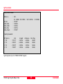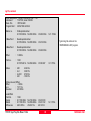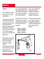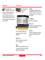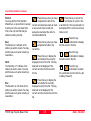
1
20
30
40
50
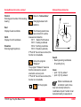
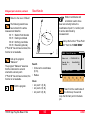
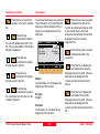
TPS1100 Professional Series
Application Programs Reference Manual
Version 2.2
English
TPS1100 Professional Series
Congratulations on your purchase of your programs for a
TPS1100 Professional Series.
For safe system use, pay attention to the important safety regulations
in the "System" instructions (refer to chapter "Safety directions").
Read carefully through the User's Manual before you switch on the
instrument.
TPS1100 - Appl. Prog. Ref. Manual 2.2.0en
2
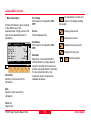
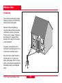
Product identification
The instrument model and serial number of your product are indicated on the
label in the battery compartment.
Enter the model and serial number in your manual and always refer to this
information when you need to contact your agency or authorized service
workshop.
TPS1100 - Appl. Prog. Ref. Manual 2.2.0en
Type:
Serial no.:
SW version:
Language:
3
Product identification
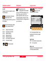
Used Symbols
The symbols used in this User's Manual have the following
meanings:
DANGER:
Indicates an imminently hazardous situation which, if not
avoided, will result in death or serious injury.
WARNING:
Indicates a potentially hazardous situation or an unintended
use which, if not avoided, could result in death or serious
injury.
CAUTION:
Indicates a potentially hazardous situation or an unintended
use which, if not avoided, may result in minor or moderate
injury and / or appreciable material, financial and
environmental damage.
Important paragraphs which must be adhered to in practice
as they enable the product to be used in a technically
correct and efficient manner.
TPS1100 - Appl. Prog. Ref. Manual 2.2.0en
4
Used Symbols
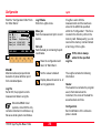
View of Chapters
Contents .................................................................................................. 6
Introduction ........................................................................................... 11
Orientation and Height Transfer ......................................................... 12
Resection ............................................................................................... 22
Tie Distance ........................................................................................... 30
Stakeout ................................................................................................. 37
Free Station ........................................................................................... 54
Reference Line ...................................................................................... 66
Remote Height ...................................................................................... 79
Hidden Point ......................................................................................... 83
Area ........................................................................................................ 89
Sets of Angles ....................................................................................... 97
Traverse ............................................................................................... 124
Local Resection .................................................................................. 138
COGO ................................................................................................... 142
Road+ File Editor ................................................................................ 169
Road+ ................................................................................................... 196
Auto Record ........................................................................................ 244
Monitoring ........................................................................................... 251
Reference Plane ................................................................................. 256
DTM-Stakeout ..................................................................................... 266
TPS1100 - Appl. Prog. Ref. Manual 2.2.0en
5
View of Chapters
Contents
Introduction ..................................................11
Tie Distance ................................................. 30
Calling up a program .................................................. 11
Licence Code ............................................................. 11
Introduction ............................................................... 30
Polygonal Mode .............................................................. 30
Radial Mode ................................................................... 30
Orientation and Height Transfer ................ 12
Measure Mode .......................................................... 31
Results ...................................................................... 32
Configuration ............................................................. 33
Introduction ............................................................... 12
Target Point ............................................................... 12
Point List ......................................................................... 13
Configuration Editor ........................................................ 33
Dual-face Measurement ................................................. 34
Log File .......................................................................... 35
Measure Mode .......................................................... 13
Calculation ................................................................ 14
More Information ............................................................ 16
Stakeout ....................................................... 37
Plot ........................................................................... 17
Configuration ............................................................. 18
Introduction ...............................................................
Search Point .............................................................
Manual Stakout .........................................................
Coarse Positioning ....................................................
Configuration Editor ........................................................ 18
Dual-face Measurement ................................................. 20
Log file ............................................................................ 20
Line Offset ...................................................................... 39
Orthogonal ...................................................................... 40
Azimuth and Distance ..................................................... 41
Resection ..................................................... 22
Introduction ...............................................................
Station Data ..............................................................
Target Point ...............................................................
Measure Mode ..........................................................
Calculation ................................................................
Compare results ........................................................
Configuration .............................................................
22
22
23
23
24
25
26
Stakeout ................................................................... 42
Polar Stakeout ................................................................ 42
Orthogonal Stakeout ....................................................... 44
Stakeout with auxiliary points .......................................... 45
Stakeut from Coordinate Differences .............................. 47
Select Stakeout Method ............................................. 48
Plot ........................................................................... 51
Configuration ............................................................. 51
Configuration Editor ........................................................ 26
Dual-face Measurement ................................................. 27
Log File .......................................................................... 28
TPS1100 - Appl. Prog. Ref. Manual 2.2.0en
37
37
38
38
Log File .......................................................................... 52
6
Contents
Contents, continued
Free Station ................................................. 54
Configuration ............................................................. 75
Introduction ............................................................... 54
Station Data .............................................................. 54
Target Point ............................................................... 55
Configuration Editor ........................................................ 75
Log File .......................................................................... 77
Remote Height ............................................. 79
Point List ......................................................................... 55
Introduction ...............................................................
Measure Base Point ..................................................
Measure Remote Point ..............................................
Configuration .............................................................
Measure Mode .......................................................... 56
Calculation ................................................................ 56
Compare results ............................................................. 58
More Information ............................................................ 59
79
79
81
82
Hidden Point ................................................ 83
Plot ........................................................................... 60
Configuration ............................................................. 61
Introduction ...............................................................
Measure Rod ............................................................
Result .......................................................................
Configuration .............................................................
Configuration Editor ........................................................ 61
Dual-face Measurement ................................................. 62
Log File .......................................................................... 63
83
84
85
86
Example of Measurement data ....................................... 87
Logfile ............................................................................. 87
Reference Line ............................................ 66
Introduction ............................................................... 66
Application notes ....................................................... 88
Constant reference elevation .......................................... 67
Interpolated reference elevation ..................................... 67
Area .............................................................. 89
Reference Line Menu ................................................ 68
Baseline Points ......................................................... 68
Introduction ............................................................... 89
Measure Mode .......................................................... 89
Determine Base Points ................................................... 68
Straight line .................................................................... 89
Arcs ................................................................................ 90
Calculation ..................................................................... 92
Define Reference Line ............................................... 69
Reference Line Results ............................................. 70
Line and Offset .......................................................... 72
Plot ........................................................................... 93
Configuration ............................................................. 94
Enter L&O values ........................................................... 72
L&O Results dialog .................................................... 73
Method Dialog ........................................................... 74
TPS1100 - Appl. Prog. Ref. Manual 2.2.0en
Configuration Editor ........................................................ 94
Dual-face Measurement ................................................. 95
Log File .......................................................................... 95
7
Contents
Contents, continued
Sets of Angles ............................................. 97
Local Resection ......................................... 138
Introduction ............................................................... 97
Sets Menu ................................................................. 98
Introduction .............................................................
Station Data ............................................................
Target Point .............................................................
Calculation ..............................................................
Configuration ...........................................................
Sets menu ...................................................................... 98
Measure Mode ................................................................ 98
Calculate Mode ....................................................... 106
Examples and used formulae ................................... 114
Configuration ............................................................ 116
138
138
139
139
140
Configuration Editor ...................................................... 140
Dual-face Measurement ............................................... 141
Configuration Editor ...................................................... 116
COGO ......................................................... 142
Log File .................................................................... 118
Introduction .............................................................
Configuration ...........................................................
Function selection (COGO Menu) ............................
Inverse (polar calculation) ........................................
Traverse ..................................................................
Example of Logfile Data ................................................ 118
Traverse ..................................................... 124
Introduction ............................................................. 124
Traverse Menu ........................................................ 125
Traverse Menu .............................................................. 125
New traverse ................................................................ 125
Occupy station .............................................................. 129
Traverse Point / Sideshot Point ..................................... 130
Close traverse .............................................................. 131
142
143
144
144
146
Defining direction by magnetic bearing ......................... 147
Defining direction by Azimuth ....................................... 148
Defining horizontal distance .......................................... 149
Traverse results ............................................................ 150
Intersections ............................................................ 151
Plot ......................................................................... 133
Configuration ........................................................... 134
Bearing-Bearing Intersection ........................................ 151
Bearing-Distance Intersection ....................................... 154
Distance-Distance Intersection ..................................... 157
Intersection by Points ................................................... 160
Configuration Editor ...................................................... 134
Dual-face Measurement ............................................... 134
Multiple Measurement .................................................. 135
Log File ........................................................................ 136
Offsets .................................................................... 161
Distance-Offset ............................................................. 162
Orthogonal point calculation ......................................... 164
Three Point Arc ....................................................... 167
TPS1100 - Appl. Prog. Ref. Manual 2.2.0en
8
Contents, continued
Road+ File Editor ....................................... 169
Header Record ............................................................. 193
Insert Station Equation ................................................. 193
Search .......................................................................... 193
Introduction ............................................................. 169
Open file ................................................................. 173
Coordinate Data Files .............................................. 174
Cross Section Assignments ..................................... 194
New Coordinate File ..................................................... 174
Insert Point Coordinates ............................................... 175
Insert Station Coordinates ............................................ 176
Insert Code Block ......................................................... 178
Search .......................................................................... 179
Road+ ......................................................... 196
New Cross-section Assignment File ............................. 194
Header Record ............................................................. 194
Insert Cross-section Assignment .................................. 195
Search .......................................................................... 195
Horizontal Alignment Files ....................................... 179
Introduction ............................................................. 196
New Horizontal Alignment File ...................................... 179
Header Record ............................................................. 180
Insert Tangent ............................................................... 181
Insert Circular Curve ..................................................... 183
Search .......................................................................... 184
Alignment Definition ...................................................... 196
Data Files ..................................................................... 196
Creating Data Files ....................................................... 199
Program Overview ........................................................ 200
Getting started ......................................................... 200
Configuration ........................................................... 201
Select Alignment Files ............................................. 202
Vertical Alignments .................................................. 184
New Vertical Alignment File .......................................... 184
Header Record ............................................................. 185
Insert Tangent ............................................................... 186
Insert Circular Curve ..................................................... 187
Insert Parabola ............................................................. 188
Search .......................................................................... 189
Horizontal Alignment File .............................................. 203
Vertical Alignment File .................................................. 203
Cross Section/template File .......................................... 203
Cross Section Assignment File ..................................... 204
Station Equation File .................................................... 207
File Checking ................................................................ 209
Cross Section .......................................................... 190
New Cross Section File ................................................ 190
Header Record ............................................................. 190
Insert Cross Section Point ............................................ 191
Search .......................................................................... 192
Stakeout Using Horizontal Offset ............................. 210
Preparing for the example ............................................. 210
Sta? .............................................................................. 215
Select Template point and offset ................................... 216
Stakeout and Record point ........................................... 219
Station Equations .................................................... 192
New Station Equation File ............................................. 192
TPS1100 - Appl. Prog. Ref. Manual 2.2.0en
9
Contents, continued
Horizontal Offset Stake Out Summary...................... 222
Select Alignment Files .................................................. 222
Set offset value and select point to stakeout ................. 222
Stakeout the point ......................................................... 223
Select new chainage .................................................... 223
Timer selection ........................................................ 255
Point measurement ................................................. 255
Reference Plane ........................................ 256
Introduction ............................................................. 256
Reference Plane Menu ............................................ 257
Local system - Plane definitions ............................... 258
Slope Staking .......................................................... 224
Reference Point ............................................................ 227
Vertical Plane ............................................................... 258
Tilted Plane ................................................................... 258
Data Formats .......................................................... 229
Horizontal Alignment .................................................... 229
Vertical Alignment ......................................................... 232
Cross Sections ............................................................. 235
Cross Sections Assignments ........................................ 238
Station Equations ......................................................... 240
Log File ........................................................................ 241
Define Points ........................................................... 259
Define Local Plane .................................................. 260
Results Dialog .............................................................. 260
Offset Dialog ................................................................. 261
Point Measurement ................................................. 261
Instrument system ................................................... 262
Auto Record ............................................... 244
Define Instrument Plane ............................................... 262
Introduction ............................................................. 244
Configuration Options .............................................. 244
Point Measurement ................................................. 263
Configuration ........................................................... 264
Notes on Configuration ................................................. 246
Measurement and Recording ................................... 248
Notes on Measurement ................................................ 250
Logfile ........................................................................... 264
DTM-Stakeout ............................................ 266
Introduction .............................................................
Select DTM File ......................................................
Measurement Dialog ...............................................
Data Formats ..........................................................
Example of Logfile Data ........................................... 250
Monitoring .................................................. 251
Introduction .............................................................
Main menu ..............................................................
Selecting Points .......................................................
Measurement menu ................................................
Selecting the points to be measured ........................
TPS1100 - Appl. Prog. Ref. Manual 2.2.0en
251
252
252
253
254
266
266
267
268
DXF-Format .................................................................. 268
Leica GSI - Format ....................................................... 269
Log File ................................................................... 271
10
Introduction
The electronic theodolites and total
stations in the TPS System 1100 are
equipped with programs for
processing field data and controlpoint coordinates. The systems are
therefore highly functional and
classical survey tasks are simplified
appreciably.
All program sequences are based on
a unified structure. The clearlydesigned display with the function
keys makes learning easy. Each
program has a configuration dialog.
In this dialog, the user can match
program-specific parameters to
changes in requirements and
sequences. The various possibilites
are described in the instructions for
the individual programs.
TPS1100 - Appl. Prog. Ref. Manual 2.2.0en
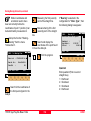
Calling up a program
Licence Code
The TPS1100 keyboard is equipped
When starting certain programs, it
can happen that a licence code is
requested. The licence code is
needed to run the program with full
functionality.
Without licence code, you can run
the programs in a demonstration
version, but you will not be able to
calculate and store the results.
with a program key:
Pressing this key will display a menu
with all programs installed on your
instrument.
The licence code is available from
your Leica Geosystems agency, who
will inform you about licence fees for
code protected programs.
11
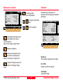
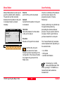
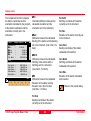
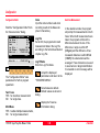
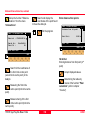
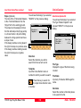
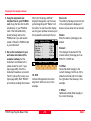
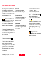
Introduction
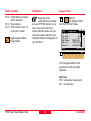
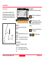
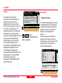
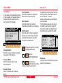
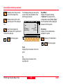
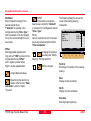
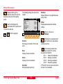
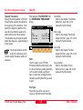
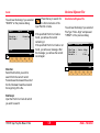
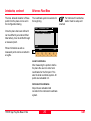
Orientation and Height Transfer
Introduction
Target Point
This manual describes the "Orientation
and Height Transfer" program of the
TPS1100 Professional series.
Enter the target point number and
height of the reflector
=0
:
:
MC
Target Point
Point Id
Refl.Ht.
Hz
12
1.300
m
Dist1
Hz1
Hz2
1st target
(E, N)
∆Elev.
The instrument must be set up on a
known point. The program
"ORIENTATION" calculates an
angular correction for the instruments
horizontal circle, so that 0.0000 of the
horizontal circle corresponds with
grid north (Orientation correction),
using reference points with known
Easting and Northing.
TPS1100 - Appl. Prog. Ref. Manual 2.2.0en
SEARC LIST
CONF
Dist2
2nd target
(E, N, H.)
1100pr02
Orientation
Ori\
For simultaneous determination of
the station elevation, height of
instrument and height of reflector
must already have been input and
the elevation of the target points
must be known. You may use target
points with elevation only.
The program handles a maximum of
10 points.
12
VIEW
QUIT
Retrieve the coordinates of
the target point. Search the
coordinates of the point entered in
the active data job and go to the
measure mode.
Define a list of target points
and the measurement
sequence. For further use: selection
of points from the list is possible.
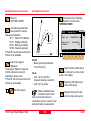
Orientation and Height Transfer
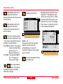
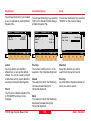
Point List
Measure Mode
Displays the previous point
from the list of points entered.
Note that this key will not be available
until there is at least one point in the
list.
Enter a maximum of 10 points. The
same point can be retrieved several
times.
This dialog is similar to the TPS
1000’s basic "Measure Mode" dialog.
Once a measurement is taken, the
program will return to the dialog
"Target Point" to acquire the next
point for measuring.
Displays the next point in the
list of points entered. Note
that this key will not be available until
there is at least one point in the list.
Search and display the
coordinates of the point found
in the active data job.
Ori\
Point
Point
Point
Point
Point
Point
1
2
3
4
5
6
Point List
:
:
:
:
:
:
1
2
3
4
5
6
:
:
:
:
7
8
9
0
MC
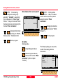
Target Point, continued
If the orientation correction can be
calculated successfully from any of
the first measurements, the ∆Hz and
∆V values are displayed for further
entered target point. Motorized
theodolites will automatically drive the
telescope to the target point.
CONT
Point 7
Point 8
Point 9
Point 10
QUIT
Run the calculation.
Note, the
key will be
assigned after the first measurement.
Return to the dialog "Target
Point".
Start the
"CONFIGURATION"
TPS1100 - Appl. Prog. Ref. Manual 2.2.0en
13
Orientation and Height Transfer
Measure mode, continued
ALL
DIST
REC
Enter target data.
(see User Manual)
m
m
Change the theodolite
face.
QUIT
Exit the program.
CONT TARGT
I<>II
Calculates the orientation, the
elevation and the respective standard
deviations.
Ori\
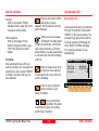
Results (Robust)
Station Id
:
10
No. of Pts. :
5
Inst.Ht.
:
1.635
East
:
2134.234
North
:
4723.365
Elevation
:
521.643
S.ORI S.HT STORE MEAS
Simultaneously measure and
record data on the active
recording device.
Return to the dialog "Target Point".
Hz Ori.
σ Elev.
σ Hz Ori.
:
:
:
LSQRS
MC
MC
Ori\
Measure
Point Id
:
1
HZ
:
216°55'50"
V
:
71°16'20"
Refl. Ht. :
1.300
Slope Dist :
385.231
∆HZ
:
-----
Calculation
m
m
m
m
m
MORE
2°12'34''
0.010
0°00'03*
PLOT
m
QUIT
Measure a distance.
Record the measurement on
the active recording device.
Return to the dialog "Target Point".
Station Id.
Point number assigned to the station
Accept the measurement and
return to the dialog "Target
No. of Pts.
Number of points measured
Point".
Inst.Height
Instrument Height
TPS1100 - Appl. Prog. Ref. Manual 2.2.0en
14
Orientation and Height Transfer
Calculation, continued
East
Easting of the station
North
Northing of the station
Elevation
Calculated elevation of the station
Orientation
Oriented direction
Set orientation on the
instrument.
Note that once this key has been
pressed it will not be possible to
execute more measurements.
Set station elevation on the
instrument.
Note that once this key has been
pressed it will not be possible to
execute more measurements.
σ Elevation
Standard deviation of the Elevation
σ Orient
Standard deviation of the Orientation
TPS1100 - Appl. Prog. Ref. Manual 2.2.0en
Record the following results
into the active measurement
job
WI
WI
WI
WI
WI
WI
WI
11
25
84
85
86
87
88
Measure more points. The
program will recall the
"TARGET POINT" dialog.
Show the results of individual
measurements on the screen
(see dialog "More Information").
Select between the
"Robust" method and
the "Least Square" method.
Sketch of the station
and the reference
points used.
Station Point Number
Orientation correction
Station Easting
Station Northing
Station Elevation
Last reflector height used
Instrument Height
15
Orientation and Height Transfer
More Information
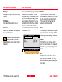
Ori\
More Info
Point Id
Pt. Status
Error flag
∆ Hz
∆ Dist.
:
:
:
:
:
RECLC
-->
<--
∆ Ht
Refl. Ht.
East
North
Elevation
:
:
:
:
:
2/10
10
Point01
NONE
0°00'03"
0.050 m
MEAS
DEL
0.020
1.555
991.427
1995.162
402.466
MC
Display the residuals of individual
measurements. You can also disable
points from the calculation of
orientation or height as well as delete
erroneous measured points.
BACK
m
m
m
m
m
TPS1100 - Appl. Prog. Ref. Manual 2.2.0en
2/10
Sequence number of the current
point and total number of points in
the measurement set. The scroll bar
shows the sequential position of the
measurements, graphically.
Status
Use this measurement for calculation
(ON/OFF).
Error Flag
Identified erroneous measurements.
Possible values are:
NONE
measurement is OK
HZ
horizontal angle error
DIST
distance error
HT
height difference error
The flags may also be combined, i.e.
DIST + HZ
Pt. Status
ON Measurements to target point
used for calculation.
Ignore Elev.
Target point elevation disabled:
measurements for elevation
determination not used in
calculation.
OFF Target point disabled:
measurements to point NOT
used for calculation.
16
Orientation and Height Transfer
Plot
∆ Hz.
Difference between calculated and
measured horizontal angle
∆ Distance
Difference between calculated and
measured distance
∆ Height
Difference between calculated and
measured height
Refl. Ht.:
Reflector height used for
the target point
Easting, Northing, Elevation:
Target coordinates used
Refl. Ht.
Reflector height used for the target
point
Recalculate the result.
Scroll to the measurements
of the previous point.
Scroll to the measurements
of the following point.
Measure more points. Return
to the dialog "Target Point".
Delete a point from the set of
measurements. You can now
measure a new point in its place.
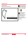
Generates a plot showing the
measurement configuration.
The station point is in the center and
the top of the sketch shows the
direction of grid north. The sketch is
true in angular but not true in
distances.
Points are numbered sequentially in
the order in witch they were
measured.
Points not used in the calculation are
marked with a dotted line.
Ori\
PLOT
2
Return to the results dialog
without changes.
MC
More Information, continued
1
3
5
4
Exit the program.
RECLC
MEAS
QUIT
East, North, Elevation
Target coordinates used.
Recalculate the result and
return to the dialog
"CALCULATION RESULTS".
TPS1100 - Appl. Prog. Ref. Manual 2.2.0en
17
Orientation and Height Transfer
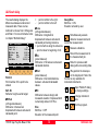
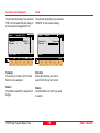
Configuration
Configuration Editor
Measure more points. The
program will recall the
"TARGET POINT" dialog.
Depending on the configuration that
is loaded onto your TPS1100
instrument, you may not see some or
all of the options referred to below.
See your Leica Geosystems dealer
for more information about the
configuration of your instrument.
Start the "Configuration
Editor" from the
"TARGET POINT" dialog.
...
Toggle any point ON or
OFF by pressing the numeric key
corresponding to the sequence
number of the point.
Note, that
Ori\
Configuration
Hz Ori. Acc :
0°00'32"
Ht Acc TP
:
0.0250 m
Pos Acc TP
:
0.0250 m
Tow faces
:
NO
User Disp.
:
NO
Log File
:
OFF
CONT
represents point 10.
Log FlName
Meas Job
Data Job
Exit the program.
DFLT
:
:
:
MC
Plot, continued
INFO
ORIENT.LOG
FILE01.GSI
FILE02.GSI
QUIT
The "Configuration Editor "sets
parameters for further program
operations:
Hz Ori Acc
Limit for the standard deviation of the
orientation. The orientation is
regarded as "error free", if the
computed standard deviation of the
orientation is within twice the entered
value.
TPS1100 - Appl. Prog. Ref. Manual 2.2.0en
18
Orientation and Height Transfer
Configuration Editor, continued
Ht Acc TP
Height accuracy of the target points.
The entered value, is used as an "a
priori" accuracy in the calculation.
The height is regarded as "error
free", if the computed standard
deviation is within twice the entered
value.
Pos Acc TP
Position accuracy of the target points.
The entered value, is used as an "a
priori" accuracy in the calculation.
The position is regarded as "error
free", if the computed standard
deviation is within twice the entered
value.
User Disp
YES: The same display mask as the
one used in the system measurement dialog (MEAS) is used for
measurements with "Orientation and
Height Transfer".
NO: The "Orientation and Height
Transfer" default display applies.
Log File
ON, records measurements in a LogFile. The format is described in
chapter "Log file".
Data Job
Selection of the data job containing
the fix point coordinates (control
data).
Store the current
configuration and proceed to
the dialog "TARGET POINT".
Set the values to default.
Log FlName
Enter the Log File Name.
Two Faces
YES for dual-face measurement,
NO for single-face.
TPS1100 - Appl. Prog. Ref. Manual 2.2.0en
Meas. Job
Selection of the measurement job for
recording measurements.
Displays date and version.
Exit the program.
19
Orientation and Height Transfer
Dual-face Measurement
Log file
In the dual-face mode, the program
will prompt for measurements in both
faces. When both measurements are
taken, the program will check the
difference between the two. If the
difference in angle is within 27'
(0.5 gon) and the difference of two
measured distances is within 0.5 m
(1.64 ft), the observations will be
averaged. These tolerances are used
to avoid errors in target identification.
If exceeded an error message will be
displayed.
If "Log File" is set to "ON" the
measurements and the results are
stored in the ASCII-file specified
within the "Configuration Editor". This
file is created in the directory LOG on
the memory card. Subsequently, you
can read the memory card on your
PC and obtain a hard copy of the
Log-file.
Record
For each measurement, a record will
be stored containing:
• Station coordinates
• station height,
• orientation correction
• standard deviations
for height and orientation
correction
Data will always be
appended to the specified
Log-file.
The residuals for:
• horizontal angles,
• heights and
• measured distances
are also listed.
The Log-file contains the following
information:
Header
The header line will contain the
program used, information about the
instrument, the name of the data file
as well as date and time.
TPS1100 - Appl. Prog. Ref. Manual 2.2.0en
20
Orientation and Height Transfer
Log file, continued
Leica Geosystems Program Orientation and Height Transfer V 1.00
Instrument
:
TCA1103, Serial 102999
Meas. File
:
MYFILE.GSI
Program Start
:
20/04/1998 at 09:42
Station no.
:
2000
E= -0.0006m N= -0.0002m ELV= 398.3961m
hi= 1.6000m
Station Elev.
Ori.Corr.
S.Dev. Elev.
S.Dev. Orient.
:
:
:
:
398.3929m
40'36"
0.0035m
0°00'04"
3 point(s) measured
:
Using Robust Solution
##
1
2
3
Point no.
500
501
502
∆ Hz
-0°00'55"
-0°00'48"
0°00'52"
∆ Height
0.0026m
0.0044m
-0.0070m
∆ Distance
0.0020m
0.0016m
-0.0000m
Error Flag
NONE
NONE
NONE
Typical log file entry in the "Orientation and Height Transfer" program
TPS1100 - Appl. Prog. Ref. Manual 2.2.0en
21
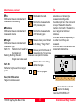
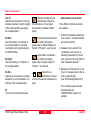
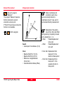
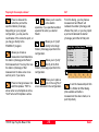
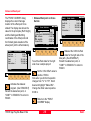
Orientation and Height Transfer
Resection
Introduction
Station Data
This manual describes the
"Resection" program of the TPS1100
Professional Series.
Enter station point number and height
of the instrument.
t2
Hz1
Dist
MC
Station Data
Station Id:
Inst. Ht. :
=0
Hz
Dis
Orientation
Resec\
1
1.555 m
1
CONT
2st target
CONF
QUIT
The program can be used to reduce
the three-dimensional coordinates for
the instrument station and the
orientation of the horizontal circle
from measurements to 2 target
points with know Easting and
Northing. To compute the position
coordinates, at least the distances
and the directions for both points are
necessary.
TPS1100 - Appl. Prog. Ref. Manual 2.2.0en
1100pr03
1st target
Hz2
For simultaneous determination of
the station elevation, height of
instrument and height of reflector
must already have been input and
the elevation of the target points
must be known.
Proceed to the dialog "Target
Point".
Start the
"Configuration".
The program allows measurement in
single or dual-face mode.
22
Resection
Measure Mode
Enter the target point number and
height of the reflector.
This dialog is similar to the
TPS1100’s basic "Measure Mode"
dialog. Once a measurement is
taken, the program will return to the
dialog "Target Point" to acquire the
next point for measuring.
Target Point
Point Id :
Refl. Ht. :
SEARC
MC
Resec\
30
1.300 m
VIEW
Search the coordinates of the
point entered from the active
data job and go to the measure
mode.
Resec\
Measure
Point Id :
1
Hz
:
286°55’50’’
V
:
91°16’20’’
Refl. Ht. :
0.000 m
Slope Dist:
----ALL
DIST
REC
MC
Target Point
CONT TARGT
I<>II
QUIT
Record the measurement in
the active measurement job.
Return to the dialog "TARGET
POINT".
Accept the measurement and
return to the dialog "Target
Point".
Enter target data.
(See User Manual)
Change the theodolite
face.
Exit the program.
Search and display the
coordinates of the point found
in the active data job.
Simultaneously measure and
record data in the active
measurement job. Return to the
dialog "TARGET POINT".
Measure a distance.
TPS1100 - Appl. Prog. Ref. Manual 2.2.0en
23
Resection
Calculation
Resec\
Results (L.Sqrs)
Station Id:
1
No. of Pts:
2
Inst. Ht. :
1.635 m
East
:
2134.234 m
North
:
4231.365 m
Elevation :
580.643 m
SET
Hz Ori.
σ East
σ North
σ Elev.
σ Hz Ori.
STORE
:
:
:
:
:
East
Calculated Easting for the station.
MC
In this dialog the calculated station
coordinates are shown with the
orientation.
COMP
2°12’34’’
0.003 m
0.005 m
0.005 m
0°00’03’’
North
Calculated Northing for the station.
Elevation
Calculated elevation for the station
Hz Ori.
Oriented direction
σEast
Standard deviation of Easting
σNorth
Standard deviation of Northing
Station Id
Station point number
No. of Pts
Number of points measured
Set orientation and station
coordinates on the
instrument.
σElev
Standard deviation of the Elevation
Record the following results
in the active measurement
job:
WI
WI
WI
WI
WI
WI
WI
11
25
84
85
86
87
88
Station Point Number
Orientation correction
Station Easting
Station Northing
Station Elevation
Last reflector height used
Instrument Height
Compare the Resection
results to the station
coordinates and orientation currently
set in the instrument.
σHz Ori.
Standard deviation of the Orientation
Exit the program.
Inst.Ht.
Instrument Height
TPS1100 - Appl. Prog. Ref. Manual 2.2.0en
24
Resection
Compare results
Resec\
Compare Results
Station Id:
1
∆ Ori.
:
0°00'05"
∆ East
:
-0.002
∆ North
:
0.006
∆ Ht.
:
-0.020
Fix East :
2134.236
MC
The comparison function compares
the station coordinates and the
orientation calculated by the program
to the station coordinates and the
orientation currently set in the
instrument.
m
m
m
m
CONT
Fix North :
Fix Elev. :
Calc.East :
Calc.North:
Calc.Elev.:
4231.359
580.663
2134.234
4231.365
580.643
m
m
m
m
m
QUIT
∆Ori
Orientation difference between the
calculated orientation and the
orientation set in the instrument.
∆East
Difference between the calculated
Easting of the station and the Easting
set in the intrument.
(Calc. East - Fix East)
∆North
Difference between the calculated
Northing of the station and the
Northing set in the intrument.
(Calc.North - Fix North)
∆Ht.
Difference between the calculated
Elevation of the station and the
Elevation set in the intrument.
(Calc.Elev. - Fix Elev.)
Fix North
Northing coordinate of the station
currently set in the intrument.
Fix Elev.
Elevation of the station currently set
in the intrument.
Calc. East
Easting coordinate of the station
calculated with resection.
Calc.North
Northing coordinate of the station
calculated with resection.
Calc.Elev.
Elevation of the station calculated
with resection.
Return to the results dialog.
Fix East
Easting coordinate of the station
currently set in the intrument.
TPS1100 - Appl. Prog. Ref. Manual 2.2.0en
25
Resection
Configuration Editor
Depending on the
configuration that is loaded
onto your TPS1100 instrument, you
may not see some or all of the
options referred to below. See your
Leica Geosystems dealer for more
information about the configuration of
your instrument.
Start the "Configuration
Editor" from the "Station
DATA" dialog.
Resec\
Configuration
Hz Ori.Acc:
0°00’32’’
Ht Acc TP :
0.025 m
Pos Acc TP:
0.025 m
Two Faces :
NO
User Disp.:
NO
Log File :
OFF
CONT
Log FlName:
Meas Job :
Data Job :
MC
Configuration
DEFLT INFO
RESEC.LOG
FILE01.GSI
FILE02.GSI
The "Configuration Editor" sets
parameters for further program
operations:
Hz Ori Acc
Limit for the standard deviation of the
orientation. The orientation is
regarded as "error free", if the
computed standard deviation of the
orientation is within twice the entered
value.
TPS1100 - Appl. Prog. Ref. Manual 2.2.0en
26
Ht Acc TP
Height accuracy of the target points.
The entered value, is used as an "a
priori" accuracy in the calculation.
The height is regarded as "error
free", if the computed standard
deviation is within twice the entered
value.
Posn Acc TP
Position accuracy of the target points.
The entered value, is used as an "a
priori" accuracy in the calculation.
The position is regarded as "error
free", if the computed standard
deviation is within twice the entered
value.
Two Faces
YES for dual-face measurement,
NO for single-face.
Resection
Configuration Editor, continued
UserDisp.
YES The same display mask as the
one used in the system
measurement dialog (MEAS)
is used for measurements with
"RESECTION".
NO The "RESECTION" default
display applies.
Log File
Set to ON, the program will record
measurement data in a log file as
described in chapter "Log File".
Dual-face Measurement
Log FlName
Enter the Log File Name.
Meas. Job
Selection of the measurement job for
recording measurements.
Data Job
Selection of the data job containing
the fix point coordinates (control
data).
Store the current
configuration and proceed to
the dialog "STATION DATA".
In the dual-face mode, the program
will prompt for measurements in both
faces. When both measurements are
taken, the program will check the
difference between the two. If the
difference in angle is within 27'
(0.5 gon) and the difference of two
measured distances is within 0.5 m
(1.64 ft), the observations will be
averaged.
These tolerances are used to avoid
errors in target identification.
If exceeded an error message will be
displayed.
Set the value to the default
Displays date and version.
Exit the program.
TPS1100 - Appl. Prog. Ref. Manual 2.2.0en
27
Resection
Log File
If "Log File" is set to "ON" the
measurements and the results are
stored in the ASCII-file specified
within the "Configuration Editor". This
file is created in the directory LOG on
the memory card. Subsequently, you
can read the memory card on your
PC and obtain a hard copy of the
Log-file.
Record
For each measurement, a record will
be stored containing:
Station coordinates and orientation
correction, standard deviation for
Easting, Northing, Height of station
and orientation correction.
The residuals for horizontal angles,
heights and measured distances are
also listed.
Data will always be
appended to the specified
Log-file.
The Log-file contains the following
information:
Header
The header line will contain the
program used, information about the
instrument, the name of the data file
as well as date and time.
TPS1100 - Appl. Prog. Ref. Manual 2.2.0en
28
Resection
Log File, continued
Leica Geosystems Program Resection V 1.00
Instrument
:
TCA1103, Serial 102999
Meas. File
:
MYFILE.GSI
Program Start
:
20/04/1998 at 09:42
Using Least-Squares Solution
Station no.
:
2000
E= -0.0011m N= -0.0006m ELV= 398.3951m
hi= 1.6000m
Ori.Corr.
S.Dev. East
S.Dev. North
S.Dev. Elev.
S.Dev. Orient.
;
:
:
:
:
240°50'51"
0.0003m
0.0003m
0.0047m
0°00'49"
2 point(s) measured:
## Point no.
1 500
2 501
∆ Hz
-0°00'55"
-0°00'18"
∆ Height
0.0047m
-0.0047m
∆ Distance
0.0001m
0.0002m
Error Flag
NONE
NONE
Typical log file entry in the "Resection" program
TPS1100 - Appl. Prog. Ref. Manual 2.2.0en
29
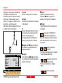
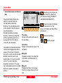
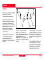
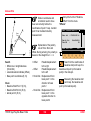
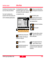
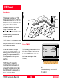
Resection
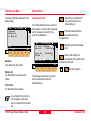
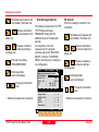
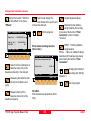
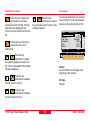
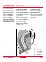
Tie Distance
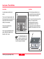
Radial Mode
In Polygonal Mode, the program will
calculate the distance between the
last two points measured (eg. Pt3 Pt4).
In Radial Mode, the program will
calculate the distance between the
last point measured (called a Radial
Point) (Pt2, Pt3 ...) and a fixed
Center Point (Pt1).
°0
0'0
0''
N
=0
This manual describes the "Tie
Distance" program of the TPS 1100
Professional series.
The program calculates the length
and azimuth of a line connecting two
points.
Polygonal or Radial methods can be
used as shown in the illustrations.
Polygonal Mode
Hz
Introduction
Hz 2-3
2
Hz 1-2
1
3
Hz 3-4
Tie Dist 1-2
1100pr04
Tie Dist 2-3
Tie Dist 3-4
4
''
N
=0
1
Az
14
1-
1-
2
3
Center
Point
Tie Dist 1-2
2
Tie Dist 1-3
Tie D
ist 1
-4
3
4
1100pr05
°00
'00
Az
Az
Hz
The data for the points can either be
measured or retrieved from the
selected data job. Measured points
and points retrieved from the
selected data job can be used
together in the calculations, if the
station coordinates and orientation
are set correctly.
Toggling between Polygonal and
Radial Mode at any time while
working is possible.
TPS1100 - Appl. Prog. Ref. Manual 2.2.0en
30
Tie Distance
Measure Mode
TieD\
First Point
Point Id :
546
Refl. Ht. :
1.654 m
Hz
:
230°45'23''
V
:
4°52'35''
Slope Dist:
----- m
Ht. Diff. :
----- m
ALL
DIST
East
:
North
:
Elevation :
CONF
REC
MC
This dialog is used in accordance
with the settings of the system
function "Measure & Record" or
according to the dialog shown below.
CONT TARGT IMPORT
----- m
----- m
----- m
I<>II VIEW
QUIT
The input for the start point is only
possible after the program start or
in the dialog
with the function
"RADIAL MODE".
For all following points the program
requests (NEXT POINT).
The dialog for the following points is
identical with dialog above, except
for the title.
TPS1100 - Appl. Prog. Ref. Manual 2.2.0en
Simultaneously measure and
record in the active
measurement job. Proceed with the
dialog "NEXT POINT". If the second
point has already been measured, the
program will proceed to the "Result"
dialog.
Measure a distance.
Record the
measurement in the active
measurement job and proceed with
the dialog "NEXT POINT". If the
second point has already been
measured, the program will proceed
to the "RESULT" dialog.
Enter the target data.
(see User Manual)
Import target coordinates.
Start the
"Configuration Editor".
Change the theodolite
face.
Exit the program
Measure the distance.
Accept the
measurement without recording. If
the second point has already been
measured, the program will proceed
with the "RESULT" dialog.
31
Tie Distance
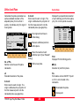
Results
This dialog shows the results
computed from the last two points,
which can be measured or retrieved
from the active file. The same results
are calculated for both methods.
Using "Polygon Mode" the
calculations are always based on the
last two points, where as the "Radial
Mode" always uses the first point as
a reference point.
NEXT RESET STORE
∆ East
∆ North
:
:
MC
TieD\ Radial Mode
Center Pt :
12
Radial Pt :
13
Hori.Dist :
4.567
Azimuth
:
342°52'35''
∆ Height
:
2.543
Slope Dist:
4.946
Center Pt.
Point number of the center point
Radial Pt.
Point number of the radial point
Hori.Dist
Horizontal distance between the two
points
Azimuth
Azimuth from point 1 to point 2
∆ Height
Height difference between point 1
and point 2 (H2 - H1).
POLY
Slope Dist
Slope distance between the two
points.
22.432
50.083
QUIT
TPS1100 - Appl. Prog. Ref. Manual 2.2.0en
∆ East
Difference in Easting between point 1
and point 2 (E2 - E1).
The grid coordinates are only valid
for oriented instruments set up on a
known point.
32
∆ North
Difference Northing between point 1
and point 2 (N2 - N1).
Note, the grid coordinates are only
relevant for oriented instruments set
up on a known point.
Return to the dialog "NEXT
POINT" and measure the
next point.
Delete previous inputs.
Proceed with the dialog
"FIRST POINT" to enter a new
reference point. This function is
available for "RADIAL MODE" only.
Record the following results
in the active measurement
job:
WI 11
WI 25
WI 35
Point number of point 2 or
radial point number
Azimuth from point1 to point 2
Horizontal distance
Tie Distance
Results, continued
Configuration
Configuration Editor
WI 37
Depending on the
configuration that is loaded
onto your TPS1100 instrument, you
may not see some or all of the
options referred to below. See your
Leica Geosystems dealer for more
information about the configuration of
your instrument.
Start the
"Configuration Editor"
from the "First Point" dialog.
Toggle between Radial/
Polygon Mode.
TieD\
Configuration
Two Faces :
NO
User Disp.:
NO
Log File :
Off
Log FlName:
TIEDIST.LOG
Meas Job :
FILE01.GSI
Data Job :
FILE02.GSI
CONT
MC
WI 39
WI 79
Height difference between
point 1 and point 2
Slope distance
Point number of point 1 or
center point number
DEFLT INFO
QUIT
The "Configuration Editor" sets
parameters for further program
operations:
Two Faces
YES for dual-face measurement,
NO for single-face.
TPS1100 - Appl. Prog. Ref. Manual 2.2.0en
33
Tie Distance
Configuration Editor, continued
User Disp
YES The same display mask as the
one used in the system
measurement dialog (MEAS)
is used for measurements with
"Tie Distance".
NO The "Tie Distance" default
display applies.
Log File
Set to ON, the program will record
measurement data in the Log File
according to the format described on
chapter "Log File".
Dual-face Measurement
Store the current
configuration and proceed to
the dialog "MEASURE MODE".
Set the values to default.
Displays date and version of
the running application.
Exit the program.
In the dual-face mode, the program
will prompt for measurements in both
faces. When both measurements are
taken, the program will check the
difference between the two. If the
difference in angle is within 27'
(0.5 gon) and the difference of two
measured distances is within 0.5 m
(1.64 ft), the observations will be
averaged. These tolerances are used
to avoid errors in target identification.
If exceeded an error message will be
displayed.
Log FlName
Enter the Log File Name.
Meas. Job
Selection of the measurement job for
recording measurements.
Data Job
Selection of the data job containing
the fix point coordinates (control
data).
TPS1100 - Appl. Prog. Ref. Manual 2.2.0en
34
Tie Distance
Log File
If "Log File" is set to ON the
measurements and the results are
stored in the ASCII-file specified
within the "Configuration Editor". This
file is created in the directory LOG on
the memory card. Subsequently, you
can read the memory card on your
PC and obtain a hard copy of the
Log-file.
Record
For each measurement, a record will
be stored containing :
Point No 1, Point No. 2, Hori. Dist.,
Azimuth, ∆ Height, Slope Dist.
Data will always be
appended to the specified
Log-file.
The Log-file contains the following
information:
Header
The header line will contain the
program used, information about the
instrument, the name of the data file
as well as date and time.
TPS1100 - Appl. Prog. Ref. Manual 2.2.0en
35
Tie Distance
Log File, continued
Leica Geosystems
Instrument
:
Meas. File
:
Program Start
:
Station no.
:
Point No.1
:
Point No.2
:
Point no.1
Point no.2
Hori.Dist.
Azimuth
∆Height
Slope dist.
Point No.2
:
:
:
:
:
:
:
Point No. 1
Point No.2
Hori.Dist.
Azimuth
∆Height
Slope dist.
:
:
:
:
:
:
Program Tie Distance V 1.00
TCA1103, Serial 102999
MYFILE.GSI
20/04/1998 at 09:42
1151
E= 0.0000m
N= 0.0000m
hi= 0.0000m
1020
E= -31.2368m
N= -0.2083mELV=
1030
E= -30.5679m
N= -17.8404m
1020
1030
17.6448m
197°58'40"
3.0572m
17.9077m
1040
E= -57.7040m
N= -0.4265m
1030
1040
32.2430m
336°32'14"
-3.0170m
32.3839m
ELV= 400.0000m
400.0626m
ELV= 403.1198m
H= 400.1028m
Typical log file entry in the "Tie Distance" program (Polygonal Mode)
TPS1100 - Appl. Prog. Ref. Manual 2.2.0en
36
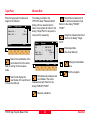
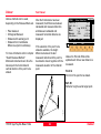
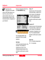
Tie Distance
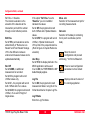
Stakeout
Search Point
This manual describes the
"STAKEOUT" program of the
TPS 1100 Professional series.
The program is used to place marks
in the field at predetermined points.
The "SEARCH POINT" dialog
informs about the active recording
device, the active measurement job
for data storage and the present
point/code.
"STAKEOUT" requires the instrument
to be set up on a known point with
the instrument oriented. The station
point can be determined also with the
programs "FREE STATION" and
"RESECTION".
The easting and the northing of the
point to be staked must be known.
The elevation is optional: the
program permits selection of either
2D or 3D stakeout modes. It is also
possible to stake out points given the
azimuth and the distance from the
station.
The points to be staked can either be
retrieved from the selected data job
or entered manually.
TPS1100 - Appl. Prog. Ref. Manual 2.2.0en
STAKE\
Search Point
Define stakeout point
Data job : FILE01.GSI A:
Search for:
Point Id :
MC
Introduction
CONF
Search and display the
coordinates of the point found
in the active data job.
VIEW
QUIT
Search the coordinates of the
point entered in the active
data job. Proceeds to the Coarse
Positioning mode. Depending on the
configuration of the stakeout method,
the program may proceeds to the
Stake mode.
37
Manually enter the stakeout
point.
Allows program
configuration.
Point Id+E+N
4
SEARC MSTAK INPUT
Manually enter the azimuth
and the distance to the point
to be staked.
If the instrument is in LOCKmode with EDM-mode TRK/
RTRK and no Coarse Mode selected,
pressing F1: SEARC starts the
distance measurement.
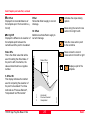
Stakeout
Manual Stakout
Coarse Positioning
STAKE\
Manual Entry
Point Id :
1
Azimuth
:
--°--'--''
Horiz.Dist:
----- m
Elevation :
----- m
MC
Manual Stake allows to enter a point
given the azimuth and the distance.
The azimuth and the horizontal
distance from the station to the point
to be staked must be entered
manually.
Point Id
point Id of the point to be staked.
Azimuth
Azimuth from the station to the point
to be staked.
Horiz.Dist
Horizontal distance from the station
to the point to staked.
Elevation
Elevation of the point to be staked.
STAKE
QUIT
Confirms the entry and
proceeds to the Coarse
Positioning mode. Depending on the
configuration of the stakeout method,
the program may proceed to the
Stake mode.
Once the coordinates of the stakeout
point have been acquired, the
program proceeds to "Coarse
Positioning".
Coarse positioning is an optional step
for approximate positioning,
preceeding the iterative stakeout
process. It may be used to direct the
rod person from the point that has
just been staked to the next point.
The "Coarse Positioning" calculates
various displacements, depending on
the selected mode.
• Line Offset
• Orthogonal
• Azimuth and Distance
If instrument is in LOCKmode with EDM-mode TRK/
RTRK, pressing F1: STAKE from a
Coarse Mode starts a distance
measurement.
TPS1100 - Appl. Prog. Ref. Manual 2.2.0en
38
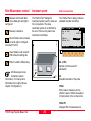
Stakeout
The stakeout values of each point
are computed in relation to the base
formed by the last two points.
If the elevation is known for the point
to be staked out, the height
difference in relation to the last base
point (Pt2), is displayed. In particular,
this method is advantageous for long
objects (traffic routes).
e+
Lin
PLOT
Hz
Present theodolite direction. Note, if
the instrument is oriented and the
azimuth and Hz angle are
corresponding, the instrument is
pointing to the point to be staked.
12
1100pr09
11
TPS1100 - Appl. Prog. Ref. Manual 2.2.0en
METHD
Azimuth
Azimuth from the station to the point
to be staked.
et+
10
STAKE
Point Id
Point Id of the point to be staked.
Values for positioning are
only displayed after two
stakeout points.
Of f s
STAKE\
Line Offset
Point Id :
12
Azimuth
:
90°10'02''
Hz
:
98°34'45''
Line
:
4.105 m
Offset
:
1.250 m
∆ Height
:
0.340 m
MC
Line Offset
Line
Distance along the line defined by the
last two points staked.
39
Offset
Orthogonal offset from the defined
line.
∆Height
Height difference from the last point
staked.
Proceed to "STAKEOUT".
Motorized theodolites can
drive the telescope to the horizontal
and vertical direction of the point to
be staked.
Change stakeout
method. For more
information refer to chapter "Select
Stakeout Method".
Generate a plot of the
stakeout data. For
more information to chapter "Plot".
Exit the program.
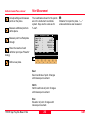
Stakeout
Orthogonal
–
Setting out values are computed as
orthogonal coordinates to the
baseline between instrument station
and prism. If the elevation is also
known, ∆H is given in relation to the
last prism - point measured.
Note, data will be displayed if there is
at least one point measured.
Azimuth
Azimuth from the station to the point
to be staked.
Hz
Present theodolite direction. Note, if
the instrument is oriented and the
azimuth and Hz angle are
corresponding, the instrument is
pointing to the point to be staked.
∆L
en
gth
11
Point Id
Number of the point to be staked.
oss+
12
STAKE\ Orthogonal Stake
Point Id :
12
Azimuth
:
90°10'02''
Hz
:
98°34'45''
∆ Length
:
4.105 m
∆ Cross
:
1.250 m
∆ Height
:
0.340 m
MC
1100pr10
∆C r
∆Length and ∆Cross in relation to
the baseline: last stakeout point instrument station.
∆ Length
In-line distance ∆Length is positive
for points further than the last prism
position measured.
STAKE
METHD
PLOT
TPS1100 - Appl. Prog. Ref. Manual 2.2.0en
∆ Cross
Distance perpendicular to the
baseline. ∆Cross is positive for
points on the right of the baseline.
∆ Height
Height difference from the last point
measured.
Proceed to "STAKEOUT".
Motorized theodolites can
drive the telescope to the horizontal
and vertical direction of the point to
be placed.
Change stakeout
method.
For more information refer to chapter
"Select Stakeout Method".
Generate a plot of the
stakeout data.
For more information on chapter
"Plot".
Exit the program.
40
Stakeout
Azimuth and Distance
This mode defines the point to be
staked in terms of the azimuth and
distance from the theodolite station to
the point.
Azimuth
Azimuth from the station to the point
to be staked.
Hz
=0
°00
'00
"
N
Point Id
Point Id of the point to be staked.
Hz
im
Az
Slo
pe
Hz
Present theodolite direction.
uth
Dis
tan
ce
STAKE\Azimuth and Distance
Point Id :
12
Azimuth
:
30°03'23''
Hz
:
15°43'02''
Slope Dist:
35.60 m
Horiz Dist:
34.97 m
∆ Height
:
0.75 m
MC
1100pr07
12
STAKE
Note, if the instrument is
oriented and the azimuth
and Hz angle are corresponding,
the instrument is pointing to the
point to be staked.
Slope Dist
Slope distance from the instrument
station to the stakeout point.
Horiz. Dist
Horizontal distance from the
instrument station to the stakeout
point.
∆ Height
Height difference from the instrument
station to the stakeout point.
Proceed to "STAKEOUT".
Motorized theodolites can
drive the telescope to the horizontal
and vertical direction of the point to
be placed.
Change stakeout
method.
For more information refer to chapter
"Select Stakeout Method".
Generate a plot of the
stakeout data. For
more information to chapter "Plot".
Exit the program.
QUIT
TPS1100 - Appl. Prog. Ref. Manual 2.2.0en
41
Stakeout
Polar Stakeout
Various methods can be used,
depending on the Stakeout Mode set.
After the first distance has been
measured, the differences between
calculated and measured direction
and between calculated and
measured horizontal distance are
displayed.
•
•
•
•
Polar stakeout
Orthogonal Stakeout
Stakeout with auxiliary point
Stakeout from Coordinates
Differences (Grid coordinates)
For more information refer to chapter
"Select Stakeout Method".
Motorized instruments can drive the
telescope to the horizontal and
vertical direction of the point to be
staked.
STAKE\
Polar Stake Out
Point Id
:
12
Refl. Ht. :
1.65
∆ Hz
16°03'23''
:
∆ Dist
-1.23
:
∆ Height
:FILL
0.15
Elevation :
159.90
ALL
If the elevation of the point to be
staked is available, the height
difference between the last
measured reflector and the point to
be staked is shown together with the
measured elevation of the reflector
point.
DIST
METHD
REC
CONT
MC
Stakeout
m
m
m
m
POSIT
PLOT
Values for ∆Hz and ∆Dist will be
updated each time a new distance is
measured.
Point Id
Point Id of the point to be staked.
∆D
is
t-
Refl. Ht
Reflector height used at target point.
z+
12
TPS1100 - Appl. Prog. Ref. Manual 2.2.0en
42
1100pr08
∆H
Stakeout
Polar Stakeout, continued
∆ Hz
Difference in Hz circle reading
between the actual horizontal
direction and the calculated direction.
∆ Dist
Difference in horizontal distance
between the measured and
calculated distance.
∆ Height
Difference in height between the
measured reflector point and the
stakeout point, expressed both
numerically and as CUT/FILL.
Elevation
Elevation of the measured target
point.
Simultaneously measure and
record data in the
measurement job.
Generate a plot of the
stakeout data. For
more information refer to chapter
"Plot".
Measure a distance.
Exit the program.
Record the measurement in
the measurement job.
Acquire the next point to
stake.
Enter target data.
Re-position the telescope on
the target. Note, this function
is only available for motorized
theodolites.
Change stakeout
method. For more
information refer to chapter "Select
Stakeout Method".
TPS1100 - Appl. Prog. Ref. Manual 2.2.0en
43
Stakeout
Orthogonal Stakeout
Values for ∆Cross and ∆Length will
be updated each time a new distance
is measured.
STAKE\
Orthogonal
Point Id
:
Refl. Ht. :
∆ Cross
:
∆ Length
:
∆ Height
:FILL
Elevation :
ALL
DIST
REC
METHD
12
1.65
1.430
-1.550
0.982
0.750
MC
Orthogonal offsets are computed
using the baseline between the last
measured point and the instrument
station.
After the first distance measurement,
the transverse and longitudinal
differences are displayed. If the
elevation of the stakeout point is
available, the height difference
between the measured reflector and
the point to be staked is shown, and
also the measured elevation of the
reflector point.
m
m
m
m
m
CONT
POSIT
PLOT
QUIT
Point Id
Point Id of the point to be staked.
∆ Height
Difference in height between
measured reflector point and the
stakeout point. Positive in sign if
stakeout point is higher than the
reflector position.
Elevation
Elevation of the measured reflector
point.
Simultaneously measure and
record data in the
measurement job.
en
gth
–
Refl. Ht
Reflector height used at target point.
∆ Length
Longitudinal displacement of the
reflector. Positive in sign if stakeout
point is further away from station.
∆ Cross
Transversal displacement of the
reflector. Positive in sign if point is
right.
∆L
∆C r
oss+
1100pr11
12
Measure a distance.
TPS1100 - Appl. Prog. Ref. Manual 2.2.0en
44
Stakeout
Change stakeout
method. For more
information refer to chapter "Select
Stakeout Method".
Generate a plot of the
stakeout data. For
more information refer to chapter
"Plot".
t.1
12
Hz angle 2
1100pr12
Re-position the telescope on
the target. Note, this function
is only available for motorized
theodolites.
Dis
Enter target data.
Measure to the auxiliary point Pt1.
The distance "Dist 1" and angle "Hz
angle 1" to the stakeout point are
computed. Likewise proceed for
auxiliary point Pt2. The stakeout point
can be set out using the 2 calculated
distances and/or angles from
auxiliary points Pt1 and Pt2.
Hz angle 1
.2
Acquire the next point to
stake.
This mode computes values for
points which cannot be sighted
directly.
st
Record the measurement
data in the measurement job.
Stakeout with auxiliary points
Di
Orthogonal Stakeout, continued
The program automatically updates
both distance and angle values
whenever a new point is measured.
The previous point Pt2 becomes Pt1
and the new point Pt becomes Pt2.
Note, the auxiliary point to be
measured will be marked with an
asterisk (*).
Exit the program.
TPS1100 - Appl. Prog. Ref. Manual 2.2.0en
45
Stakeout
STAKE\
Auxiliary points
Point Id
:
12
Refl. Ht. :
1.65 m
Hz angle 1 :*
----- m
Dist 1
:
----- m
Hz angle 2 :*
----- m
Dist 2
:
----- m
ALL
DIST
∆ Height
METHD
REC
:
CONT
MC
Stakeout with auxiliary points, continued
POSIT
----- m
I<>II QUIT
Point Id
Point Id of the point to be staked.
Refl. Ht
Reflector height used at target point
Hz Angle 1
Angle from the first auxiliary point to
the stakeout point.
Hz Angle 2
Angle from the second auxiliary point
to the stakeout point.
Dist 2
Distance from the second auxiliary
point to the stakeout point.
∆ Height
Difference in height between the last
measured reflector point and the
stakeout point. Positive in sign if
stakeout point is higher than the
reflector position.
Simultaneously measure and
record data in the
measurement job
Measure a distance.
Dist 1
Distance from the first auxiliary point
to the stakeout point.
TPS1100 - Appl. Prog. Ref. Manual 2.2.0en
Record the measurement in
the measurement job.
Acquire the next point to
stake.
Enter target data.
Re-position the telescope on
the target. Note, this function
is only available for motorized
theodolites.
Change stakeout
method.
For more information refer to chapter
"Select Stakeout Method".
Generate a plot of the
stakeout data. For
more information refer to chapter
"Plot".
Exit the program.
46
Stakeout
Stakeut from Coordinate Differences
Values for ∆East and ∆North will be
updated each time a new distance is
measured.
STAKE\
Grid Coordinates
Point Id
:
12
Refl. Ht. :
1.65
∆ East
:
1.430
∆ North
:
-1.550
∆ Heigth
:FILL
0.982
Elevation :
0.750
ALL
N
DIST
REC
METHD
CONT
MC
After the first distance measurement,
the displacements along the grid
coordinate axes are displayed. If the
elevation of the point to be staked is
available, the height difference
between the measured reflector and
the stakeout point is shown as well
as the measured elevation of the
reflector point.
m
m
m
m
m
POSIT
I<>II QUIT
∆ North
Displacement of the reflector along
the North-coordinate axis.
∆ Height
Difference in height between the
measured reflector point and the
stakeout point. Positive in sign if
stakeout point is higher than the
reflector position.
Elevation
Elevation of the measured reflector
point.
∆N
ort
h–
Point Id
Point number of the point to be
staked.
E
TPS1100 - Appl. Prog. Ref. Manual 2.2.0en
1100pr13
∆East+
Refl. Ht
Reflector height used at target point
12
∆ East
Displacement of the reflector along
the East-coordinate axis.
47
Stakeout
Select Stakeout Method
Simultaneously measure and
record data in the
measurement job.
Generate a plot of the
stakeout data. For
more information refer to chapter
"Plot".
Measure a distance.
Exit the program.
Record the measurement in
the measurement job.
Acquire the next point to
stake.
Select the stakeout
method in any stakeout
dialog.
STAKE\
Select Method
CoarseMode:
LINE OFFSET
StakeMode : POLAR STAKEOUT
Auto Pos. :
2D
Ht. Offset:
0.000 m
Graphics :
2D
Symbols
: FROM STA.( )
CONT POLAR ORTHO AUX GRID
MC
Stakeut from Coordinate Differences, continued
QUIT
Enter target data.
Coarse Mode
Select the mode for "COARSE
POSITIONING":
NONE
no Coarse mode
used
LINE OFFSET
see chapter "Line
Offset"
ORTHOGONAL see chapter
"Orthogonal"
AZIMUTH & DISTANCE
see chapter
"Azimuth and
Distance"
Re-position the telescope on
the target. Note, this function
is only available for motorized
theodolites.
Change stakeout
method.
For more information refer to chapter
"Select Stakeout Method".
TPS1100 - Appl. Prog. Ref. Manual 2.2.0en
48
Stakeout
Select Stakeout Method, continued
Choosing NONE, the program will
automatically proceed to the selected
"STAKEOUT METHOD" and bypass
the "COARSE POSITIONIG" method
after you selected a new stakeout
point.
StakeMode
Select the mode for "STAKEOUT ":
POLAR
STAKEOUT
see chapter "Polar
Stakeout"
ORTHOGONAL
STAKE
see chapter
"Orthogonal
Stakeout"
AUXILIARY
POINTS
see chapter
"Stakeout with
auxiliary points"
GRID
COORDINATES see chapter
"Stakeout from
Coordinate
Differences"
TPS1100 - Appl. Prog. Ref. Manual 2.2.0en
Auto Pos.
Select positioning method.
(Motorized instruments only):
Off Automatic positioning off
2D
Positioning of the horizontal
drive
3D
Positioning vertical and
horizontal drive
Ht. Offset
The height offset is added to the
design elevations of the points to
staked. CUT and FILL values refer to
the elevations modified by the offset.
The value can be changed only when
you are in this dialog.
Graphics
Choose additional graphic displays:
The graphics show the relative
positions of the station ( ), the
reflector ( + ) and the required point
( ).
49
At the largest scale, the dimension of
the graphics represents an actual
value of about one metre. The scale
is automatically altered in steps (5m,
20m etc.) in accordance with the
distance of the reflector from the
required point.
These graphics are particularly
suitable for use in conjunction with
the RCS1000 remote-control system.
Depending on the particular
application, the control unit at the
target point can be moved towards
the station or away from it, or
orientated northwards or southwards.
The direction from the current station
(reflector) towards the required point
is then the true one, and the required
point can be quickly located by
moving the reflector in the direction
of the required point, as displayed in
the graphics.
Stakeout
Select Stakeout Method, continued
• OFF:
No graphics are displayed.
• From Station
The graphics are oriented from the
instrument station to the point to be
staked. This mode is recommended
for guiding the rod person from the
station.
• To Station
The graphics are oriented from the
current reflector position to the
station. This mode is adapted if
working in the polar or orthogonal
stakeout mode and in RCS mode.
TPS1100 - Appl. Prog. Ref. Manual 2.2.0en
Example: Polar Stakeout
• To North
The graphics are oriented to the
North.
This mode is recommended for
stakeout in RCS mode and in the grid
coordinates mode.
• From North
The graphics are oriented to the
South.
This mode is recommended for
stakeout in RCS mode and in the grid
coordinates mode.
50
STAKE\
Polar Stakout
105
∆ Hz :-0°37'25''
∆D
:
17.310 m
Cut :
-11.108 m
+
Elev.:
100.800 m
Scale:
20.000 m
ALL DIST REC CONT TARGT POSIT
METHD
MC
Following Graphics settings are
possible:
PLOT
QUIT
These graphics appear after a
distance measurement. No graphics
of this type are available in the
method “Setting out with help points”.
Stakeout
Select Stakeout Method, continued
Plot
Configuration
Symbols
Arrows may be used to guide the rod
person to the point to be staked.
A plot is generated of the stakeout
situation with display of the stakeout
values, corresponding to the
"STAKEOUT METHOD".
Depending on the
configuration that is loaded
onto your TPS1100 instrument, you
may not see some or all of the
options referred to below. See your
Leica Geosystems dealer for more
information about the configuration of
your instrument.
• To Sta. (
)
Guidance at the rod, in relation to the
instrument station
(e.g. if working in RCS mode).
STAKE\
∆E
Plot
PS
∆E :
∆N :
0.024 m
0.012 m
∆N
R
QUIT
• NONE
Symbols are not used.
Start the
"Configuration Editor"
from the "SEARCH POINT" dialog.
STAKE\
Configuration
3D Stake :
ON
Log File :
OFF
Log Flname:
STAKEOUT.LOG
Meas. Job :
FILE01.GSI
Data Job :
ALNFILE0.GSI
CONT
MC
• From Sta. (
)
Guidance of the rod person from the
instrument station.
Note, below a typical plot is shown
using the coordinate "STAKEOUT
METHOD".
MC
Select the display mode of symbols
in the stakeout dialog:
DEFLT INFO
QUIT
The "Configuration Editor" sets
parameters for further program
operations:
TPS1100 - Appl. Prog. Ref. Manual 2.2.0en
51
Stakeout
Configuration, continued
3D Stake
ON
for 3-dimensional stakeout.
Note the program will not
perform 3D stakeout if no
elevation is available for the
point to be staked.
OFF
for 2-dimensional stakeout.
Note that there will be no
difference in height
displayed.
Log File
Store the current
configuration and proceed to
the dialog "SEARCH POINT".
Set the value to default.
(3D stake = ON).
Display software-version
If "Log File" is set to "ON" the
measurements and the results are
stored in the ASCII-file specified
within the "Configuration Editor". This
file is created in the directory LOG on
the memory card. Subsequently, you
can read the memory card on your
PC and obtain a hard copy of the
Log-file.
Exit the program.
Data will always be
appended to the specified
Log-file.
Log File
OFF
no recording in a Log file
SHORT reduced recording in a Log
file
LONG detailed recording in a Log
file
The Log-file contains the following
information:
Header
The header line will contain the
program used, information about the
instrument, the name of the data file
as well as date and time.
Meas. Job
Selection of the measurement job for
recording measurements.
Data Job
Selection of the data job containing
the fix point coordinates (control
data).
TPS1100 - Appl. Prog. Ref. Manual 2.2.0en
52
Stakeout
Log File (cont.)
Record
SHORT recording of design
coordinates, setout height
and height difference in the
log file.
Leica Geosystems Program Stakeout V1.00
Instrument
: TCA1103, Serial 102999
Meas. File
: MYFILE.GSI
Program Start : 24/04/1998 at 18:26
Station
Point
Design
LONG
recording of design
coordinates, setout
coordinates and differences
of coordinates in the log file.
: 1
E=100.000m N=100.000m
: 3, Ht. Offset = 0.000m
H=40.000m
: E=100.809m N=103.346m
sH=39.861m dh= -0.021m
H=39.840m
hr=1.700m
hi=1.560m
Leica Geosystems Program Stakeout V1.00
Instrument
: TCA1103, Serial 102999
Meas. File
: MYFILE.GSI
Program Start : 24/04/1998 at 18:28
Station
Point
Design
Staked
Deltas
: 1
E=100.000m
: 3, Ht. Offset =
: E=100.809m
: E=100.807m
: dE=0.002m
N=100.000m
0.000m
N=103.346m
N=103.344m
dN=0.002m
H=40.000m
hI=1.560m
H=39.840m
H=39.851m
dH0-0.011m
hr=1.700m
Typical log file entries in the "STAKEOUT" program
TPS1100 - Appl. Prog. Ref. Manual 2.2.0en
53
Stakeout
Free Station
=0
Hz
Orientation
This manual describes the "FREE
STATION" program of the TPS1100
Professional series.
Di
Hz1
st
For simultaneous determination of
the station elevation, height of
instrument and height of reflector
must already have been input and
the elevation of the target points
must be known.
1
1st target
Hz2
Dist 2
Hz3
Dist
3
1100pr17
Station
TPS1100 - Appl. Prog. Ref. Manual 2.2.0en
Enter station point number and height
of the instrument.
Frest\
Station Data
Station Id:
Inst. Ht. :
1
1.555 m
CONT
You may use target points with
elevation only.
2nd target
3rd target
Station Data
MC
This program can be used to deduce
the three-dimensional coordinates for
the instrument station and the
horizontal orientation of the from
measurements to a maximum of 10
target points.
Introduction
The program allows measurement in
single or dual-face mode.
Directions to target points can be
determined, as can any combination
of direction and distance. To compute
the position coordinates, at least
three elements (2 directions and 1
distance) are necessary.
54
Proceed to define the target
points.
Start the
"CONFIGURATION"
Free Station
Target Point
Point List
Target Point
Point Id :
Refl. Ht. :
SEARC LIST
MC
FreSt\
1
1.555 m
<--
-->
VIEW
CALC
QUIT
Displays the previous point
from the list of points you
entered. Note that this key will not be
available until there is at least one
point in the list.
Displays the next point in the
list of points you entered.
Note that this key will not be available
until there is at least one point in the
list.
Enter a maximum of 10 points. The
same point can be retrieved several
times.
The same point number can be used
several times without new input.
FreSt\
Point
Point
Point
Point
Point
Point
Point List
1
2
3
4
5
6
TAR01
TAR02
TAR03
TAR04
TAR05
TAR06
Point 7
Point 8
Point 9
Point 10
TAR07
TAR08
TAR09
TAR10
MC
Enter the target point number and
height of the reflector.
CONT
Search the coordinates of the
target point from the
coordinates of the point entered in
the active data job and go to the
measure mode.
Define a list of target points
and the measurement
sequence. For further use: selection
of points from the list is possible.
TPS1100 - Appl. Prog. Ref. Manual 2.2.0en
Search and display the
coordinates of the point found
in the active data job.
Run the calculation.
Note, the key
will be
assigned after sufficient
measurements were taken to
calculate a position.
55
QUIT
Return to dialog "Target
Point"
Free Station
Measure Mode
Calculation
If the station coordinates can be
calculated successfully from the first
few measurements, the ∆Hz and ∆V
values are displayed for further
entered target points. Motorized
theodolites will automatically drive the
telescope to the target point.
Record the measurement in
the active measurement job.
Return to the dialog "Target Point".
FreSt\
Measure
Point Id :
12
Hz
:
286°55'50''
V
:
91°16'20''
Refl. Ht. :
1.500 m
Slope Dist:
22.039 m
∆ Hz
:
----- m
ALL
DIST
REC
Measure a distance.
Accept the measurement and
return to the dialog "TARGET
POINT".
Enter target data.
(see User Manual)
QUIT
FreSt\ Results (L.Sqrs)
Station Id:
1
No. of Pts:
6
Inst. Ht. :
1.635
East
:
2134.234
North
:
4231.365
Elevation :
580.643
SET
Hz Ori.
:
:
σ East
σ North
:
σ Elev.
:
σ Hz Ori. :
Calc Scale:
Scale
:
STORE MEAS
MORE
COMP
2°12'34''
0.003 m
0.005 m
0.005 m
0°00'03''
YES
0.999956
PLOT
QUIT
Change the theodolite
face.
CONT TARGT
I<>II
Calculates the 3D station coordinates
and orientation as well as the
standard deviation of the results.
MC
Simultaneously measure and
record data in the active
measurement job. Return to the
dialog "TARGET POINT".
MC
This dialog is similar to the
TPS1100's basic "MEASURE MODE"
dialog. Once a measurement is
taken, the program will return to the
dialog "Target Point" to acquire the
next point for measuring.
Exit the program.
Station Id
Point number assigned to the station
No. of Pts
Number of points measured
TPS1100 - Appl. Prog. Ref. Manual 2.2.0en
56
Free Station
Calculation, continued
Inst.Height
Instrument Height
East
Calculated Easting for the station
North
Calculated Northing for the station
Elevation
Calculated Elevation for the station
Hz. Ori
Oriented direction
σ East
Standard deviation of Easting
σ North
Standard deviation of Northing
σ Elev
Standard deviation of the Elevation
σ Hz. Ori
Standard deviation of the Orientation
TPS1100 - Appl. Prog. Ref. Manual 2.2.0en
Calc Scale
YES scale factor is calculated,
NO scale factor is not calculated
Note that this parameter is
displayed only if sufficient
measurement were taken.
Measure more points. The
program will recall the
"TARGET POINT" dialog.
Show the results of individual
measurements on the screen
(see dialog "More Information").
Scale
The scale factor of the free station
calculation.
Note that the scale is not shown if
set to NO.
Compare the Free Station
results to the station
coordinates and orientation currently
set in the instrument.
Set orientation and station
coordinates on the
instrument.
Select between the
"Robust" method and
the Least Squares method.
Sketch of the station
and the reference
Record the following results
in the active measurement
job:
WI 11
WI 25
WI 84
WI 85
WI 86
WI 87
WI 88
points used.
Station Point Number
Orientation correction
Station Easting
Station Northing
Station Elevation
Last reflector height used
Instrument Height
57
Exit the program.
Free Station
Compare results
FreSt\
Compare Results
Station Id:
1
∆ Ori.
:
0°00'05''
∆ East
:
-0.002
∆ North
:
0.006
∆ Ht.
:
-0.020
Fix East :
2134.236
MC
The comparison function compares
the station coordinates and the
orientation calculated by the program
to the station coordinates and the
orientation currently set in the
instrument.
m
m
m
m
CONT
Fix North :
Fix Elev. :
Calc.East :
Calc.North:
Calc.Elev.:
4231.359
580.663
2134.234
4231.365
580.643
m
m
m
m
m
QUIT
∆Ori
Orientation difference between the
calculated orientation and the
orientation set in the instrument.
∆East
Difference between the calculated
Easting of the station and the Easting
set in the intrument. (Calc. East - Fix
East)
∆North
Difference between the calculated
Northing of the station and the
Northing set in the intrument.
(Calc.North - Fix North)
∆Ht.
Difference between the calculated
Elevation of the station and the
Elevation set in the intrument.
(Calc.Elev. - Fix Elev.)
Fix North
Northing coordinate of the station
currently set in the intrument.
Fix Elev.
Elevation of the station currently set
in the intrument.
Calc. East
Easting coordinate of the station
calculated with resection.
Calc.North
Northing coordinate of the station
calculated with resection.
Calc.Elev.
Elevation of the station calculated
with resection.
Return to the results dialog.
Fix East
Easting coordinate of the station
currently set in the intrument.
TPS1100 - Appl. Prog. Ref. Manual 2.2.0en
58
Free Station
More Information
FreSt\
More Info
9/10
12
ON
NONE
0°00'03''
0.050 m
Point Id :
Pt. Status:
Error Flag:
∆ Hz
:
∆ Dist.
:
RECLC
<--
∆ Ht.
Refl. Ht.
East
North
Elevation
-->
:
:
:
:
:
MEAS
DEL
0.020
1.555
991.427
1995.162
402.466
MC
Display the residuals of individual
measurements. You can also disable
points from the calculation of position
or height as well as delete erroneous
measured points.
BACK
m
m
m
m
m
QUIT
9/10
Sequence number of the current
point and total number of points in
the measurement set. The scroll bar
shows the sequential position of the
measurements, graphically.
TPS1100 - Appl. Prog. Ref. Manual 2.2.0en
Point Id
The target point number.
Pt. Status
ON Measurements to target point
used for calculation.
Ignore Elev.
Target point elevation disabled:
measurements for elevation
determination not used in
calculation.
OFF Target point disabled:
measurements to point NOT
used for calculation.
Error Flag
Identified erroneous measurements.
Possible values are:
NONE
measurement is OK
HZ
horizontal angle error
DIST
distance error
HT
height difference error
The flags may also be combined, i.e.
DIST + HZ
59
∆ Hz.
Difference between calculated and
measured Hz. angle
∆ Dist
Difference between calculated and
measured distance
∆ Ht
Difference between calculated and
measured height
Refl. Ht.
Reflector height used for that target
point
East, North, Elevation
Target coordinates used.
Recalculate the result.
Scroll to the measurements
of the previous point.
Free Station
Scroll to the measurements
of the following point.
Measure more point. Return
to dialog "Target Point".
Delete a point from the set of
measurements . You can now
measure a new point in its place.
Return to the results dialog
without changes.
Plot
Generates a plot showing the
measurement configuration. The
station point is in the center and the
top of the sketch shows the direction
of Grid north. The sketch is true in
angular but not true in distances.
Points are numbered sequentially in
the order in which they were
measured. Points not used in the
calculation are marked with a dotted
line.
FreSt\
Exit the program.
PLOT
MC
More Information, continued
2
Recalculate the solution and
return to the dialog
"RESULTS".
Measure more points. The
program will recall the
"TARGET POINT" dialog.
Toggle any point ON or
OFF by pressing the
numeric key corresponding to the
sequence number of the point.
...
Note, that
represents point 10.
1
3
5
4
RECLC
MEAS
I<>II
TPS1100 - Appl. Prog. Ref. Manual 2.2.0en
60
Free Station
Configuration
Configuration Editor
Depending on the
configuration that is loaded
onto your TPS1100 instrument, you
may not see some or all of the
options referred to below. See your
Leica Geosystems dealer for more
information about the configuration of
your instrument.
Start the "Configuration Editor" from
the "STATION DATA" dialog.
MC
FreSt\
Configuration
Hz Ori.Acc:
0°00'32''
Ht Acc TP :
0.025 m
Pos Acc TP:
0.025 m
Two Faces :
NO
User Disp.:
NO
Log File :
OFF
CONT
DEFLT INFO
Log FlName:
Meas Job :
Data Job :
FREE_STA.LOG
MYFILE.GSI
DEFAULT.GSI
QUIT
The "Configuration Editor" sets
parameters for further program
operations:
Hz Ori Acc
Limit for the standard deviation of the
orientation. The orientation is
regarded as "error free", if the
computed standard deviation of the
orientation is within twice the entered
value.
TPS1100 - Appl. Prog. Ref. Manual 2.2.0en
61
Ht Acc TP
Height accuracy of the target points.
The entered value, is used as an "a
priori" accuracy in the calculation.
The height is regarded as "error
free", if the computed standard
deviation is within twice the entered
value.
Posn Acc TP
Position accuracy of the target points.
The entered value, is used as an "a
priori" accuracy in the calculation.
The position is regarded as "error
free", if the computed standard
deviation is within twice the entered
value.
Two Faces
YES for dual-face measurement,
NO for single-face.
Free Station
Configuration Editor, continued
User Disp
YES The same display mask as the
one used in the system
measurement dialog (MEAS)
is used for measurements with
"Free Station".
NO The "Free Station" default
display applies.
Dual-face Measurement
Store the current
configuration and proceed to
the dialog "STATION DATA".
Set the values to default.
Display software-version
Exit the program.
Log File
ON, records measurements in a LogFile.The format is described on
chapter Log File.
In the dual-face mode, the program
will prompt for measurements in both
faces. When both measurements are
taken, the program will check the
difference between the two. If the
difference in angle is within 27'
(0.5 gon) and the difference of two
measured distances is within 0.5 m
(1.64 ft), the observations will be
averaged. These tolerances are used
to avoid errors in target identification.
If exceeded an error message will be
displayed.
Log FlName
Enter the Log File Name
Meas. Job
Selection of the measurement job for
recording measurements.
Data Job
Selection of the data job containing
the fix point coordinates (control
data).
TPS1100 - Appl. Prog. Ref. Manual 2.2.0en
62
Free Station
Log File
If "Log File" is set to ON the
measurements and the results are
stored in the ASCII-file specified
within the "Configuration Editor". This
file is created in the directory LOG on
the memory card. Subsequently, you
can read the memory card on your
PC and obtain a hard copy of the
Log-file.
Data will always be
appended to the specified
Log-file.
The Log-file contains the following
information:
Record
For each measurement, a record will
be stored containing :
- Station coordinates and
- orientation correction,
- standard deviations for
Easting,
Northing,
Height of station
and orientation correction.
The residuals for
- horizontal angles,
- heights and
- measured distances
are also listed.
Header
The header line will contain the
program used, information about the
instrument, the name of the data file
as well as date and time.
TPS1100 - Appl. Prog. Ref. Manual 2.2.0en
63
Free Station
Log File, continued
Leica Geosystems Program Free Station V 1.00
Instrument
: TCA1103, Serial 102999
Meas. File
: MYFILE.GSI
Program Start
: 20/04/1998 at 09:42
Using Least-Squares Solution
Station no.
Ori.Corr.
S.Dev. East
S.Dev. North
S.Dev. Elev.
S.Dev. Orient.
:
:
:
:
:
:
200
E= -3.5461m
N= -0.7683m ELV= -0.6518m hi= 0.0000m
0°00'20"
0.0003m
0.0003m
0.0015m
0"00'02"
4 point(s) measured :
##
1
2
3
4
Point no.
109
110
112
113
d Hz
0°01'21"
-0°00'00"
-0°00'25"
0°00'48"
d Height
0.0012m
-0.0045m
0.0018m
0.0014m
d Distance
-0.0000m
-0.0002m
0.0010m
-0.0002m
Error Flag
NONE
NONE
NONE
NONE
Continued next page
TPS1100 - Appl. Prog. Ref. Manual 2.2.0en
64
Free Station
Log File, continued
Using Robust Solution
Station no.
Ori.Corr.
S.Dev. East
S.Dev. North
S.Dev. Elev.
S.Dev. Orient.
: 200
E= -3.5461m N= -0.7683m
: 0°00'20"
: 0.0003m
: 0.0003m
: 0.0015m
: 0°00'02"
ELV= -0.6518m
hi= 0.0000m
4 point(s) measured :
##
1
2
3
4
Point no.
109
110
112
113
d Hz
0°01'21"
-0°00'00"
-0°00'25"
0°00'48"
d Height
0.0012m
-0.0045m
0.0018m
0.0014m
d Distance
-0.0000m
-0.0002m
0.0010m
-0.0002m
Error Flag
NONE
NONE
NONE
NONE
Typical log file entry in the "FREE STATION" program
TPS1100 - Appl. Prog. Ref. Manual 2.2.0en
65
Free Station
Reference Line
N
For three dimensional positioning, the
program calculates height differences
between the target point and a
reference elevation.
TPS1100 - Appl. Prog. Ref. Manual 2.2.0en
Re
ine
∆L
1st Base Pt.
Offset
Depending on the configuration
settings, the reference elevation for
the reference line can be a constant
elevation or an interpolated reference
elevation. For reference arcs only
constant elevations are possible.
Points with known offsets from the
reference line or arc can be staked
out with the function "Line and
Offset".
The function is accessible from the
"Define Reference Line/Arc" dialog.
66
1100pr18
∆Offset
1100pr87
"REFERENCE LINE" is a specialized
form of stakeout used for
construction and building alignment.
It permits positioning of a point
referred to a line or an arc. Points for
use in the program can be measured,
entered manually, or read from the
selected measurement job.
The program records individual
measurements in the database. In
addition, the program generates a log
file containing all data for a given
measurement session.
Ba
se
f. L
lin
ine
e
This manual describes the
"Reference Line" program of the
TPS1100 Professional series.
2nd Base Pt.
Reference Arc
2nd Base Pt.
N
∆O f
fset
∆ Arc
Introduction
1st Base Pt.
Reference Line
Constant reference elevation
Interpolated reference elevation
For the configuration Ref.Elev. = 1st
Base Point, the reference elevation
for the calculation of ∆Height values
is the elevation of the 1st base point.
The ref. elevation can be modified by
specifying a height offset (Ht.Offset)
in the “Define Reference Line” dialog.
With Edit Elev. the height of each
point can be changed separately (see
Config. Dialog).
For the configuration Elev. Ref. =
Baseline, the reference elevation for
the calculation of ∆Ht values is the
elevation of the baseline at the
reflector position.
You can modify the reference
elevation by specifiying a height
offset (Ht.Offset) in the dialog for the
definition of the reference line.
Elevation
Illustration: elevation profile
∆ Perp.Dist
Height difference between the target
point and the reference elevation,
perpendicular to the reference
elevation.
Illustration: elevation profile
Elevation
∆ Perp.Ht
∆Ht
∆Ht+
n
Ref. Elevatio
2nd Ref.
Point
∆Spat.Dist+
1st Ref. Point
Ht Offset
Offset of the reference elevation in
relation to the first base point.
∆ Ht
Height difference between the target
point and the reference elevation.
TPS1100 - Appl. Prog. Ref. Manual 2.2.0en
2nd Base Point
1100pr23
Ht Offset+
1100pr25
∆ Ht
Height difference along the vertical
between the target point and the
reference elevation.
1st Base Point
Ht Offset
Offset of the reference elevation in
relation to baseline.
67
∆ Spat.Dist
Line Offset along the reference
elevation.
Reference Line
Reference Line Menu
Baseline Points
The base method is selected in the
Menu dialog.
Determine Base Points
CONT
CONF
QUIT
This dialog defines the two points of
the baseline. You can either manually
enter, measure or search for the
point in the database.
REFL\
Define Baseline
1st Point of Baseline
Data Job :
FILE01.GSI
Search for:
PointId
:
Baseline
Line defined by two points.
MC
MC
REFL\
REF LINE MENU
1 Baseline
2 Radius Arc
3 3-Point Arc
PointId+E+N
12
SEARC MEAS INPUT
Search the coordinates of
the point entered in the
active data job.
Proceed to determine the
base base point by a
measurement.
Manually enter the first base
point.
Search and display the
coordinates of the point found
in the active data job.
VIEW
QUIT
Exit the program.
Radius Arc
Arc defined by two points and a
radius.
The dialogs to enter the Arc points
are the same and will not be
described here.
3-Point Arc
Arc defined by three points.
Line of sight to the points is
not necessary, since they
can be imported from a data
file.
TPS1100 - Appl. Prog. Ref. Manual 2.2.0en
68
Reference Line
Define Reference Line
The reference line can be defined by
entering a distance value, a line
offset value and an angle value for
the base line. Heights can be
changed by a constant rate (eg, 1m)
by entering a Ht offset value.
With Edit Elev. the height of each
point can be set separately.
REFL\ Define Reference Line
1st BasePt:
12
2nd BasePt:
13
LineLength:
15.211 m
Offset
:
1.000 m
Line
:
1.558 m
α
:
2°03'39"
REFL
L&O
Ht. Offset:
MC
"Line and Angle" values
cannot be set for reference
arcs.
NEW-L
0.500 m
QUIT
TPS1100 - Appl. Prog. Ref. Manual 2.2.0en
1st BasePoint
The first base point that defines the
base line.
2nd BasePoint
The second base point that defines
the base line.
LineLength
Entire length of Baseline.
Offset
Establishes the displacement parallel
to the base line. For Arcs the offset is
radial and applied to each point
separately, arcs are not "shifted".
Line
Establishes the distance from the
first reference point to the starting
point of the new reference line.
Ht Offset
Displaces the base line parallel in
height.
Accept parameters as
displayed and proceed to the
"REF LINE RESULTS" dialog.
If instrument is in LOCKmode with EDM-mode TRK/
RTRK, distance measurement is
started.
Go to "Line & Offset" and
stakeout points with known
offset values from reference.
Return to Menu to define a
new Base Line/Arc.
Alpha
Establishes the angle between the
base line and the new reference line.
69
Reference Line
Reference Line Results
The “Reference Line Results” dialog
displays the data of the measured
point referring to the reference line,
as shown below:
Point Id
The point number of the stakeout
point.
Re
fer
en
ce
Lin
e
∆ Offset
Perpendicular Offset:
∆ Offset+: To the right of the
reference
∆ Offset-: To the left of the reference
∆Offse
t+
1100pr20
∆L
ine
+
Measured
Point
REFL\Reference Line Results
Point Id :
12
Refl. Ht. :
1.530
∆ Offset
:
0.020
∆ Line
:
1.468
∆ Ht
:
-0.558
∆ Perp.Dist:
0.039
ALL
DIST
∆ Spat.Dist:
Elevation :
REC
MC
1st Ref. Point
m
m
m
m
DONE
∆ Line (or ∆Arc)
Line offset from the first Ref. Point
∆ Line+: in the line direction
∆ Line-: in the opposite direction of
the line.
∆L from P2 (or ∆A from P2)
(only for configuration Line/α = OFF)
Line offset from the 2nd Ref. Point
∆L P2+: in the direction of the line
∆L P2-: in the opposite direction of
the line (P2 -> P1).
∆ Ht
Edit Elev.= OFF: Height difference
along the vertical between the target
point and the reference elevation.
Edit Elev. = ON: Height difference
between entered and measured elev.
∆ Perp.Dist
(only for configuration Ref.Elev. =
Baseline. Not available for Arc)
Height difference between the target
point and the reference elevation,
perpendicular to the reference
elevation.
∆ Spat.Dist
(only for configuration Ref.Elev. =
Baseline. Not available for Arc)
Line Offset along the reference
elevation.
3.020 m
103.020 m
∆L P2
QUIT
TPS1100 - Appl. Prog. Ref. Manual 2.2.0en
70
Reference Line
Results Reference Line, continued
Elevation:
Edit Elev. = OFF
Elevation of the measured point.
DesignElev.
Edit Elev. = ON
Elevation entered by user.
Simultaneously execute
distance measurement and
record the measurement.
Measure a distance.
Record the measurement in
the measurement file.
TPS1100 - Appl. Prog. Ref. Manual 2.2.0en
Depending on the setting in the
"Configuration" dialog a
measurement block containing delta
values is recorded:
WI
WI
WI
WI
11
35
37
39
Point Number of target
∆ Offset
∆ Ht
∆ Line
or
WI
WI
WI
WI
Depending on the settings in the
"Configuration" dialog a log-file is
also generated.
Return to "Define Reference
Line" dialog.
Display ∆Line from P2.
Exit the program.
11
35
37
39
Point Number of target
∆ Offset
∆ Perpendicular
∆ Spatial distance
71
Reference Line
Enter L&O values
Line and Offset is started from the
"Define Reference Line/Arc" dialog.
Points with known offset values from
the reference can be staked out with
this function.
REFL\ Line & Offset
Enter offsets from Ref. Line
Point Id :
14
Offset
:
1.555 m
Line
:
2.878 m
Elev.
:
100.001 m
CONT
MC
Line and Offset
DONE
QUIT
Offset
Perpendicular offset of the point to be
staked.
Offset +: to the right of the reference
Offset - : to the left of the reference.
Offset +
∆L i
∆Offset1100pr86
Lin
e+
ne+
Re
fere
nce
Lin
e
Point Id
Point number of the point to be
staked.
TPS1100 - Appl. Prog. Ref. Manual 2.2.0en
DesignElev
Elevation of the point to be staked.
Continue to "L&O Results"
dialog.
If instrument is in LOCKmode with EDM-mode TRK/
RTRK, distance measurement is
started.
Return to "Define Reference
Line" dialog.
Exit the program.
Line (or Arc)
Line offset from first point, along
reference.
Line +: in the direction of the line.
Line - : in the opposite direction of the
line.
72
Reference Line
L&O Results dialog
REFL\ L&O Results
Point Id :
14
Refl. Ht. :
1.300
∆ Offset :
0.332
∆ Line
1.002
:
∆ Ht
:CUT
-1.011
Sollhöhe :
100.001
ALL
DIST
METHD
REC
MC
The results dialog displays the
differences between entered and
measured data. There are two
methods to choose from: Orthogonal
and Polar. For more information refer
to chapter "Method Dialog".
m
m
m
m
m
CONT
POSIT
I<>II
QUIT
Point Id
Point number of the point to be
staked.
Refl. Ht.
Reflector height used at target.
∆ Offset
(orthogonal stakeout)
Difference in transversal
displacement between actual and
calculated point.
TPS1100 - Appl. Prog. Ref. Manual 2.2.0en
+ : point is further to the right
- : point is further to the left
∆ Line
(orthogonal stakeout)
Difference in longitudinal
displacement between actual and
calculated point along reference.
+ : point is further along the reference
- : point is closer to beginning of ref.
∆ Hz
(polar stakeout)
Difference in Hz between actual and
calculated direction.
∆ Dist
(polar stakeout)
Difference in horizontal distance
between actual and calculated
values.
∆ Ht
Difference between design and
measured elevation. Expressed both
numerically and as CUT/FILL.
Elev.
Edit Elev. = OFF
Elevation of the measured point.
73
DesignElev.
Edit Elev. = ON
Elevation entered by user.
Simultaneously execute
distance measurement and
record the measurement.
Measure a distance.
Record the measurement in
the measurement job.
Return to previous L&O
dialog without recording data.
(Re-)position the telescope
on the target point. Note: this
function is only available for
motorized instruments.
Open "Method" dialog
to change settings.
Change instrument
face.
Exit the program.
Reference Line
Method Dialog
Open "Method" dialog
from "L&O Results"
dialog.
MC
REFL\
Select Method
Stake Mode:ORTHO - REFLINE
Auto Pos. :
2D
Symbols
:
Yes
POLAR STAKEOUT
Displays differences between
calculated and measured direction
and horizontal distance after first
distance measurement.
CONT
QUIT
Stake Mode
Select the stakeout mode.
ORTHOGONAL TO REFLINE
Differences between entered and
measured Offset values are
displayed after the first distance
measurement.
Auto Pos.
Select positioning method.
(Motorized instruments only):
Off Automatic positioning off.
2D
Positioning of the horizontal
drive.
3D
Positioning of the vertical and
horizontal drive.
Ortho - RefLine
• YES
Symbols guide the rod person
along the reference.
Ortho - Station/Polar Stakeout
• TO STA. (↓↑)
Guidance at the rod, in relation to
the instrument station.
• FROM STA. (↑↓ )
Recommended to guide rod
person from instrument station.
Symbols
Arrows can be used to guide the rod
person to the point to be staked.
The available symbols depend on the
selected method.
• NO
Symbols are not used.
ORTHOGONAL TO STATION
Displays orthogonal values based on
the line defined by instrument station
and reflector position.
TPS1100 - Appl. Prog. Ref. Manual 2.2.0en
74
Reference Line
Configuration
Configuration Editor
Depending on the
configuration that is loaded
onto your TPS1100 instrument, you
may not see some or all of the
options referred to below. See your
Leica Geosystems dealer for more
information about the configuration of
your instrument.
Start the "Configuration
Editor" from the
"Reference Line Menu" dialog.
MC
REFLN\
Configuration
Offset
:
ON
Line / a :
OFF
Ht. Offset:
OFF
Ref. Elev.: 1st Base Point
Edit Elev.:
NO
Rec Diff. :
NONE
CONT
DEFLT INFO
User Disp.:
Log File :
Log FlName:
Meas Job :
Data Job :
NO
OFF
REFLINE.LOG
FILE01.GSI
DEFAULT.GSI
Line / α
Set to ON, the program will allow the
input of a distance from the first base
point to the starting point of the new
reference line, and also an angle
between the base line and the new
reference line.
Ht Offset
Set to ON, the program will allow the
input of a height offset.
Ref. Elev.
To define the reference elevation for
the calculation of the height offset.
QUIT
The "Configuration Editor" lets you
change and set the following
parameters that determine program
operation:
Offset
Set to ON, the program will allow the
input of an offset from the reference
line.
TPS1100 - Appl. Prog. Ref. Manual 2.2.0en
75
In order to change the
setting for Ref. Elev., the
α must be turned
parameter Line/α
OFF.
Ref. Elev. = 1st Base Point
The reference elevation is the
elevation of the first base point.
Reference Line
Configuration Editor, continued
Ref. Elev. = Baseline
The reference elevation is the
elevation of the baseline at the
intersection point with the vertical
through current reflector position.
Edit Elev.
Set to YES, point elevations can be
edited directly in "Reference Line
Results" and "L&O Results" dialogs.
∆ Ht is the difference between
entered and measured values and is
updated automatically.
Rec Diff
Set to NONE, no additional
measurement is recorded.
Set to O the program will record
∆ Offset values only.
Set to O/ L, the program will record
both ∆ Offset and ∆ Line values.
Set to O/L/H, the program will record
∆ Offset, ∆ Line and ∆ Height of
target values.
TPS1100 - Appl. Prog. Ref. Manual 2.2.0en
If the option "Ref. Elev." is set to
"Baseline" you can in addition
calculate the values:
Set to O/S the program will record
both ∆ Offset and ∆ Spatial distance
values.
Set to O/S/P, the program will record
∆ Offset, ∆ Spatial distance and
∆ Perp. Dist of the perpendicular line.
(Refer to figure in chapter Reference
elevation)
User Disp
Set to YES, the display defined in the
MEAS application will be used.
If set to NO, the "REFERENCE LINE"
default display applies.
Log File
Set to ON, the program will record
measurement data in a log file in the
format described on chapter Log File.
Meas. Job
Selection of the measurement job for
recording measurements.
Data Job
Selection of the data job containing
the fix point coordinates (control
data).
Store the current
configuration and proceed
with dialog "1st Point of Baseline".
Press to reset configuration
parameters to their default
values.
Displays date and version of
the running application.
Log FlName
Enter the Log File Name.
76
Reference Line
Log File
If "Log File" is set to ON the
measurements and the results are
stored in the ASCII-file specified
within the "Configuration Editor". This
file is created in the directory LOG on
the memory card. Subsequently, you
can read the memory card on your
PC and obtain a hard copy of the
Log-file.
Configuration
Each modification of baseline and
reference line is stored.
Record
For each measurement, a record will
be stored containing: Point No., asstaked Easting, Northing, and
Elevation and their delta values.
Data will always be
appended to the specified
Log-file.
The Log-file contains the following
information:
Header
The header line will contain the
program used, information about the
instrument, the name of the data file
as well as dateand time.
TPS1100 - Appl. Prog. Ref. Manual 2.2.0en
77
Reference Line
Log File, continued
Leica Geosystems Program Reference Line V 1.00
Instrument
: TCA1103, Serial 102999
Meas. File
: MYFILE.GSI
Program Start : 20/04/1998 at 09:42
Station no.
1.BasePoint
2.BasePoint
: Stationpointnumber
E=1000.000m N=2000.000m
H=400.000m
: Baselinepointnumber
E=1050.000m N=2050.000m
H=410.000m
: Baselinepointnumber
E=1060.000m N=2060.000m
H=420.000m
Offset.
: 1.0000m
Point no.
: 1025
E=1005.961m
Deltas
:
:
:
:
dO=
dL=
dL-P2=
dH=
N=2048.409m
hi=1.1150m
Typical log file entries in the
“REFERENCE LINE” program.
H=398.497
hr=1.115m
H=401.000
H=401.102
dH=0.102
hr=1.115m
4.3403m
3.0907m
67.610m
-1.5027m
Define Line and Offset
Offset
: -1.000m
Line
: 70.711m
Elevation
: 401.000m
Line&Offset
Point No.
Design
Staked
Differences
:
:
:
:
1026
E=1100.000m
E=1100.051m
dE=0.051m
N=2100.000m
N=2099.989m
dN=0.011m
TPS1100 - Appl. Prog. Ref. Manual 2.2.0en
78
Reference Line
Remote Height
TPS1100 - Appl. Prog. Ref. Manual 2.2.0en
REMHT\
Meas Base Pt
Point Id :
Station12
Hz
:
16°55’50’’
V
:
91°16’20’’
Refl. Ht. :
1.664 m
Slope Dist:
----- m
Ht. Diff. :
----- m
ALL
DIST
REC REMOT TARGT
CONF
I<>II
QUIT
Point Id
The point number of the base point.
Remote
Point
Hz
Horizontal direction from the remote
point to the base point.
ist.
Slope D
Base Point
79
This dialog is used in accordance
with the settings of the system
function "Measure & Record" or
according to the dialog shown below.
MC
Remote Height is used to determine
the elevation of inaccessible points,
e.g. on cables or building facades.
First, the distance to a base point
situated vertically below (or above)
the remote height point must be
measured. Then you can aim to the
remote height point.
The coordinates of the remote point
are calculated from the distance
measured to the base point and from
the angles measured to the remote
point.
To ensure correct results, the target
and the reflector must be lined up
vertically. In practice it is not
generally possible to maintain an
exactly-vertical line, and so you must
decide what lateral deviation can be
tolerated.
Measure Base Point
1100pr14
This manual describes the "Remote
Height" program of the TPS1100
Professional series.
The horizontal distance to the
inaccessible target must however
coincide with the horizontal distance
to the reflector.
When the instrument is aligned and
the station coordinates have been
set, the position coordinates of the
remote height can be calculated and
stored in the measurement job.
Vertical
alignement
Introduction
Remote Height
Measure Base Point, continued
V
Vertical angle to the remote point.
Refl. Ht.
Reflector height used for the target
point.
Slope Dist.
Slope distance from the instrument
station to the base point.
Ht. Diff.
Height difference between the base
point ground and the instrument
ground.
Simultaneously measure and
record in the active
measurement job. Proceed with the
"REMOTE POINT" dialog.
Measure a distance.
Record the
measurement in the active
measurement job and proceed with
the "REMOTE POINT" dialog.
Start the
"Configuration Editor".
Change the theodolite
face.
Exit the program.
Measure the
distance. Accept the
measurement without recording.
Proceed with the "REMOTE POINT"
dialog.
Enter the target data. (see
User Manual)
Proceed with "REMOTE
POINT" dialog.
TPS1100 - Appl. Prog. Ref. Manual 2.2.0en
80
Remote Height
Measure Remote Point
STORE
North
:
Elevation :
TARGT
124.003 m
768.005 m
Point Id
The point number of the remote
point.
Hz
Horizontal direction from the
instrument to the remote point.
TPS1100 - Appl. Prog. Ref. Manual 2.2.0en
Return to the "Measure Base
Point" dialog.
Slope Dist.
Slope distance from the instrument
station to the remote point.
(calculated)
Record the measurement in
the measurement job.
∆ Ht. Diff.
Height difference between the remote
point and the base point ground.
East
Calculated Easting for the remote
point.
North
Calculated Northing for the remote
point.
Elevation
Calculated Elevation for the remote
point.
81
Enter the target data.
(see User Manual)
Exit the program.
Remote Point
Base
Point
1100pr15
BASE
V
Vertical angle to the remote point.
∆Ht. Diff
REMHT\
Meas Remote Pt
Point Id :
Station12
Hz
:
16°55’50’’
V
:
91°16’20’’
Slope Dist:
23.345 m
∆ Ht Diff. :
6.435 m
East
:
3453.998 m
MC
Once the base point has been
measured, this dialog shows the
position of the point - above or below
the base point - aimed with the
telescope. The data are immediately
updated while turning the instrument.
Remote Height
Configuration
Depending on the
configuration that is loaded
onto your TPS1100 instrument, you
may not see some or all of the
options referred to below. See your
Leica Geosystems dealer for more
information about the configuration of
your instrument.
REMHT\
Configuration
User Disp.:
NO
Hz.Pos.Tol:
0.200 m
Rec ∆ Ht
:
NO
Meas Job :
FILE01.GSI
Data Job :
DEFAULT.GSI
CONT
MC
Start the
"Configuration Editor"
from the "Measure Remote point"
dialog.
DEFLT INFO
QUIT
TPS1100 - Appl. Prog. Ref. Manual 2.2.0en
The "Configuration Editor" sets
parameters for further program
operations:
Meas Job
Selection of the measurement job for
recording measurements.
User Disp
Set to YES, the display defined in the
"MEAS" application will be used.
If set to NO, the "REMOTE HEIGHT"
default display applies.
Data Job
Selection of the data job containing
the fix point coordinates (control
data).
Hz.Pos.Tol
Horizontal distance tolerance that
valid point measurements cannot
exceed.
Rec ∆Ht
NO The Height difference ∆Ht.diff
between remote and base
point is not recorded.
Rec in WI37
∆Ht.diff is stored as record
WI37 in the measurement job.
82
Accept the current
configuration and proceed to
the dialog "MEASURE BASE PT".
Reset configuration
parameters to their default
values.
Displays date and version of
the running application.
Remote Height
Hidden Point
Introduction
This manual describes the "Hidden
Point" program of the TPS1100
Professional series.
The X, Y and Z coordinate values
resulting from each of these
measurement combinations are
meaned to produce the XYZ
coordinates of the hidden point.
If the hidden-point rod you are using
has three reflectors, the program
calculates coordinates for the hidden
point from three measurement
combinations:
In the case of motorized theodolites,
you can configure the program so
that it points the telescope at the
third reflector automatically, after the
first two reflectors have been
measured.
Reflector 1 + Reflector 2
Reflector 3 + Reflector 2
Reflector 1 + Reflector 3
TPS1100 - Appl. Prog. Ref. Manual 2.2.0en
th
2
E, N, H of
Hidden Point
83
1100pr26
ng
rod le
"Measurements" are calculated as if
the hidden point was observed
directly. These "calculated
measurements" can also be
recorded.
The hidden-point rod can have either
two or three reflectors. The rod you
are using is defined in the
"Configuration" of the program.
R1-R
R1-R
3
The program allows measurements
to a point that is not directly visible,
using a special hidden-point rod. The
data for the hidden point are
calculated from measurements to the
prisms mounted on the rod with a
known spacing and a known length of
rod. The rod may be held at any
angle, as long as it is stationary for all
measurements.
Here, you enter the length of the rod,
spacing between reflectors, and the
prism constant. Refer to the following
picture, which illustrates a hiddenpoint rod with three reflectors.
Hidden Point
Measure Rod
HDNPT\ Measure Reflector 1
Point Id :
Station12
Hz
:
16°55’50’’
V
:
91°16’20’’
Slope Dist:
----- m
Ht. Diff. :
----- m
ALL
DIST
CONF
REC
MC
The program will display the TPS
1100 "Measure & Record"dialog or
the dialog shown below.
If the difference of the given and
measured spacing between the
prisms exceeds the "Meas. Tol. limit"
a message is displayed.
You may accept the measurement or
re-measure the prism.
CONT TARGT
I<>II
QUIT
Measure a distance.
Record the
measurement in the active file and
proceed with the same dialog for the
next prism. If the last prism has
already been measured, the program
will proceed to the "RESULT" dialog.
Measure the distance.
Accept the
measurement without recording.
Proceed with the same dialog for the
next prism. If the last prism has
already been measured, the program
will proceed to the "RESULT" dialog.
Note: When using the
Hidden Point program, you
must NOT change the target
properties with the TARGT function,
except to set the ppm for the
measurements. The prisms on the
hidden point rod MUST be defined in
the CONFIGURATION of Hidden
Point.
Change the theodolite
face.
Press this key
combination to quit the
Hidden Point program at any time.
Enter the target data. (see
User Manual)
Simultaneously measure and
record in the active file.
Proceed with the same dialog for the
next prism. If the last point has
already been measured, the program
will proceed to the "RESULT" dialog.
TPS1100 - Appl. Prog. Ref. Manual 2.2.0en
84
Hidden Point
Result
HDNPT\
Results
Point Id :
Station12
Hz
:
16°55’50’’
V
:
91°16’20’’
Slope Dist:
3.345 m
Ht. Diff. :
-0.435 m
East
:
2253.635 m
NEW
REC TARGT
North
:
Elevation :
12145.281 m
306.005 m
Point Id
The Point number.
MC
Once all reflectors have been
measured, the program will display
the results of the hidden-point
calculation.
Using 3 reflectors the mean values of
the “HIDDEN POINT“ are displayed.
V
Vertical angle to the hidden point.
Take a new hidden-point
measurement.
Slope Dist.
Slope distance to the hidden point.
Store the point calculation on
the recording device.
Ht. Diff
Height difference from instrument
station to the hidden point.
Enter target data.
(see User Manual)
East
Calculated Easting (E) for the hidden
point.
North
Calculated Northing (N) for the
hidden point.
Elevation
Calculated Elevation for the hidden
point.
Hz
Horizontal direction to the hidden
point.
TPS1100 - Appl. Prog. Ref. Manual 2.2.0en
85
Hidden Point
Configuration
HDNPT\
Configuration
User Disp.:
NO
Meas. Tol.:
0.020 m
Reflector :Leica refl.tape
Add.Const :
0.0 mm
No.of Refl:
3
Rod Length:
5.000 m
CONT
Dist
Dist
Meas
Data
MC
Start the
"Configuration Editor"
from the "MEASURE" dialog.
DEFLT INFO
R1-R2:
R1-R3:
Job :
Job :
1.000 m
0.500 m
FILE01.GSI
FILE02.GSI
QUIT
User Display
YES user defined display
NO the default display of the
program "HIDDEN POINT".
Meas. Tol
Limit for the difference between the
given and measured spacing of the
reflectors. If the tolerance value is
exceeded, the program will issue a
warning.
In case of measurements with 3
prism the values is used as limit for
the max. deviation of the 3
measurements.
Auto pos.
When ON, the program will
automatically point the telescope of a
motorized theodolite at the third
prism once the first two prisms have
been measured. The exact pointing
must be made manually.
Add. const.
Input of prism constant for the prisms
of the rod. The prism constant set in
the system is disregarded.
Dist. R1-R2
Spacing between the centers of
reflector R1 and prism R2.
No. of Refl.
Number of the prisms on the rod you
are using. Move the input cursor to
this line, then toggle to either 2 or 3.
Rod Length
Total length of hidden-point rod.
Dist. R1-R3
Spacing between the centers of
prism R1 and prism R3. Enter only
for rods with three prisms. Prism 3
must be situated between prism 1
and 2.
Refer to Figure on page 79, which
illustrates a hidden point rod with
three reflectors.
TPS1100 - Appl. Prog. Ref. Manual 2.2.0en
86
Hidden Point
Configuration, continued
Example of Measurement data
Logfile
Accept the current
configuration and proceed to
"MEASURE ROD"
Note that all parameters for the rod
you are using must be defined before
you can proceed. If any of the
parameters have not been defined,
the program will issue an error
message to this effect. Press OK to
clear the message, then make any
necessary settings in the
"CONFIGURATION".
Measurements to Point Ids 2 and 3
(the first two records) are the raw
measurements. The measurement to
Point Id 4 is the hidden point
measurement - the measurement
that could have been made if Point Id
4 was not behind an obstruction
between it and the instrument station
(with a Refl. Ht = 0.)
Hidden Point does not generate a
logfile.
Set values to default. Default
values are displayed.
Displays date and version of
the running application.
In this GSI8 example, the Recording
Mask is the standard polar mask
(Point Id, Horizontal Circle, Vertical
Circle, Slope Distance and ppm /
Offset. The actual data recorded will
be determined by the Recording
Mask in effect at the time the
measurement and/or hidden point
data are recorded.
110041+00000002 21.322+07018850 22.322+06455150 31..00+00003078
51..1.+0000+034
110042+00000003 21.322+10896450 22.322+06213050 31..00+00002910
Example: GSI8 Measurement data
TPS1100 - Appl. Prog. Ref. Manual 2.2.0en
87
Hidden Point
Application notes
To Test / Prove the Hidden Point
program
Setup and orient the instrument in an
open area. Check the configuration
to be sure the hidden point rod and
prisms are properly defined. Position
the tip of the hidden point rod on a
mark that is directly visible from the
instrument location.
Start the hidden point program and,
making sure the hidden point rod
does not move between
measurements, measure the prisms
on the hidden point rod.
Manually turn non-motorized
instruments until the ∆Hz and ∆V
both equal zero. The "hidden point"
will be behind the crosshairs of the
telescope.
• Determination of recesses in
building corners for detailed
surveys, without estimating right
angle offsets, with or without
taping of the dimensions;
Uses for the Hidden Point program
The hidden point program may be
used to obtain accurate three
dimensional coordinates for a point
that is currently blocked from direct
measurement by an obstruction
between the point and the
instrument.
• Measurements behind overhangs,
buttresses and columns for
quantity determinations in
underground construction or
mining, without estimating right
angle offsets, with or without
taping of the dimensions;
Store the coordinates of the "hidden
point" on the Memory Card. Start the
Setting Out program, make sure the
configuration allows for 3D
positioning, then select the previously
stored "hidden point" for setting out.
Motorized instruments will drive
directly to the point, which will then
be behind the crosshairs of the
telescope.
Typical uses are:
• Determination of flow line locations
and elevations in manholes,
without measuring from the rim of
the manhole to the flow line and
estimating corrections for nonverticality of the measuring tape
and eccentricity from the
measurement on the rim to the
horizontal location of the flow line;
TPS1100 - Appl. Prog. Ref. Manual 2.2.0en
88
• Measurements of industrial
process piping or other equipment
in close quarters;
• Detailed architectural surveys for
remodeling or cultural preservation
or restoration work;
• Any place where accurate
measurements would require
many more instrument setups in
order to achieve line of sight from
the instrument to the points being
measured.
Hidden Point
Area
Measure Mode
Introduction
This manual describes the "Area"
program of the TPS1100
Professional series.
AREA\
Measure Point
Segs Meas.:
0
Point Id :
2
Refl. Ht. :
0.000 m
Hz
:
95°55’50’’
V
:
91°16’20’’
Slope Dist:
----- m
ALL
An area can be defined by a series of
straight lines and arcs. Arcs are
defined by 3 radial points or 2 radial
points and radius.
DIST
REC
Height Dif:
East
:
North
:
Elevation :
Azimuth
:
Seg.Length:
CONF
Seg. Len.
Length of the last straight line
segment measured.
CONT TARGT IMPOR
------------206.7963
182°25’05’’
0.203
DEL
MC
Straight line
Segs Meas.
Counts the number of segments.
With a new area the segment counter
will be set to zero.
CALC
ARC
m
m
m
m
Simultaneously measure and
record data in the active
measurement job.
m
QUIT
Measure a distance
and record data in the
active measurement job.
Measure a distance
without recording.
Radius arc
1st Point
3-point arc
TPS1100 - Appl. Prog. Ref. Manual 2.2.0en
1100pr52
Area = ?
89
Area
Arcs
Start the "Configuration
editor".
During measurement, you can
choose the ARC function to measure
an arc defined by 3 radial points or 2
points and radius.
Select the wished ARC function
after having measured the first
point of arc.
Deletes last completed
segment. Resume at
the start of a new segment.
Ensure the central angle of
any arc is always smaller
than 180° (200 gon).
Enter the target data.
(see User Manual)
Import target coordinates.
Close the area polygon
to the start point and
calculates area and length of
perimeter. The display of the results
is shown in chapter "Calculation".
Select arc as the next
segment.
ALL
DIST
Elev.Diff.:
East
:
North
:
Elevation :
REC
CONT TARGT IMPOR
----------------RAD
m
m
m
m
QUIT
• Three Points
Determine the second and third
points of an arc sequentially.
Completing the third point the
program continues with Dialog
"Measure point".
Quit the Area program.
TPS1100 - Appl. Prog. Ref. Manual 2.2.0en
AREA\
3 Point ARC
3 point ARC, second point:
Point Id :
1
Refl. Ht. :
0.000 m
Hz
:
95°55’50’’
V
:
91°16’20’’
Slope Dist:
----- m
MC
Measure Mode, continued
90
Simultaneously measure and
record data in the active
measurement job.
Measure a distance
and record data in the
active measurement job.
Area
Measure a distance
without recording.
Enter the target data.
Import target coordinates.
Select arc defined by 2
points and radius.
AREA\
Radius ARC
Radius ARC, end point:
Point Id :
1
Refl. Ht. :
0.000 m
Hz
:
95°55’50’’
V
:
91°16’20’’
Slope Dist:
----- m
ALL
DIST
REC
Elev.Diff.:
East
:
North
:
Elevation :
CONT TARGT IMPOR
-----------------
Call up the CODE function.
MC
Arcs, continued
RAD
m
m
m
m
Simultaneously measure and
record data of the end point
of arc in the active measurement job.
Determine the two points of an arc
sequentially. After the end point the
"Measure point" dialog prompts to
input the radius.
TPS1100 - Appl. Prog. Ref. Manual 2.2.0en
Import target coordinates.
Press 3 Pt. to switch to
the 3-Point Arc method.
Exit the program.
QUIT
Exit the program.
• Radius Arc
Enter the target data.
(see User Manual)
For arcs to the left enter
the radius positive and for
arcs to the right enter the radius
negative.
Measure a distance
and record data of the
end point of arc in the active
measurement job.
Measure a distance
without recording.
91
Area
Calculation
Arcs, continued
Displays number of segments,
computed area and length of
perimeter.
3 (end Pt.)
radius –
No. Segs.
Number of segments used.
AREA\
Results
No. Segs. :
Area
:
Hectares :
Perimeter :
AREA\ 2 Points &
Start Pt. :
End Pt.
:
Radius
:
Radius
12
70
----- m
CONT
NEW
STORE
Area
Computed area in units of measure.
Hectares/Acres
Computed area in hectares or acres1.
1 acre = 43560 ft².
PLOT
Perimeter
Length of perimeter of the current
unit of measure.
MC
1
1100pr56
2
10
892.888 m2
0.089
295.563 m
MC
radius +
1
depending on the setting of the
distance unit metre or feet.
CONT
Continue with dialog
"MEASURE POINT".
Start a new area. Resets the
segment counter to zero.
Results of the last area computation
will be erased.
Radius
Enter the radius.
Accept the input.
Continue with dialog
"MEASURE POINT".
TPS1100 - Appl. Prog. Ref. Manual 2.2.0en
92
Area
Plot
The following format will be
used to record calculated
area results:
WI 41: Code block identification
(default = 36)
WI 42: Number of segments used.
WI 43: Area in the current
measurement units, always
with one decimal
place.
WI 44: Length of perimeter in the
current units of measure
with one decimal place.
Shows a plot of the present area.
Code
(default = 36)
WI 41
AREA\
PLOT
MC
Calculation, continued
CONT
Return to the dialog
"RESULTS".
no. of
segments
=4
area polygon
WI 42
WI 43
length polygon
perimeter
4500.3 m2
WI 44
Generate a plot of the area.
Exit the program.
TPS1100 - Appl. Prog. Ref. Manual 2.2.0en
93
Area
Configuration
Configuration Editor
Depending on the
configuration that is loaded
onto your TPS1100 instrument, you
may not see some or all of the
options referred to below. See your
Leica Geosystems dealer for more
information about the configuration of
your instrument.
Start the Configuration
Editor from the
"Measure Point" dialog.
CONT
MC
AREA\
Configuration
Two Faces :
NO
Code
:
36
Log File :
OFF
Log FlName:
AREA.LOG
Meas Job :
MEAS.GSI
Data Job :
DATA.GSI
Log File
Set to ON, the program will record
measurement data in a log file in the
format described on the last page of
this chapter.
Log FlName
Enter the Log File Name.
DEFLT INFO
QUIT
The "Configuration Editor" sets
parameters for further program
operations:
Meas. Job
Selection of the measurement job for
recording measurements.
Data Job
Selection of the data job containing
the fix point coordinates (control
data).
Two Faces
YES for dual-face measurement,
NO for single-face.
Code
Enter the block identification code for
recording the area results (max. eight
alpha numeric characters)
TPS1100 - Appl. Prog. Ref. Manual 2.2.0en
94
Area
Configuration Editor, continued
Dual-face Measurement
Log File
Store the current
configuration and proceed to
the dialog "Measure Point".
Points can be added to the current
area or a new area can be started.
In the dual-face mode, the program
will prompt for measurements in both
faces. When both measurements are
taken, the program will check the
difference between the two. If the
difference in angle is within 27'
(0.5 gon) and the difference of two
measured distances is within 0.5 m
(1.64 ft), the observations will be
averaged. These tolerances are used
to avoid errors in target identification.
If exceeded an error message will be
displayed.
If "Log File" is set to ON the
measurements and the results are
stored in the ASCII-file specified
within the "Configuration Editor". This
file is created in the directory LOG on
the memory card. Subsequently, you
can read the memory card on your
PC and obtain a hard copy of the
Log-file.
Set the values to default.
Display date and version of
the running application
Exit the program.
Data will always be
appended to the specified
Log-file.
The Log-file contains the following
information:
Header
The header line will contain the
program used, information about the
instrument, the name of the data file
as well as date and time.
TPS1100 - Appl. Prog. Ref. Manual 2.2.0en
95
Area
Log File, continued
Record
For each section of the area, start
point and end point, horizontal
distance and azimuth are stored.
Leica Geosystems Program Area V 1.00
Instrument
: TCM1103, Serial 102999
Meas. file
: MYFILE.GSI
Program Start
: 20/04/1998 at 09:42
For arcs with 2 points and radius the
azimuth of arc, radius and length of
arc are also stored.
Segment Number
Start Point
End Point
H Distance
Azimuth
:
:
:
:
:
1
1
2
5.5555m
140°11'17"
Segment Number
Start Point
End Point
Curve Right/Radius
ARC Length
:
:
:
:
:
2
2
4
4.9089m
2.326m
Segment Number
Start Point
Second Point
End Point
Curve Right/Radius
ARC Length
:
:
:
:
:
:
3
4
5
6
5.362m
2.254m
Number of Segments
Area
Hectares
Perimeter
:
:
:
:
3
9.8496m2
0.0010
13.8396m
For 3 point arcs the direction of arc,
radius and length of arc are also
stored.
Typical log file entry in the "AREA" program
TPS1100 - Appl. Prog. Ref. Manual 2.2.0en
96
Area
Sets of Angles
Introduction
Pt.1
Pt.5
Pt.2
Pt.3
Pt.4
This manual describes the "Sets of
Angles" program for the TPS1100
Professional series instruments.
It provides field checking and
analysis of measurements, while the
instrument remains setup on the
station.
The adequacy / accuracy of
measurement data may be verified
before leaving the observing station.
With motorized instruments, rough
pointing to each station is automatic,
the operator need only refine the
pointing before measuring. This
eliminates observations to incorrect
targets.
TPS1100 - Appl. Prog. Ref. Manual 2.2.0en
1100pr57
Sets of Angles is used to measure
directions to targets for which
coordinates are not necessarily
known. Distance measurements are
optional.
With Automatic Target Recognition,
fine pointing and measurement can
be automatic when the target is a
reflector. The operator makes only
the first observation to each station,
then the rest of the measurements
can be fully automated.
A minimum of two full sets must be
observed, and all target points must
be observed in Face I and Face II.
Sets of Angles has a "Learning
Phase" during which it "learns" the
positions and target Point Ids of the
points you wish to measure.
97
"Learning" occurs automatically as
you observe each target point in
Face I. This information is then used
to prompt you through the completion
of your measurements at the station.
A maximum of 64 measurements per
instrument station (in both faces) can
be handled in one calculation. For
instance, you may measure 16 sets
to 4 target points, 8 sets to 8 target
points, etc.
Sets of Angles
Sets Menu
• Measure First Set
CONT
CONF
Measure Mode
QUIT
Start the
“CONFIGURATION“
Option, if available.
This is the learning phase of the Sets
of Angles program. Your inputs and
measurements will be stored by the
program to guide you through the
balance of the measurement
process.
You must measure to all desired
target points in this set during the
learning phase, and you may not add
target points to the set after you
leave the learning phase.
SETS\
First Set
Set No.
:
Seq. No. :
Face
:
Point Id :
Refl. Ht. :
Auto Meas.:
MEAS
LIST
<--
1
1
I
501
1.300 m
YES
-->
MC
The target Point Ids and the
sequence of measurement to the
target points are stored in the
program during the observation of
the first half of the first set (in Face I.)
This is the "Learning Phase." To
complete the first set, and during the
observation of the additional sets,
you will be offered the target points in
the sequence defined during the
learning phase. If you are using a
non-motorized instrument, the
horizontal and vertical differences will
be displayed, to guide you to the
correct target point. Motorized
instruments will automatically drive to
the target point. TCA- and TCRAinstruments may make all
measurements automatically, after
the learning phase.
SETS\
Sets Menu
1 Measure First Set
2 Measure Further Sets
3 Calculate Horizontal Sets
4 Calculate Vertical Sets
5 Calculate Distance Sets
6 End Program
MC
Sets menu
DONE
Prism Type:Leica 360°prism
PrismConst:
0.0 mm
QUIT
TPS1100 - Appl. Prog. Ref. Manual 2.2.0en
98
Sets of Angles
Measure Mode, continued
Set No.
Displays the number of the set
currently being measured. Always "1"
in the learning phase.
Seq. No.
Displays the sequential number of
the point currently being measured.
Auto Meas.
Automatic Measurement option,
available only with motorized
instruments. Select ON or OFF as
desired.
If OFF, motorized instruments must
be manually pointed to this
target point in further sets.
Face
Displays the required instrument face
for this measurement.
If ON, motorized instruments will
automatically turn toward this
target point in further sets.
Point Id
Input the Point Id of the point
currently being measured.
If ON and the target is a prism,
motorized instruments with
ATR will automatically turn
toward, fine point and
measure to this target point.
Refl. Ht.
(Optional, but necessary for the
program to correctly calculate the
elevation of the target point.) Input
the Reflector Height of the point
currently being measured.
TPS1100 - Appl. Prog. Ref. Manual 2.2.0en
99
Prism Type
(Optional, but necessary for the
instrument to correctly measure the
distance to the target point.) Select
the type of prism at this target point.
PrismConst
Display only of the offset of the
current Prism Type. Will be updated
if the Prism Type is changed.
Press after all settings are
correct and go to the
Measurement Dialog.
(Optional) Press to create a
list of up to ten target points.
Subsequent measurements may then
be made by selecting the target point
from this list.
Sets of Angles
Measure Mode, continued
Press when all target points
have been measured in Face
I. You will see a warning that you are
leaving the Learning Phase.
Press YES to continue. The program
returns to the Sets Menu
with the focus on 2
Measure Further Sets.
Press NO if you pressed DONE in
error. The program
returns to this dialog.
SETS\
Point
Point
Point
Point
Point
Point
1
2
3
4
5
6
Point List
:
:
:
:
:
:
-------------------------
CONT
Point 1 - 10
Input up to ten Point Ids to enable
selection from this list on the
preceding dialog. You are not
required to measure to every target
point on this list.
Manually point the instrument at the
target point. If the target is a prism
and you are using a TCA- or TCRAinstrument with ATR turned on, you
need point only "close" to the target.
When you are "on target" select one
of the measurement options:
SETS\
First Set
Point Id :
501
Refl. Ht. :
1.300 m
Hz
:
249°10’20’’
V
:
90°19’52’’
∆ Hz
:
----∆V
:
----ALL
DIST
Slope Dist:
∆ SlopeDist:
REC
MC
(Not available until a list of
target points has been
defined.) Press to select the next
point on the list.
Press to view Point list.
MC
(Not available until a list of
target points has been
defined.) Press to select the previous
point on the list.
CONT TARGT
----- m
----- m
I<>II
QUIT
Press after all target Point Ids
have been input.
Press to Quit Sets of
Angles. This option is
available on nearly every dialog
within Sets of Angles.
TPS1100 - Appl. Prog. Ref. Manual 2.2.0en
100
Sets of Angles
Measure Mode, continued
Point Id
Displays the Point Id of the point
currently being measured, as input
on the previous dialog.
Refl. Ht.
Displays the Reflector Height of the
point currently being measured, as
input on the previous dialog.
Hz
Displays the current value of the
Horizontal Circle.
V
Displays the current value of the
Vertical Circle.
∆ Hz
Displays the difference between the
current value of the Horizontal Circle
and the first direction to the target
point. Displays as dashes during the
learning phase.
TPS1100 - Appl. Prog. Ref. Manual 2.2.0en
∆V
Displays the difference between the
current value of the Vertical Circle
and the first direction to the target
point. Displays as dashes during the
learning phase.
Slope Dist
Displays the distance to the target
point. Displays as dashes until a
distance is measured manually.
∆ SlopeDist
Displays the difference between the
current distance to the target point
and the first distance to the target
point. Displays as dashes during the
learning phase.
Measure the distance to the
target point, record the
measurement results in the Meas
Job and return to the previous dialog.
Data will also be stored internally by
Sets of Angles.
Measure the distance to the
target point and remain at this
dialog.
Record the measurement
results in the Meas Job and
return to the previous dialog. Data
will also be stored internally by Sets
of Angles.
Store the measurement
results internally and return to
the previous dialog. Data will not be
stored in the Meas Job.
(May not be available) Check
and/or set the reflector type,
reflector height, ppms.
101
Sets of Angles
Measure Mode, continued
At the conclusion of the learning
phase, select Measure Further Set.
You will be prompted to make the
measurements, in the sequence you
selected in Configuration, to
complete the first Set of
measurements.
You will use this dialog to measure all
additional sets at this instrument
station.
SETS\
Measure Set
Set No. :
Seq. No. :
Face
:
Point Id :
Refl. Ht. :
MEAS
<--
-->
1
1
I
501
1.300 m
- With TCA- or TCRA-instruments
and Auto. Meas. = ON, the first set
will be completed automatically
and the program returns to the
Sets Menu.
TPS1100 - Appl. Prog. Ref. Manual 2.2.0en
Point Id
Displays the Point Id of the point
currently being measured.
Refl. Ht.
Displays the Reflector Height of the
point currently being measured.
DONE
- Non-motorized instruments will
display the Telescope Positioning
dialog to help you find the target
points in sequence.
- Motorized instruments will
automatically turn to the target
points in sequence. You must
refine the pointing manually. After
completing the first set, the
program returns to the Sets Menu.
MC
• Measure Set
QUIT
Set no.
Displays the number of the set
currently being measured.
Seq. no.
Displays the sequential number of
the point currently being measured.
Face
Displays the required instrument face
for this measurement.
102
Sets of Angles
Measure Mode, continued
Press to measure to the
previous target point in the
displayed face. You may measure
points out of sequence, but this may
have undesirable effects in your postprocessing software.
Press to measure to the next
target point in the displayed
face. You may measure points out of
sequence, but this may have
undesirable effects in your postprocessing software.
Press when all target points
have been measured in Face
II or to abort measurement.
TPS1100 - Appl. Prog. Ref. Manual 2.2.0en
• Measure Further Set
After finishing the first set, select
Measure Further Set again. You must
repeat the above procedure to
measure at least one more set. You
may measure more than one
additional set, up to the maximum
number of pointings supported by
Sets of Angles (64 Face I / Face II
pointings to targets.)
If you have a motorized instrument,
you will be able to specify the number
of additional sets, and the instrument
will turn to each target point in
sequence until all the additional sets
have been measured. TCA- and
TCRA-instruments will automatically
measure to all target points that have
the Auto. Meas. parameter set to ON.
103
If you have a non-motorized
instrument, you will select Measure
Further Set after each set is
completed, until all additional sets
have been measured.
The Telescope Positioning dialog will
help you find the target points in
sequence.
SETS\
Measure Set
Set No. :
Seq. No. :
Face
:
Point Id :
Refl. Ht. :
Auto Meas.:
MEAS
<--
-->
1
1
I
501
1.300 m
OFF
MC
Press to measure to the
displayed target point in the
displayed face.
DONE
QUIT
Set no.
Displays the number of the set
currently being measured.
Sets of Angles
Measure Mode , continued
Seq. no.
Displays the sequential number of
the point currently being measured.
If ON, motorized instruments will
automatically turn toward this target
point in further sets.
Press after all settings are
correct and go to the
Measurement Dialog.
Point Id
Input the Point Id of the point
currently being measured.
If ON and the target is a prism,
motorized instruments with ATR will
automatically turn toward, fine point
and measure to this target point.
(Optional) Press to create a
list of up to ten target points.
Subsequent measurements may then
be made by selecting the target point
from this list.
Refl. Ht.
(Optional, but necessary for the
program to correctly calculate the
elevation of the target point.) Input
the Reflector Height of the point
currently being measured.
Auto Meas.
Automatic Measurement option,
available only with motorized
instruments. Select ON or OFF as
desired.
Prism Type
(Optional, but necessary for the
instrument to correctly measure the
distance to the target point.) Select
the type of prism at this target point.
(Not available until a list of
target points has been
defined.) Press to select the previous
point on the list.
PrismConst
Display only of the offset of the
current Prism Type. Will be updated
if the Prism Type is changed.
(Not available until a list of
target points has been
defined.) Press to select the next
point on the list.
Press when all target points
have been measured in Face
II or to abort measurement.
If OFF, motorized instruments must
be manually pointed to this target
point in further sets.
TPS1100 - Appl. Prog. Ref. Manual 2.2.0en
104
Sets of Angles
Measure Mode, continued
• Telescope Positioning (non
motorized instruments only)
To help you locate the target points
easily when you are using a nonmotorized instrument, and to reduce
the possibilities for errors in target
point identification, Sets of Angles
displays the differences between the
current orientation of the telescope
and the "learned" direction to the
target point specified on the previous
dialog.
∆ Hz
∆V
:
:
MC
TELESCOPE POSITIONING
Hz- and V-positioning:
Set direction(s) to zero.
∆ Hz
Displays the difference between the
current value of the Horizontal Circle
and the first direction to the target
point. Manually turn the instrument
until the value is zero, then the
instrument will be oriented toward the
target point.
∆V
Displays the difference between the
current value of the Vertical Circle
and the first direction to the target
point. Manually turn the instrument
until the value is zero, then the
instrument will be oriented toward the
target point.
Press when you are ready to
measure to the target point.
You will see the Measure Further
sets measure dialog. This is not
displayed until the telescope is within
0°27' (0.5 gon) of the target point.
Press to abort and return to
the previous dialog.
-3°56’23’’
1°22’25’’
OK
ABORT
QUIT
TPS1100 - Appl. Prog. Ref. Manual 2.2.0en
105
Sets of Angles
• Calculate Horizontal and Vertical
Sets
The general display format is the
same for horizontal directions,
vertical directions and slope
distances. The data displayed refer
to the calculation function selected
from the Sets Menu.
Standard deviations of a single
direction in both faces (σSingl.Dir)
and the standard deviation for an
averaged direction from all sets
(σAvg. Dir) are calculated.
Computations of standard deviations
require that all targets and sets are
observed in two faces. Exceptions
may exist, in which case the standard
deviation should be seen as an
approximation to be used as a field
control. The correct standard
deviations a posteriori in this case
can be calculated using the recorded
data and a suitable computation
method.
TPS1100 - Appl. Prog. Ref. Manual 2.2.0en
SETS\ Hz Set Results
Pts Active:
4
Set Active:
2
σ Singl.Dir:
0°00’24’’
σ Avg. Dir:
0°00’17’’
CONT
STORE
MC
Calculate Mode
MORE
QUIT
Pts. Active
Number of observed points used in
the calculation.
Results of sets of angles are
recorded in the Meas Job.
(For details see dialog "FORMATS
AND MORE INFORMATION")
Show the results of individual
measurements on the
screen. (For details see dialog "More
Information").
Returns to Set Menu.
Exit the program.
Sets Active
Number of observed sets used in the
calculation.
σSingl.Dir
Standard deviation of one observed
horizontal or vertical direction, ok
slope distance
σAvg. Dir
Standard deviation of an average
direction ok slope distance from all
sets.
106
Sets of Angles
Calculate Mode, continued
• Example of Measure Job Data
The following data are the result of
running Sets of Angles to measure
three sets to three target points
(Point Ids 2, 3 and 5.) The horizontal,
vertical and distance results were
stored in the Meas. Job as well. The
instrument was set to store data in
GSI8 format using the long-time
Leica Geosystems "standard" raw
measurement data.
Record numbers 1 through 18
(110001 - 110018) are the raw
measurement data. Records 19
through 39 (410019 - 410039) are the
results data. The results data are
explained below.
TPS1100 - Appl. Prog. Ref. Manual 2.2.0en
110001+00000002
110002+00000003
110003+00000005
110004+00000005
110005+00000003
110006+00000002
110007+00000002
110008+00000003
110009+00000005
110010+00000005
110011+00000003
110012+00000002
110013+00000002
110014+00000003
110015+00000005
110016+00000005
110017+00000003
110018+00000002
410019+HZ-RESLT
410020+HZ-MEAN0
410021+HZ-MEAN0
410022+HZ-MEAN0
410023+HZ-DIFF0
410024+HZ-DIFF0
410025+HZ-DIFF0
410026+V0-RESLT
410027+V0-MEAN0
410028+V0-MEAN0
410029+V0-MEAN0
410030+V0-DIFF0
410031+V0-DIFF0
410032+V0-DIFF0
410033+D0-RESLT
410034+D0-MEAN0
410035+D0-MEAN0
410036+D0-MEAN0
410037+D0-DIFF0
410038+D0-DIFF0
410039+D0-DIFF0
21.322+20650070
21.322+24530390
21.322+29713310
21.322+09713570
21.322+04530500
21.322+00650090
21.322+20649620
21.322+24529920
21.322+29712870
21.322+09713140
21.322+04529930
21.322+00649620
21.322+20649680
21.322+24529940
21.322+29712900
21.322+09713160
21.322+04530200
21.322+00649690
42....+00000003
42....+00000002
42....+00000003
42....+00000005
42....+00000002
42....+00000003
42....+00000005
42....+00000003
42....+00000002
42....+00000003
42....+00000005
42....+00000002
42....+00000003
42....+00000005
42....+00000003
42....+00000002
42....+00000003
42....+00000005
42....+00000002
42....+00000003
42....+00000005
107
22.322+06456000
22.322+06215080
22.322+07412400
22.322+32587690
22.322+33784700
22.322+33543850
22.322+06456000
22.322+06215230
22.322+07412590
22.322+32587570
22.322+33784680
22.322+33543880
22.322+06456170
22.322+06215210
22.322+07412560
22.322+32587480
22.322+33784770
22.322+33543840
43....+00000003
43....+00000000
43....+03880358
43....+09063360
43....+10000000
43....-10000034
43....+10000003
43....+00000003
43....+06456103
43....+06215224
43....+07412466
43....+10000022
43....+10000029
43....+10000102
43....+00000003
43....+00307642
43....+00290853
43....+00459673
43....+10000002
43....+10000003
43....+10000003
31..08+00307660
31..08+00290900
31..08+00459730
31..08+00459610
31..08+00290800
31..08+00307620
31..08+00307670
31..08+00290890
31..08+00459740
31..08+00459600
31..08+00290830
31..08+00307620
31..08+00307660
31..08+00290900
31..08+00459740
31..08+00459620
31..08+00290800
31..08+00307620
44....+00000038
51..1.+0000+000
51..1.+0000+000
51..1.+0000+000
51..1.+0000+000
51..1.+0000+000
51..1.+0000+000
51..1.+0000+000
51..1.+0000+000
51..1.+0000+000
51..1.+0000+000
51..1.+0000+000
51..1.+0000+000
51..1.+0000+000
51..1.+0000+000
51..1.+0000+000
51..1.+0000+000
51..1.+0000+000
51..1.+0000+000
45....+00000022
44....+20000000
44....+20000063
44....-20000020
44....+00000057
45....+30000000
45....-30000029
45....+30000016
45....+00000033
44....+20000042
44....-20000041
44....-20000026
44....+00000004
45....-30000064
45....+30000011
45....-30000076
45....+00000002
44....-20000003 45....+30000002
44....-20000007 45....+30000003
44....+20000003 45....-30000007
Sets of Angles
Calculate Mode, continued
• Formats and Data Recording
WI 42
Number of target points
observed
The following formats are used to
record results in the Meas Job.
WI 43
Number of sets active in the
computation
WI 44
Standard deviation of a
single horizontal or vertical
direction, or a slope distance
WI 45
Standard deviation of the
mean horizontal or vertical
direction, or slope distance
Horizontal direction results:
WI 41
HZ-RESLT = Horizontal
direction
results
V0-RESLT = Vertical
direction
results
D0-RESLT = Slope
distance
results
Horizontal
Results
Number of target
points
Number of sets
=3
mR
(standard deviation of
a single direction)
=3.8 cc
mM
(standard deviation of
the mean direction)
=2.2 cc
=3
410019+HZ-RESLT
42....+00000003
43....+00000003
44....+00000038
45....+00000022
WI 41
WI 42
WI 43
WI 44
WI 45
TPS1100 - Appl. Prog. Ref. Manual 2.2.0en
108
Sets of Angles
Calculate Mode, continued
WI 41
HZ-MEAN0 = Mean
horizontal
direction
V0-MEAN0 = Mean vertical
direction
D0-MEAN0 = Mean slope
distance
WI 42
Target Point Id
WI 43
Mean value
Horizontal
Mean
Target Point Id
Mean Horizontal
Direction (First target
point always =0)
410020+HZ-MEAN0
42....+00000002
43....+00000000
410021+HZ-MEAN0
42....+00000003
43....+03880358
410022+HZ-MEAN0
42....+00000005
43....+09063360
WI 41
WI 42
WI 43
TPS1100 - Appl. Prog. Ref. Manual 2.2.0en
109
Sets of Angles
Calculate Mode, continued
WI 41
HZ-DIFF0
V0-DIFF0
D0-DIFF0
WI 42
= Horizontal
direction
residual,
per set
= Vertical
direction
residual, per
set
= Slope
distance
residual, per
set
Target Point Id
WI 43 - 48 Residuals, per set
Residual
(Mean Direction) per
Set
Target Point Id
Set number and
residual
(Point Id 3,
Set 1 = - 3.4 cc)
Set number and
residual
(Point Id 3,
Set 2 = +6.3 cc)
Set number and
residual
(Point Id 3,
Set 3 =- 2.9 cc)
410020+HZ-DIFF0
42....+00000002
43....+10000000
44....+20000000
45....+30000000
410020+HZ-DIFF0
42....+00000003
43....-10000034
44....+20000063
45....-30000029
410020+HZ-DIFF0
42....+00000005
43....+10000003
44....-20000020
45....+30000016
WI 41
WI 42
WI 43
WI 44
WI 45
TPS1100 - Appl. Prog. Ref. Manual 2.2.0en
110
Sets of Angles
Calculate Mode, continued
Vertical direction results:
Vertical Results
Number of target
points
Number of sets
=3
mR
(standard deviation of
a single direction)
= 5.7 cc
mM
(standard deviation of
the mean direction)
= 3.3 cc
=3
410019+V0-RESLT
42....+00000003
43....+00000003
44....+00000057
45....+00000033
WI 41
WI 42
WI 43
WI 44
WI 45
Vertical
Mean
Target Point Id
Mean Vertical
Direction
410020+V0-MEAN0
42....+00000002
43....+06456103
410020+V0-MEAN0
42....+00000003
43....+06215224
410020+V0-MEAN0
42....+00000005
43....+07412466
WI 41
WI 42
WI 43
Residual
(Mean Direction)
per Set
Target Point Id
Set number and
residual (Point Id 3,
Set 1= + 2.9 cc)
Set number and
residual (Point Id 3,
Set 2= - 4.1 cc)
Set number and
residual (Point Id 3,
Set 3= +1.1 cc)
410020+V0-DIFF0
42....+00000002
43....+10000022
44....+20000042
45....-30000064
410020+V0-DIFF0
42....+00000003
43....+10000029
44....- 20000041
45....+30000011
410020+V0-DIFF0
42....+00000005
43....+10000102
44....- 20000026
45....-30000076
WI 41
WI 42
WI 43
WI 44
WI 45
TPS1100 - Appl. Prog. Ref. Manual 2.2.0en
111
Sets of Angles
Calculate Mode, continued
Slope distance results
Distance
Results
Number of target
points
Number of sets
=3
mR
(standard deviation of
a single direction)
= 0.4 mm
mM
(standard deviation of
the mean direction)
= 0.2 mm
=3
410019+D0-RESLT
42....+00000003
43....+00000003
44....+00000004
45....+00000002
WI 41
WI 42
WI 43
WI 44
WI 45
Distance Mean
Target Point Id
Mean Distance
410020+D0-MEAN0
42....+00000002
43....+00307642
410020+D0-MEAN0
42....+00000003
43....+00290853
410020+D0-MEAN0
42....+00000005
43....+00459673
WI 41
WI 42
WI 43
Residual
(Mean Distance)
per Set
Target Point Id
Set number and
residual (Point Id 3,
Set 1= +0.3 mm)
Set number and
residual (Point Id 3,
Set 2= - 0.7 mm)
Set number and
residual (Point Id 3,
Set 3= +0.3 mm)
410020+D0-DIFF0
42....+00000002
43....+10000002
44....- 20000003
45....+30000002
410020+D0-DIFF0
42....+00000003
43....+10000003
44....- 20000007
45....+30000003
410020+D0-DIFF0
42....+00000005
43....+10000003
44....+20000003
45....-30000007
WI 41
WI 42
WI 43
WI 44
WI 45
TPS1100 - Appl. Prog. Ref. Manual 2.2.0en
112
Sets of Angles
Calculate Mode, continued
• More Information
SETS\
More Info - Hz
Active Pts: 2 Sets:
3
Point Id :
501
Pt Status :
ON
Set No.
:
1
Set Status:
ON
Residual :
0.0000 g
RECLC S<--
-->S P<--
MC
Further information is given relating
to the differences of the
measurements. Single points or full
sets can be deactivated prior to
calculation.
-->P
QUIT
Active Pts
Number of points used in the
calculation.
Pnt. Status
Point used for computation (ON/
OFF).
Set no.
Present displayed set.
Re-calculate the results and
return to the dialog showing
the results.
Display previous set.
Display the next set.
Set Status
Point used for computation (ON/
OFF).
Display the previous point.
Display the next point.
Residual
Difference in horizontal direction,
vertical direction or slope distance,
using the direction of the active set
and the averaged direction of all sets.
For the vertical directions, the
residual is used to compute the
standard deviations.
Exit the program.
Sets
Number of sets used in the
calculation.
Point no.
Target point.
TPS1100 - Appl. Prog. Ref. Manual 2.2.0en
113
Sets of Angles
Examples and used formulae
A typical example of a Hz measurement is shown in the
following list:
The example shows a survey with 3
sets and 4 targets with directions
in ° ' ".
The calculations are carried out
according to the following table.
mR=
Σv²
(N-1) (s-1) =
mR
mM=
Face I
Face II
Average
Reduced
face I+II (a) average of
set (b)
r= d - b v= r+q
0°00'20" 180°00'17"
0°00'19"
0°00'00"
0°00'00"
0
+1
1
24°43'34" 204°43'31"
24°43'33"
24°43'14"
24°43'10"
-4
-3
9
3
84°47'15"
84°47'13"
84°46'54"
84°46'53"
-1
0
0
306°41'52" 126°41'42" 306°41'47" 306°41'28" 306°41'28"
0
+1
1
q= -(∑ r)/N
q=
-(5")/4
+1
∑ v=-1
4
264°47'11"
1
45°00'13" 225°00'16"
45°00'15"
0°00'00"
0
0
0
2
69°43'24" 249°43'23"
69°43'24"
24°43'09"
+1
+1
1
3
129°47'06" 249°47'08" 129°47'07"9"
84°46'52"
+1
+1
1
4
351°41'45" 171°41'44" 351°41'45" 306°41'30"
-2
-2
4
-(0)/4
0
∑ v=0
q= -(∑ r)/N
q=
1
90°00'19" 270°00'19"
90°00'19"
0°00'00"
0
-1
1
2
114°43'28" 294°43'26"
114°43'27"
24°43'08"
+2
+1
1
3
174°47'10" 354°47'15" 174°47'13"
84°46'54"
-1
-2
4
36°41'46" 306°41'27"
+1
0
0
4
36°41'47" 216°41'45"
q= -(∑ r)/N
q=
-(2)/4 ∑ v=-2
-1
∑ v² =
TPS1100 - Appl. Prog. Ref. Manual 2.2.0en
v²
1
= ±1’’
√3
Average
(d)
2
2’’
=
√s
23"
(4-1) (3-1) = ±2’’
PtNr
114
23
Sets of Angles
Examples and used formulae, continued
A typical example of a V measurement is shown in the
following list:
The example shows a survey with 3
sets and 4 targets and directions in
° ' ".
The calculations are carried out
according to the following table. The
same method is used for slope
distances.
Σv²
N*s-1
mR=
mR
mM=
= ±2’’
2’’
= ±1’’
=
√s
=
34"
4*3-1
√3
PtNr
Face I
Face II
Average
face I+II (a)
Average
(d)
v = d-a
v²
1
87°13'58"
272°46'24"
87°13'47"
87°13'46"
-1
1
2
88°42'12"
271°18'18"
88°41'57"
88°41'55"
-2
4
3
89°44'22"
270°16'00"
89°44'11"
89°44'11"
0
0
4
91°06'47"
268°53'38"
91°06'34"
91°06'33"
-1
1
1
87°14'01"
272°46'22"
87°14'49"
-3
9
2
88°42'09"
271°18'20"
88°41'54"
+1
1
3
89°44'27"
270°16'00"
89°44'13"
-2
4
4
91°06'47"
268°53'40"
91°06'33"
0
0
1
87°14'01"
272°46'34"
87°13'43"
+3
9
2
88°42'09"
271°18'20"
88°41'54"
+1
1
3
89°44'23"
270°16'04"
89°44'09"
+2
4
4
91°06'49"
268°53'42"
91°06'33"
0
0
Σ V= -2
Σ v2=
TPS1100 - Appl. Prog. Ref. Manual 2.2.0en
115
34
Sets of Angles
Configuration
Examples and used formulae, continued
a
q
v
s
N
= In both faces observed and
averaged direction.
= In both faces averaged and
reduced direction of a set
= Final averaged direction from
all sets.
= Difference between a final
direction averaged from all
sets and a single direction of
a set.
= Average of the differences (r).
= Residuals.
= Number of sets
= Number of targets.
r
v
v
= d-b
= r + q for horizontal directions
= d - a for vertical directions
b
d
r
Average of the differences for
horizontal directions.
∑r
q=
Start the "Configuration Editor" from
the "SETS MENU" dialog.
N
Standard deviation of one horizontal
direction observed in two faces.
mR=
∑v2
(N-1) (s-1)
Standard deviation of one vertical
direction observed in two faces.
mR=
N*s-1
CONT
Meas Job
Data Job
DEFLT INFO
:
:
FILE01.GSI
FILE02.GSI
QUIT
The "Configuration Editor" sets
parameters for further program
operations:
Meas Method
> < All targets have to be observed
for face II in opposite order to the
observations in face I.
mR
TPS1100 - Appl. Prog. Ref. Manual 2.2.0en
SETS\
Configuration
MeasMode :
<>
User Disp.:
NO
Hz Tol.
:
0°00’16’’
V Tol.
:
0°00’16’’
Log File :
OFF
Log FlName:
SETS.LOG
∑v2
Standard deviation of an averaged
direction from all sets.
q=
Configuration Editor
MC
Used formulae and designations
√s
116
Sets of Angles
Configuration, continued
> > All targets have to be observed
in face II using the same sequence
as for the observations in face I.
◊
Each target has to be
observed in face II immediately after
its measurement for face I has been
completed.
User Displ
Set to YES, the display defined in the
"MEAS" application will be used.
NO uses the "SETS OF ANGLES"
default display.
Hz Tol.
Input the tolerance for Hz-directions.
This defines the limit for the
difference between the actual
direction and the direction observed
within the first half set. A change in
the horizontal circle orientation is
always accounted for, after observing
the first target within a new set. If the
tolerance is exceeded, a warning is
given.
TPS1100 - Appl. Prog. Ref. Manual 2.2.0en
V Tol.
Input the tolerance for vertical
directions. This defines the limit for
the difference in the vertical
directions between the actual
observations and the directions
observed within the first half set. If
the tolerance is exceeded, a warning
is given.
Log File
ON, records measurements in a LogFile.
The format is described in chapter
"Log File" (see next page).
Displays date and version.
Set default values. Default
values are displayed in dialog
"CONFIGURATION".
Exit the program
Store the current
configuration and proceed to
the dialog "SETS MENU".
Log FlName
Enter the Log File Name.
Meas Job
Selection of the measurement job for
recording measurements.
Data Job
Selection of the data job containing
the fix point coordinates (control
data).
117
Sets of Angles
Log File
If "LOG FILE" is set to ON the
measurements and the results are
stored in the ASCII-file specified
within the "Configuration Editor". This
file is created in the directory LOG on
the memory card. Subsequently, you
can read the memory card on your
PC and obtain a hard copy of the
Log-file.
Example of Logfile Data
Data
The average horizontal and vertical
angles of all sets, the standard
deviation for one measurement and
the standard deviation of an angle
averaged from all sets, are stored in
the Log-File.
The following data are the result of
running Sets of Angles to measure
three sets to three target points and
computing the horizontal, vertical and
distance results (the same data as in
the Meas Job shown previously.)
Data will always be
appended to the specified
Log-file.
The Log-file contains the following
information:
Header
The header line will contain the
program used, information about the
instrument, the name of the data file
as well as date and time the program
was started.
TPS1100 - Appl. Prog. Ref. Manual 2.2.0en
118
Sets of Angles
Example of Logfile Data, continued
Leica Geosystems Program Sets of Angles V 1.00
Instrument :
Meas. File : FILE01.GSI
Program Start : 29/04/1998 at 11:04
Station
: 1
E=
H=
100.00000m
400.00000m
N=
hi=
100.00000m
0.00000m
Horizontal set results:
3 Sets measured with 3 points each.
Standard deviation of any measurement
:
Standard deviation of mean from all measurements :
1. Point Id : 2
mean direction :
0.00000g
Refl. Ht.
:
0.00000m
Prism Type
:
Leica refl.tape
Prism Constant :
0.03440m
2. Point Id : 3
mean direction :
38.80359g
Refl. Ht.
:
0.00000m
Prism Type
:
Leica refl.tape
Prism Constant :
0.03440m
3. Point Id : 5
mean direction :
90.63361g
Refl. Ht.
:
0.00000m
Prism Type
:
Leica refl.tape
Prism Constant :
0.03440m
TPS1100 - Appl. Prog. Ref. Manual 2.2.0en
0.00038g
0.00022g
continues next page
119
Sets of Angles
Example of Logfile Data, continued
Results of single sets:
1. Point Id : 2
Set 1 : Residual
average
Set 2 : Residual
average
Set 3 : Residual
average
2. Point Id : 3
Set 1 : Residual
average
Set 2 : Residual
average
Set 3 : Residual
average
3. Point Id : 5
Set 1 : Residual
average
Set 2 : Residual
average
Set 3 : Residual
average
:
:
:
:
:
:
0.00000g
0.00000g
0.00000g
0.00000g
0.00000g
0.00000g
:
:
:
:
:
:
-0.00034g
38.80393g
0.00064g
38.80295g
-0.00029g
38.80388g
:
:
:
:
:
:
0.00003g
90.63357g
-0.00020g
90.63381g
0.00017g
90.63344g
Vertical set results:
3 Sets measured with 3 points each.
Standard deviation of any measurement
:
Standard deviation of mean from all measurements :
TPS1100 - Appl. Prog. Ref. Manual 2.2.0en
0.00057g
0.00033g
120
continues next page
Sets of Angles
Example of Logfile Data, continued
1. Point Id : 2
mean direction :
Refl. Ht.
:
Prism Type
:
Prism Constant :
2. Point Id : 3
mean direction :
Refl. Ht.
:
Prism Type
:
Prism Constant :
3. Point Id : 5
mean direction :
Refl. Ht.
:
Prism Type
:
Prism Constant :
64.56104g
0.00000m
Leica refl.tape
0.03440m
62.15225g
0.00000m
Leica refl.tape
0.03440m
74.12466g
0.00000m
Leica refl.tape
0.03440m
Results of single sets:
1. Point Id : 2
Set 1 :
Residual
average
Set 2 : Residual
average
Set 3 : Residual
average
:
:
:
:
:
:
0.00022g
64.56081g
0.00042g
64.56061g
-0.00064g
64.56168g
2. Point Id : 3
Set 1 : Residual :
average :
0.00030g
62.15195g
TPS1100 - Appl. Prog. Ref. Manual 2.2.0en
continues next page
121
Sets of Angles
Example of Logfile Data, continued
Set 2 : Residual
average
Set 3 : Residual
average
3. Point Id : 5
Set 1 : Residual
average
Set 2 : Residual
average
Set 3 : Residual
average
:
:
:
:
-0.00041g
62.15266g
0.00011g
62.15214g
:
:
:
:
:
:
0.00103g
74.12364g
-0.00026g
74.12493g
-0.00076g
74.12543g
Distance set results:
3 Sets measured with 3 points each.
Standard deviation of any measurement
:
Standard deviation of mean from all measurements :
1. Point Id : 2
mean distance :
Refl. Ht.
:
Prism Type
:
Prism Constant :
2. Point Id : 3
mean distance :
Refl. Ht.
:
Prism Type
:
Prism Constant :
3. Point Id : 5
TPS1100 - Appl. Prog. Ref. Manual 2.2.0en
0.00004m
0.00002m
3.07642m
0.00000m
Leica refl.tape
0.03440m
2.90853m
0.00000m
Leica refl.tape
0.03440m
continues next page
122
Sets of Angles
Example of Logfile Data, continued
mean distance :
Refl. Ht.
:
Prism Type
:
Prism Constant :
4.59673m
0.00000m
Leica refl.tape
0.03440m
Results of single sets:
1. Point Id : 2
Set 1 : Residual
average
Set 2 : Residual
average
Set 3 : Residual
average
2. Point Id : 3
Set 1 : Residual
average
Set 2 : Residual
average
Set 3 : Residual
average
3. Point Id : 5
Set 1 : Residual
average
Set 2 : Residual
average
Set 3 : Residual
average
:
:
:
:
:
:
0.00000m
3.07640m
-0.00003m
3.07645m
0.00000m
3.07640m
:
:
:
:
:
:
0.00003m
2.90850m
-0.00007m
2.90860m
0.00003m
2.90850m
:
:
:
:
:
:
0.00003m
4.59670m
0.00003m
4.59670m
-0.00007m
4.59680m
TPS1100 - Appl. Prog. Ref. Manual 2.2.0en
123
Sets of Angles
Traverse
Introduction
SP3
Backsight
This manual describes the "Traverse"
program of the TPS1100
Professional Series instruments.
For a point whose coordinates are
known, the deviation from the
coordinates determined by
measurement can be computed and
displayed.
TPS1100 - Appl. Prog. Ref. Manual 2.2.0en
Pt4
Pt2
1100pr61
Using data about direction and
distance, the program continuously
computes the coordinates of the
station (in the example shown above,
the instrument "moves" from one
station to the next, previously
measured point) and aligns the
horizontal circle.
Pt3
Stn1
SP1
There is no adjustment of these
differences in coordinates and
direction. Subsequently, however, the
measurements stored on the
PCMCIA can be processed with the
assistance of an appropriate software
program.
124
Last
Point
SP4
SP2
Individual stations can be calculated
as "sideshots" (SP). The coordinates
and directions of these points are
also determined in the course of this
program.
If the program is terminated (e.g. to
record a detail point), the values
remain stored. The measurement
procedure can be resumed after
calling up the program again.
Traverse
Traverse Menu
New traverse
MC
Trav\
Traverse Menu
1 Occupy Next Station
2 Measure Traverse Point
3 Measure Sideshot Point
4 Close Traverse
5 Start Traverse
6 End program
CONT
CONF
Close Traverse
Select to compute the misclosure
data for the current traverse.
New Traverse
Select to discard any retained
information and start a new traverse.
End Program
Select to end the traverse program.
Data for the current traverse will be
retained in memory for use if the
program is restarted later.
QUIT
Occupy Station
Select to occupy a station previously
measured in this traverse.
Traverse Point
Select to measure to the next
traverse station.
Press to accept the currently
highlighted selection.
Start the
"CONFIGURATION".
Press this key
combination to quit the
Traverse program at any time.
Any data of a previous traverse in the
memory will be erased at the start of
a new traverse. To avoid
unintentional erasing, a confirmation
must be made.
The first dialog requests the entry of
the station point number, height of
instrument, station coordinates and
the setting of a specified Hz-angle.
Trav\
Start Traverse
Station Id:
Station100
Inst. Ht. :
1.635
Stn. East :
23541.025
Stn. North:
55231.177
Stn. Elev.:
521.358
Hz
:
233°15’25’’
REC
Hz0
MC
Traverse Menu
In this display, the individual functions
of the program can be called. After a
function has been performed, the
user returns to this display.
m
m
m
m
IMPOR
VIEW
Station Id
Input the Point Id of the first occupied
station in the traverse.
Sideshot Point
Select to measure to a sideshot
point.
TPS1100 - Appl. Prog. Ref. Manual 2.2.0en
125
Traverse
New traverse, continued
Inst. Ht.
(Optional, but necessary to correctly
compute elevations.) Input the height
of the instrument tilting axis above
the occupied station.
Records manually entered
station data on the active
recording device. The program
proceeds to the "Measure Mode"
dialog.
Stn.East
Input the Easting, or X ordinate, of
the occupied station. The station
coordinates may be imported using
the IMPOR hotkey.
Set horizontal-circle direction.
For further information,
please refer to chapter "Measure &
Record" of "System" - user manual.
Stn.North
Input the Northing, or Y ordinate, of
the occupied station.
Import station coordinates.
For further information,
please refer to chapter "Setup" of
"System" - user manual.
Stn.Elev
(Optional, but necessary to compute
elevations.) Input the Elevation, or Z
ordinate, of the occupied station.
Press this key
combination to import
and view the stored coordinates of a
point.
• Select method of orientation
Three different methods orientation
are available
1. Confirm the orientation already set
in the system.1 No measurements
are performed (SYS).
2. Calculation of an azimuth from
coordinates to one tie point. A
following measurement to the tie
point orients the Hz-circle (INPUT).
(See "Calculation Azimuth".
3. Manual input of the azimuth to one
tie point. A measurement to the tie
point is required (AZI).
(See "Enter Backsight Azimuth")
1
Hz
The current horizontal circle value.
TPS1100 - Appl. Prog. Ref. Manual 2.2.0en
126
If the orientation was previously
determined with the
"ORIENTATION" program, for
example.
Traverse
New traverse, continued
:
MYFILE.GSI A:
Search for:
PointId
:
PointId+E+N
2
SEARC
AZI
INPUT SKIP
VIEW
QUIT
Data Job
Filename and location of the Job
containing point coordinates to be
recalled.
Search for
Describes what will be searched for
in the Data Job.
Point Id
Input the Point Id to search for.
Search coordinates in the
Data Job. Continue with the
"Measure Backsight Point" dialog.
Select the "Measure
Backsight Point" dialog and
enter the azimuth.
Manual entry of coordinates
for the tie point. The standard
input dialog of the TPS 1100 is used.
Continue with the "Measure
Backsight Point" dialog.
Confirms the present
orientation. Continues with
the dialog "TRAVERSE MENU".
Search and view coordinates
in the Data Job.
• Calculate Azimuth
This dialog corresponds to the
TPS1100 Professional series
"MEASURE" dialog.
On completion of a measurement,
the program continues either with
"MULTIPLE MEAS" or with the
"TRAVERSE MENU" according to the
settings in the configuration.
Trav\
Start Traverse
Measure Backsight Point
Point Id :
500
Refl. Ht. :
1.300 m
Hz
:
249°10'20''
V
:
90°19'52''
Slope Dist:
----- m
ALL
DIST
Height Dif:
East
:
North
:
Elevation :
REC
CONT TARGT
----------------I<>II
TPS1100 - Appl. Prog. Ref. Manual 2.2.0en
127
MC
Data Job
MC
Trav\ Define Backsight Pt
m
m
m
m
QUIT
Traverse
New traverse, continued
Measure a distance1
and record data in the
Meas Job.
Measure a distance
without recording in
the Meas Job.
Proceed to the dialog
"TRAVERSE MENU".
Enter target data.
(see User Manual)
Change the theodolite
face.
• Enter Backsight Azimuth
This dialog corresponds to the TPS
1100 Professional series
"MEASURE" dialog with the
additional entry of the backsight
azimuth.
On completion of the first
measurement, the program
continues either with "MULTIPLE
MEAS" or with the "TRAVERSE
MENU" according to the settings in
the configuration.
Trav\
Start Traverse
Measure Backsight Point
BS Azimuth:
----- g
Point Id :
500
Refl. Ht. :
1.300 m
Hz
:
249°10'20''
V
:
90°19'52''
ALL
1
Distance measurement is optional.
DIST
REC
BS Azimuth
Enter the backsight azimuth for the
orientation.
Simultaneously measure and
record data in the Meas Job.
Measure a distance1
and record data in the
Meas Job.
Measure a distance
without recording in
the Meas Job.
Enter target data.
(see User Manual)
Change the theodolite
face.
CONT TARGT
Slope Dist:
Height Dif:
East
:
North
:
Elevation :
--------------------I<>II
TPS1100 - Appl. Prog. Ref. Manual 2.2.0en
MC
Simultaneously measure and
record data in the Meas Job.
128
m
m
m
m
m
1
Distance measurement is optional.
QUIT
Traverse
Occupy station
The instrument is set up on
previously measured traverse point.
A measurement (distance measurement is optional) is made to the last
traverse point.
ALL
DIST
Slope Dist:
Height Dif:
East
:
North
:
Elevation :
REC
CONT TARGT
--------------------I<>II
Backsight
Backsight identifier
Toggles to select the last
measured sideshot, or the
last measured traverse point, as the
new station.2
Change the theodolite
face.
Simultaneously measure and
record data in the Meas Job.
This dialog corresponds to the
TPS1100 Professional series
"MEASURE" dialog. After the
function has been performed, the
station coordinates and orientation
are set in the instrument.
Measure a distance1
and record data in the
Meas Job.
1
Distance measurement is optional.
2
Only active if a sideshot point was
measured.
Measure a distance
without recording in
MC
Trav\ Occupy Traverse Pt
Station Id:
2
Backsight :
1
Inst. Ht. :
1.300 m
Refl. Ht. :
1.300 m
Hz
:
249°10'20''
V
:
90°19'52''
Station Id
Station identifier
the Meas Job.
Proceed to the dialog
"TRAVERSE MENU".
SS
m
m
m
m
m
Enter target data.
(see User Manual)
QUIT
TPS1100 - Appl. Prog. Ref. Manual 2.2.0en
129
Traverse
Only one Traverse Point may be
measured to (distance required) from
any given Occupy Station. As many
Sideshot Points as desired may be
measured (distance required).
Trav\Measure Traverse Point
Point Id :
2
Refl. Ht. :
1.300 m
Hz
:
249°10'20''
V
:
90°19'52''
Slope Dist:
----- m
Height Dif:
----- m
ALL
This corresponds to the TPS1100
Professional series "MEASURE"
dialog. After the measurement, the
program continues either with
"MULTIPLE MEAS" or with the
"TRAVERSE MENU" according to the
settings in the configuration.
DIST
REC
MC
Traverse Point / Sideshot Point
Measure a distance
and record data in the
Meas Job.
CONT TARGT
East
:
North
:
Elevation :
Simultaneously measure and
record data in the Meas Job.
----- m
----- m
----- m
I<>II
QUIT
Measure a distance
without recording in
the Meas Job.
Proceed to the dialog
"TRAVERSE MENU".
Enter target data.
(see User Manual)
Change the theodolite
face.
TPS1100 - Appl. Prog. Ref. Manual 2.2.0en
130
Traverse
The program requires a closing point
for comparison with the last traverse
point measured. The default point
number is the starting point of the
traverse.
Trav\
Closure Results
No.of Pts.:
3
Length
:
1676.367
Hor. Miscl:
0.040
Vert.Miscl:
0.262
∆ East
:
-0.016
∆ North
:
-0.037
STORE PLOT
Define Closing Pt
Data Job
:
FILE02.GSI A:
Search for:
PointId
:
PointId+E+N
123
SEARC
MC
Trav\
Azi H.Misc:
H Precisn :
V Precisn :
MC
Close traverse
m
m
m
m
m
∆ East
Misclosure in easting (X)
∆ North
Misclosure in northing (Y)
MENU
Azi H.Misc
Azimuth of horizontal misclosure
90°19'52''
83569
6528
QUIT
H Precisn
Position precision
INPUT ST PT VIEW
traverse length
QUIT
No. of Pts.
Number of traverse points
Seach coordinates in the
Data Job.
Enter coordinates using the
standard input dialog.
Confirms the coordinates of
the starting point.
Length
Length of traverse
Hor. Miscl.
Horizontal misclosure
Vert.Miscl.
Vertical misclosure
=
horizontal misclosure
V Precisn
Vertical precision
traverse length
=
vertical misclosure
Search and view coordinates
in the database.
TPS1100 - Appl. Prog. Ref. Manual 2.2.0en
131
Traverse
Close traverse, continued
The results of the traverse
are recorded in the Meas
Examples
Codeblocks with results of the traverse closure:
Job.
Plot of the traverse.
Continue with the "Traverse
Menu".
WI
WI
WI
WI
41:
42:
43:
44:
Code 38
Number of traverse points.
Length of traverse (sum of legs).
Azimuth of misclosure
410010+00000038
WI
WI
WI
WI
WI
41
42
43:
44:
45:
42....+0000005
43....+01013515
Code 39
Horizontal Misclosure
Misclosure easting
Misclosure northing
Misclosure in height
410011+00000039 42...+0000123 43...+00000045 44...+00000114
45...+00000087
TPS1100 - Appl. Prog. Ref. Manual 2.2.0en
132
Traverse
Plot
WI 41
WI 42
Generates a plot of the traverse.
WI 43:
Code 40
Position precision (traverse length / Horizontal
misclosure)
Vertical precision (height difference / Horizontal
misclosure)
410012+00000040
42....+0008239
Trav\
PLOT
N
MC
Close traverse, continued
43....+00011650
RESLT
Measurement block with the traverse Station Coordinates of station
points
WI
WI
WI
WI
WI
WI
11:
25:
84:
85:
86:
88:
Point number
∆Hz (correction of orientation)
E0 easting coordinate
N0 northing coordinate
Height
Instrument height
110015+00123456
85..40-00003153
25.143+14611200
86..40+00403285
TPS1100 - Appl. Prog. Ref. Manual 2.2.0en
Return to the dialog
"CLOSURE RESULTS".
84..40+00001215
88..10+00001555
133
Traverse
Configuration
Configuration Editor
Start the "Configuration Editor" from
the "traverse menu" dialog.
CONT
Data Job
MC
Trav\
Configuration
Two Faces :
NO
Mult.Meas :
NO
Code
:
38
Log File :
OFF
Log FlName:
TRAVERSE.LOG
Meas Job :
FILE01.GSI
DEFLT INFO
:
FILE01.GSI
QUIT
The "Configuration Editor" sets
parameters for further program
operations:
Two Faces
YES for dual-face measurement
NO for single-face.
Mult.Meas
YES to allow multiple measurements,
NO for single measurement.
TPS1100 - Appl. Prog. Ref. Manual 2.2.0en
Code
Input the code number used when
recording results in the Meas Job
(max. 8 characters).
Log File
Set to ON, the program will record
measurement data in the Log File
according to the format described on
chapter Log File.
Log FlName
Enter the Log File Name.
Accept the displayed
parameters and return to the
"TRAVERSE MENU".
Dual-face Measurement
In the dual-face mode, the program
will prompt for measurements in both
faces. When both measurements are
taken, the program will check the
difference between the two. If the
difference in angle is within 27'
(0.5 gon) and the difference of two
measured distances is within 0.5 m
(1.64 ft), the observations will be
averaged. These tolerances are used
to avoid errors in target identification.
If exceeded an error message will be
displayed.
Set all values to default.
Default values are shown in
dialog.
Display the Traverse
Information dialog.
134
Traverse
Multiple Measurement
Trav\
Multiple Meas
Point No. :
500
No. of Meas
: 1
σ Hz
:
0°00'00''
σV
:
0°00'00''
σ SlopeDist:
0.001 m
ØHz
:
45°00'52''
MEAS CLEAR
ØV
:
ØSlopeDist:
REC TARGT ACCEP
103°45'25''
50.125 m
MC
The measurement to a point can be
repeated as often as desired to
achieve a higher accuracy or
reliability. The mean value of the
measurements and the respective
standard deviation is displayed.
σ Hz
Standard deviation of the horizontal
direction for a single measurement.
σV
Standard deviation of the vertical
angle for a single measurement.
σ Slope Dist
Standard deviation of the slope
distance for a single measurement.
Ø Hz
Mean value of the Hzmeasurements.
ØV
Mean value of the V-measurements.
Point no.
The target point number.
Further measurements.
Delete all measurements of
the current point and start
again.
Record the mean value of the
measurements on the active
recording device. Return to the
"TRAVERSE MENU" dialog.
Enter target data.
(see User Manual)
Accept the mean values and
return to the "TRAVERSE
MENU".
ØSlope Dist
Mean value of the slope distances.
No. of Meas
Counter of the measurements.
TPS1100 - Appl. Prog. Ref. Manual 2.2.0en
135
Traverse
Log File
If "LOG FILE" is set to ON, the
measurements and the results are
stored in the LOG FILE specified
within the "Configuration Editor". This
file is created in the directory LOG on
the memory card. Subsequently, you
can read the memory card on your
PC and obtain a hard copy of the
Log-file.
Record
Computed coordinates of traverse
points are continously stored. The
option Close traverse in the
"TRAVERSE MENU" displays and
stores at any time the coordinate differences of traverse points of
which the coordinates are known.
Data will always be
appended to the specified
Log-file.
The Log-file contains the following
information:
Header
The header line will contain the name
of this program, information about the
instrument, the name of the data file
and date and time.
TPS1100 - Appl. Prog. Ref. Manual 2.2.0en
136
Traverse
Log File, continued
Leica Geosystems Program Traverse V 1.00
Instrument
: TCA1103, Serial 102999
Meas. File
: MYFILE.GSI
Program Start
: 20/04/1998 at 10:25
Backsight
Station
Station
Station
Last Trav.Pt.
Closing Pt.
No. of Pts.
Length
Hor. miscl.
Vert. miscl.
DEasting
DNorthing
Azi H.miscl
H Precision
V Precision
:
:
:
:
:
:
:
:
:
:
:
:
:
:
:
500
Pt.1
E= -0.679m
N= 9.545m
H= 400.062m
hi= 1.530m
Pt.2
E=-13.462m
N=10.528m
H= 400.170m
hi= 1.650m
Pt.3
E=26.513m
N=16.821m
H= 401.260m
hi= 1.610m
501
E= -77.949m
N= 25.037m
H= 399.923m
501
E= -78.016m
N= 24.996m
H= 400.181m
4
82.788m
0.047m
0.268m
-0.017m
-0.031m
226°51'25"
2036
2356
Typical log file entry in the "TRAVERSE"
TPS1100 - Appl. Prog. Ref. Manual 2.2.0en
137
Traverse
Local Resection
Elevation
No
rth
This manual describes the "Local
Resection" program of the TPS1100
Professional Series.
2nd
target
cal
L o xis
N-a
For simultaneous determination of
the local station elevation, height of
instrumentand height of reflector
must already have been input.
Station
East
1100pr64
1st
target
The program allows measurement in
single or dual-face mode.
Two points are measured from any
instrument station. The first point
measured forms the centre of a local
coordinate system (N=0; E=0; H=0).
The second point measured
determines the direction of the positive N - axis.
TPS1100 - Appl. Prog. Ref. Manual 2.2.0en
Station Data
Enter station point number and height
of the instrument.
LRes\
Station Data
Station Id:
Inst. Ht. :
MC
The program can be used to deduce
the three-dimensional local
coordinates for the instrument station
and the orientation of the horizontal
circle from measurements to 2 target
points. To compute the position
coordinates, at least 4 elements (2
distances and 2 directions) are
necessary.
Introduction
Station2
1.555 m
CONT
CONF
QUIT
Proceed to the dialog
"MEASURE POINT 1".
Start the
"CONFIGURATION"
Quit program.
138
Local Resection
Target Point
Calculation
LRes\
Point
Point
Refl.
Hz
V
Horiz
ALL
Measure Point 1
Id :
12
Code:
----Ht. :
1.300 m
:
2°10’20’’
:
90°19’52’’
Dist:
----- m
DIST
Ht. Diff.
East
North
Elevation
REC
:
:
:
:
Record the measurement in
the active measurement job.
In this dialog the calculated station
coordinates are shown with
orientation.
Enter target data.
(see User Manual)
Change the theodolite
face.
LRes\ Local Resec. Results
Station Id:
1
East
:
-3.369 m
North
:
0.569 m
Elevation :
0.235 m
Hz Ori.
:
135°34’56’’
SET
MC
Accept the measurement.
MC
This dialog is similar to the
TPS1100’s basic "MEASURE MODE"
dialog. Once the measurement to the
first and to the second point is taken,
the program will proceed to the dialog
"RESULTS".
STORE
QUIT
CONT TARGT
1.002
231.463
56.785
72.235
I<>II
m
m
m
m
Station Id
Station point number
QUIT
East
Calculated E (local) for the station
Simultaneously measure and
record data in the active
measurement job.
North
Calculated N (local) for the station
Measure a distance.
Elevation
Calculated Elevation (local) for the
station
TPS1100 - Appl. Prog. Ref. Manual 2.2.0en
139
Local Resection
Calculation, continued
Configuration
Configuration Editor
Hz. Ori
Angular correction needed to orient
the instrument
Depending on the
configuration that is loaded
onto your TPS1100 instrument, you
may not see some or all of the
options referred to below. See your
Leica Geosystems dealer for more
information about the configuration of
your instrument.
Start the "Configuration
Editor" from the
"STATION DATA" dialog.
Record the following results
in the measurement job:
WI
WI
WI
WI
WI
WI
WI
11
25
84
85
86
87
88
LRes\
Configuration
Two Faces :
Meas Job :
DATA Job :
CONT
MC
Set orientation and station
coordinates on the
instrument. Note that this key will end
the program.
NO
FILE01.GSI
ALNFILE0.GSI
DEFLT INFO
QUIT
Station Point Number
Orientation correction
Station Easting
Station Northing
Station Elevation
Last reflector height used
Instrument Height
The "Configuration Editor" sets
parameters for further program
operations:
Two Faces
YES for dual-face measurement,
NO for single-face.
Exit the program.
Meas. Job
Selection of the measurement job for
recording measurements.
TPS1100 - Appl. Prog. Ref. Manual 2.2.0en
140
Local Resection
Configuration Editor, continued
Dual-face Measurement
Data Job
Selection of the data job containing
the fix point coordinates (control
data).
In the dual-face mode, the program
will prompt for measurements in both
faces. When both measurements are
taken, the program will check the
difference between the two. If the
difference in angle is within 27'
(0.5 gon) and the difference of two
measured distances is within 0.5 m
(1.64 ft), the observations will be
averaged. These tolerances are used
to avoid errors in target identification.
If exceeded an error message will be
displayed.
Store the current
configuration and proceed to
the dialog "STATION DATA".
Set the value to the default.
Displays date and version of
the running application.
TPS1100 - Appl. Prog. Ref. Manual 2.2.0en
141
Local Resection
COGO
Introduction
This manual describes the "COGO"
program of the TPS1100
Professional Series.
The following provides a general
overview of the individual COGO
functions.
The "Inverse" routine computes the
direction and distance between two
points.
The "Traverse" routine computes a
new coordinate point given a
direction and distance from a known
point (Polar stakeout).
The "Intersections" routine
computes:
• Bearing-Bearing intersections,
• Bearing-Distance intersections,
• Distance-Distance intersections or
• Intersection by Points
TPS1100 - Appl. Prog. Ref. Manual 2.2.0en
The function "Offsets" consists of
the following subfunctions:
• "Distance point straight line"
Calculates the difference in length/
abscissa and the lateral deviation/
ordinate with reference to a basis
line emanating from a known point.
• "Orthogonal point calculation"
A new point can be calculated
which emanates from a basis line
using the difference in length/
abscissa and the lateral deviation/
ordinate.
The "Point Arc" routine computes a
radius point given any three points.
The point coordinates can either:
• be determined by measurement,
• entered manually using a keyboard
or
• read from the memory card.
142
Data, both measured and read from
the memory card, can be mixed. This
means, however, that station
coordinates and orientation have to
be correctly set.
Directions and distances can be
entered manually, called up or freshly
determined. The values can then be
amended by means of multiplication,
division, addition and subtraction.
The program "Stakeout" can be
called up directly from the individual
result dialog boxes (if available) in
order to set out the points
immediately.
The program "Stakeout" assumes
that the instrument is set and
oriented to a known point.
COGO
Configuration
Depending on the
configuration that is loaded
onto your TPS1100 instrument, you
may not see some or all of the
options referred to below. See your
Leica Geosystems dealer for more
information about the configuration of
your instrument.
COGO\
Configuration
Direc.Type:
AZIMUTH
Offset
:
YES
Meas Job :
FILE01.GSI
Data Job :
FILE02.GSI
CONT
MC
Start the "Configurations Editor" from
the "COGO MENU" dialog.
DEFLT INFO
QUIT
TPS1100 - Appl. Prog. Ref. Manual 2.2.0en
The "Configuration Editor" sets
parameters for further program
operations:
Accept displayed values and
proceed to the dialog "COGO
MENU".
Direc. Type
Set all values to default. The
values are shown in the
dialog above.
Bearing
Azimuth
Offset
YES entering a parallel
displacement is possible
NO entering a parallel
displacement is not possible
Displays date and version.
Exit the program.
Meas Job
Selection of the measurement job for
recording measurements.
Data Job
Selection of the data job containing
the fix point coordinates (control
data).
143
COGO
Function selection (COGO Menu)
MC
COGO\
COGO Menu
1 Inverse
2 Traverse
3 Intersections
4 Offsets
5 3 Point Arc
6 End COGO
Inverse (polar calculation)
Computes distance and direction
between two points.
Station coordinates and
orientation need to have
been set correctly before the
coordinates of point 1 (and/or 2) can
be determined by measurement.
N
CONT
iz
or
.D
is
t.
COGO\
Inverse From
1
1100pr67
Data Job
E
:
MYFILE.GSI A:
Search for:
PointId
:
PointId+E+N
58
SEARC MEAS INPUT
Search
• Direction (magnetic bearing or
azimuth)
• Horizontal distance
VIEW
QUIT
Search for the coordinates of
the first (second) point in the
datajob.
Given
• point 1 (E, N)
• point 2 (E, N)
TPS1100 - Appl. Prog. Ref. Manual 2.2.0en
MC
im
Az
H
Call up the
"Configuration-Editor".
Call up the function Inverse in
the "COGO MENU" dialog.
2
QUIT
uth
CONF
144
COGO
Inverse (polar calculation), continued
Manual entering of the first
(second) point of the straight
line.
Search and display the
coordinates of the point found
in the active data job.
The following dialog box shows the
result of the polar calculation from
both the given points:
COGO\
Inverse Results
From
:
To
:
SouthWest :
Horiz.Dist:
MC
Measuring the first (second)
point of the straight line.
1010
1020
89°37’45’’
31.237 m
CONT
SouthWest
Display of magnetic bearing.
If "Azimuth" is selected in the
configuration during "Direc. Type:",
then the azimuth will be displayed
between both the points.
Horiz.Dist.
Display of horizontal distance
between the points
QUIT
Exit the program.
Return to "COGO Menu".
Exit the program.
From
Display of point number of the first
point
To
Display of point number of the
second point
TPS1100 - Appl. Prog. Ref. Manual 2.2.0en
145
COGO
Traverse
Computes a new point given a
direction and distance from a known
point.
N
is
Search and display the
coordinates of the point found
in the active data job.
t.
COGO\
Data Job
E
1100pr67
1
Traverse From
MC
uth
im
Az
H
.D
Manual entering of the first
point.
Call up the function "Traverse"
from the "COGO MENU".
2
iz
or
Measuring the first point.
Station coordinates and
orientation need to have
been set correctly before the
coordinates of point 1 can be
determined by measurement.
:
FILE02.GSI A:
Search for:
PointId
:
PointId+E+N
58
SEARC MEAS INPUT
Exit the program.
VIEW
QUIT
Search
• coordinates of point 2 (E, N)
Given
• point 1 (E, N),
• Direction (magnetic bearing or
azimuth),
• Horizontal distance.
TPS1100 - Appl. Prog. Ref. Manual 2.2.0en
Search for coordinates of the
first point in the data job.
Continue to „Defining direction by
magnetic bearing“ or „Defining
direction by azimuth“.
146
COGO
Defining direction by magnetic bearing
Quadrant :
NorthEast :
Offset
:
CONT
INV
MC
COGO\
Traverse
Direction to Traverse
1
0°00’00’’
0.000 m
RCALL
MODIF QUIT
Quadrant
Enter quadrant:
1 = NorthEast
2 = SouthEast
3 = SouthWest
4 = NorthWest
TPS1100 - Appl. Prog. Ref. Manual 2.2.0en
Northeast
Enter magnetic bearing
Offset
Enter parallel displacement.
Only active if "YES" is entered in the
configuration during "Offset:"
Left = negative parallel offset
Right = positive parallel offset
Accept displayed values and
proceed with dialog "Distance
to Traverse".
Determining the direction by
means of the function "Polar
calculation"(refer to chapter
"Inverse").
INPUT Enter quadrant,
magnetic bearing
RCALL Call up of a direction
which has been previously stored
using the function "Polar
calculation".
147
Changing the direction
see under existing
dialog box "MODIFY BEARING"
Exit the program.
COGO\
Modify Bearing
NorthEast :
0°00’00’’
Multiply :
----Divide
:
----Add
:
0°00’00’’
Subtract :
0°00’00’’
Northeast :
0°00’00’’
MC
If "Bearing" is selected in the
configuration for "Direc. Type:", then
the following dialog box appears:
CONT
NorthEast
Display of entered magnetic bearings
Multiply
Entering multiplication factor
Divide
Entering division factor
COGO
Defining direction by magnetic bearing, cont.
Defining direction by Azimuth
Add
Entering angle for a correction to the
right
If "Azimuth" is selected in the
configuration for "Direc. Type:", then
the following dialog box appears:
NorthEast
Display of corrected magnetic
bearings
COGO\
Traverse
Direction to Traverse
Azimuth
Offset
CONT
:
:
MC
Subtract
Entering angle for a correction to the
left
0°00’00’’
0.000 m
INV
RCALL
MODIF QUIT
Accept displayed values and
proceed with dialog "Distance
to Traverse".
Determining the direction by
means of the function "Polar
calculation" (refer to chapter
"INVERSE").
INPUT Entering Azimuth
RCALL Call up of a
direction which has been previously
stored using the function "Polar
calculation".
Azimuth
Entering Azimuth
Offset
Entering parallel displacement.
Only active if "YES" is entered in the
configuration during "Offset:"
Left = negative parallel offset
Right = positive parallel offset
TPS1100 - Appl. Prog. Ref. Manual 2.2.0en
Accept displayed values and
proceed with dialog "Distance
to Traverse".
148
Changing the direction
(refer to dialog "Modify
Azimuth ")
Exit the program.
COGO
Defining direction by Azimuth, continued
CONT
Azimuth
Display of corrected Azimuth
COGO\
Traverse
Distance to Traverse
Accept displayed values and
proceed to dialog "Distance
to Traverse" .
Horiz.Dist:
Offset
:
CONT
INV
MC
MC
COGO\
Modify Azimuth
Azimuth
:
0°00’00’’
Multiply :
----Divide
:
----Add
:
0°00’00’’
Subtract :
0°00’00’’
Azimuth
:
0°00’00’’
Defining horizontal distance
0.000 m
0.000 m
RCALL
MODIF QUIT
QUIT
Azimuth
Display of entered Azimuth
Horiz.Dist
Entering horizontal distance
Multiply
Entering multiplication factor
Offset
Entering parallel displacement.
Only active if "YES" is entered in the
configuration during "Offset:"
Left = negative parallel offset
Right = positive parallel offset
Divide
Entering division factor
Add
Entering angle for a correction to the
right
Accept displayed values and
proceed to dialog "Traverse
results".
Subtract
Entering angle for a correction to the
left
TPS1100 - Appl. Prog. Ref. Manual 2.2.0en
149
COGO
Traverse results
Determining the distance by
means of the function "Polar
calculation" (refer to chapter
"Inverse").
Entering horizontal
distance
RCALL Call up of a
distance which has been previously
stored using the function "Polar
calculation".
Horiz.Dist.
Display of entered horizontal distance
Multiply
Entering multiplication factor
INPUT
Changing the distance
(refer to dialog "Modify
Distance").
Divide
Entering division factor
m
m
m
MC
m
STORE
STAKE
QUIT
Add
Entering distance for a positive
correction
Subtract
Entering distance for a negative
correction
Horiz.Dist.
Display of corrected horizontal
distance
Accept displayed values and proceed
to dialog "TRAVERSE RESULTS".
CONT
TPS1100 - Appl. Prog. Ref. Manual 2.2.0en
COGO\ Traverse Results
Point Id :
----East
:
0.000 m
North
:
0.000 m
Elevation :
-----
CONT
Exit the program.
COGO\
MODIFY DISTANCE
Horiz.Dist:
0.000
Multiply :
----Divide
:
----Add
:
0.000
Subtract :
0.000
Horiz.Dist:
0.000
The following dialog box shows the
result of the traverse:
150
MC
Defining horizontal distance, continued
Point Id
Entering point number of the point to
be accepted
East
Display of east coordinate
North
Display of north coordinate
Elevation
Entering height (optional)
COGO
11
81
82
83
Station Point Number
Easting coordinate
Northing coordinate
Elevation (optional)
#1
uth
COGO\
Intersections
1 Bearing-Bearing
2 Bearing-Distance
3 Distance-Distance
4 Intersection by Points
5 End Intersections
I
Azimuth #2
1
CONT
2
QUIT
If "Point Id" has not been entered, the
function is not available.
Call up the program
"Stakeout".
The program "Stakeout" assumes
that the instrument is set and
oriented to a known point.
If "Point Id" has not been entered, the
function is not available.
E
Search
• Coordinates of intersection (E, N)
Given
• point 1 (E, N), direction (magnetic
bearing or azimuth)
• point 2 (E, N), direction (magnetic
bearing or azimuth)
Exit the program.
TPS1100 - Appl. Prog. Ref. Manual 2.2.0en
N
1100pr69
WI
WI
WI
WI
Call up the
function"Intersections" from the
"COGO MENU".
im
The following results have
been stored in the active
measurement data file:
Bearing-Bearing Intersection
Az
Return to "COGO MENU".
Intersections
MC
Traverse results, continued
151
COGO
Bearing-Bearing Intersection, continued
Measuring the first (second)
point of the straight line.
Station coordinates and
orientation need to have
been set correctly before the
coordinates of point 1 (and/or 2) can
be determined by measurement.
Call up the function "BearingBearing" from the menu
"Intersections".
1st Bearing From
Data Job
MC
COGO\
:
FILE02.GSI A:
Search for:
PointId
:
PointId+E+N
58
SEARC MEAS INPUT
line.
COGO\
Bearing #1
Direction from 1st point
Search and display the
coordinates of the point found
in the active data job.
Quadrant :
NorthEast :
Offset
:
CONT
Exit the program.
MC
Manual entering of the first
(second) point of the straight
1
0°00’00’’
0.000 m
INV
MODIF QUIT
Quadrant
Enter quadrant (First or second
straight lines)
1 = Northeast
2 = Southeast
3 = Southwest
4 = Northwest
VIEW
QUIT
Search for the coordinates of
the first (second) point in the
datajob.
TPS1100 - Appl. Prog. Ref. Manual 2.2.0en
If "Bearing" is selected in the
configuration for "Direc. Type:", then
the following dialog box appears:
152
COGO
Bearing-Bearing Intersection, continued
Offset
Entering parallel displacement.
Only active if "YES" is entered in the
configuration during "Offset:"
Left = negative parallel offset
Right = positive parallel offset
INPUT
Enter bearing, mangnetic
bearing resp. azimuth (if "Azimuth"
is selected in the configuration during
"Direc. Type:"
RCALL
Call up of a direction which has been
previously stored using the function
"Polar calculation".
The following dialog box shows the
result of the bearing-bearing
intersection:
COGO\ Brg-Brg Results
Point Id :
----East
:
0.000 m
North
:
0.000 m
Elevation :
-----
CONT
STORE
STAKE
Changing the direction
(as dialog box "Modify
Bearing", "Modify Azimuth")
Exit the program.
Accept displayed values.
MC
NorthEast
Enter magnetic bearing (First or
second straight lines)
If "Azimuth" is selected in the
configuration during "Direc.Type:",
then the azimuth of the first straight
line (or the second straight line) can
be entered.
QUIT
Point Id
Entering point number of the bearingbearing
East
Display of east coordinate
Determining the direction by
means of the function "Polar
calculation" (refer to chapter
"Inverse").
North
Display of north coordinate
Elevation
Entering height (optional)
TPS1100 - Appl. Prog. Ref. Manual 2.2.0en
153
COGO
Bearing-Distance Intersection
Call up the program
"Stakeout".
The program "Stakeout" assumes
that the instrument is set and
oriented to a known point.
If "Point Id" has not been entered, the
function is not available.
Exit the program.
TPS1100 - Appl. Prog. Ref. Manual 2.2.0en
#1
uth
I2
COGO\
Bearing From
im
Az
The following results have
been stored in the active
measurement data file:
WI 11 Station Point Number
WI 81 Easting coordinate
WI 82 Northing coordinate
WI 83 Elevation (optional)
If "Point Id" has not been entered, the
function is not available.
Call up the function "BearingDistance" from the menu
"INTERSECTIONS".
N
MC
Return to
"INTERSECTIONS".
I1
Data Job
2
Horiz.Dist.
:
FILE02.GSI A:
Search for:
PointId
:
PointId+E+N
58
1
E
Search
• Bearing-bearing coordinates
S1 and S2 (E, N)
Given
• point 1 (E, N), direction
(magnetic bearing or azimuth)
• point 2 (E, N), radius
Station coordinates and
orientation need to have
been set correctly before the
coordinates of point 1 (and/or 2) can
be determined by measurement.
154
1100pr70
Bearing-Bearing Intersection, continued
SEARC MEAS INPUT
VIEW
Search for the coordinates of
the first point (or circle centre
point) in the datajob.
Measuring the first point (or
circle centre point).
Manual entering of the first
point (or circle centre point).
COGO
Bearing-Distance Intersection, continued
Search and display the
coordinates of the point found
in the active data job.
If "Bearing" is selected in the
configuration for "Direc. Type:", then
the following dialog box appears:
COGO\ Bearing-Distance
Direction from 1st point
Quadrant :
NorthEast :
Offset
:
CONT
MC
Exit the program.
1
0°00’00’’
0.000 m
INV
RCALL
MODIF QUIT
NorthEast
Enter magnetic bearing
If "Azimuth" is selected in the
configuration during "Direc. Type:",
then the azimuth of the straight line
can be entered.
Offset
Entering parallel displacement.
Only active if "YES" is entered in the
configuration during "Offset:"
Left = negative parallel offset
Right = positive parallel offset
Accept displayed values.
Determining the direction by
means of the function "Polar
calculation" (refer to chapter
"Inverse").
Quadrant
Enter quadrant:
1 = Northeast
2 = Southeast
3 = Southwest
4 = Northwest
TPS1100 - Appl. Prog. Ref. Manual 2.2.0en
155
COGO
Bearing-Distance Intersection, continued
Enter distance from second point:
COGO\ Bearing-Distance
Distance from 2nd point
OK
:
CONT
MC
0.000 m
INV
Changing the direction
(as dialog box "Modify
RCALL
Distance").
Changing the direction
(as dialog box "Modify
Bearing", resp. "Modify Azimuth")
Exit the program.
INPUT Entering radius
RCALL Call up of a radius
which has been previously stored
using the function "Polar
calculation".
Exit the program.
Horiz.Dist.
Entering radius
Accept displayed values.
Determining the radius by
means of the function "Polar
calculation" (refer to chapter
"Inverse").
The following dialog box shows the
result of the bearing-distance
intersection:
COGO\
Brg-Dist Results
Point Id :
----East
:
0.000 m
North
:
0.000 m
Elevation :
-----
CONT OTHER STORE
MC
INPUT Enter bearing,
mangnetic bearing resp.
azimuth (if "Azimuth" is selected in
the configuration for "Direc. Type:"
RCALL Call up of a direction which
has been previously stored using the
function "Polar calculation".
STAKE
QUIT
TPS1100 - Appl. Prog. Ref. Manual 2.2.0en
156
COGO
Distance-Distance Intersection
Point Id
Entering point number of the bearingbearing
East
Display of east coordinate
North
Display of north coordinate
Elevation
Entering height (optional)
Return to "Intersections".
Changing between both
solutions.
The following results have
been stored in the active
measurement data file:
WI 11 Station Point Number
WI 81 Easting coordinate
WI 82 Northing coordinate
WI 83 Elevation (optional)
If "Point Id" has not been entered, the
function is not available.
Call up the program
"Stakeout".
The program "Stakeout" assumes
that the instrument is set and
oriented to a known point.
If "Point Id" has not been entered, the
function is not available.
Exit the program.
TPS1100 - Appl. Prog. Ref. Manual 2.2.0en
N
157
Horiz.Dist. #1
Horiz.Dist. #2
I2
1
I1
2
1100pr71
Bearing-Distance Intersection, continued
E
Search
• Bearing-bearing coordinates
S1 and S2 (E, N)
Given
• point 1 (E, N), radius 1
• point 2 (E, N), radius 2
Station coordinates and
orientation need to have
been set correctly before the
coordinates of point 1 and/or 2 can
be determined by measurement.
COGO
Distance-Distance Intersection, continued
1st Distance From
Data Job
MC
COGO\
:
FILE02.GSI A:
Search for:
Point Id :
PointId+E+N
58
SEARC MEAS INPUT
Search and display the
coordinates of the point found
in the active data job.
Exit the program.
Enter distance from points:
COGO\ Distance-Distance
Distance from 1st point
Horz Dist.:
CONT
INV
MC
Call up the function "DistanceDistance" from the menu
"Intersections".
0.000 m
RCALL
MODIF QUIT
VIEW
QUIT
Horiz.Dist.
Entering distance from first point (2nd
point)
Search for the coordinates of
the first circle centre point
(second circle centre point) in the
datajob.
Accept displayed values.
Determining the radius by
means of the function "Polar
calculation" (refer to chapter
"Inverse").
Measuring the first circle
centre point (2nd circle centre
point).
Manual entering of the first
circle centre point (2nd circle
centre point).
TPS1100 - Appl. Prog. Ref. Manual 2.2.0en
158
COGO
Distance-Distance Intersection, continued
Changing the direction
(as dialog box "Modify
The following dialog box shows the
result of the distance/distance
intersection:
COGO\ Dist-Dist Results
Point Id :
----East
:
0.000 m
North
:
0.000 m
Elevation :
-----
Distance").
CONT OTHER STORE
STAKE
Exit the program.
QUIT
Point Id
Entering point number of the bearingbearing
East
Display of east coordinate
North
Display of north coordinate
Elevation
Entering height (optional)
TPS1100 - Appl. Prog. Ref. Manual 2.2.0en
159
Return to "Intersections".
Changing between both
solutions
MC
INPUT Entering radius
RCALL Call up of a radius
which has been previously stored
using the function "Polar
calculation".
The following results have
been stored in the active
measurement data file:
WI 11 Station Point Number
WI 81 Easting coordinate
WI 82 Northing coordinate
WI 83 Elevation (optional)
If "Point Id" has not been entered, the
function is not available.
Call up the program
"Stakeout".
The program "Stakeout" assumes
that the instrument is set and
oriented to a known point.
If "Point Id" has not been entered, the
function is not available.
Exit the program.
COGO
Intersection by Points
Call up the function "Intersection
by Points" from the menu
"Intersections".
N
4
COGO\ 1st Point of 1st Line
Data Job
I
Line
#2
3
:
MYFILE.GSI A:
Search for:
Point Id :
PointId+E+N
60
SEARC MEAS INPUT
1
MC
2
Line
#1
Manually enter the point
coordinates.
Search for and display the
coordinates of the point in the
active data job.
Exit the program.
VIEW
E
1100pr84
QUIT
Search
• Coordinates of intersection (E, N)
Given
• Point 1 (E,N), point 2 (E,N)
• Point 3 (E,N), point 4 (E,N)
Station coordinates and
orientation need to have
been set correctly before the
coordinates of any point can be
determined by measurement.
TPS1100 - Appl. Prog. Ref. Manual 2.2.0en
Search for the coordinates of
the 1st point of the first line
(and 2nd point, as well as points
defining second line) in the active
data job.
Determine the point by
measurement.
160
COGO
Offsets
COGO\ Inters by Pnts Results
Point Id :
----East
:
200.000 m
North
:
150.000 m
Elevation :
-----
CONT
STORE
MC
The following dialog shows the
results of an Intersection by Points:
STAKE
QUIT
Point Id
Enter point id of the intersection
point.
East
Displays east coordinate
North
Displays north coordinate
Return to "Intersections"
dialog.
Store the following results in
the active measurement data
file:
WI 11 Station point number
WI 81 Easting coordinate
WI 82 Northing coordinate
WI 83 Elevation (optional)
If "Point Id" has not been entered the
function is not executable.
Call up the function "Offsets" in
the "COGO MENU"
COGO\
Offsets
1 Distance--Offset
2 Set Point by Dist--Offset
3 End Offsets
MC
Intersection by Points, continued
CONT
QUIT
Call up the program
"Stakeout".
"Stakeout" assumes that the
instrument is set and oriented to a
known point.
If "Point Id" has not been entered the
function is not executable.
Exit the program.
Elev.
Enter point elevation (optional).
TPS1100 - Appl. Prog. Ref. Manual 2.2.0en
161
COGO
Distance-Offset
2
D
is
t.
+
Base
Point
Off
set
+
3
E
Search
• Difference in length/abscissa
(Horiz.Dist)
• Lateral deviation/ordinate (Offset)
• Base point coordinates (E, N)
Given
• Baseline Start Point 1 (E, N),
• Baseline End Point 2 (E, N),
• lateral point 3 (E, N)
TPS1100 - Appl. Prog. Ref. Manual 2.2.0en
1100pr73
1
Explanation of the polarity
rule of Horiz. Dist. and
Offset. During entering, the polarity is
based on the straight line 1 -> 2.
+ Offset
Parallel displacement
to the right
– Offset
Parallel displacement
to the left
+ Horiz.Dist. Displacement from
basis point 1 in the
direction of basis
point 2
– Horiz.Dist. Displacement from
basis point 1 in the
opposite direction to
basis point 2
162
Call up the function "DistanceOffset" from the menu
"Offsets".
COGO\
Baseline Start Pt.
Data Job
:
FILE02.GSI A:
Search for:
PointId
:
PointId+E+N
58
SEARC MEAS INPUT
MC
Station coordinates and
orientation need to have
been set correctly before the
coordinates of point 1 resp. 2 and/or
point 3 can be determined by
measurement.
N
VIEW
QUIT
Search for the coordinates of
baseline start point resp. the
baseline end point (or the lateral
point) in the data job.
Measuring the baseline start
point resp. the baseline end
point (or the lateral point).
COGO
Distance-Offset, continued
Search and display the
coordinates of the point found
in the active data job.
The following dialog box shows the
results:
COGO\
Offset Results
Point Id :
----East
:
0.000
North
:
0.000
Elevation :
----Distance :
0.000
Offset
:
0.000
CONT
NEW
STORE
m
m
m
m
STAKE
Exit the program.
QUIT
Point Id
Entering point number of the base
point
East
Display of east coordinate
North
Display of north coordinate
Elevation
Entering height (optional)
TPS1100 - Appl. Prog. Ref. Manual 2.2.0en
163
Distance
Display difference in length/abscissa
(Horiz. Dist.)
MC
Manual entering of the
baseline start point resp. the
baseline end point (or the lateral
point).
Offset
Display lateral deviation/ordinate
(Offset)
Return to the menu
"Offsets".
Entering the new lateral point
with reference to the already
existing basis line.
The following results have
been stored in the active
measurement data file:
WI 11 Station Point Number
WI 81 Easting coordinate
WI 82 Northing coordinate
WI 83 Elevation (optional)
If "Point Id" has not been entered, the
function is not available.
COGO
Distance-Offset, continued
Orthogonal point calculation
Call up the program
"Stakeout".
The program "Stakeout" assumes
that the instrument is set and
oriented to a known point.
If "Point Id" has not been entered, the
function is not available.
Station coordinates and
orientation need to have
been set correctly before the
coordinates of point 1 resp. point 2
can be determined by measurement.
N
2
D
is
t.
+
Base
Point
Off
set
+
3
Exit the program.
E
Search
• Lateral point 3 coordinates (E, N)
Given
• Baseline Start Point 1 (E, N),
• Baseline End Point 2 (E, N),
• Difference in length/abscissa
(Horiz. Dist.)
• Lateral deviation/ordinate (Offset)
TPS1100 - Appl. Prog. Ref. Manual 2.2.0en
164
1100pr73
1
Explanation of the polarity
rule of Horiz. Dist. and Offset
During entering, the polarity is based
on the straight line 1 -> 2.
+ Offset
Parallel displacement
to the right
– Offset
Parallel displacement
to the left
+ Horiz. Dist. Displacement from
basis point 1 in the
direction of basis point 2
– Horiz. Dist. Displacement from
basis point 1 in the
opposite direction to
basis point 2
COGO
Orthogonal point calculation, continued
Call up the function "Set Point
by Dist-Offset" in the menu
"Offsets".
Baseline Start Pt.
Data Job
:
FILE02.GSI A:
Search for:
PointId
:
PointId+E+N
58
SEARC MEAS INPUT
Exit the program.
MC
COGO\
Search and display the
coordinates of the point found
in the active data job.
Enter distance analog baseline
(Horiz. Dist.):
VIEW
COGO\ Distance from Start
Distance along baseline
Search for the coordinates of
baseline start point (or the
baseline end point) in the data job.
Horz Dist.:
CONT
MC
QUIT
Accept displayed values
Determining the distance
along baseline (Horiz. Dist.)
by means of the function "Polar
calculation" (refer to chapter
"Inverse").
INPUT Entering distance
along baseline
RCALL Call up of a distance along
baseline which has been previously
stored using the function "Polar
calculation".
0.000 m
INV
RCALL
MODIF QUIT
Measuring the baseline start
point (or the baseline end
Changing the direction
(as dialog box "Modify
Distance").
Exit the program.
point).
Manual entering of the
baseline start point (or the
baseline end point).
Horz.Dist.
Enter distance along baseline (Horiz.
Dist.)
TPS1100 - Appl. Prog. Ref. Manual 2.2.0en
165
COGO
Orthogonal point calculation, continued
Offset
CONT
:
INV
INPUT Entering lateral
deviation/distance
RCALL Call up of a lateral
deviation/distance which has been
previously stored using the function
"Polar calculation".
0.000 m
Changing the direction
(as dialog box "Modify
RCALL
QUIT
The following dialog box shows the
results of the orthogonal point
calculation:
COGO\
Offset Results
Point Id :
----East
:
0.000 m
North
:
0.000 m
Elevation :
-----
CONT
Distance").
NEW
STORE
MC
COGO\
Offset
Perpendicular offset from BL
MC
Enter lateral deviation/distance
(Offset):
STAKE
QUIT
Exit the program.
Horz.Dist.
Enter lateral deviation/distance
(Offset)
Point Id
Entering point number of the lateral
point
Accept displayed values.
East
Display of east coordinate
Determining the lateral
deviation/distance (Offset) by
means of the function "Polar
calculation" (refer to chapter
"Inverse").
North
Display of north coordinate
Elevation
Entering height (optional)
TPS1100 - Appl. Prog. Ref. Manual 2.2.0en
166
COGO
Three Point Arc
The following results have
been stored in the active
measurement data file:
WI 11 Station Point Number
WI 81 Easting coordinate
WI 82 Northing coordinate
WI 83 Elevation (optional)
If "Point Id" has not been entered, the
function is not available.
Call up the program
"Stakeout".
The program "Stakeout" assumes
that the instrument is set and
oriented to a known point.
If "Point Id" has not been entered, the
function is not available.
Exit the program.
TPS1100 - Appl. Prog. Ref. Manual 2.2.0en
Station coordinates and
orientation need to have
been set correctly before the
coordinates of point 1, 2 and/or point
3 can be determined by
measurement.
N
2
1
Rad
3
ius
Radius
Point
Call up the function "Three Point
Arc" from the "COGO MENU"
E
COGO\
First Pt on Arc
Data Job
Search
• Circle centre coordinates
(E, N),
• Radius
Given
• Arc point 1 (E, N),
• Arc point 2 (E, N),
• Arc point 3 (E, N)
167
MC
Return to the menu "Offsets".
1100pr75
Orthogonal point calculation, continued
:
FILE02.GSI A:
Search for:
PointId
:
PointId+E+N
58
SEARC MEAS INPUT
VIEW
HELP
Search for the coordinates of
the first resp. the second
resp. the third arc point in the data
job.
COGO
Three Point Arc, continued
point.
Manual entering of the first
resp. the second resp. the
third arc point.
Search and display the
coordinates of the point found
in the active data job.
Exit the program
The following dialog box shows the
results of the calculation:
COGO\ Radius Pt Results
Point Id :
----East
:
0.000 m
North
:
0.000 m
Elevation :
----Radius
:
0.000 m
CONT
STORE
MC
Measuring the first resp. the
second resp. the third arc
STAKE
QUIT
Point Id
Entering point number of the circle
centre
East
Display of east coordinate
North
Display of north coordinate
Return to the "COGO
MENU".
The following results have
been stored in the active
measurement data file:
WI 11 Station Point Number
WI 81 Easting coordinate
WI 82 Northing coordinate
WI 83 Elevation (optional)
If "Point Id" has not been entered, the
function is not available.
Call up the program
"Stakeout".
The program "Stakeout" assumes
that the instrument is set and
oriented to a known point.
If "Point Id" has not been entered, the
function is not available.
Exit the program.
Elevation
Entering height (optional)
Radius
Display of radius arc
TPS1100 - Appl. Prog. Ref. Manual 2.2.0en
168
COGO
Road+ File Editor
Introduction
This manual describes the program
"ROAD+ FILE EDITOR" of theLeica
Geosystems TPS1100 Professional
series.
This program is used to view and edit
existing project files for the program
"Road+" or to create new project
files.
Road+ File Editor automatically
applies the required file name
prefixes and extensions for Road+
project files.
You may create a new Coordinate
Data File, or add data to an existing
one with Road+ File Editor.
TPS1100 - Appl. Prog. Ref. Manual 2.2.0en
1. Horizontal Alignment File
File Name:
ALN?????.GSI
2. Vertical Alignment File
File Name:
PRF?????.GSI
3. Template File
File Name:
CRS?????.GSI
4. Station Equation File
File Name:
EQN?????.GSI
Road+ File Editor may be used to
create project data files for Road+, or
to edit project data files that have
been created by some other program
like the Windows application
RoadEd, available from Leica
Geosystems.
The file editing options available in
Road+ File Editor vary according to
the type of file being edited:
5. Cross-section Assignment File
File Name:
STA?????.GSI
6. Coordinate Data File
File Name:
????????.GSI
You may replace the question marks
(?) in the above example file names
with any DOS-permitted file name
character.
169
Road+ File Editor
Coordinate Data Files
Road+ Project Files - Horizontal Alignment
You may not delete records from a
Coordinate Data File, nor may you
insert new records between existing
records. Only the Point Id may be
changed in existing records. You may
add Code blocks, Point Coordinate
and/or Station Coordinate Data
records at only the end of the file.
You may delete, insert and/or edit all
Road+ horizontal alignment element
types with Road+ File Editor. Road+
horizontal alignment element types
are:
• For right hand curves (the center
of curvature is to the right of the
horizontal alignment) the radius
and transition parameters are
positive values.
• Tangents;
• Circular Curves;
• Clothoid transitions (Tangent to
circular curve, circular curve to
tangent and between circular
curves), and;
• End of Positioning
• For left hand curves (the center of
curvature is to the left of the
horizontal alignment) the radius
and transition parameters are
negative values.
You must use the following sign
convention to describe the direction
of curvature for non-tangent
horizontal alignment elements:
TPS1100 - Appl. Prog. Ref. Manual 2.2.0en
170
Road+ File Editor
Vertical Alignment
Cross Sections
You may delete, insert and/or edit all
Road+ vertical alignment element
types with Road+ File Editor. Road+
vertical alignment element types are:
You may insert new Cross Sections
and delete and/or edit existing Cross
Sections with Road+ File Editor.
Cross Sections are defined by a
series of straight line (tangent)
elements. The elements are defined
by the horizontal offsets and vertical
height differences, from the location
of the horizontal and vertical
alignments, of the end points of the
elements.
•
•
•
•
Tangents;
Circular Curves;
Parabolas, and;
End of Positioning
You must use the following sign
convention to describe the direction
of curvature for non-tangent vertical
alignment elements:
- For "sag" or "dip" curves (the
center of curvature is above the
vertical alignment) the radius and
parabola parameters are positive
values.
- For "crest" curves (the center of
curvature is below the vertical
alignment) the radius and parabola
parameters are negative values.
TPS1100 - Appl. Prog. Ref. Manual 2.2.0en
- If the point is below the vertical
alignment, the vertical height
difference is negative.
- If the point is above the vertical
alignment, the vertical height
difference is positive.
You must use the following sign
convention to describe the horizontal
offsets and vertical height differences
of the end points of the elements:
- If the point is to the left of the
horizontal alignment, the horizontal
offset is negative.
- If the point is to the right of the
horizontal alignment, the horizontal
offset is positive.
171
Road+ File Editor
Station Equations
You may insert new Station
Equations and delete and/or edit
existing Station Equations with
Road+ File Editor.
Station Equations are identified by a
number, the Ahead Station and the
Back Station. "Gap" and "Overlap"
station equations are supported by
Road+ and Road+ File Editor.
Cross Section Assignments
Overlap Equations
0+00 1+00 2+00 3+00
+-----+-----+-----+-----+-----+----...
1+00
3+00 etc
In this Overlap Equation example, the
Ahead Station is 1+00 and the Back
Station is 3+00.
Gap Equations
0+00 1+00 2+00 3+00
+-----+-----+-----+-----+-----+----...
5+00 6+00 7+00 etc.
Abrupt Transitions
Specify the ending station of the first
Cross Section. Then, specify the
beginning station of the second
Cross Section the smallest possible
station increment ahead (typically
0.001 ft. or m.)
In this Gap Equation example, the
Ahead Station is 5+00 and the Back
Station is 3+00.
TPS1100 - Appl. Prog. Ref. Manual 2.2.0en
2+00
You may insert new Cross Section
Assignments and delete and/or edit
existing Cross Section Assignments
with Road+ File Editor.
Cross Section Assignments define
which Cross Section controls the
shape of the project at which station.
You may assign a Cross Section to
any portion of an alignment by
entering the starting and ending
stations for which the Cross Section
controls the shape of the project.
Abrupt and tapered transitions
between Cross Sections are
possible.
172
Road+ File Editor
Open file
Tapered Transitions
Specify the ending station of the first
Cross Section equal to the station at
the beginning of the transition. Then,
specify the beginning station of the
second Cross Section equal to the
station at the end of the transition.
The transition may change the width
and/or the shape (i.e. superelevation)
of the project.
Start program "FILE EDITOR" from
the "MAIN MENU: PROGRAMS"
dialog.
REdit\
Open File
Road Date File-Editor
Dir.
:
File Type :
File Name :
MC
Cross Section Assignments, continued
...\...\GSI\
Coordinate
FILE01.GSI
CONT CREAT
INFO
QUIT
The Cross Sections at both
ends of the transition must
contain exactly the same number of
elements.
Path:
The PC Card in your TPS1100
Professional Series Instrument is the
A:\ drive. Select any existing directory
on the card to create new Road+
files, or select any existing directory
containing existing files that you wish
to edit.
Coordinate
Refer to the chapter "Coordinate
Data files", page 168, in this
manual for further details.
Horiz. Align
Refer to the chapter "Horizontal
Alignment Files", page 173, in this
manual for further details.
Vert. Align
Refer to the chapter "Vertical
Alignment Files", page 178, in this
manual for further details.
Cross Section
Refer to the chapter "Cross
Sections Files", page 184, in this
manual for further details.
File Type:
Select the type of file you wish to
create or edit with Road+ File Editor.
TPS1100 - Appl. Prog. Ref. Manual 2.2.0en
173
Road+ File Editor
Open file, continued
Coordinate Data Files
Press to view and/or edit the
existing file you have
selected. The first record of the file
will be displayed.
CRS Assignmnt
Refer to the chapter "Cross
Section Assignment Files", page
188, in this manual for further
details.
When you see a message
that Road+ File Editor failed
to read an existing file, and that file
was created manually or with third
party software, it usually means there
is a problem with the GSI formatting
of the file.
File Name:
After selecting the type of file you
wish to work with, you must select an
existing file to edit, or press "CREAT"
to create a new file of the type you
have selected.
Press to create a new file of
the type you have selected.
You will specify the name of the file
on the next dialog.
Press to see the date and
Version number of your
Road+ File Editor.
New Coordinate File
You will see this dialog if you selected
File Type "Coordinate" and pressed
"CREAT" on the previous dialog. You
must specify a name for the new file.
You may specify any DOS-legal file
name. Road+ File Editor will apply
the necessary extension for you
automatically.
REdit\
Create File
File Type :
File Name :
Decimals :
MC
Sta. Eqn.
Refer to the chapter "Station
Equations Files", page 186, in this
manual for further details.
Coordinate
FILE02.GSI
3
CONT
QUIT
Press to Quit Road+
File Editor. This option
is available on nearly every dialog
within Road+ File Editor.
TPS1100 - Appl. Prog. Ref. Manual 2.2.0en
174
Road+ File Editor
Insert Point Coordinates
File Type
Displays the type of file that is being
created.
You will see this dialog if you selected
"Insert Point Coordinates" on the
previous dialog. The scrollbar at the
top of this dialog graphically shows
your position in the current file. The
numbers to the right of the scrollbar
show the number of the current
record / the total number of records
in the current file.
File Name
Input any DOS-legal file name.
Decimals
Select the number of decimal places
to be used in this file.
REdit\
Press to create the new file
and continue to the Insert
Record dialog. (Go to Dialog "Insert
Record".)
View/Edit File
23/23
Point Id :
50
East
:
1.500 m
North
:
2.000 m
Elevation :
1.700 m
INS
DONE
<--
-->
MC
New Coordinate File, continued
IMPOR
¦<<- ->>¦ SEARC QUIT
Point Id
You may edit the Point Identifier
offered here, or press Enter to accept
it and move to the next input field.
This is the only field that may be
edited in existing records.
East
The Easting or X ordinate of the point
you wish to create. You may edit this
value only when creating a new point.
North
The Northing or Y ordinate of the
point you wish to crate. You may edit
this value only when creating a new
point.
Elev
The Elevation or Z ordinate of the
point you wish to create. You may
edit this value only when creating a
new point.
TPS1100 - Appl. Prog. Ref. Manual 2.2.0en
175
Road+ File Editor
Insert Point Coordinates, continued
Press this key when you have
completed all edits in the
current file.
Press this key to display the
record before the currently
displayed record in this file. This key
label will not be displayed if the
current record is the first record in
the file.
Press this key to import the
coordinates of a point in this
or another file. This key label will not
be displayed if the current record is a
Code record.
Press this key
combination to display
the first record in this file.
Press this key
combination to display
the last record in this file.
Press this key
combination to search
for a particular record in this file. (Go
to Dialog "Search")
You will see this dialog if you selected
"Insert Station Coordinates" on the
previous dialog. The scrollbar at the
top of this dialog graphically shows
your position in the current file. The
numbers to the right of the scrollbar
show the number of the current
record / the total number of records
in the current file.
REdit\
View/Edit File
23/23
Point Id :
50
East
:
1.500 m
North
:
2.000 m
Elevation :
1.700 m
INS
DONE
<--
-->
MC
Press this key when you have
completed the edits of the
current record and are ready to insert
a new record. New records will
always be inserted at the end of a
Coordinate Data File.
Insert Station Coordinates
IMPOR
|<<- ->>| SEARC QUIT
Press this key to display the
record after the currently
displayed record in this file. This key
label will not be displayed if the
current record is the last record in the
file.
TPS1100 - Appl. Prog. Ref. Manual 2.2.0en
176
Road+ File Editor
Insert Station Coordinates, continued
Point Id
You may edit the Point Identifier
offered here, or press Enter to accept
it and move to the next input field.
This is the only field that may be
edited in existing records.
Press this key when you have
completed the edits of the
current record and are ready to insert
a new record. New records will
always be inserted at the end of a
Coordinate Data File.
East
The Easting or X ordinate of the
station you wish to create. You may
edit this value only when creating a
new station.
Press this key when you have
completed all edits in the
current file.
North
The Northing or Y ordinate of the
station you wish to crate. You may
edit this value only when creating a
new station.
Elev
The Elevation or Z ordinate of the
station you wish to create. You may
edit this value only when creating a
new station.
TPS1100 - Appl. Prog. Ref. Manual 2.2.0en
Press this key to display the
record before the currently
displayed record in this file. This key
label will not be displayed if the
current record is the first record in
the file.
Press this key to import the
coordinates of a point in this
or another file. This key label will not
be displayed if the current record is a
Code record.
Press this key
combination to display
the first record in this file.
Press this key
combination to display
the last record in this file.
Press this key
combination to search
for a particular record in this file. (Go
to Dialog "Search")
Press this key to display the
record after the currently
displayed record in this file. This key
label will not be displayed if the
current record is the last record in the
file.
177
Road+ File Editor
Insert Code Block
REdit\
Code
Info
Info
Info
Info
INS
View/Edit File
1
2
3
4
:
:
:
:
:
DONE
Info 5
Info 6
Info 7
2/3
1
+00000000
+00000000
+00000000
+00000000
<--
:
:
:
MC
You will see this dialog if you selected
"Insert Code Block" on the previous
dialog.
-->
+00000000
+00000000
+00000000
|<<- ->>| SEARC QUIT
Code
Input the Code you wish to enter.
Info1 - 7
Input the Info words you wish to
enter.
TPS1100 - Appl. Prog. Ref. Manual 2.2.0en
Press this key when you have
completed the edits of the
current record and are ready to insert
a new record. New records will
always be inserted at the end of a
Coordinate Data File.
Press this key when you have
completed all edits in the
current file.
Press this key to display the
record before the currently
displayed record in this file. This key
label will not be displayed if the
current record is the first record in
the file.
Press this key
combination to display
the first record in this file.
Press this key
combination to display
the last record in this file.
Press this key
combination to search
for a particular record in this file. (Go
to Dialog "Search")
Press this key to display the
record after the currently
displayed record in this file. This key
label will not be displayed if the
current record is the last record in the
file.
178
Road+ File Editor
Horizontal Alignment Files
You will see this dialog if you selected
"SEARC" on the previous dialog.
Direction :
Stat/Templ:
Search
MC
REdit\
Forward
-----
SEARC
QUIT
Press this key to search for
the first occurrence of the
input Point Id or Code.
If the specified Point Id or Code is
found, you will see the record
containing it.
If the specified Point Id or Code is not
found, you will see a message. After
the message, you will see the current
record again.
New Horizontal Alignment File
You will see this dialog if you selected
File Type "Horiz. Align" and pressed
"CREAT" on the previous dialog.
REdit\
Create File
File Type :
File Name :
Decimals :
MC
Search
Horiz. Align
----3 Dec.
CONT
QUIT
Direction
Select the direction you wish to
search from the current record.
Forward searches toward the end of
the file, Backward searches toward
the beginning of the file.
Stat/Templ
Input the Point Id or Code for which
you wish to search.
TPS1100 - Appl. Prog. Ref. Manual 2.2.0en
179
Road+ File Editor
Header Record
File Type
Displays the type of file that is being
created.
You will see this dialog if you created
a new or selected an existing
Horizontal Alignment File.
File Name
Input any 5 character DOS-legal file
name.
Decimals
Select the number of decimal places
to be used in this file.
Press to create the new file
and continue to the Header
Record dialog. (Go to Dialog "View /
Edit Header Record".)
REdit\
View/Edit File
Job Id
:
File ID
:
File Type :
INS
JOB_ID
HZALIGNM
STACOORD
DONE
|<<- ->>| SEARC QUIT
Job Id
You may edit the Job Identifier
offered here, or accept the default
offered. The Job Id is used by Road+
to determine which project data files
are likely to be associated together.
File Id
The File Id of a Horizontal Alignment
File is "HZALIGNM" and may not be
changed.
TPS1100 - Appl. Prog. Ref. Manual 2.2.0en
180
File Type
The File Type of a Horizontal
Alignment File is "STACOORD" and
may not be changed.
MC
New Horizontal Alignment File, continued
Press this key when you are
ready to insert a new
horizontal alignment element into the
file. New records will always be
inserted after the currently displayed
record in a Horizontal Alignment File.
Press this key when you have
completed all edits in the
current file.
Press this key to display the
record before the currently
displayed record in this file. This key
label will not be displayed if the
current record is the first record in
the file.
Road+ File Editor
Press this key to display the
record after the currently
displayed record in this file. This key
label will not be displayed if the
current record is the last record in the
file.
Insert Tangent
Press this key
combination to search
for a particular record in this file. (Go
to Dialog "Search")
You will see this dialog if you selected
"Insert Tangent" on the Insert Record
dialog in a Horizontal Alignment File.
REdit\
View/Edit File
Station
Ele Type
Template
East
North
Press this key to import the
coordinates of a point in
another file.
INS
DONE
DEL
Press this key
combination to delete
the currently displayed record in this
file. This is not available if the Header
Record is displayed.
2/
0.000
Straight
NONE
0.000
0.000
:
:
:
:
:
<--
2
m
MC
Header Record, continued
m
m
IMPOR
|<<- ->>| SEARC QUIT
Station
Input the Station or Chainage at the
beginning of the element.
Press this key
combination to display
the first record in this file.
Ele Type
Straight
Press this key
combination to display
the last record in this file.
TPS1100 - Appl. Prog. Ref. Manual 2.2.0en
181
Road+ File Editor
Insert Tangent, continued
Template
Input the name of the Cross Section
you wish to associate with this
Horizontal Alignment element. This
may be "NONE" if you are using a
Cross Section Assignment File as a
part of this Road+ project, or if this
Road+ project does not include
Cross Sections.
East
The Easting or X ordinate at the
beginning of the element.
North
The Northing or Y ordinate at the
beginning of the element.
Press this key when you have
completed the edits of the
current record and are ready to insert
a new record. New records will
always be inserted after the currently
displayed record in a Horizontal
Alignment File.
Press this key when you have
completed all edits in the
current file.
Press this key to display the
record before the currently
displayed record in this file. This key
label will not be displayed if the
current record is the first record in
the file.
Press this key to display the
record after the currently
displayed record in this file. This key
label will not be displayed if the
current record is the last record in the
file.
TPS1100 - Appl. Prog. Ref. Manual 2.2.0en
182
Press this key to import the
coordinates of a point in
another file.
Press this key
combination to delete
the currently displayed record in this
file. This is not available if the Header
Record is displayed.
Press this key
combination to display
the first record in this file.
Press this key
combination to display
the last record in this file.
Press this key
combination to search
for a particular record in this file. (Go
to Dialog "Search")
Road+ File Editor
Insert Circular Curve
REdit\
View/Edit File
Station
Ele Type
Radius
Template
East
INS
:
:
:
:
:
DONE
North
<-:
DEL
2/
0.000
Curve
0.000
NONE
0.000
2
m
MC
You will see this dialog if you selected
"Insert Circular Curve" on the Insert
Record dialog in a Horizontal
Alignment File.
Template
Input the name of the Cross Section
you wish to associate with this
Horizontal Alignment element.
East
The Easting or X ordinate at the
beginning of the element.
m
m
IMPOR
0.000 m
|<<- ->>| SEARC QUIT
Station
Input the Station or Chainage at the
beginning of the element.
Ele Type
Curve
Radius
Input the Radius of the Circular
Curve.
TPS1100 - Appl. Prog. Ref. Manual 2.2.0en
North
The Northing or Y ordinate at the
beginning of the element.
Press this key when you have
completed the edits of the
current record and are ready to insert
a new record. New records will
always be inserted after the currently
displayed record in a Horizontal
Alignment File.
Press this key to display the
record before the currently
displayed record in this file. This key
label will not be displayed if the
current record is the first record in
the file.
Press this key to display the
record after the currently
displayed record in this file. This key
label will not be displayed if the
current record is the last record in the
file.
Press this key to import the
coordinates of a point in
another file.
Press this key when you have
completed all edits in the
current file.
183
Road+ File Editor
Insert Circular Curve, continued
Search
Vertical Alignments
Press this key
combination to delete
the currently displayed record in this
file. This is not available if the Header
Record is displayed.
You will see this dialog if you selected
"SEARC" on the previous dialog.
New Vertical Alignment File
Direction :
Station
:
MC
Search
Forward
----- m
REdit\
SEARC
QUIT
Press this key
combination to display
the last record in this file.
Press this key
combination to search
for a particular record in this file. (Go
to Dialog "Search")
TPS1100 - Appl. Prog. Ref. Manual 2.2.0en
You will see this dialog if you selected
File Type "Vert. Align" and pressed
"CREAT" on the previous dialog.
Create File
File Type :
File Name :
Decimals :
MC
Press this key
combination to display
the first record in this file.
REdit\
Vert. Align
----3 Dec.
CONT
Direction
Select the direction you wish to
search from the current record.
QUIT
Station
Input the Station for which you wish
to search.
File Type
Displays the type of file that is being
created.
Press this key to search for
the input Station.
File Name
Input any 5 character DOS-legal file
name.
184
Road+ File Editor
Header Record
Decimals
Select the number of decimal places
to be used in this file.
You will see this dialog if you created
a new or selected an existing Vertical
Alignment File.
Press to create the new file
and continue to the Header
Record dialog. (Go to Dialog "View /
Edit Header Record".)
REdit\
View/Edit File
1/ 1
JOB_ID
OVALIGNM
STACOORD
Job Id
:
File Id
:
Filte Type:
INS
MC
New Vertical Alignment File, continued
DONE
Press this key when you are
ready to insert a new vertical
alignment element into the file. New
records will always be inserted after
the currently displayed record in a
Vertical Alignment File.
Press this key when you have
completed all edits in the
current file.
|<<- ->>| SEARC QUIT
Job Id
You may edit the Job Identifier
offered here, or accept the default
offered.
File Id
The File Id of a Vertical Alignment
File is "VALIGNM" and may not be
changed.
File Type
The File Type of a Vertical Alignment
File is "STACOORD" and may not be
changed.
TPS1100 - Appl. Prog. Ref. Manual 2.2.0en
185
Press this key to display the
record before the currently
displayed record in this file. This key
label will not be displayed if the
current record is the first record in
the file.
Press this key to display the
record after the currently
displayed record in this file. This key
label will not be displayed if the
current record is the last record in the
file.
Road+ File Editor
Press this key to import the
elevation of a point in another
file.
Press this key
combination to delete
the currently displayed record in this
file. This is not available if the Header
Record is displayed.
Press this key
combination to display
the first record in this file.
Press this key
combination to display
the last record in this file.
Press this key
combination to search
for a particular record in this file. (Go
to Dialog "Search")
Insert Tangent
You will see this dialog if you selected
"Insert Tangent" on the Insert Record
dialog in a Vertical Alignment File. A
Tangent is a straight element in an
alignment.
REdit\
View/Edit File
2/ 2
0.000 m
Straight
0.000 m
Station
:
Ele Type :
Elevation :
INS
DONE
DEL
<--
Station
Input the Station or Chainage at the
beginning of the element.
Ele Type
Straight
186
Press this key when you have
completed the edits of the
current record and are ready to insert
a new record. New records will
always be inserted after the currently
displayed record in a Vertical
Alignment File.
Press this key when you have
completed all edits in the
current file.
IMPOR
|<<- ->>| SEARC QUIT
Elevation
The Elevation or Z ordinate at the
beginning of the element.
TPS1100 - Appl. Prog. Ref. Manual 2.2.0en
MC
Header Record, continued
Press this key to display the
record before the currently
displayed record in this file. This key
label will not be displayed if the
current record is the first record in
the file.
Press this key to display the
record after the currently
displayed record in this file. This key
label will not be displayed if the
current record is the last record in the
file.
Road+ File Editor
Press this key to import the
elevation of a point in another
file.
Press this key
combination to delete
the currently displayed record in this
file. This is not available if the Header
Record is displayed.
Press this key
combination to display
the first record in this file.
Insert Circular Curve
You will see this dialog if you
selected "Insert Circular Curve" on
the Insert Record dialog in a Vertical
Alignment File. A Circular Curve is a
curve of constant radius in the
alignment.
REdit\
Station
Ele Type
Radius
Elevation
INS
TPS1100 - Appl. Prog. Ref. Manual 2.2.0en
DONE
DEL
Press this key
combination to display
the last record in this file.
Press this key
combination to search
for a particular record in this file. (Go
to Dialog "Search")
View/Edit File
2/
0.000
Curve
0.000
0.000
:
:
:
:
<--
2
m
Radius
Input the Radius of the Circular
Curve.
Elevation
The Elevation or Z ordinate at the
beginning of the element.
MC
Insert Tangent, continued
m
m
IMPOR
|<<- ->>| SEARC QUIT
Station
Input the Station or Chainage at the
beginning of the element.
Ele Type
Curve
187
Road+ File Editor
Insert Parabola
REdit\
View/Edit File
Station
Ele Type
Parameter
Elevation
INS
DONE
DEL
2/
0.000
Parabola
0.000
0.000
:
:
:
:
<--
2
m
MC
You will see this dialog if you selected
"Insert Parabola" on the Insert
Record dialog in a Vertical Alignment
File.
m
m
IMPOR
|<<- ->>| SEARC QUIT
Station
Input the Station or Chainage at the
beginning of the element.
Ele Type
Parabola
Parameter
Input the Parameter of the Parabola
("p").
For "sag" or "dip" curves (the center
of curvature is above the vertical
alignment) the Parameter is a
positive value.
For "crest" curves (the center of
curvature is below the vertical
alignment) the Parameter is a
negative value.
The "p" parameter is the reciprocal of
the rate of change of slope in the
vertical curve:
p = L / (GOUT – GIN)
or
Where
GOUT = the slope of the vertical
alignment at the end of the
vertical curve, as a decimal
fraction (not percent);
GIN = the slope of the vertical
alignment at the beginning of
the vertical curve as a
decimal fraction (not
percent), and;
L
= the horizontal distance from
the beginning to the end of
the vertical curve.
and:
YI
YS
XI
p = (YI – YS)2 / 2(XI – XS)
XS
TPS1100 - Appl. Prog. Ref. Manual 2.2.0en
188
= The elevation above datum
of any point on the vertical
curve;
= The elevation above datum
at the low or high point of the
vertical curve;
= The station or chainage of
any point on the vertical
curve;
= The station or chainage at
the low or high point of the
vertical curve;
Road+ File Editor
The general equation for a
parabola is:
Y = aX2 + bX + c
When the parabola describes a
vertical curve in an alignment:
Y
X
a
b
c
Search
Therefore, the "p" parameter may
also be expressed as:
p = ½a
Elevation
The Elevation or Z ordinate at the
beginning of the element.
= The elevation above datum of
a point on the vertical curve;
= The horizontal distance from
the beginning of the vertical
curve;
= One half of the rate of change
of slope in the vertical curve;
= The slope of the vertical
alignment, as a decimal
fraction (not percent), at the
beginning of the vertical curve,
and;
= The elevation above datum at
the beginning of the vertical
curve.
You will see this dialog if you selected
"SEARC" on the previous dialog.
REdit\
Direction :
Station
:
Search
MC
Insert Parabola, continued
Forward
----- m
SEARC
QUIT
Direction
Select the direction you wish to
search from the current record.
Station
Input the Station for which you wish
to search.
Press this key to search for
the input Station.
TPS1100 - Appl. Prog. Ref. Manual 2.2.0en
189
Road+ File Editor
Cross Section
You will see this dialog if you selected
File Type "Cross Section" and
pressed "CREAT" on the previous
dialog.
Create File
File Type :
File Name :
Decimals :
Press to create the new file
and continue to the Header
Record dialog. (Go to Dialog "View /
Edit Header Record".)
MC
REdit\
Decimals
Select the number of decimal places
to be used in this file.
Cross Section
----3 Dec.
Header Record
You will see this dialog if you created
a new or selected an existing Cross
Section File.
REdit\
View/Edit File
Job Id
File Id
INS
:
:
1/ 1
JOB_ID
TEMPLATE
MC
New Cross Section File
DONE
|<<- ->>| SEARC QUIT
CONT
QUIT
Job Id
You may edit the Job Identifier
offered here, or accept the default
offered. The Job Id is used by Road+
to determine which project data files
are likely to be associated together.
File Type
Displays the type of file that is being
created.
File Name
Input any 5 character DOS-legal file
name.
TPS1100 - Appl. Prog. Ref. Manual 2.2.0en
File Id
The File Id of a Cross Section File is
"TEMPLATE" and may not be
changed.
190
Road+ File Editor
Insert Cross Section Point
You will see this dialog if you selected
"INS" on the Header Record dialog in
a Cross Section File.
REdit\
View/Edit File
2/ 2
TEMPLATE
0.000 m
0.000 m
FILL
0.000
Template :
∆ HorizDist:
SO Ht diff:
Cut/Fill :
Slope
:
INS
DONE
DEL
MC
The points defining a Cross Section
must be entered in sequence from
the farthest left to the farthest right on
the Cross Section. The points
defining a Cross Section should be
entered consecutively to minimize file
access during the operation of
Road+.
<-|<<- ->>| SEARC QUIT
TPS1100 - Appl. Prog. Ref. Manual 2.2.0en
Template
Input the name of the template, if you
are going to create a new one or
change the name of an existing one.
Otherwise, this field displays the
name of the Template you are
currently editing.
∆HorizDist
Input the horizontal distance from the
Horizontal Alignment to the point you
wish to create or edit.
For points to the right of the
Horizontal Alignment, ∆HorizDist is a
positive number. For points to the left
of the Horizontal Alignment,
∆HorizDist is a negative number.
SO Ht diff
Input the vertical distance from the
Vertical Alignment to the point you
wish to create or edit.
191
For points above the Vertical
Alignment, SO Ht diff is a positive
number. For points below the Vertical
Alignment, SO Ht diff is a negative
number.
Cut/Fill
(Optional) Select a description for the
current Cross Section.
• Cut means the hinge point is
below the existing surface of the
ground.
• Fill means the hinge point is
above the existing surface of the
ground.
• Standard means the hinge point is
not specifically identified as being
above or below the existing
surface of the ground (the "Cut/
Fill" and "Slope" information are
omitted from the file.)
Road+ File Editor
Search
Station Equations
Slope (Optional)
The ratio of the ∆ Horizontal Distance
to the ∆ Vertical Distance from the
Hinge Point to the existing ground.
The slope must be assigned only to
the first and last points (hinge points)
in a Cross Section. All points falling
between the hinge points must have
a slope of zero.
If the design surface is rising toward
the right, the slope is a positive value.
If the design surface is falling toward
the right, the slope is a negative
value.
You will see this dialog if you selected
"SEARC" on the previous dialog.
New Station Equation File
You will see this dialog if you selected
File Type "Station Equation" and
pressed "CREAT" on the previous
dialog.
Search
Direction :
Template :
MC
REdit\
Forward
-----
REdit\
SEARC
QUIT
File Type :
File Name :
Decimals :
Sta. Eqn.
----3 Dec.
CONT
QUIT
Direction
Select the direction you wish to
search from the current record.
Template
Input the Cross Section name or
number for which you wish to search.
Press this key to search for
the input Cross Section name
or number.
TPS1100 - Appl. Prog. Ref. Manual 2.2.0en
Create File
MC
Insert Cross Section Point, continued
192
File Type
Displays the type of file that is being
created.
File Name
Input any 5 character DOS-legal file
name.
Decimals
Select the number of decimal places
to be used in this file.
Road+ File Editor
Search
You will see this dialog if you created
a new or selected an existing Station
Equation File.
You will see this dialog if you selected
"INS" on the Header Record dialog in
a Station Equation File.
You will see this dialog if you selected
"SEARC" on the previous dialog.
View/Edit File
Job Id
File Id
INS
:
:
1/ 1
JOB_ID
0STAEQTN
REdit\
|<<- ->>| SEARC QUIT
Job Id
You may edit the Job Identifier
offered here, or accept the default
offered. The Job Id is used by Road+
to determine which project data files
are likely to be associated together.
File Id
The File Id of a Station Equation File
is "STAEQTN" and may not be
changed.
TPS1100 - Appl. Prog. Ref. Manual 2.2.0en
2/ 2
0
0.000 m
0.000 m
Sta. Eqn. :
Ahead
:
Back
:
INS
DONE
View/Edit File
DONE
DEL
<--
REdit\
Search
Direction :
Sta. Eqn. :
MC
REdit\
MC
Insert Station Equation
MC
Header Record
Forward
-----
SEARC
|<<- ->>| SEARC QUIT
QUIT
Sta. Eqn.
The number, starting from 1, of the
equation in the Horizontal Alignment.
Direction
Select the direction you wish to
search from the current record.
Ahead
The value from which the Stationing
continues forward along the
Horizontal Alignment.
Sta. Eqn.
Input the Station Equation number for
which you wish to search.
Back
The value from which the Stationing
decreases backward along the
Horizontal Alignment.
193
Road+ File Editor
Cross Section Assignments
Header Record
You will see this dialog if you selected
File Type "CRS Assignmnt" and
pressed "CREAT" on the previous
dialog.
Create File
File Type
File Name
Decimals
CRS File
:
:
:
:
MC
REdit\
CRS Assignmnt
----3 Dec.
CRSCRSET
Decimals
Select the number of decimal places
to be used in this file.
CRS File
Select the Cross Section File with
which this Cross-section Assignment
File is associated. (The Cross
Sections assigned by this file must
be defined in the associated Cross
Section File.)
You will see this dialog if you created
a new or selected an existing Station
Equation File.
REdit\
View/Edit File
Job Id
File Id
INS
:
:
1/ 1
JOB_ID
ASSIGNMT
MC
New Cross-section Assignment File
DONE
QUIT
CONT
QUIT
Job Id
You may edit the Job Identifier
offered here, or accept the default
offered.
File Type
Displays the type of file that is being
created.
File Id
The File Id of a Cross-section
Assignment File is "ASSIGNMT" and
may not be changed.
File Name
Input any 5 character DOS-legal file
name.
TPS1100 - Appl. Prog. Ref. Manual 2.2.0en
194
Road+ File Editor
Search
You will see this dialog if you selected
"INS" on the Header Record dialog in
a Cross-section Assignment File.
You will see this dialog if you selected
"SEARC" on the previous dialog.
View/Edit File
Template
Station
INS
DONE
DEL
2/ 2
TEMPLATE
0.000 m
:
:
<--
REdit\
Search
Direction :
Station
:
MC
REdit\
MC
Insert Cross-section Assignment
Forward
----- m
SEARC
|<<- ->>| SEARC QUIT
QUIT
Template
The name (or number) of the Cross
Section to be assigned.
Direction
Select the direction you wish to
search from the current record.
Station
The Station at which the assignment
begins.
Station
Input the Station for which you wish
to search.
TPS1100 - Appl. Prog. Ref. Manual 2.2.0en
195
Road+ File Editor
Road+
Introduction
This manual describes the "ROAD+"
program of the TPS1100
Professional Series.
The program uses the station and
offset method to control contsruction
staking of roads and other types of
curvilinear projects. The program
supports station equations, cross
section assignment by station, cross
section definition, cross section
interpolation, automatic
superelevation and widening, and
slope staking/catch points.
TPS1100 - Appl. Prog. Ref. Manual 2.2.0en
Alignment Definition
Data Files
An alignment consists of three basic
components which are horizontal
alignment, vertical alignment and
cross-section template. Of these, a
horizontal alignment is mandatory to
use "ROAD+". All other alignment
elements are optional.
Each of the data files "ROAD+" reads
contain the necessary information
specific to the component being
defined. The files have unique
identifiers and must be in the GSI file
format:
"ROAD+" reads the elements of each
of these components from data files
that are in GSI file format. In addition,
a file can be created for entering
cross-section stations for specific
locations such as points needed for
the staking of superelevation points.
If station equations are needed,
"ROAD+" will read a file created for
station equations and apply the
appropriate corrections.
196
Horizontal
Alignment File ....... ALN?????.GSI
Vertical
Alignment File ........ PRF?????.GSI
Template File ........ CRS?????.GSI
Cross-section
Assignment File ..... STA?????.GSI
Station
Equation File ......... EQN?????.GSI
The three letter prefix, ALN, PRF,
CRS, STA and EQN identify the type
of file and must be used when
creating the data files. The ? can be
any valid DOS character. The file
extension GSI defines the file as a
GSI file and must be used.
Road+
Data Files, continued
1. Permitted elements in the Hzalignment
Straight
Curve
Spiral
defined by station
(chainage) and
coordinates of starting
point
defined by station
(chainage) and
coordinates of starting
point and
Radius of curve (– = lefthand curve; + = righthand curve)
between a Straight and a
Curve, defined by station
(chainage) and
coordinates of starting
point; and Parameter A1
of spiral (negative
parameter = spiral into or
from left-hand curve)
TPS1100 - Appl. Prog. Ref. Manual 2.2.0en
Curve In
Clothoid transition
between a Curve of
larger radius and a Curve
of smaller radius, defined
by station (chaingage)
and coordinates of
starting point; and
Radius of larger curve;
and
Radius of smaller curve
Curve out Clothoid transition
between a Curve of
smaller radius and a
Curve of larger radius,
defined by station
(chaingage) and
coordinates of starting
point; and
Radius of smaller curve;
and
Radius of larger curve
197
End of
project
(EOP) station (chainage)
and coordinates of endpoint
A = √L x R, where L=length of
spiral, R=radius of curve
1
2. Permitted elements in Valignments
Straight
defined by station
(chainage) and height of
starting point
Curve
defined by station
(chainage) and height of
starting point and
radius of curve
(– = crest; + = dip)
Road+
Data Files, continued
Parabola
End of
project
2
defined by station
(chainage) and height of
starting point, and
parameters of parabola2
(– = crest; + = dip)
(EOP) station (chainage)
and height of end-point
of gradient
Parabola parameter formulae:
p=(S–S0)2 / 2(H–H0)
Where:
S = any station (chainage) on the
parabola
S0 = station (chainage) of the
high/low point of the
parabola
H = height at any station S
(above), and
H0 = height of the high/low point of
the parabola
TPS1100 - Appl. Prog. Ref. Manual 2.2.0en
OR
p = L / (GOUT - GIN)
Where:
GOUT = the slope of the vertical
alignment at the end of the
vertical curve, expressed as
a decimal fraction (not
percent);
GIN = the slope of the vertical
alignment at the beginning of
the vertical curve, expressed
as a decimal fraction (not
percent), and;
L = the horizontal distance from
the beginning to the end of
the vertical curve.
Where:
Y = The height of a point on the
vertical curve;
X = The horizontal distance of
the point from the beginning
of the vertical curve;
a = One half of the rate of
change of slope in the
vertical curve;
b = The slope of the vertical
alignment at the beginning of
the vertical curve, and;
c = The height above datum at
the beginning of the vertical
curve.
OR
p = 1 / 2a,
in the general equation
Y = aX2 + bX + c for a parabola as
used to describe a vertical curve in
an alignment.
198
Road+
Data Files, continued
Creating Data Files
3. Permitted elements in cross
sections
5. Permitted elements in station
equations
If both cuts and fills exist in your
project, you must define cut and fill
cross sections for your project.
Station
Offset
Back
Station
from horizontal alignment
Height
difference from vertical alignment3
3
A vertical alignment is required in
order to use cross sections in
ROAD+.
Ahead
Station
equation sequence
number
The last station
(chainage) leading up to
the equation
The first station
(chainage) continuing
away from the equation
4. Permitted elements in cross
section assignments
Name
Station
• The Windows application,
RoadEd; and
• The TPS1100 Professional Series
instrument program, Road+ File
Editor.
If the program called "Road+ FILE
EDITOR" is loaded into the
theodolite, all necessary data can be
entered through the keyboard of your
TPS1100 Professional Series
instrument.
To enter the data on the computer, a
Windows application called "RoadEd"
can be used. If you create the files
using "RoadEd", the files must be
copied to the PCMCIA card.
The name or number of
the cross section
The station (chainage) at
which the cross section
is to be applied
TPS1100 - Appl. Prog. Ref. Manual 2.2.0en
There are two methods that can be
used to create the necessary Road+
input data files.
199
Road+
Getting started
Program Overview
"ROAD+" allows measurements in
one telescope position only. A typical
"ROAD+" session includes the
following steps:
1. Enter setup information for the
instrument and orient.
2. Start the ROAD+ program and
configure.
3. Select the alignment files
4. Select a station
5. Pick a point on the cross-section
to stakeout, enter an offset,
choose method.
6. Stake the point and record the
data.
7. Choose another point on the
cross-section and stake it out.
8. When all selected points on the
cross section have been staked,
enter a new station and repeat
steps 5-7.
TPS1100 - Appl. Prog. Ref. Manual 2.2.0en
In the sections that follow, operation
of the program will be covered in
more detail. This will assist you to
become proficient with the "ROAD+"
program for normal everyday
operations, such as staking a project
with stations and offsets, and slope
staking.
Before starting the program, enter
the setup information for the location
of the theodolite and orient the
instrument to the reference point.
From the "MAIN MENU:
PROGRAMS" display, move the
highlighted cursor to the "ROAD+"
on the
program and press
keyboard of the instrument. This will
bring up the "Select Aln Files" dialog.
The display illustration
examples contain text and
values for example purposes only.
The actual values you will see on the
display of your instrument will be
different.
200
Road+
Configuration
CONF
MC
Road+\ Select Aln Files
Aln. Dir :
...\GSI\
Horiz.Aln :
ALNOFFICE
Vert. Aln :
PRFOFFICE
Cross Secs:
CRSOFFICE
Crs.Assign:
(none)
Station Eq:
EQNOFFIC
CONT
QUIT
Start the
"Configuration-Editor"
from the "Select Aln Files" dialog.
Road+\Dialog values suould
Begin Sta.:
0.000
End
Sta.:
0.000
Sta. Incrm:
100.000 m
Ht. Shift :
0.000 m
Deflct.Tol:
0°00'16''
Sta.
Tol:
0.010 m
CONT
Call up the
"Configuration-Editor".
Before selecting the alignment files to
use, you should enter the
configuration parameters for the job.
Vert. Mode:
CrsIntrpl.:
CrsMovemnt:
Log File :
Log FlName:
Meas Job :
Data Job :
DFLT
MC
Getting started, continued
INFO
Profile/XSec
Off
Left > Right
Off
ROADPLUS.LOG
FILE01.GSI
FILE02.GSI
QUIT
Begin Sta.
Enter the beginning station
(chainage) for your work area
End Sta.
Enter the ending station (chainage)
for your work area
TPS1100 - Appl. Prog. Ref. Manual 2.2.0en
201
Sta. Incrm
Enter the station (chainage) interval
to be used
Ht. Shift
Enter a vertical shift value if needed.
The value entered will be applied to
the whole alignment.
Deflct. Tol.
Enter an angle tolerance for
deflection angles. Make this a small
value but not 0.
Sta. Tol.
Enter a value for stationing
(chainage) tolerance.
Vert. Mode
The normal mode is Profile/XSec.
However, if you have installed the
TPS1100 Application DTM Stake,
you will see an additional option here.
Profile/XSec uses a vertical
alignment and cross sections to
define the project in the vertical
direction. DTM uses a digital terrain
model to define the project in the
vertical direction.
Road+
Configuration, continued
CrsMovemnt
This function controls the movement
along the cross section.
There are three choices:
- LEFT to RIGHT,
- RIGHT to LEFT and
- NONE.
The direction chosen is for display
purposes only. The rodperson can go
in any direction desired along the
cross section.
Log file
When the log file is set to ON, staked
out data can be stored in a file for
printing at a later date.
Log FlName
Enter a file name for the log file. The
default file name can be used.
LogFlName appears only if "Log File
= ON" is selected in the
"Configuration".
Meas Job
Selection of the measurement job for
recording measurements.
Data Job
Selection of the data job containing
the fix point coordinates (control
data).
Accepts and stores
parameters displayed.
Continues to display "SELECT ALN
FILES"
Sets standard values. The
values are displayed in dialog
on page 195.
To proceed further, you must select a
horizontal alignment file. The other
files are optional and are dependent
on what you are staking. For
instance, if you are only staking the
centerline of the road, then it would
not be necessary to have a vertical
alignment, template, cross section
assignment or station equation file. If
your project requires these other files
then you will need to select them
here.
All alignment files must be stored in
the same directory on the memory
card.
Road+\ Select Aln Files
Aln. Dir :
...\GSI\
Horiz.Aln :
ALNOFFICE
Vert. Aln :
PRFOFFICE
Cross Secs:
CRSOFFICE
MC
Crs Intrpl
The cross section interpolation can
be switched ON or OFF. More details
are described in chapter "Cross
section definition".
Select Alignment Files
CONT
QUIT
Displays date and version of
the program.
TPS1100 - Appl. Prog. Ref. Manual 2.2.0en
202
Road+
Horizontal Alignment File
Vertical Alignment File
Cross Section/template File
The Horizontal Alignment file defines
the plan view shape of the project
centerline.
The Vertical Alignment file defines
the height of the project centerline.
The Cross Section file defines the
cross-sectional shape of the project.
Select the vertical alignment
file. A dialog box appears with a
list of all PRF?????.GSI files
available. Move the cursor to the file
needed and press
.
The "Select Aln File" display will
return and the cursor will be
highlighting the Cross Section file.
Select the cross section file. A
dialog box appears with a list of
all CRS?????.GSI files available.
Move the cursor to the file needed
and press
.
The "Select Aln File" display will
return and the cursor will be
highlighting the Cross Section
Assignment file.
Select the horizontal alignment
file. A dialog box appears with a
list of all ALN?????.GSI files
available. Move the cursor to the file
needed and press
.
The "Select Aln File" display will
return and the cursor will be
highlighting the Vertical Alignment
file.
TPS1100 - Appl. Prog. Ref. Manual 2.2.0en
203
Road+
Cross Section/template File, continued
Cross Section Assignment File
Cross Section Definition
The cross section assignment file
contains the following elements:
For example, the file might contain
the following information:
• Cross Section name
• Controlling Chainage
XSEC1, 0
XSEC2, 100
XSEC3, 300
XSEC1, 550
When defining the cross section,
both a cut and fill template can be
created similar to the following
diagrams.
Cross section - Cut
Negative offset
Positve offset
RPLUS01
CL
Cross section - Fill
Negative offset
Positve offset
RPLUS02
CL
Road+ treats the data in the Cross
Section Assignment File in two
different ways, according to the
setting of the CRS Intrpl switch in the
configuration routine.
When CRS Intrpl is set to OFF, a
cross section assigned in this file will
remain in effect until another cross
section is defined. The transition
between the two cross sections will
be abrupt, at the station where the
next cross section assignment takes
effect. When the file is created you
will designate the name of the
template to use and the chainage to
begin using the template. The next
template name entered also contains
a starting chainage. A third template
can be assigned to begin at another
chainage and so forth.
Road+ would use template XSEC1
beginning at station (chainage) 0+00
and ending at station (chainage)
1+00, XSEC2 beginning at station
(chainage) 1+00 and ending at
station (chainage) 3+00, XSEC3 from
station (chainage), 3+00 to station
(chainage) 5+50, and use XSEC1
again, beginning at station (chainage)
5+50.
CL = Centerline
TPS1100 - Appl. Prog. Ref. Manual 2.2.0en
204
Road+
Cross Section Assignment File, continued
Road+ would start with XSEC1 at
station (chainage) 0+00, and
transition linearly to XSEC2 at station
1+00. Then it would transition linearly
to XSEC3 at station (chainage) 3+00,
and finally transition linearly back to
XSEC1 at station (chainage) 5+50.
If the project continues past station
(chainage) 5+50, XSEC1 will be
applied.
• Cross Section Interpolation
Interpolation between cross sections:
Cross sections can be interpolated
both along the cross section (i.e.
between defined points), and
between cross sections themselves.
The interpolation between cross
sections makes superelevation and
widening possible. The following
diagrams illustrate these concepts.
150
130
Cross Section B
(with widening)
3.0
0
CL
100
3.5
0
Cross
Section A
Interpolation along a cross section:
Interpolated
Cross Section
RPLUS04
When CRS Intrpl is set to ON, this
same data would be treated
differently, assuming all three cross
section templates have the same
number of points in them.
CL offset
CL offset
CL
∆H
∆H
Interpolated
point (horizontal)
Interpolated point
Last point
on Xsec
TPS1100 - Appl. Prog. Ref. Manual 2.2.0en
205
RPLUS03
Select the cross section
assignment file. A dialog box
appears with a list of all
STA?????.GSI files available.
Move the cursor to the file needed
and press
.
Road+
Cross Section Assignment File, continued
• Superelevation/Widening
Superelevation governed by cross
sections:
Superelevation is controlled by the
cross sections. Cross sections must
be placed at the appropriate
chainage for the beginning of
superelevation, full superelevation
and back to no superelevation.
The STA?????.GSI file contains
these special locations for cross
sections as well as cross section
locations for widening. The diagram
that follows illustrates the concept for
superelevation.
7.0
6.
5
D
C
6.0
B
Cross Section D
Full Superelevation
5.5
A
Cross Section C
Intermediate
Cross Section A
No Superelevation
TPS1100 - Appl. Prog. Ref. Manual 2.2.0en
206
RPLUS05
Cross Section B
Intermediate
Road+
Station Equation File
old
11
12
13
14 15
9 10
10
9
8
8
7
6
7
new
5
6
5
1 2
4
3
4
5
6
7
8
9 10
RPLUS06
Station equations can create either a
gap or overlap as shown in the
following diagrams.
Gap Station Equation
Station Back 10+000 = Station Ahead 15+000
RPLUS14
Station equations are used to adjust
the alignment stationing. The most
common reason for doing so is the
insertion or removal of curves during
the design process. Inserting or
removing a curve would require recalculating the stationing of an entire
alignment. Using station equations
eliminates this.
3
2
15 16 17 18 19 20 21 22 23
1
TPS1100 - Appl. Prog. Ref. Manual 2.2.0en
207
Road+
Station Equation File, continued
Overlap Station Equation
Station Back 13+000 = Station Ahead 7+000
9
10
Select the station equation file.
A dialog box appears with a list
of all EQN?????.GSI files available.
Move the cursor to the file needed
11
and press
12 13
8
7
new
6
7
5
RPLUS15
5
4
3
2
4
3
2
1 2
3
4
5 6
7
8
9 10 11 12 13
RPLUS16
6
.
old
7 8
TPS1100 - Appl. Prog. Ref. Manual 2.2.0en
208
9 10 11 12
When all files have been
selected. Continues to
display "Station & OFFSET". Prior to
the "Station & OFFSET" display
appearing, you will see a brief
message about checking for errors in
the selected files.
Road+
File Checking
TPS1100 - Appl. Prog. Ref. Manual 2.2.0en
Road+\ Checking Files
WARNING: 6003
ALN: Deflection tolerance
exceed at station 79.880.
Difference in directions is
0.0050. Override?
YES
MC
During the file checking process,
each file is inspected for possible
errors in the data format such as
missing or incorrect word index. If
errors are found, an error message is
displayed indicating the type of error.
During the inspection process, if any
errors are found that would cause
erroneous data to be computed and
displayed, the file checking routine
will be aborted. If this occurs, the
file(s) containing the problem must
be fixed before continuing. In addition
to checking for file errors,
geometrical components are
checked. This includes tangent
directions of adjacent elements and
chord lengths of elements. Any
deviations which exceed permitted
tolerances are displayed such as in
the following example.
NO
Selecting the "YES" option to
override will cause the
program to override the error and
continue to check other files for
possible errors. If no other errors are
found the program will go to the
"Station & Offset" opening display.
Selecting the "NO" option to
override will bring up another
display that says "Continue checking
alignment ?". If you choose "NO" the
display will return to the "SELECT
ALN FILES" menu. If you choose
"YES" the program will continue to
check the files. If no other errors are
found the program will go to the
opening "Station & Offset" display.
209
Road+
Preparing for the example
The most common method for
staking out roads, pavement, curb &
gutter etc. is to use a horizontal
offset from the actual point. For
instance, a four foot offset from
finished back of curb (BC) is
commonly used to provide cut/fill
stakes for a street and curb lines.
In this section of the manual, a
sample project will be used to
demonstrate the procedures to follow
for staking a portion of the job. The
project consists of a
3 m wide paved bicycle path with a
curve. The project will be staked on a
0.6 m offset from the edge of
pavement. The POB and PC will be
staked for both sides.
This project also uses a simple
template. The project is designed to
illustrate the application of the
"ROAD+" Program . It is not intended
to provide a demonstration of road
design procedures.
RPLUS07
Stakeout Using Horizontal Offset
3.0
30
.0
1.15
EOP
PC
PT
POB
Setup point
N
0.6
TPS1100 - Appl. Prog. Ref. Manual 2.2.0en
3.0
210
Abbreviation:
POB = Point of beginning
PC
= Point of curvature
PT
= Point of tangency
EOP = End of project
Road+
Preparing for the example, continued
Our bike path is about 30 m in length
as illustrated here. The riding surface
is 3 m wide, lying 1.5 m on each side
of the centerline. From the edge of
the riding surface, fill slopes extend
downward at a slope of 2:1.
The vertical alignment (or profile) for
the project is a simple 2% uphill
slope. An assumed elevation of 30.50
is placed on the original ground at the
Setup Point, and the road starts at
elevation 31.1. This allows you to
practice with all of the components of
the "ROADPLUS" program. For the
field work, we recommend a flat,
open area about 25 m on a side.
The following pages contain
illustrations and listings of all the data
needed to run the example.
1. Use the "RoadEd" program on
your PC, or Road+ File Editor on
your TPS1100 Professional Series
Instrument, to enter the design
information for the Horizontal
Alignment, Vertical Alignment, and
Templates.
A special naming convention
identifies the type of file that each
alignment and template are stored
in. The first three letters in the file
name tell "ROADPLUS" what is in
the file and how to view it. The GSI
extension is also required.
Horizontal
Alignment:
ALN?????.GSI
Vertical
Alignment:
PRF?????.GSI
Templates:
CRS?????.GSI
In "RoadEd", enter the following
example project data. Let’s call the
project "EXAMPLE" and configure
the units to m, 3 decimal places.
Let’s name the files "ALN_EX1.GSI",
"PRF_EX1.GSI", and
"CRS_EX1.GSI".
There are 3 easy steps to the
example:
TPS1100 - Appl. Prog. Ref. Manual 2.2.0en
211
Road+
Preparing for the example, continued
E: 305.000
N: 320.240
ine
ox. L
Appr
2
T = 7.6
0+24.4
0.298
A=0+2
PT CH
8.30
0+1
PI
CHA=0+15.240
I=80°00'00"
T=7.620
R=9.087
L=12.680
C=11.674
E=2.774
M=2.125
oints
tch P
of Ca
rline
Cente
Road
E: 320.007
N: 322.885
d
of Roa
Edge
BOP CHA=0+00
BOP EL=31.10
C = 11.674
Road Profile
at 2.00%
EOP
CHA=0+27.918
EOP EL=31.654
L = 12.680
2.000%
M = 2.125
80°00'00"
(88.889 gon)
PC CHA=0+7.62
Original Ground Elevation 30.500
N
R = 9.080
RPLUS09
T = 7.62
E = 2.774
0+6.10
Setup Point
RPLUS08
E: 314.15
N: 308.05
H: 30.50
0+00
E: 305.00
N: 305.00
H: 31.10
TPS1100 - Appl. Prog. Ref. Manual 2.2.0en
3
0
3
6
212
9 m
Road+
Preparing for the example, continued
Horizontal Alignment: ALN_EX1.GSI
Element
Rad/Par
0.000
7.620
20.298
27.918
Straight
Curve
Straight
EOP
0.000
9.080
0.000
0.000
Template
E
N
Tutor
Tutor
Tutor
Tutor
305.000
305.000
312.502
320.007
305.000
312.620
321.562
322.885
-1.5, -0.03
0, 0
CL
Original
Ground
Vertical Alignment : PRF_EX1.GSI
Chainage
1
2
0
27.918
Element
Rad/Par
H
Straight
EOP
0
0
31.100
31.654
Template: CRS_EX1.GSI
The horizontal alignment file
specifies a template for each
chainage. Our horizontal alignment
file specifies only one template,
"Tutor". You can, however, specify
different templates for any chainage
as you may require. We will define
two templates, "Tutor" and "TypCut",
in our template file.
TPS1100 - Appl. Prog. Ref. Manual 2.2.0en
While running "ROADPLUS", you can
switch templates at any time.
("TypCut" will not be used to stake
out this example)
213
1.5, -0.03
RPLUS10
Station
-35, -16.7
Template
1 Tutor
2 Tutor
3 Tutor
4 Tutor
5 Tutor
6 TypCut
7 TypCut
8 TypCut
9 TypCut
10 TypCut
35, -16.7
Offset
-35.000
-1.500
0.000
1.500
35.000
-35.000
-1.500
0.000
1.500
35.000
Ht. Diff.
-16.700
-0.030
0.000
-0.030
-16.700
+16.630
-0.030
0.000
-0.030
+16.630
Road+
Preparing for the example, continued
3. Set up the instrument in your
work area and stakeout the
example roadway. Set the
instrument coordinates to the
values shown for point 1 (see
figure page 206). Orient the
instrument towards a convenient
"North", and set Hzo to zero (see
figure page 206). Start "ROAD+"
and continue reading this manual.
When the "Chainage & Offset"
display first appears, only the lower
portion beginning with "Station" will
be visible. To view the entire display,
use the green up/down arrow keys on
the keyboard to scroll up to the top.
Road+\ Station & Offset
Ht.Shift :
0.000 m
Sta.Incrm :
1.000 m
Station
:
0.000
Element
:
POB
H Offset :
0.000 m
V Offset :
0.000 m
CONT
XSEC
<-ST ST->
STAT |<--S S-->|
MC
2. Copy the alignment and
template files to your PCMCIA
card. Copy the files into the GSI
subdirectory on your PCMCIA
card. If the GSI subdirectory
doesn’t already exist on the
PCMCIA card, you will need to
create it. Place the PCMCIA card
in your instrument.
STA?
Sta. Incrm.
The station (chainage) increment set
in the configuration is displayed. If
desired, a new value can be entered.
Station
Enter the station (chainage) to be
staked.
Element
This displays the element for the
chosen station (chainage) such as
POB, PC, CURVE etc.
QUIT
Ht. Shift
Vertical shift applied to the whole
alignment. Set this to zero in this
example.
H. Offset
Horizontal offset to apply to the
current chainage. Set this to -0.6 to
stake the left side and 0.6 to stake
the right side of the bikeway in this
example.
V Offset
Additional vertical offset to apply to
the current chainage.
TPS1100 - Appl. Prog. Ref. Manual 2.2.0en
214
Road+
Sta?
Press to stakeout the
centerline point at the
specified station (chainage).
Depending on your program
configuration, you may see the
coordinates of this centerline point, or
you may go directly to the
STAKEOUT program.
Allows you to take a
measurement and determine
the station (chainage) and offset of
that measurement. You may then use
the station (chainage) of that
measurement to stake out a cross
section point, if you desire.
Press to change between cut
and fill templates. "FillS" is
shown when a cut template is active,
"CutS" when a fill template is active.
TPS1100 - Appl. Prog. Ref. Manual 2.2.0en
Allows you to view the
active station
equations, if you specified a station
equation file when you started
Road+.
Allows you to "jump"
directly to the Begin
Station (Chainage) specified in the
configuration.
Allows you to "jump"
directly to the End
Station (Chainage) specified in the
configuration.
Allows you to place a
note in the Log File, if
one is activated in the configuration.
215
From this dialog, you may make a
measurement and Road+ will
calculate the station (chainage) and
offset at the prism, or you may import
a point and calculate the station
(chainage) and offset of that point.
Road+\Sta.
Point Id
Station
Element
H Offset
V Offset
CONT
& Offset Result
:
----:
----:
----:
----- m
:
----- m
MEAS STORE
MC
Preparing for the example, continued
IMPOR
QUIT
to set the measured point into
the Station & Offset dialog.
(Not available until after a
measurement has been made, or a
point imported.)
Road+
to make a measurement. The
normal measurement dialog
is displayed. Press
when you
are ready to calculate the station
(chainage) and offset of a measured
point. You will return to this dialog
and see the Station, Element and
Horizontal and Vertical offsets to the
measured point.
to store the results of this
measurement. (Not available
until after a measurement has been
made.
to import a point from a file,
and use it to compute the
station (chainage) and offset.
Select Template point and offset
The first step in the procedure is to
select a point on the cross section to
be staked and enter the offset.
Access the cross section
options.
Road+\
Cross Sections
1L
Station
:
0.000
Hght.Shift :
0.000
Cross Sect :000000000OFFICE
∆ CL Offset:
-1.500
∆ CL HgtDif:
-0.030
CONT CATCH
Stake Offs:
S.OffsetHt:
H Offset :
V Offset :
<-- CENTR
-->
C
MC
Preparing for the example, continued
m
m
m
FILLS
0.000 m
Prev. Elem
0.000 m
0.000 m
PLOT
QUIT
1L
Indicates the location of the cross
section point in relation to the
centerline. In this example, the "1L"
means the first point of the template
left of centerline.
C
Indicates that a cut template is
active. An F would indicate that a fill
template is active.
Chainage
Displays the current chainage.
Hght. Shift
Displays the vertical shift, if any,
applied to the whole alignment.
Template
Displays the template name being
used.
TPS1100 - Appl. Prog. Ref. Manual 2.2.0en
216
Road+
Select Template point and offset, continued
∆CL Hgt Diff
Displays the difference in elevation of
the template point between the
centerline and the point to be staked.
Stake Offs.
This is the offset value that will be
used for setting the offset stake. If
the point is left of centerline, the
value entered must be a negative
number.
Offset
Horizontal offset to apply to current
chainage.
Activates the slope staking
options
Move along the current cross
section from right to left.
Ht. Offset
Additonal vertical offset to apply to
current chainage.
Sets the cross section point
to the centerline
Move across the current
cross section from left to right
Centerline
∆CL Offset
Displays the horizontal distance of
the template point from centerline (–
for left)
Stake Offset
Displays a plot of the
template.
1
TPS1100 - Appl. Prog. Ref. Manual 2.2.0en
2
3
1
2
3
Horizontal
Previous Element
Interpolated
217
RPLUS11
S. Offset Ht.
This display indicates the method
used in computing the elevation of
the point to be staked. The three
methods are "Previous Element",
"Interpolated" and "Horizontal".
Road+
Select Template point and offset, continued
The first point we want to stake for
the bike path is the left edge of
pavement. This point is 1.5 m left of
centerline so the "∆CL Offset" value
should be set to a -1.5 m.
Change the location to -1.5
m. The "∆CL Ht. Diff" value
will automatically change to the
correct vertical difference based
upon the design of the template.
The stake offset value needs to be
set to a -0.600 m. The negative value
is used because the point to stake is
left of centerline.
To accept the value press
Horizontal
The elevation is computed
horizontally to the catch point.
Previous Element
The elevation is computed on an
extension of the grade of the
previous element.
Interpolated
The elevation is interpolated to
intersect the design slope of the
cross section.
The most common method used is
the "Horizontal" method.
To select this method, move the
cursor to "S. Offset Ht" and press
to display the three options.
Move the cursor to "Horizontal" and
press
.
This setting will remain as the current
method until a different method is
chosen. Therefore it is not necessary
to go through the procedure every
time.
Accepts and stores
parameters set. Continues to
display "Point Coords".
.
The final step in the process is to
select the method to use for
computing the elevation of the offset
point to be staked. The "ROAD+"
program provides three methods to
choose from:
TPS1100 - Appl. Prog. Ref. Manual 2.2.0en
218
Road+
• Stakeout Next point on Cross
Section
Road+\
Cross Sections
1L
Station
:
0.000
Cross Sect:000000000OFFICE
∆ CL Offset:
-1.500
∆ CL HgtDif:
-0.030
Stake Offs:
-0.600
C
CONT
FILLS
<-- CENTR
-->
STAKE
QUIT
Activates the stakeout
program. (See STAKEOUT)
Record the staked out point, or
"CONT" in STAKEOUT to return to
ROAD+.
TPS1100 - Appl. Prog. Ref. Manual 2.2.0en
m
m
m
Road+\ Point Coords
Station
:
0.000 m
Refl.Ht. :
1.500 m
East
:
331.000 m
Nort
:
335.000 m
Elevation :
31.000 m
STAKE
QUIT
QUIT
MC
PLOT
Road+\
Point Coords
Station
:
0.000 m
Refl.Ht. :
1.500 m
East
:
331.000 m
Nort
:
335.000 m
Elevation :
31.000 m
MC
The "POINT COORDS" dialog
displays the current chainage
location of the offset point to be
staked. The display also shows the
value for the prism pole (Refl. Height)
and the Easting and Northing
coordinates of the offset point and
the finished grade elevation of the
actual point (not the offset location).
MC
Stakeout and Record point
To set the offset stake for the right
side of our example project:
Stakeout the 0.600 m offset
stake for the right side of the
bike path. (See STAKEOUT)
Record the staked out point, or
"CONT" in STAKEOUT to return to
ROAD+.
Set the "∆CL Offset" value to
positive 1.500 m.
Note when you do this the position
changes from "1L" to "1R". Scroll
down and highlight "Stake Offs.".
Change the offset value to positive
0.600 m.
Returns to the "POINT
COORDS" display.
219
Road+
1R
Station
:
0.000
Cross Sect:000000000OFFICE
∆ CL Offset:
-0.300 m
∆ CL HgtDif:
-0.030 m
Stake Offs:
0.600 m
CONT
CATCH
<-- CENTR
PLOT
-->
FILLS
QUIT
For this example, the last point
staked was the 0.600 m offset point
for the right side. When the "Cross
Sections" display appears, the "∆CL
Offset" changes to the next point on
the cross section. The next point to
stake is the 0.600 m offset for the
right side at the next station.
Road+\ Station & Offset
Station
:
0.000 m
Element
:
POB
H Offset :
0.000 m
V Offset :
0.000 m
CONT
XSEC
STAT
<-S
S->
QUIT
Moves to the next station
(chainage) (you also may
enter a new station (chainage)). The
Station & Offset display will change
to reflect the new station location.
Brings up the "Cross
Sections" display.
Cross Sections
1R
Station
:
25.000
Cross Sect:000000000OFFICE
∆ CL Offset:
-1.500 m
∆ CL HgtDif:
-0.030 m
Stake Offs:
0.600 m
CONT
STA?
|<-- -->|
Road+\
CATCH
<-- CENTR
PLOT
-->
MC
Cross Sections
MC
Road+\
MC
Stakeout and Record point, continued
FILLS
QUIT
In our example the last point staked
was on the right side. Rather than
have the rod person cross back over
to the left side, it makes sense to
stay on the right side and stake that
position and then cross over to the
left side.
To stake the catch point on the right
side:
Exits from the "Cross
Sections" display and returns
to the "Station & Offset".
TPS1100 - Appl. Prog. Ref. Manual 2.2.0en
220
Road+
Access the "Point Coords"
display.
Activates the stakeout
program.
Record the staked out point, or
"CONT" in STAKEOUT to return to
ROAD+.
Road+\
MC
Road+\ Point Coords
Station
:
25.000 m
Refl.Ht. :
1.500 m
East
:
331.000 m
Northing :
340.500 m
Elevation :
31.200 m
To stake the offset point on the right
side for chainage 25+00:
Cross Sections
1L
Station
:
25.000
Cross Sect:000000000OFFICE
∆ CL Offset:
-1.500 m
∆ CL HgtDif:
-0.030 m
Stake Offs:
0.600 m
CONT
CATCH
<-- CENTR
PLOT
-->
Road+\ Point Coords
Station
:
25.000 m
Refl.Ht. :
1.500 m
East
:
331.000 m
Nort
:
340.500 m
Elevation :
31.200 m
STAKE
QUIT
MC
Set the "∆CL Offset" from
centerline value to positive
1.500 m. The offset value should be
positive 0.600 m, but should not
require a change because that was
the last offset value used for the
previous right side point.
MC
Stakeout and Record point, continued
FILLS
Access the stakeout
program. (See STAKEOUT)
Record the staked out point, or
"CONT" in STAKEOUT to return to
ROAD+.
QUIT
STAKE
QUIT
Change the "∆CL Offset"
from centerline to negative
1.5 m. Change the "Stake Offs."
value to negative 0.600 m.
Access the "Point Coords"
display.
TPS1100 - Appl. Prog. Ref. Manual 2.2.0en
221
Road+
Horizontal Offset Stake Out Summary Select Alignment Files
CONT
DEFLT INFO
QUIT
Enter the beginning and ending
station (chainage), the station
(chainage) increment and so forth.
Make all entries.
XSEC
Place the cursor on each file type,
and pick the file from the
press
displayed list. Select the files.
To accept the specified files
and check them for errors.
A Horizontal Alignment
File must be selected.
Returns to the "Select Aln
Files" display.
S->
MC
The "Cross Sections" options display
appears.
Road+\
Cross Sections
Station
:
Template :
∆ CL Offset:
∆ CL Ht.Dif:
Stake Offs:
CONT CATCH
222
QUIT
To select the template point
to stake (back of curb, edge
of pavement etc.):
1R
25.000
+000tutor
1.500 m
-0.030 m
0.600 m
<-- CENTR
PLOT
TPS1100 - Appl. Prog. Ref. Manual 2.2.0en
STA?
|<-- -->|
QUIT
Select the alignment files.
<-S
MC
Road+\
Configuration
Begin Sta.:
0.000
End
Sta.:
89.270
Sta. Incrm:
10.000 m
Ht. Shift :
0.000 m
Deflct.Tol:
0°00'20''
Sta.
Tol:
0.010 m
Road+\ Station & Offset
Station
:
0.000 m
Element
:
POB
H Offset :
0.000 m
V Offset :
0.000 m
CONT
CONT
MC
Start the "ConfigurationEditor" from the "Select
Aln Files" dialog.
Road+\
Select Aln Files
Aln. Dir :
...\GSI\
Horiz.Aln.:
ALNOFFICE
Vert. Aln.:
PRFOFFICE
Cross Secs:
CRSOFFICE
MC
Start "ROAD+" from the program
menu.
Set offset value and select point to stakeout
-->
QUIT
Road+
Continues with display "Point
Coords".
TPS1100 - Appl. Prog. Ref. Manual 2.2.0en
Road+\ Point Coords
Station
:
0.000 m
Refl.Ht. :
1.500 m
East
:
331.000 m
Northing :
335.500 m
Elevation :
31.000 m
STAKE
Road+\ Station & Offset
Station
:
0.000 m
Element
:
POB
H Offset :
0.000 m
V Offset :
0.000 m
CONT
QUIT
The stakeout program will
start with the polar stakeout
method being used. (See
STAKEOUT)
Record the staked out point, or
"CONT" in STAKEOUT to return to
ROAD+.
223
XSEC
<-ST ST->
<--S S-->
MC
Set the "∆CL
Offset" value. This
value is the distance from centerline
of the point you want to stake.
Move the cursor to "Template" and
pick the cross section template to
use, then set the "Stake Offs." (stake
offset value). If the point is left of the
centerline, enter the offset value as a
negative value.
or
Select new chainage
Stakeout the point
MC
Set offset value ..., continued
STA?
QUIT
Select a new station
(chainage) (you also
may enter a station (chainage).
or
Select the point to stake out
and the offset.
Repeat the procedure outlined in
sections "Set offset value and select
point to stakeout" through "Select
new chainage". Continue in this
manner until all points have been
staked.
Road+
Slope Staking
Cross Section
Set the "Ht. Shift" to zero.
Catch Point
Plan View
Cut
CL Offset
Centerline
0+200.000
TPS1100 - Appl. Prog. Ref. Manual 2.2.0en
Plan View
224
Road+\
Cross Sections
1L
0.000
0.000 m
+000tutor
-1.500 m
-0.030 m
Station
:
Ht. Shift :
Template :
∆ CL Offset:
∆ CL Ht.Dif:
<-- CENTR
-->
∆XS Hgt Diff
CONT CATCH
RPLUS12
Catch Point
∆Chainage
Cross Section
Start the "CROSS
SECTIONS" display from the
"CHAINAGE & OFFSET" display.
MC
0+200.000
∆XS Hgt Diff
CL Offset
∆Chainage
The slope staking routine is
accessed from the "Cross Sections"
display.
Set the "H + V Offsets" to
zero.
Fill
Centerline
Slope staking involves determining a
point where the cross section
template meets the ground surface.
This Catch Point of zero cut/fill
(Catch Point) is found primarily by
trial and error and a lot of computing.
The following diagram illustrates the
concepts of slope staking.
Select the
left- or
right-most cross section
point.
or
Road+
Slope Staking, continued
Before proceeding, move the cursor
to the "Template" option.
Choose the template to use for
slope staking. If the displayed
template is the correct one, then it
will not be necessary to change it.
Road+\
Slope Staking
Station
:
2.000
Cross Sect:
+00OFFICE
Xsection :
CUT
∆ CL Offset:
-0.409 m
∆ XS HgtDif:
+1.188 m
∆ Station :
-0.037 m
ALL
DIST
∆ HingeOffs:
∆ HinteHgtD:
Elevation :
REC
CONT
MC
Start the slope stake
program.
FILLS
-0.209 m
-0.979 m
401.612 m
∆ST=0 STORE I<>II REFPT QUIT
TPS1100 - Appl. Prog. Ref. Manual 2.2.0en
The "STORE" and
"REFPT" options are not
available until after a distance is
measured.
Measure to the current
position of the prism pole.
When the value of "∆XS Hgt Diff" and
"∆Station" are zero, or close to it, the
prism pole is at the catch point.
The value of the ∆Station is -0.037m.
The value is negative, meaning the
measurement was taken at a point
whose station is slightly lower than
the indended 2.000. The rodperson
will want to move slightly up station
before making the next
measurement.
In the sample display shown, the
value for "∆XS Hgt Diff" is 1.188m.
The value is positive, meaning the
measurement was taken at a point
that is above the cut slope. Assuming
the cut slope is 1:1, the rodperson
will want to move approximately 1
meter away from the centerline
before making the next
measurement.
225
Road+
Slope Staking, continued
In addition, the horizontal distance
from centerline is displayed which is
-0.409 m for this example.
After moving to a new location,
measure a distance to the prism and
view the results. When the "∆XS Hgt
Diff" and "∆Station" are at or near
zero the catch point has been located
both vertically and horizontally for the
chosen chainage.
Record the staked out
position.
The "SLOPE STAKING" display
returns and another catch point can
be staked.
Exit the slope staking
program.
∆St=0" function is
The "∆
not available until a
distance is measured.
Stores the data to the
log file.
• SLOPE STAKING Menu Function
Key Summary
Measures the distance to the
target, and automatically
records the data as defined by the
currently set recording mask.
Measures the distance only,
and updates the display.
Records the information for
the current measurements.
TPS1100 - Appl. Prog. Ref. Manual 2.2.0en
Sets the station to the
value of the last
measurement.
226
The STORE function is not
available until a distance is
measured.
Switches between face
one and face two for
measurements.
After a measurement
is made to the prism
pole the "REFPT" option will be
available. See section "Reference
Point" for a detailed discussion of this
option.
Road+
Reference Point
Road+\
Reference Point
1L
0.000
typcut
3.254 m
-0.347 m
-0.389 m
Station
:
Cross Sect:
∆ Station :
∆ CatchOffs:
∆ CatchHgtD:
ALL
DIST
∆ HingeOffs:
∆ HingeHgtD:
∆ CL Offset:
∆ CLHgtDiff:
∆ V fmSlope:
Slope
:
Elevation :
REC
MC
Displays additional
information about how
the location of the prism pole relates
to components of the cross-section.
Do this after a measurement at the
catch point has been made.
CONT
8.154
-2.123
9.213
-1.124
0.014
-0.020
401.535
STORE I<>II
m
m
m
m
m
m
QUIT
TPS1100 - Appl. Prog. Ref. Manual 2.2.0en
1L
Indicates the location of the cross
section point in relation to the
centerline. In this example, the "1L"
means the first point of the template
left of centerline.
Station
Displays the currently specified
station (chainage).
Cross Sect
Displays the currently specified
template name.
∆Station
Displays difference between the
station (chainage) of the last
measurement to the rod and the
currently specified station
(chainage). Move the rod toward the
beginning of the project if this value
is positive, move the rod away from
the beginning of the project if this
value is negative.
227
Road+
Reference Point, continued
∆Catch Offs
The horizontal offset from the catch
point to the last measurement.
∆CL Offset
The horizontal offset from the
centerline to the last measurement.
∆Catch HgtD
The vertical offset from the catch
point the last measurement.
∆CL HgtDiff
The vertical offset from the centerline
to the last measurement.
∆Hinge Offs
The horizontal offset from the hinge
to the last measurement.
∆V fmSlope
Vertical distance from Cut- or Fillslope at the specified station.
Slope
Slope ratio of Cut- or Fill slope.
Elevation
Elevation at measurement.
The following illustration represents
the various components of the
REFPT option.
∆Catch Offs
∆CL HgtDiff
∆Hinge HgtD
e
(measured)
catch
point
∆Catch HgtD
op
Hinge
Sl
Centerline
∆Hinge HgtD
The vertical offset from the hinge to
the last measurement.
∆V fmSlope
∆CL Offset
TPS1100 - Appl. Prog. Ref. Manual 2.2.0en
228
RPLUS13
∆Hinge Offs
Road+
Data Formats
Horizontal Alignment
The following describes the format
and contents of the data stored for
alignments and cross-sections in the
Road+ program. All files are in GSI
format and all files for a project must
be located in the same directory of
the memory card.
The following geometric elements are
supported:
TPS1100 - Appl. Prog. Ref. Manual 2.2.0en
Element
Definition
Declaration in
the alignment
file
Tangent
Station, Beginning (X,Y)
"STRAIGHT"
Circular
curve
Station, Beginning of arc (X,Y), Radius,
"000CURVE"
Spiral in
Station, Beginning of curve (X,Y),
A-Parameter (A= √LxR)
"00SPIRIN"
Spiral out
Station, Beginning of curve (X,Y),
A-Parameter (A= √LxR)
"0SPIROUT"
Curve in
Station, Beginning of curve (X,Y), Radius 1,
Radius 2
"0CURVEIN"
Curve out
Station, Beginning of curve (X,Y), Radius 1,
Radius 2
"CURVEOUT"
End of
Project
Station, Coordinates (X,Y)
"00000EOP"
229
Road+
Horizontal Alignment, continued
Comments:
• The header consists of a single
block at the start of a data file.
Header of the Horizontal Alignment File:
41....+000JOBID 42....+HZALIGNM 43......+STACOORD
WI 41
WI 42
WI 43
Job-Identification. Max. 8 ASCII-characters, may be defined by
user.
Identification of Horizontal Alignment file. May not be changed by
user.
Identification of principal point type file. May not be changed by
user.
The data block for a principal point in the file is structured as follows :
11....+KILOMETR 71....+0NEXTGEO 72....+0NEXTRAD
73....+0TEMPLNR 81..10+00000000 82..10+00000000
WI 11
WI 71
WI 72
WI 73
WI 74
WI 81
WI 82
Station (chainage) of the point.
Type of the following geometric element.
Radius of the next horizontal geometric element, Radius 1 for a
compound curve, or the A-Parameter for spirals.
Number of a cross-section (Template) assigned to the next
geometric element.
Radius 2 for compound curves.
E-Coordinate of the point.
N-Coordinate of the point.
TPS1100 - Appl. Prog. Ref. Manual 2.2.0en
230
• Tangents and the EOP contain
“00000NON” in WI72
• Data units and decimal places in
WI’s 11, 72 and 74 are defined by
WI81 and WI82.
• If the radius point for a curve
(circular or spiral) is to the left of
the alignment (looking in the
direction of increasing stations) the
radius is negative.
• If the radius point for a curve
(circular or spiral) is to the right of
the alignment (looking in the
direction of increasing stations) the
radius is positive.
• A cross section (Template) may be
assigned to more than one
location.
Road+
Horizontal Alignment, continued
• An alignment file must contain at
least two elements. The last
element must be "EOP".
• There is no limitation on the size of
the Hz-alignment file. If a file is
created/edited using the program
"ROAD+FILE EDITOR" on the
TPS1100, there is a limitation of
200 data blocks.
TPS1100 - Appl. Prog. Ref. Manual 2.2.0en
Example of a Horizontal
Alignment:
41....+0EXAMPLE
11....+00000000
73....+QP000125
11....+00198832
73....+QP000123
11....+00348832
73....+QP000123
11....+00450725
73....+QP000123
11....+00550725
73....+QP000125
11....+00714138
73....+QP000124
11....+00789138
73....+QP000124
11....+00824376
73....+QP000124
11....+00874376
73....+QP000125
11....+01127904
73....+QP000125
231
42....+HZALIGNM
71....+STRAIGHT
81..10+06000000
71....+00SPIRIN
81..10+06068005
71....+000CURVE
81..10+06150344
71....+0SPIROUT
81..10+06247816
71....+STRAIGHT
81..10+06310759
71....+00SPIRIN
81..10+06392465
71....+000CURVE
81..10+06445859
71....+0SPIROUT
81..10+06478120
71....+STRAIGHT
81..10+06496445
71....+00000EOP
81..10+06540469
43....+STACOORD
72....+00000NON
82..10+02000000
72....-00122474
82..10+02186841
72....-00100000
82..10+02307751
72....-00100000
82..10+02304071
72....+00000NON
82..10+02227794
72....+00054772
82..10+02086275
72....+00040000
82..10+02037807
72....+00044721
82..10+02048886
72....+00000NON
82..10+02094478
72....+00000NON
82..10+02344154
Road+
Horizontal Alignment, continued
Vertical Alignment
The principal points method allows
joining elements without the use of
intermediate tangents.
The following combinations, for
example, may be defined:
Geometric elements supported:
• Double spiral: spiral out
followed by spiral in
• Multiple circular curves
• S curves with and without
intermediate tangents
Element
Definition
Declaration in
the alignment
file
Tangent
Station, H
"STRAIGHT"
Circular
curve
Station, Radius, H
"000CURVE"
Parabola
Station, Parabola parameter, H
(see page 192 for Parameter Formulare)
"0PARABOL"
End of
Project
Station, H
"00000EOP"
Vertical Alignment File Header:
41....+000JOBID 42....+0VALIGNM 43......+STACOORD
WI 41
WI 42
WI 43
TPS1100 - Appl. Prog. Ref. Manual 2.2.0en
Job-Identification. Max. 8 ASCII-characters, may be defined by
user.
Identification of Vertical Alignment file. May not be changed by
user.
Identification of principal point type file. May not be changed by
user.
232
Road+
Vertical Alignment, continued
Example for a data block for a vertical alignment point:
11...+KILOMETR 71...+0NEXTGEO 72...+0NEXTRAD 83..10+00000000
WI
WI
WI
WI
11
71
72
83
Station (chainage) of a vertical alignment point
Type of the following geometric element
Radius of the following geometric element or parabola parameter
Elevation of the point
Comments:
• The header consists of a single
block.
• Tangents and the EOP contain
“00000NON” in WI72
• Data units and decimal places in
WI’s 11 and 72 are defined by
WI83.
• Tangent and arc lengths are
calculated from the stationing.
• The stationing is projected onto a
horizontal plane.
• If the curve radius point lies above
the centerline, the radius is
positive.
• If the curve radius lies beneath the
centerline, the radius is negative.
• An alignment file must contain at
least two elements.
TPS1100 - Appl. Prog. Ref. Manual 2.2.0en
233
Road+
Vertical Alignment, continued
Example of a vertical alignment file:
41....+0example
11....+00000000
11....+00300000
11....+00500000
11....+00550000
11....+00850000
11....+01127904
42....+0VALIGNM
71....+STRAIGHT
71....+0PARABOL
71....+STRAIGHT
71....+0PARABOL
71....+STRAIGHT
71....+00000EOP
TPS1100 - Appl. Prog. Ref. Manual 2.2.0en
43....+STACOORD
72....+00000NON
72....-01142932
72....+00000NON
72....+02091126
72....+00000NON
72....+00000NON
83..10+00400000
83..10+00422500
83..10+00420000
83..10+00415000
83..10+00406522
83..10+00418605
234
Road+
Cross Sections
Geometric elements supported:
Element
Definition
Height differences
Height difference from the centerline
Distance
Horizontal distance from the centerline
Cross section type
Differentiate between CUT and FILL cross sections
Slope
Slope ratio
Header of the Cross Section File:
41....+00JOB_ID 42....+TEMPLATE
WI 41
WI 42
Job identification. Max. 8 ASCII characters, user definable.
Template file identification. May not be changed by user.
TPS1100 - Appl. Prog. Ref. Manual 2.2.0en
235
Road+
Cross Sections, continued
A data block for a cross section is structured as follows:
11....+0PROF_NR 35..10+DISTANCE 36..10+000HDIFF
71....+0000FILL 72....+00002000
WI
WI
WI
WI
WI
11
35
36
71
72
• A negative height difference
(WI36) indicates a point below the
centerline.
• A positive height difference
indicates a point above the
centerline.
The cross section number.
Horizontal distance from the centerline.
Height difference from the centerline.
Cross section type.
Slope ratio.
• A cross-section may contain up to
48 points.
• A template file must contain at
least one cross-section.
Comments:
• All data blocks having the same
cross section number (WI11)
belong together.
• All data blocks belonging to a
cross section must be consecutive
in the file to minimize file access.
• The data blocks for a cross section
must be sorted from left to right
across the section.
TPS1100 - Appl. Prog. Ref. Manual 2.2.0en
• Data units defined by WI 35+36.
• Cross-sections do not have to be
sorted by number.
• A negative distance (WI35)
indicates a point to the left of the
centerline.
• The entries for cross section type
and slope are optional.
• The non-zero slope entry must be
attached only to the last point on
each side of the cross section.
• A positive distance (WI35)
indicates a point to the right of the
centerline.
236
Road+
Cross Sections, continued
Example:
TPS1100 - Appl. Prog. Ref. Manual 2.2.0en
41....+0EXAMPLE
11....+QP000123
11....+QP000123
11....+QP000123
11....+QP000123
11....+QP000123
11....+QP000123
11....+QP000124
11....+QP000124
11....+QP000124
11....+QP000124
11....+QP000124
11....+QP000124
11....+QP000125
11....+QP000125
11....+QP000125
11....+QP000125
11....+QP000125
11....+QP000125
11....+TEMPLATE
72....+00002000
11....+TEMPLATE
72....+00000000
11....+TEMPLATE
72....+00000000
11....+TEMPLATE
72....+00000000
11....+TEMPLATE
72....+00002000
237
42....+TEMPLATE
35..10-00013000
35..10-00010000
35..10-00004000
35..10+00004000
35..10+00010000
35..10+00013000
35..10-00012000
35..10-00011000
35..10-00004000
35..10+00004000
35..10+00011000
35..10+00012000
35..10-00012000
35..10-00011000
35..10-00004000
35..10+00004000
35..10+00011000
35..10+00012000
35..41-00002000
36..10-00003000
36..10-00005000
36..10-00000100
36..10+00000100
36..10-00006000
36..10-00003500
36..10-00002000
36..10-00004000
36..10+00000100
36..10-00000100
36..10-00005000
36..10-00002500
36..10-00002000
36..10-00002500
36..10-00000070
36..10-00000070
36..10-00002500
36..10-00002000
36..11+00000000 71....+0000FILL
35..41-00000500 36..11+00000000 71....+0000FILL
35..41+00000000 36..11+00000000 71....+0000FILL
35..41+00001000 36..11+00000000 71....+0000FILL
35..41+00002000 36..11+00000000 71....+0000FILL
Road+
Cross Sections Assignments
Elements supported:
Comments:
Element
Definition
Cross Section
number
The number or identifier of the cross section
Chainage
The chainage from which the cross section is applied
Header of the Cross Section Assignment File:
• A cross section assignment file
must have a corresponding cross
section file.
• A cross section remains valid until
a new cross section is assigned.
• A given cross section may be
assigned more than once.
410001+000ASKER 42..10+ASSIGNMT 43....+CRSASKER
WI41
WI42
WI43
Job identification. Max. 8 ASCII characters, user definable.
Cross section assignment file identification. May not be changed
by user. Data units are defined by characters 6+7 of WI42.
Name of the corresponding cross section file.
• The units for station (chainage) are
defined in WI 42 in the file header.
A data block for a cross section assignment is structured as follows:
110002+0000NORM 71....+00382000
WI 11
WI 71
The cross section number or identifier
Beginning chainage for that cross section
TPS1100 - Appl. Prog. Ref. Manual 2.2.0en
238
Road+
Cross Sections Assignment, continued
Example:
410001+000asker
110002+0000NORM
110003+0000NORM
110004+00000568
110005+000568.1
110006+000585.1
110007+000585.2
110008+0000NORM
110009+0000NORM
110010+00000811
110011+000826.9
110012+00000827
110013+00000827
110014+000826.9
110015+00000860
42..10+ASSIGNMT 43....+CRSASKER
71....+00382000
71....+00552000
71....+00568000
71....+00568100
71....+00585100
71....+00585200
71....+00611000
71....+00775000
71....+00811000
71....+00826900
71....+00827000
71....+00844000
71....+00844100
71....+00860000
TPS1100 - Appl. Prog. Ref. Manual 2.2.0en
239
Road+
Station Equations
Elements supported:
Comments:
Data units are defined by characters
6+7 in WI42+43
Element
Definition
Station equation
number
The number or identifier of the station equation
Chainage ahead
The chainage to be applied going forward along the
alignment from the equation.
Chainage back
The chainage to be applied going backward along the
alignment from the equation.
Header of Station Equation File:
41....+00JOB_ID 42....+0STAEQTN
WI41
WI42
Job identification. Max. 8 ASCII characters, user definable.
Station Equation file identification. May not be changed by user.
A data block for a station equation is structured as follows:
41....+00000001 42..10+00100000 43..10+00200000
WI 41
WI 42
WI 43
The station equation number.
Chainage ahead.
Chainage back.
TPS1100 - Appl. Prog. Ref. Manual 2.2.0en
240
Road+
Station Equations, continued
Log File
Example:
If "Log File" is set to "ON" the
measurements and the results are
stored in the ASCII-file specified
within the "Configuration Editor". This
file is created in the directory LOG on
the memory card. Subsequently, you
can read the memory card on your
PC and obtain a hard copy of the
Log-file.
41....+00JOB_ID 42....+0STAEQTN
41....+00000001 42..10+00100000 43..10+00200000
41....+00000002 42..10+00566000 43..10+00600000
Data will always be appended to the
specified Log-file.
The Log-file contains the following
information:
Header
TPS1100 - Appl. Prog. Ref. Manual 2.2.0en
241
includes:
- the program used,
- information about the
instrument,
- the file to store the
measurement data,
- the date and the time.
Road+
Log File, continued
Configuration
the name of the input
files for:
- the Hz-alignment,
- the V-alignment and
- the cross section.
1
This value results from
- the displacement of the zero
point of the profile
and
- the displacement taken from the
transverse profile.
Measurement
- Instrument station with
coordinates and
instrument height.
- Stakeout point with
heigth offset,
- offset1 and height
displacement2 relative
to centre line,
- comparison values
from planning, and
associated
differences.
2
This value results from
- the displacement of the zero
point of the profile
and
- the displacement taken from the
transverse profile
- the height displacement in the
configuration.
TPS1100 - Appl. Prog. Ref. Manual 2.2.0en
242
Road+
Log File, continued
Example of a log file for the
program "Road+":
TPS1100 - Appl. Prog. Ref. Manual 2.2.0en
Leica Geosystems
Instrument
Meas. File
Program Start
VIP RoadPlus V 0.90
:
TPS1100, Serial 400001,
:
FILE01.GSI
:
02/07/1998 at 10:37
Horizontal Aln
Vertical Aln
Cross Sections
:
:
:
ALNSPORT.GSI
PRFSPORT.GSI
CRSSPORT.GSI
Station no.
:
1
E= 0.000m
N= 0.000m
ELV= 0.000m
hi= 1.6000m
Point No.
Chainage
Design
Staked
Deltas
:
:
:
:
:
55
150.000, Offset=
E= -79.269m,
E= -1.057m,
dE= -78.211m,
0.000m,
N= 19.917m,
N= 2.578m,
dN= 17.339m,
Hght Offset= 0.000m
ELV= 400.501m
ELV= 0.107m
dELV= 400.394m
Point No.
Chainage
Design
Staked
Deltas
:
:
:
:
:
5
100.000, Offset=
E= -46.305m,
E= -0.000m,
dE= -46.305m,
0.000m,
N= 26.708m,
N= 2.774m,
dN= 23.934m,
Hght Offset= 0.000m
ELV= 400.409m
ELV=
0.051m
dELV= 400.358m
Point No.
Chainage
Design
Staked
Deltas
:
:
:
:
:
5
100.785, Offset=
0.000m,
E= -46.688m,
N= 27.392m,
E= -0.000m,
N= 2.774m,
dE= -46.688m,
dN= 24.619m,
Hght Offset= 0.000m
ELV= 400.365m
ELV= 0.051m
dELV= 400.314m
243
Road+
Auto Record
This manual describes the "AUTO
RECORD" program of the TPS1100
instruments.
The program automates the
recording of field measurement data
and is designed especially for
TPS1100 instruments with ATR. The
program does not require the use of
a 360° prism, but the 360° prism
does facilitate the field work by
avoiding the need to keep the prism
oriented toward the TPS1100
instrument. Once the program
configuration has been set in
accordance with the requirements of
the particular survey being
performed, and tracking mode
measurements started, positions will
be automatically measured and
recorded with no further operator
input.
TPS1100 - Appl. Prog. Ref. Manual 2.2.0en
Configuration Options
Feature coding may be added to the
recorded data as necessary, while
the program continues to operate. It
is not necessary to exit the program
in order to input and record feature
coding information.
Automatic recording may be
triggered by the current distance from
the last recorded position, the time
elapsed since the last recorded
position, the prism remaining
stationary for a specified length of
time, or any combination of the above
factors. When a combination of
factors is specified, a position is
recorded as soon as any one of the
factors is satisfied. At any time, a
position may be recorded manually
by pressing a single button.
Whenever a position is recorded,
manually or automatically, all
currently active factors are "reset"
and begin counting anew for the next
automatically recorded position.
244
Before using the Auto Record
program the first time, you must
select the mode or modes and define
the interval or intervals you wish to
use to control the automatic
recording process.
When you start the program, the
AREC\ MEASUREMENT dialog will
be displayed.
AREC\
Point
Point
Refl.
Hz
V
Horiz
ALL
Auto Record
Id :
2
Code:
----Ht. :
1.200
:
200.0000
:
100.0000
Dist:
10.000
DIST
MC
Introduction
m
g
g
m
REC START TARGT
CONF
I<>II
QUIT
QUIT
To access the AREC\
CONFIGURATION
dialog.
Auto Record
AREC\
Configuration
TimeInterv:
5sec
DistInterv:
5.000 m
Stop Pos. :
Stop Time :
0.050 m
2sec
CONT
MC
Configuration Options, continued
TIME DIST ST&GO INFO
QUIT
Three automatic recording modes
are available:
• Time Interval,
• Distance Interval
and
• Stable Position.
The intervals are applied relative to
the last recorded position, whether
triggered manually or automatically.
In all cases, the measurement data
will be recorded using the REC Mask
you have specified.
TPS1100 - Appl. Prog. Ref. Manual 2.2.0en
TimeInterv
When this mode is ON and the TCA-/
TCRA-instrument is following a prism
in the tracking measurement mode,
measurement data will be recorded
automatically whenever the time
since the last recorded measurement
data exceeds the time interval shown
here, i.e. every 5 seconds.
DistInterv
When this mode is ON and the TCA-/
TCRA-instrument is following a prism
in the tracking measurement mode,
measurement data will be recorded
automatically whenever the three
dimensional slope distance from the
last recorded measurement data
exceeds the distance shown here,
i.e. 5 meters.
245
Stable Pos,
StableTime
When this mode is ON and the TCA-/
TCRA-instrument is following a prism
in the tracking measurement mode,
measurement data will be recorded
automatically whenever the prism
remains within a circle of the radius
for the length of time shown here, i.e.
the position remains constant within 5
centimeters for 2 seconds.
Auto Record
Configuration Options, continued
Continue to the AREC\
MEASUREMENT dialog after
selecting and/or setting the automatic
recording mode(s) as necessary.
Toggle the Time Interval
mode ON or OFF. When this
mode is OFF, the small square next
to TimeInterv: will be empty and the
time interval definition will be a series
of dashes. When this mode is ON,
there will be a small X in the square,
and the last active time interval will
be shown.
Toggle the Distance Interval
mode ON or OFF. When this
mode is OFF, the small square next
to DistInterv: will be empty and the
distance interval definition will be a
series of dashes. When this mode is
ON, there will be a small X in the
square, and the last active distance
interval will be shown.
TPS1100 - Appl. Prog. Ref. Manual 2.2.0en
Notes on Configuration
Toggle the Stable Position
mode ON or OFF. When this
mode is OFF, the small square next
to Stable Pos: will be empty, and both
the stable position and stable time
definitions will be a series of dashes.
When this mode is ON, there will be
a small X in the square, and the last
active stable position and stable time
definitions will be shown.
Display the Auto Record
Information screen.
Quit the Auto Record
program without
recording any more data.
246
You may have any combination of
automatic recording modes active at
the same time, or all of them if you
find it advantageous. When more
than one mode is active
simultaneously, the first mode that is
satisfied causes the position of the
prism to be recorded and then resets
all of the active modes.
For example:
- Suppose you have both the
Distance Interval and Stable
Position modes ON, the TCA-/
TCRA-instrument is following a
prism in the tracking measurement
mode, and the last recorded
measurement data was at X = 10,
Y = 10.
Auto Record
Notes on Configuration, continued
As long as the prism is moving
continuously but never gets more
than 5 meters from XY = 10, no
more data will be recorded. If you
stop and center the prism over a
point of interest, say at X = 12, Y =
12, for 2 seconds, that
measurement data will be
automatically recorded and will
reset the distance interval as well.
Then, as long as the prism is
moving continuously but never
gets more than 5 meters from XY
= 12, no more measurement data
will be automatically recorded.
TPS1100 - Appl. Prog. Ref. Manual 2.2.0en
- If you move directly North from XY
= 12, more measurement data will
be automatically recorded as you
move past X = 12, Y = 17. The
exact measurement data to be
recorded will depend upon how
rapidly you are moving and how
close to the 5 meter limit the
preceding measured position was.
- If you continue moving directly
North from X = 12, Y = 17 and
press REC to trigger a manual
position recording as you pass X =
12, Y = 20, that will reset the
distance interval as well. Then, as
long as the prism is moving
continuously but never gets more
than 5 meters from X = 12, Y = 20,
no more measurement data will be
automatically recorded.
247
This combination of Distance Interval
and Stable Position modes is ideal
for automating a topographic survey
of an irregularly detailed site. In
relatively open areas, measurement
data will be automatically recorded as
the prism is "scanned" across the
surface, based on the specified
distance interval. In areas with more
detail, measurement data will be
automatically recorded whenever the
prism is centered over a point of
interest for the indicated amount of
time.
Auto Record
Measurement and Recording
AREC\
Point
Point
Refl.
Hz
V
Horiz
ALL
Auto Record
Id :
1
Code:
----Ht. :
1.500
:
289.3570
:
64.5875
Dist:
2.616
DIST
Ht. Diff.
East
North
Elevation
MC
When the program starts, it will
display the AREC\ MEASUREMENT
dialog.
m
g
g
m
REC START TARGT
:
:
:
:
0.312
102.518
99.873
401.257
CONF
I<>II
m
m
m
m
QUIT
QUIT
Point Id
The point identifier assigned to the
next recorded position.
Point Code
The Point Code assigned to the next
recorded position. The Point Code
may or may not be recorded,
depending on the REC Mask you
have specified.
Refl. Ht.
The current height of the prism above
the end of the plumb pole, or above
the ground if the prism is mounted on
a vehicle or other objects.
Hz
The current reading of the horizontal
circle. This will correspond with the
grid azimuth of the line of sight only if
the instrument has been oriented
before starting the Auto Record
program.
V
The current reading of the vertical
circle.
TPS1100 - Appl. Prog. Ref. Manual 2.2.0en
248
Horiz.Dist
The last unrecorded slope distance
reduced to a horizontal distance at
the elevation of the instrument.
Ht. Diff.
The ground to ground height
difference from the instrument station
to the prism at the last measured
slope distance.
East
The Easting or X coordinate at the
last measured slope distance to the
prism.
North
The Northing or Y coordinate at the
last measured slope distance to the
prism.
Elevation
The ground elevation at the last
measured slope distance to the
prism.
Auto Record
Measurement and Recording, continued
Manually trigger the
measurement of a single
distance and record the
measurement data in the active
Measure Job. The distance-related
results will not be displayed. The data
will be recorded using the REC Mask
you have specified.
Manually trigger the
measurement of a single
distance. The distance-related results
will be displayed and may be viewed
by scrolling the display.
Manually record the currently
displayed data, with or
without any distance-related data, in
the active Measure Job. May be
pressed at any time during the
automatic data recording process to
record the current position of the
prism in the active Measure Job. The
data will be recorded using the REC
Mask you have specified.
TPS1100 - Appl. Prog. Ref. Manual 2.2.0en
Start the automatic data
recording process. ATR will
be turned on, if it is not already on,
and the EDM will start measuring in
the rapid tracking mode. Whenever
an automatic recording mode is
satisfied, a position will be
automatically recorded in the active
Measure Job. The data will be
recorded using the REC Mask you
have specified.
Access the Auto Record
Configuration dialog to
select and/or change the automatic
recording mode and interval in use.
Change the instrument
face from I to II
(Motorized instruments only.)
Quit Auto Record
without recording any
more data.
If this function is available on
this dialog in your current
instrument configuration, use it to set
the prism offset and ppms to match
the conditions that exist when you
are measuring.
249
Call up the CODE function to
create and record a Code
Block in the active Measure Job.
Auto Record
Example of Logfile Data
Notes on Measurement
The Auto Record program works with
the TPS1100 series TCA instruments
to automate the collection of large
quantities of measurement data for
topographic surveys. It can be used
to great advantage on larger, open
sites when the prism is mounted on a
vehicle, and the vehicle is then driven
on a suitable weaving pattern to
cover the area of the site.
Measurement data will be recorded
along the path of the vehicle, on
virtually any useful spacing. Auto
Record can also be used to speed
the process of collecting data for
detailed topographic surveys, as-built
surveys and any other type of survey
where large numbers of features
must be located.
TPS1100 - Appl. Prog. Ref. Manual 2.2.0en
Auto Record does not interfere with
the use of Coding to identify the
measurements being recorded.
Auto Record does not generate a
logfile.
Remote Control Surveying (RCS)
also works well with Auto Record,
making it especially easy to perform
detailed topographic surveys with a
one man survey crew.
250
Auto Record
Monitoring
Introduction
The measurements can be:
• repeated as often as is necessary,
• at any time
• performed in both faces.
The point number, the horizontal and
vertical angles and the slope distance
for the individual measurements are
stored on the memory card.
MONI-01
This manual describes the
"Monitoring" program for the
TPS1100 Professional series
instruments.
The program is used for repeated
automatic measurements. It
measures angles and distances to
predefined points.
The location of the points can be
"learned" by measuring to them in the
"Learning Points" dialog or point
information can be taken from a
*.GSI file stored on the PCMCIA
card.
Max. 50 points and as many
repetitions as desired, at any time
intervals.
With the timer function the program
can trigger automatic measurements
at any predefined interval.
TPS1100 - Appl. Prog. Ref. Manual 2.2.0en
251
Points to be measured must be
permanently equipped with Leica
Geosystems prisms.
The instrument must be firmly
mounted on a tripod or pillar.
Measurements are limited only by the
storage capacity of the PCMCIA
memory card.
Monitoring
Main menu
Selecting Points
CONT
INFO
The points and the measurement
method to be used can be selected
in this menu.
MONIT\ Point Selection
Meas job : FILE01.GSI a:
Control
:
LEARNED
Totatl Pts :
30
Select Pts :
17
MeasMethod :
<>
Repetition :
3
CONT MEAS SELCT
MC
MC
MONIT\ MONITORING MENU
1 Point Selection
2 Timer Selection
3 Point Measurement
4 End Monitoring
Selection of points to be
measured.
Set timer requirements.
Start point measurement.
Meas job:
Select the measurement job to
record measured data to.
Exit the "Monitoring" program.
Control:
The points to be used during the
measurement can be "learned" or
taken from a previously stored data
file by selecting either 'Learned' or a
'*.GSI' file.
TPS1100 - Appl. Prog. Ref. Manual 2.2.0en
252
Total Pts:
Total number of learned or recorded
points.
Select Pts:
Number of points selected for
measurements.
MeasMethod:
There are 4 measurement methods
to choose from.
<> Measures all repetitions in face I
followed immediately by all
repetitions in face II at each point.
Instrument stays in closest face,
i.e. if last face at point A is face II
then first face at point B is face II.
[A I
A II
[1,2,3 1,2,3
B II
1,2,3
BI
1,2,3
CI
1,2,3
…]
…]
Monitoring
Selecting Points, continued
[1: I
II
[ ABC CBA
2: I
II
3: I
...]
ABC CBA
A B C ...]
>> Measures a set of all points in
face I followed by all points in face
II in the same point order. Number
of sets equals number of
repetitions.
[1: I
II
[ ABC ABC
Go to Main menu after all
points have been activated and
MeasMethod selected.
Calls the Measurement menu
for first time point
measurement (See measurement
menu).
Calls the Point Selection (See
Selecting the Points to be
Measured).
2: I
II
3: I
...]
ABC ABC
A B C ...]
CI
1,2,3
ALL
DIST
REC
CONT
I<>II
DONE
QUIT
If the measurement file already
contains points, then when this
function is called you will be asked
whether the points are to be
overwritten.
For the instrument to learn a point
the prism must be targeted manually.
Triggering the distance measurement
then initiates a distance
measurement and a precise
determination of the angle.
> Measures all repetitions to each
point before moving to next point.
Only in face I.
[A I
BI
[1,2,3 1,2,3
MONIT\ Learn Point
Point Id :
1000
Refl. Ht. :
0.000 m
Hz
:
281°47'05"
V
:
92°15'36"
Horiz.Dist:
256.4442 m
MC
>< Measures loops of all points in
face I followed by all points in face
II in the inverse sequence of
points. Number of loops equals the
number of repetitions.
Measurement menu
…]
…]
TPS1100 - Appl. Prog. Ref. Manual 2.2.0en
253
Monitoring
Measurement menu, continued
Selecting the points to be measured
Simultaneously measure and
record data in the active
measurement job.
Measured point becomes selectable.
Select the points required for the
automatic measurement here.
Identical point numbers can be used
for different points.
Ends Point Selection and
returns to previous dialog.
MONIT\
Accept the measurement.
Measured point becomes
selectable.
Point Selection
5/50
1000
On
281°47'05"
92°15'36"
254.254 m
Point Id :
Selected :
Hz
:
V
:
Slope Dist:
DONE
NONE
-->
POSIT
ALL
QUIT
Display the next point in the
file.
Positions telescope to
displayed target.
Deactivate all points.
Quit the function after all points
have been measured; return to
the "Point Selection" menu.
TPS1100 - Appl. Prog. Ref. Manual 2.2.0en
MC
Measure a distance.
Record the measurement in
the active measurement job.
Measured point becomes selectable.
Selected:
On/Off activates and deactivates
current point.
Activate all points.
254
Monitoring
Point measurement
CONT
Beg/End Date/Time:
Enter beginning date and time as well
as end date and time. End time must
be later than beginning time and
current time for measurements to
start.
Delay:
A delay of up to 99 hours and 59
minutes can be set. Delay is from
beginning to beginning, i.e. if a
complete measurement with all
repetitions takes 30 minutes and
delay is set to 45 min, there will be a
15 min. pause after the end of the
measurements before the instrument
starts to measure again. If Delay is
shorter than measurement time,
instrument measures continuously.
Go back to Main Menu after
completing all settings.
Dialog shows date and time of next
measurement.
MONIT\ Point Measurement
Control
:
LEARNED
Select Pts :
5
Repetition :
3
Meas. Date :
25.10.99
Meas. Time :
8:30:00
MC
MONIT\ Timer Selection
Beg Date :
25.10.99
Beg Time :
08:30:00
End Date :
25.10.99
End Time :
17:00:00
Delay
:
0h 45m
MC
Timer selection
If a point can not be measured, the
TCA or TCRA starts its internal
search routine and, if unsuccessful,
goes on to the next point to be
measured.
Abort the automatic
measurement.
TPS1100 - Appl. Prog. Ref. Manual 2.2.0en
255
Monitoring
Reference Plane
Introduction
This manual describes the program
"Reference Plane" for TPS1100 Professional series instruments.
Reference Plane first defines a
reference plane and then calculates
coordinates of points on the plane
from Hz- and V- angles. If distances
are measured, the perpendicular
deviation of the point from the plane
is also calculated.
The plane can be defined in the
instrument coordinate system or in a
"local" plane coordinate system.
P3
Pi
P1
P2
Pi
TPS1100 - Appl. Prog. Ref. Manual 2.2.0en
1100pr91
Two points can be used to define a
vertical plane or 3-10 points can
define a tilted plane. With 4 or more
points, a least squares adjustment is
calculated resulting in an adjusted
plane.
256
Reference Plane Menu
The max. allowed deviation of these
points from the plane can be set in
the Configuration dialog.
The coordinate system is selected in
the beginning.
Once the plane has been defined it
can be shifted by an entered offset.
Alternatively it can be shifted through
a measured point.
REFP\ Reference Plane
1 Local Coordinates
2 Instrument Coordinates
For Instrument Coordiantes
station must be setup and
oriented.
MC
Introduction, continued
CONT
Plane information as well as
measured points can be recorded in
a Logfile.
CONF
QUIT
Local Coordinates
After measuring the points to define
the plane the user can enter local
coordinates for the first point. This
sets the local coordinate system. All
points are calculated in it.
Instrument Coordinates
All points are calculated and
recorded in the instrument coordinate
system.
TPS1100 - Appl. Prog. Ref. Manual 2.2.0en
257
TQM
Local system - Plane definitions
For "local" planes defined by 3 or
more points the Z-axis is defined by
the steepest grade of the plane.
Z
The X-axis of the plane starts in the
first measured point and points to the
right (seen from the instrument
station). It is horizontal.
The Z-axis is parallel to the
instrument zenith.
The Y-axis is the normal vector of the
plane (+Y is away from the
instrument) and the X-axis is
perpendicular to Z and Y and
consequently horizontal. Offsets are
applied in the direction of the Y-axis.
P2
Y
P1
X
The Y-axis is perpendicular to the
plane. Offsets are applied in the
direction of the Y-axis.
1100pr93
A vertical plane is defined by 2
points.
Tilted Plane
1100pr92
Vertical Plane
H
Z
For horizontal planes the
positive Z-axis points in the
direction of the instrument’s zenith.
X- and Y-axes are horizontal.
Y
X
N
E
TPS1100 - Appl. Prog. Ref. Manual 2.2.0en
258
Define Points
Coordinates of the origin are entered
by the user after plane definition.
This dialog defines the points that
determine the plane. Up to 10 points
can be used. They can be measured
or imported from a file.
The "origin" is defined as the
projection of the first measured point
onto the calculated (adjusted) plane.
REFP\ Def Local Plane Pt.1
Point Id :
1
Refl. Ht. :
0.000 m
Hz
:
364.3931 g
V
:
98.2225 g
Horiz.Dist:
256.114 m
Elev.Diff.:
12.004 m
ALL
DIST
REC
CONT
MC
Tilted Plane, continued
CALC
IMPOR QUIT
Simultaneously measure and
record data in the Meas job.
Continue to next point.
Measure a distance.
Record the measurement in
the measurement job.
TPS1100 - Appl. Prog. Ref. Manual 2.2.0en
259
Continue to next point without
recording data in measurement
job.
Calculate the plane
parameters. Note: this key is
only available after two points have
been measured/input.
Import point coordinates.
Exit program.
Two points define a vertical
plane. Use more points to
define a tilted plane.
The program checks if the
plane is defined in space
(minimum distances between points)
but does not check for optimal point
distribution.
TQM
Define Local Plane
Results Dialog
MC
REFP\ Define Local Plane
No. of Pts:
4
s0
:
0.020 m
Enter local coord of 1st Pt.
X-Coord. :
0.000 m
Z-Coord. :
0.000 m
CONT ADD P
MORE
Z-Coord
Enter local Z-coord. of origin. The
origin is defined as the projection of
the first measured point onto the
calculated plane (see graphics).
Displays the perpendicular deviation
of each defining point from the plane
(only if 4 or more points are used).
REFP\
Set origin and continue to
offset dialog.
Measure additional points to
define plane.
Results
∆ d (m)
PtId
100:
0.001
101:
-0.002
102:
0.002
103:
-0.263
104:
-0.001
RECLC
Sts
ON
ON
ON
OFF
ON
MC
Calculates the plane parameters as
well as standard deviation of the
adjusted plane (for more than 3
points). Coordinate entry for origin of
local system.
DEL
NEW
Show the results of each
definition point. (See "Results"
dialog)
No. of Pts.
Number of points used for plane
calculation.
Define new plane.
∆d (m)
Deviation of point from plane.
Sts
Point status can be ON/OFF. If point
is off, it is not included in the
calculation.
s0
Standard deviation of the plane.
X-Coord
Enter local X-coord of origin. The
origin is defined as the projection of
the first measured point onto the
calculated plane (see graphics).
TPS1100 - Appl. Prog. Ref. Manual 2.2.0en
Pt.Id
Displays Pt.Id of defining points.
Recalculate the plane.
Delete point.
260
Point Measurement
Set offset and measure points
on the plane.
Once the plane has been defined, it
can be shifted by an offset. The
offset value can be entered manually
or a point can be measured to shift
the plane through.
CONT
0.000 m
-----
OFFS
NEW
Offset
Enter value by which to offset the plane. If point was measured, calculated
offset is displayed.
Offsets are applied in the direction of
the Y-axis.
1100pr95
Offset
:
Offset Pt.:
REFP\
Reference Plane
Point Id :
4
Refl. Ht :
0.000
X-Coord. :
2.001
Y-Coord. :
0.000
Z-Coord. :
1.521
∆d
:
-----
Define new plane.
MC
REFP\
Define Local Plane
Enter or measure an offset
by which to shift the plane
Measure point to offset plane
through.
ALL
Z
DIST
REC
CONT
m
m
m
m
m
DEF
X-Coord.
X-coordinate in local system.
Changes with telescope movement.
Y
Offset+
P1
X
Offset-
Offset Pt.
Displays PtId of measured point.
TPS1100 - Appl. Prog. Ref. Manual 2.2.0en
The local coordinate system
measurement dialog displays the
coordinates of points on the plane in
the defined local coordinate system.
MC
Offset Dialog
Y-Coord./∆
∆d
Y-coordinate in local system. This is
always identical to ∆d - the distance
to the plane and is 0.000 unless a
distance was measured.
Z-Coord.
Z-coordinate in local system.
Changes with telescope movement.
261
TQM
Define Instrument Plane
Measure and record data in
active Meas job and logfile if
configured.
The "Define Point" dialogs for
instrument systems are the same as
for local systems. The plane
coordinate system is not defined by
the user. Points on the plane have
instrument coordinates.
The “Define Plane” dialog combines
standard deviation and offset.
Measure a distance.
Record data in active measure
job and Logfile if configured.
Increment Point Id.
H
REFP\ Define Plane
No. of Pts:
s0
:
4
0.020 m
Offset
:
Offset Pt.:
0.000 m
-----
CONT ADD P
OFFS
MORE
MC
Instrument system
1100pr96
Point Measurement, continued
NEW
Clear distance and increment
PtId without recording data.
Return to Define Offset dialog.
No. of Pts
Number of points used for
calculation.
N
GSI file always stores
instrument system
information. For local system
information turn Logfile ON (see
chapter "Configuration").
E
s0
Standard deviation of the plane.
Offset
Enter value or measure point to
offset the plane. Offsets are applied
in the direction of the normal vector.
Offset Pt.
Displays PtId of measured point.
TPS1100 - Appl. Prog. Ref. Manual 2.2.0en
262
Accept settings and measure
points on the plane.
Measure additional points to
define plane.
Measure point to offset plane
through.
Show the results of each
definition point (see "Results"
dialog).
Point Measurement
The coordinates shown for the points
are in the instrument coordinate
system. Keys are the same as for
"Local".
REFP\
Reference Plane
Point Id :
5
Refl. Ht :
0.000
East
:
1405.211
North
:
2210.541
Elev.
:
125.201
∆d
:
-----
ALL
DIST
REC
∆d
Distance from point to plane. "-----"
unless a distance was measured.
MC
Define Instrument Plane, continued
m
m
m
m
m
CONT
DEF
Define new plane.
East
East coordinate of point. Changes
with telescope movement.
North
North coordinate of point. Changes
with telescope movement.
Elev.
Elevation of point. Changes with
telescope movement.
TPS1100 - Appl. Prog. Ref. Manual 2.2.0en
263
TQM
Configuration
Logfile
Start the "Configuration Editor" from
the "Main Menu".
CONT ADD P
OFFS
MORE
MC
REFP\
Configuration
Max ∆ d +/-:
0.300 m
Log File :
ON
Log FlName:
Refplane.log
Meas job :File01.GSI
A:
Data job :File01.GSI
A:
NEW
Log FlName
Enter the Logfile name.
Meas job
Sets the measurement job to record
data to.
Data job
Sets the data job containing fixpoint
coordinates.
Store the configuration and
return to “Main Menu”.
Max ∆d
Maximum allowed perpendicular
deviation of plane definition point
from calculated plane.
Set the values to default.
Display date and version no. of
running application.
If Logfile is set to ON the
measurements and the results are
stored in the ASCII-file specified
within the "Configuration". This file is
created in the directory LOG on the
memory card. Subsequently, you can
read out the memory card and obtain
a hard copy of the Logfile.
If ON, data is always
added to the specified
Log-file.
The Logfile contains the following
information:
Log File
Set to ON, the program records
measurement data to a log file.
Header
The header line contains the program
used, information about the
instrument, the name of the data file
as well as date and time.
Should be ON for local
systems, since GSI file only
contains instrument coordinates. Log
file saves local system coordinates.
Configuration
Each modification of the reference
plane is stored.
TPS1100 - Appl. Prog. Ref. Manual 2.2.0en
264
Logfile, continued
Record
For each measurement a record is
stored containing:
• Points defining the plane in local or
instrument coordinates, depending
on settings.
• Plane parameters (standard
deviation, no. of points used,
offset)
• Coordinates of points measured
on plane.
TPS1100 Prog.
Instrument
Meas.File
Progam Start
Reference Plane V 2.00
: TCRA1102plus, Serial 618268
: MYFILE01.GSI
: 12/11/2000 at 15:15
Define Local Plane
Point Id
Station coord
2
100
101
102
103
104
No. of Pts
s0 (m)
Offset (m)
Offset Pt.
:
:
:
:
X-Coord (m)
1.936
-0.000
3.458
3.310
2.222
0.644
Y-Coord (m) Z-Coord (m)
-3.142
1.936
0.001
-0.000
-0.002
3.458
0.002
3.310
-0.263
2.222
-0.001
0.644
Dd (m) Status
Y-Coord (m) Z-Coord (m)
0.000
0.404
-0.004
1.095
-0.065
2.089
-0.290
0.170
0.000
0.908
Dd (m)
-----0.004
-0.065
-0.290
-----
0.001
-0.002
0.002
-0.263
-0.001
ON
ON
ON
OFF
ON
4
0.000
0.000
-----
Points Measured
Point Id
201
202
203
204
205
X-Coord (m)
0.727
1.835
-0.028
2.175
2.519
Typical logfile entries in the "Reference Plane" program.
TPS1100 - Appl. Prog. Ref. Manual 2.2.0en
265
TQM
DTM-Stakeout
Introduction
,
,
,,
,,
H
Refl.Ht
N
DHtcut
1100pr81
E
"DTM Stakeout" can be used to stake
out points where the DTM represents
the surface to be staked.
Select DTM File
It can also be used to compare
existing ground to the DTM, e.g. for
quality control purposes where the
DTM represents the final project
surface.
The first dialog allows selection of the
DTM file to be used. The file can be
in AutoCad DXF format or in Leica
GSI format (see chapter Data
Formats).
DTMSO\
"DTM Stakeout" requires the
instrument station to be setup and
oriented. The instrument must also
be configured in the same units as
those used in the DTM.
TPS1100 - Appl. Prog. Ref. Manual 2.2.0en
Select DTM File
Dir.
:
DTM File :
DXF Layer :
CONT
MC
This manual describes the "DTMStakeout" program for the TPS1100
Professional series instruments. The
program is used to compare
measured elevations to a stored
Digital Terrain Model. After
measurement the CUT or FILL value
between existing ground and the
DTM is displayed.
D:\DTM
FILE01.DXF
TRIANGLE
DFLT
INFO
Dir.
Select the directory where the DTM
file is stored.
266
Monitoring
Select DTM File, continued
Measurement Dialog
DTM File
Choose the DTM file to be used.
This dialog corresponds to the
TPS1100 Professional series
"Measure" dialog with the additional
entry of the Ht. Difference.
Continue to Measurement
dialog. DTM-Stakeout will
automatically check the validity of the
file.
Measure a distance and
calculate the CUT/FILL values.
DTMSO\
Measure
Point Id :
1
Refl.Ht. :
1.650 m
Hz
:
208.8481 g
V
:
75.4698 g
Horiz Dist:
52.615 m
Ht. Diff. :
0.846 m
ALL
DIST
MC
DXF Layer
If using a DFX file, enter the layer
name for the DTM file.
To clear the displayed values.
Exit the program.
Ht. Diff.
Displays the difference in elevation
between the DTM and the measured
point.
+ (FILL):
- (CUT):
TPS1100 - Appl. Prog. Ref. Manual 2.2.0en
Record the measurement in
the measurement job.
REC CLEAR
Re-set the Layer name to
TRIANGLE.
Display the DTM-Stakeout
information dialog.
To measure and record the
CUT/FILL values and the
coordinates of the target piont.
if measured point is
lower than DTM.
measured point is higher
than DTM.
267
Monitoring
Data Formats
DXF-Format
Data for DTM-Stakeout may be
prepared in one of two formats.
These are AutoCAD DXF or the
standard Leica GSI format. The files
must be stored on the PC-card.
• AutoCAD DXF - Format
DTM triangles are imported as 3DFACE entities from a DXF file. Properties,
Layers, etc. may be in the DXF file but are ignored by the DTM-Stakeout
application. The completion of the polygon by repeating the first or last point
is required by AutoCAD but not by the application. The format is as follows:
Files may be named with any valid
DOS name and either a *.dxf or *.gsi
extension.
TPS1100 - Appl. Prog. Ref. Manual 2.2.0en
0
3DFACE
TRIANGLE
10
723573.984000
20
7663192.178000
30
23.383000
11
723576.998000
21
7663191.120000
31
23.029000
12
723572.684000
22
7663189.966000
32
24629.000
13
723572.684000
23
7663189.966000
33
24629.000
0
268
Start of record.
Record is a 3D face entity.
3D face type.
X coordinate, first point.
X value.
Y coordinate, first point.
Y value.
Z coordinate, first point.
Z value.
X coordinate, second point.
X value.
Y coordinate, second point.
Y value.
Z coordinate, second point.
Z value.
X coordinate, third point.
X value.
Y cordinate, third point.
Y value.
Z coordinate, third point.
Z value.
X coordinate, third point.
X value.
Y cordinate, third point.
Y value.
Z coordinate, third point.
Z value.
End of record.
Monitoring
DXF-Format, continued
Leica GSI - Format
• LISCAD generated DXF File
An AutoCAD DXF file containing
3DFACE may be generated by users
of Leica’s LISCAD in the following
manner:
The required format of a GSI file containing DTM triangles is described below.
1) In Terrain Modeling/Display/
Features…Select the Model tab –
Turn on only the triangles.
2) In Terrain Modeling/Display/
Groups… - Turn off all Groups but
DEFAULT.
3) In CAD Output/Settings/CAD
System – Choose AutoCAD DXF.
4) In CAD Output/Settings/Codes… Deselect all the options on all the
tabs.
5) In CAD Output/Settings/Models…Set Labels to none, Contours tonone,
and activate the Triangles check box.
6) In CAD Output/Output! – Select the
Options button – In the General tab
turn off all option check boxes except
Model and use Default for All, in the
AutoCAD tab deselect all check
boxes except 3Dimensional. Then
click OK.
7) Click OK and create the DXF file
that contains only the 3DFACE’s.
TPS1100 - Appl. Prog. Ref. Manual 2.2.0en
Header of the DTM file
The header is the first line in the GSI file. There must be one header line per
file in the follwing form:
41....+000JOBID 42....+DTMNTWRK 43....+DTMCOORD 44....+00001000 45....+00001000
WI41
Job identification, maximum 8 characters, may be defined by
user.
WI42
Identification of DTM file, may not be changed by user. This
entry must be +DTMNTWRK.
WI43
Identification of principal point type, may not be changed by user.
This entry must be +DTMCOORD.
WI44
Optional easting offset. May be defined by user.
WI45
Optional northing offset. May be defined by user.
If used, easting and northing offsets are added to the
coordinates of the triangle vertices. These values have no digits
to the right of the decimal place.
For example if units are set to (m), "44….+00001000" means
that 1000m will be added each Easting coordinate.
269
Monitoring
Leica GSI - Format, continued
The data block records for the
triangle vertices are contained within
the GSI file in sets of three. There is
one block for each vertex of each
triangle.
Data block for triangle vertex
11....+00000907 71....+TRI00001 81..10+21000000 82..10+50996000 83..10+00100000
WI11
Point identification, ignored by the application.
WI71
Triangle number, indicates triangle the coordinates belong to.
WI81
Easting of the triangle vertex.
WI82
Northing of the triangle vertex.
WI83
Elevation of the triangle vertex.
The program cannot calculate the model from coordinate
lists. The coordinates must be sorted by triangles. That is, three
coordinate blocks with the same triangle number must be found
together in the file. The vertices do not have to be sorted in any
other way.
TPS1100 - Appl. Prog. Ref. Manual 2.2.0en
270
Monitoring
Log File
Leica GSI - Format, continued
Example GSI file
DTM-Stakeout does not
generate a logfile.
The following is a portion of a DTM file in the Leica GSI format. The header
and coordinates for the first four and last two triangle vertices are shown. The
file contains 44 triangles.
41....+000JOBID
11....+00000907
11....+00000013
11....+00000014
11....+00000013
11....+00000907
11....+00000012
11....+00000014
11....+00000013
11....+00000002
11....+00000907
11....+00000014
11....+00000015
…
11....+00000908
11....+00000019
11....+00000904
11....+00000003
11....+00000904
11....+00000901
42....+DTMNTWRK
71....+TRI00001
71....+TRI00001
71....+TRI00001
71....+TRI00002
71....+TRI00002
71....+TRI00002
71....+TRI00003
71....+TRI00003
71....+TRI00003
71....+TRI00004
71....+TRI00004
71....+TRI00004
43....+DTMCOORD
81..10+21000000
81..10+21000000
81..10+20998059
81..10+21000000
81..10+21000000
81..10+21001941
81..10+20998059
81..10+21000000
81..10+21002859
81..10+21000000
81..10+20998059
81..10+20996250
44....+00001000
82..10+50996000
82..10+50992500
82..10+50992756
82..10+50992500
82..10+50996000
82..10+50992756
82..10+50992756
82..10+50992500
82..10+50987867
82..10+50996000
82..10+50992756
82..10+50993505
45....+00001000
83..10+00100000
83..10+00100000
83..10+00100000
83..10+00100000
83..10+00100000
83..10+00099500
83..10+00100000
83..10+00100000
83..10+00100374
83..10+00100000
83..10+00100000
83..10+00099600
71....+TRI00043
71....+TRI00043
71....+TRI00043
71....+TRI00044
71....+TRI00044
71....+TRI00044
81..10+20996000
81..10+20992500
81..10+20993912
81..10+21003750
81..10+20993912
81..10+21007934
82..10+51000000
82..10+51000000
82..10+51007934
82..10+51006495
82..10+51007934
82..10+51006088
83..10+00099800
83..10+00100000
83..10+00100000
83..10+00099700
83..10+00100000
83..10+00100000
TPS1100 - Appl. Prog. Ref. Manual 2.2.0en
271
Monitoring
Leica Geosystems AG, Heerbrugg, Switzerland has been certified as being equipped
with a quality system which meets the
International Standards of Quality Management and Quality Systems (ISO standard
9001) and Environmental Management
Systems (ISO standard 14001).
711724-2.2.0en
Printed in Switzerland - Copyright Leica
Geosystems AG, Heerbrugg, Switzerland 2001
Original text
Total Quality Management Our commitment to total customer
satisfaction
Ask your local Leica Geosystems agent for
more information about our TQM program.
Leica Geosystems AG
CH-9435 Heerbrugg
(Switzerland)
Phone +41 71 727 31 31
Fax +41 71 727 46 73
www.leica-geosystems.com