1
LTR4-512
LTR8-512
LTR8-512M
MASTER CLOCK
Installer’s Guide
THIS EQUIPMENT COMPLIES WITH FCC CLASS-B REQUIREMENTS
PURSUANT SUBPART J OF PART-15
This device complies with Part 15 of the FCC Rules. Operation is subject to the following two conditions: (1)
this device may not cause harmful interference, and (2) this device must accept any interference received,
including interference that may cause undesired operation.
WARNING: Changes or modifications to this product not expressly approved by the party responsible for
compliance could void the user’s authority to operate this equipment.
NOTE: This equipment has been tested and found to comply with the limits for a Class B digital device, pursuant
to Part 15 of the FCC Rules. These limits are designed to provide reasonable protection against harmful
interference in a residential installation. This equipment generates, uses, and can radiate radio frequency energy
and, if not installed and used in accordance with the instructions, may cause harmful interference to radio
communications. However, there is no guarantee that interference will not occur in a particular installation. If this
equipment does cause harmful interference to radio or television reception, which can be determined by turning the
equipment off and on, the user is encouraged to try to correct the interference by one or more of the following
measures:
- Reorient or relocate the receiving antenna.
- Increase the separation between the equipment and receiver.
- Connect the equipment into an outlet on a circuit different from that to which the receiver is connected.
- Consult the dealer or an experienced radio TV technician for help.
This Class B digital apparatus complies with Canadian ICES-003.
Cet appareil numerique de la classe B est conforme a la norme NMB-003 du Canada.
INSTALLER’S GUIDE
LTR4-512
LTR8-512
LTR8-512M
MASTER CLOCK
LATHEM TIME CORP
Document #USG0014N
08-27-2007
“LTR4-512”, “LTR8-512”, “LTR8-512M”, “Radio Sync”, “LTR MasterLink”, “Terminal
Manager” and “PayClock”
are Trademarks of Lathem Time Corp., Atlanta, GA USA
MS-DOS and Windows® are registered trademarks of Microsoft Corporation. Other product names mentioned in
this manual may be trademarks of their respective companies and are hereby acknowledged.
©2000 LATHEM TIME CORP
Printed in USA
Table of Contents
WELCOME
PARTS LIST
MOUNTING THE MASTER
1
2
3
Surface Mount ...........................................................................................................................3
Semi-Flush Mount......................................................................................................................4
Lowering the Display Unit during Testing ...............................................................................4
Rack Mount ...............................................................................................................................6
Hidden Power Supply Mount ....................................................................................................7
WIRING THE MASTER
SETTING UP THE MASTER
9
11
Enter your Password ...............................................................................................................11
Set the Date and Time .............................................................................................................12
Enable the Relays ....................................................................................................................13
Choose the Clocks to Synchronize...........................................................................................13
Manual Bell Control ................................................................................................................14
Auto Test the Bells...................................................................................................................15
Set Daylight Savings ................................................................................................................15
Setup Communications (LTR8-512 and LTR8-512M only)....................................................15
FUNCTIONS DEFINED
17
Quick Check Commands.........................................................................................................17
Quick Check Command [*] Status..........................................................................................17
Quick Check Command [1] Edit Keys....................................................................................17
Quick Check Command [3] 12/24 Hour Display ....................................................................17
Program Keys ..........................................................................................................................17
[0] = Password..........................................................................................................................17
[1] = Set Date and Time...........................................................................................................18
[2] = Select Clock Control .......................................................................................................18
[3] = Manual Bell Control .......................................................................................................18
[4] = Program Schedules..........................................................................................................18
[5] = Schedule Changes............................................................................................................19
[6] = Enable or Disable Circuits..............................................................................................19
[7] = Daylight Savings Time ....................................................................................................19
[8] = Change Schedule .............................................................................................................19
[9] = Sync Clocks .....................................................................................................................20
[A] = Program Holidays ..........................................................................................................20
[B] = Communications (LTR8-512 and LTR8-512M Only) ..................................................20
[C] = Change Password ...........................................................................................................20
[D] = Time Calibration (Available with Firmware Version 5.02) .........................................21
Auto Bell Test ..........................................................................................................................22
APPENDIX A - SPECIFICATIONS
APPENDIX B – DAYLIGHT SAVINGS COUNTRY CODES
APPENDIX C - SECONDARY CLOCK TYPE CODES
23
24
25
WIRING SECONDARY CLOCKS ........................................................................................26
APPENDIX D - WIRING DIAGRAMS
42
Fig. D1 - TERMINAL BLOCK ‘P4’.......................................................................................42
WIRING THE LTRx-512 FOR 120VAC (nom.) OPERATION ..........................................42
WIRING THE LTRx-512 FOR 220/240VAC (nom.) OPERATION....................................42
Fig. D2 - TYPICAL SIGNAL DEVICE WIRING ...................................................................43
Fig. D3 - COMPUTER CABLE ..............................................................................................43
Fig. D3 - COMPUTER CABLE ..............................................................................................44
Fig. D4 - RS-232 CABLE ........................................................................................................44
Fig. D5 - SYNCHING UP TO 60 RS-485 TIME SYNC DEVICES .......................................45
Fig. D6 - LTRx-512 USED AS SLAVE TO ALLOW 30 EXTRA RS-485 .............................45
Fig. D7 – COMMUNICATION TERMINAL BLOCK ..........................................................46
Fig. D8 - POWER SUPPLY TERMINAL BLOCKS .............................................................48
APPENDIX E – INSTALL THE OPTIONAL MODEM
APPENDIX F – CONNECTING THE LTR-RSS (REMOTE SCHEDULE SELECTOR)
APPENDIX G – CONNECTING THE LTR-GPS (SATELLITE RECEIVER / SYNCHRONIZER)
APPENDIX H – POWER SUPPLY SCHEMATICS
49
50
54
55
LTRx-512 Installer’s Guide
Welcome
This Installer’s Guide covers three different Master Clocks. The LTR4-512, the LTR8-512
and the LTR8-512M. All three units are installed and programmed in similar fashions. The main
difference between the three units is the LTR4-512 has 4 circuits that can be programmed to ring
bells or activate circuits for up to 99 seconds and/or synchronize the time on two types of clock
systems (any clock systems types listed in Appendix B, plus RS-485 time sync devices). The
LTR8-512 and LTR8-512M have 8 circuits that can be programmed to ring bells or activate
circuits for up to 99 seconds and/or synchronize the time on three types of clock systems (any two
clock system types listed in Appendix B, plus RS-485 time sync devices). You can program up to
512 events to activate a single or multiple circuits on a given day and time. The LTR8-512 and
LTR8-512M can also connect to a PC running Microsoft Windows using the optional LTR
MasterLink software. The LTR8-512M has a built in Modem capable of communicating with the
PC or for synchronizing with the NIST Atomic Clock.
Unless otherwise specified, LTRx-512 refers to all units. Information that applies to specific
units will be noted.
The list below describes the functions that you can set for this Master:
•
Passwords
•
Date and time
•
Clock types to sync
•
Manual bell control (example: sounding a fire alarm)
•
Bell schedules (with events lasting up to 99 seconds)
•
Dates when automatic schedule changes go into effect
•
Manual circuit disabling (example: for safety during maintenance)
•
Daylight savings time features
•
Instant bell schedule changes
•
Instant clock synchronization
•
Holiday schedules
•
Communications when using the LTR MasterLink software with your Master, an RS-485
network or modem access (LTR8-512 and LTR8-512M only)
1
LTRx-512 Installer’s Guide
Parts List
Please check that you received all the parts needed to setup your Master:
•
Master Clock (ready to surface mount)
•
User’s Guide & Installer’s Guide
•
Installation Hardware Kit
Package of quick-connects
Package of mounting screws and 2 extra cover screws
Also included with the LTR8-512 and LTR8-512M
•
2 L-brackets (ears), used to rack mount
•
Power supply box cover, used to mount in a rack or with a hidden power supply
Optional parts:
•
Connection cable to mount the power supply up to 8 feet from display unit
•
LTR MasterLink software to control the Master from a computer (LTR8-512 and LTR8512M only)
•
Internal Modem (LTR8-512 only)
•
LTR-RSS Remote Schedule Selector switch (LTR8-512 and LTR8-512M only)
•
Rack Mount hardware kit for the LTR4-512
2
LTRx-512 Installer’s Guide
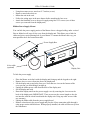
Mounting the Master
The Master comes ready to surface mount on the wall. However, you can also install the Master
in a standard 19" rack, recess the power supply into the wall or hide the power supply in the floor
or ceiling and hang only the display unit on the wall with optional hardware.
A qualified electrician who understands the electrical code in your area should install your Master.
The installation should not require any special tools, but may require extra hardware, wire, etc. as
required by your local electrical code.
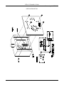
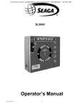
Surface Mount
Power Supply Box
Wall Mount Cover
Display Unit
3
LTRx-512 Installer’s Guide
To surface mount the Master
•
•
•
•
•
•
•
•
•
•
•
•
Place the Master on its back with the display unit facing up and the keypad to the right
Remove the two screws from just above the display unit
Lift the display unit up and away from you. Note that two rivets at the bottom of the
cover prevent you from lifting it straight up
Unplug the ribbon power cable from the back of the display unit
Set the display unit aside
Place two wall anchors and #8 screws 10 inches apart and level on the wall where you
want to mount the Master
If needed, place two wall anchors 5 inches below the first two screws
Hang the power supply onto the top two screws using the keyholes on the back
Screw two more #8 screws through the two holes at the bottom of the power supply into
the wall anchors
Follow the wiring steps in the next chapter
Reconnect the ribbon cable
Replace the display unit using the two screws that you earlier removed
Semi-Flush Mount
You can set the power supply portion of the Master into the wall. See the steps below and
refer to the Surface Mount drawing to semi-flush mount your Master. A competent electrician
should mount the Power Supply Box inside the wall
To recess the Master in the wall
•
•
•
•
•
•
•
•
•
•
•
Place the Master on its back with the display unit facing up and the keypad to the right
Remove the two screws from just above the display unit
Lift the display unit up and away from you. Note that two rivets at the bottom of the
cover prevent you from lifting it straight up
Unplug the ribbon power cable from the back of the display unit
Set the display unit aside
The power supply measures 12" wide x 6" high x 3 3/8" deep. The cover extends ½"
around the 12" x 6" dimensions. Cut a hole roughly 12¼" x 6¼" in the wall between two
studs where you want to hang your Master
Cut two blocks of wood for filler and attach them to the studs
Using the two holes on each side of the power supply, screw it to the blocks
Follow the wiring steps in the next chapter
Plug the ribbon cable
Replace the display unit using the two screws that you earlier removed
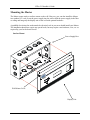
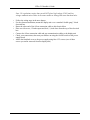
Lowering the Display Unit during Testing
With a Semi-Flush or Surface mount, you can hang the display unit below the back box when
testing the Master and its circuits. To lower the display unit, remove the two screws that
attach the display unit to the back box. Lift the unit up and away from the back box, leaving
4
LTRx-512 Installer’s Guide
the ribbon cable plugged in. For Semi-Flush mounts, remove the green communications plug
from the back of the display unit, so it can sit flat against the wall. Swing the two hooks on
the back of the unit up and hook them over the bottom edge of the back box. You can use the
keypad to turn on circuits or program the Master, as well as access the relay and connector
blocks inside the back box
D
D
5
LTRx-512 Installer’s Guide
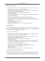
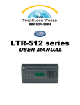
Rack Mount
The LTR8-512 and LTR8-512M come with two L-shaped brackets (optional on the
LTR4-512) so you can install your Master in a standard 19-inch rack
Power Supply Box
Brackets
Display Unit
To install the Master in a 19-inch rack
•
•
•
•
•
•
•
•
•
•
Place the Master on its back with the display unit facing up and the keypad to the right
Remove the two screws from just above the display unit
Lift the display unit up and away from you. Note that two rivets at the bottom of the
cover prevent you from lifting it straight up
Unplug the ribbon power cable from the back of the display unit
Set the display unit aside
Detach the display unit from the wall mount cover by removing the 4 screws on the back
of the display unit (IMPORTANT: These screws are the correct length so they do not
interfere with the circuit board inside the display unit. Using any other screws voids any
warranty)
Remove the rectangular knockout near the top of the power supply
Using the 4 screws that you removed from the display unit, attach the display unit to the
side of the power supply. You can fit a #1 Philips screwdriver with an 8 inch blade
through the holes opposite the 4 screw holes
Plug the ribbon cable from the power supply into the display unit
Remove the two screws from the side of the display unit
6
LTRx-512 Installer’s Guide
•
•
•
•
•
Using these same screws, attach an “L” bracket (or ear)
Repeat to attach the other ear
Mount the unit in the rack
Follow the wiring steps in the next chapter before attaching the box cover
Attach the furnished cover to the power supply using four 6-32 screws (two of these
screws you removed from the display unit)
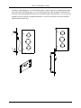
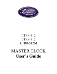
Hidden Power Supply Mount
You can hide the power supply portion of the Master above a dropped ceiling, under a raised
floor or behind a wall, up to 8 feet away from the display unit. This allows you to hide the
cables and gives a more pleasing look to your Master. To mount the Master this way, you
must purchase the 8-foot connection cable
Power Supply Box
8 foot cable
(optional)
Display Unit
To hide the power supply
•
•
•
•
•
•
•
•
Place the Master on its back with the display unit facing up and the keypad to the right
Remove the two screws from just above the display unit
Lift the display unit up and away from you. Note that two rivets at the bottom of the
cover prevent you from lifting it straight up
Unplug the ribbon power cable from the back of the display unit
Set the display unit aside
Detach the display unit from the power supply cover by removing the 4 screws on the
back of the display unit (IMPORTANT: These screws are the correct length so they do
not interfere with the circuit board inside the display unit. Using any other screws voids
any warranty)
Unplug the ribbon cable from the power supply board
Remove a knockout in the power supply and pass the 8-foot connection cable through it
using proper strain relief hardware. When properly installed, the cable will face away from
the transformer
7
LTRx-512 Installer’s Guide
Note: UL regulations require that you do NOT place high voltage (120V) and low
voltage communication cables in the same conduit or through the same knockout holes
•
•
•
•
•
•
•
Follow the wiring steps in the next chapter
For the cleanest installation, mount the display unit over a standard “double gang” 4-inch
electrical box
Route the other end of the 8-foot connection cable to this electrical box
Place two #8 screws, 12 inches apart and level, ½-inch down from the top of the electrical
box
Connect the 8-foot connection cable and any communication cables to the display unit
Check your connections, then turn your Master on using the On/Off switch on the power
supply board
Attach the furnished cover to the power supply using four 6-32 screws (two of these
screws you earlier removed from the display unit)
8
LTRx-512 Installer’s Guide
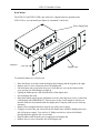
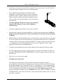
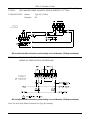
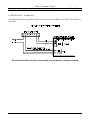
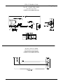
Wiring the Master
•
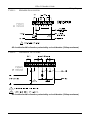
Wire the display panel and power relay units for bell control and clock synchronization. Refer
to the diagrams in Appendix D for more details. Until you complete this part of the wiring,
do not turn on the AC power to P4, and keep the power/relay unit’s toggle switch
turned “OFF” (Note: The LTR4-512 does not contain Terminal Block P3)
POWER SUPPLY
This is terminal block P4. See the
drawings below for a closeup of wiring
for 120VAC or 220/240VAC
TERMINAL BLOCK ‘P4’
WIRING THE LTR8-512
FOR 120VAC (nom.) OPERATION
J1 installed between 3 & 4 and J2
installed between 5 & 6
TERMINAL BLOCK ‘P4’
WIRING THE LTR8-512
FOR 220/240VAC (nom.) OPERATION
J1 installed between 4 & 5
9
LTRx-512 Installer’s Guide
•
Your Master is already setup for 120VAC operation. If you need to wire it for 220/240VAC,
change the jumper settings as shown in the drawings above
•
We recommend using stranded wire inside the Power
Supply Box. Stranded wire allows for a firm connection to
the Quick Connect terminals. Stranded wires are also less
likely to interfere with the relay board components. If you
must use solid wire, join the stranded wire to the solid wire
in another box
•
Note that applying 220/240 VAC power to a system not
setup for that voltage level can severely damage its
electronic parts
•
Attach the supplied quick-connects to the wires as needed
•
Plug the quick-connects into the terminal block, as shown in the drawings above. Failure to
properly connect the ground wire can increase interference and cause unsafe operating
conditions
•
While the Master is fused internally to protect its electronics, you must also fuse the incoming
AC line as required by your local electrical code. You should connect the unit to a dedicated
10 Amp circuit. You may need to add external MOV’s or diodes to sync a specific clock type
– see Appendix D for the wiring diagram of your type clock. Appendix C shows wiring
diagrams for bell circuits and communications
•
Complete any mounting steps in the previous chapter before turning on the power supply
•
Turn the toggle switch in the power supply to the “ON” position. The display may show the
message SYSTEM RECOVERY IN PROGRESS" for about 2 minutes, then you will see the
date and time
•
Fasten the cover to the power supply
EXTERNAL PULSE-SYNC
Your Master can synchronize to other systems if needed. For example, you have a
non-compatible time clock that the Master cannot synchronize, but it has a built-in bell ringer.
By shorting terminals 7 & 8 on terminal block P1, or terminals 6 & 7 of the communications
terminal on the back of the display unit, the Master will immediately reset to 00:00 (midnight).
If you can program the other device to close its circuit at 00:00 (Midnight) then the two
systems will remain reasonably in sync. WARNING: DO NOT APPLY POWER TO THESE
CONNECTIONS – only close the circuit for a short time (Duration must be at least 1, but not
more than 2 seconds)
10
LTRx-512 Installer’s Guide
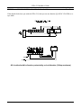
Setting up the Master
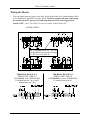
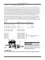
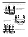
If you will use the Master to sync clocks, you must first use relays #7 & #8 (terminal block
P1) for synching. If you have an LTR8-512 or LTR8-512M and will use a second clock
type, you must use relays #5 & #6 (terminal block P2) for those clocks
Bell
Bell
Bell
Bell
Bell
Bell
Bell
Bell
Zone #1 Zone #2 Zone #3 Zone #4 Zone #5 Zone #6 Zone #7 Zone #8
Relay #1 Relay #2 Relay #3 Relay #4 Relay #5 Relay #6 Relay #7 Relay #8
---Clock Sync #2--- ---Clock Sync #1--Here are some suggested ways to program your Master’s relays:
1. Eight (8) bell zones that can last from 1 second to 99 seconds. Use this setup if your
Master will not synchronize secondary clocks.
2. Six (6) bell zones and one electro-mechanical wall clock sync control. Use this setup if
your Master will sync only one type of clock in one string.
3. Four (4) bell zones and two electro-mechanical wall clock sync controls. Use this setup if
you will synchronize two clock types, or if you have two strings of clocks (typically 20 to
35 clocks to a string).
The steps below lead you through getting the Master up and running.
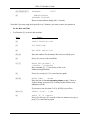
Enter your Password
•
The user password allows you to access user functions, but you must use the administrator
password to access advanced functions. You can change the user password, but you cannot
change the administrator password. To keep the administrator functions secure, only give this
guide to authorized personnel. You can learn more about user passwords in the User’s Guide.
All factory programmed passwords can be spelled out using the letters of a telephone keypad.
For example, the administrator password is 332537 or DEALER.
Enter the administrator password ‘332537’ [DEALER]
Press
Display
[#]
SELECT FUNCTION CODE
[0]
[0]=ENTER PASSWORD
[#]
PASSWORD:
000000
11
LTRx-512 Installer’s Guide
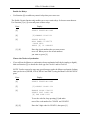
[3][3][2][5][3][7]
PASSWORD:
[#]
ADMINISTRATOR
PASSWORD ACCEPTED
Return to time and date display after 3 seconds
332537
Note that if you stop using the keypad for over 5 minutes, you must re-enter your password
Set the Date and Time
•
Use Function [1] to set the date and time
Press
Display
[#]
SELECT FUNCTION CODE
[1]
SET DATE/TIME
[#]
ENT.DATE: MM-DD-YYYY
[0]..[8]
Enter the numbers for the month, date and year (4-digit year)
[#]
Press [#] to move to the second line
[1]..[7]
ENTER DAY-OF-WEEK: D
1=SUNDAY..7=SATURDAY
Enter a number [1] - [7] for the day of the week,
Sunday through Saturday
[#]
Press [#] to accept (or [*] to cancel and try again)
[0]..[8]
ENTER TIME:
HH:MM
Enter the time of the next upcoming minute, using 12-hour or
24-hour format, then press [#]. (If using 24-hour format, enter
midnight as 00:00)
[0] or [1]
[#]
If you enter a time less than 13:00 (1:00 PM), you will see
SELECT [0]PM / [1]AM
PRESS [#] IF CORRECT
Press [#] at the top (‘00’ seconds) of the new minute to accept, or
press [*] to cancel and try again
12
LTRx-512 Installer’s Guide
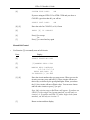
Enable the Relays
•
Use Function [6] to enable any control relays that you want to use
The Enable Circuits function only enables you to use certain relays. It does not turn them on.
Use Function [3] or [4] to actually turn on these relays
Press
Display
[#]
SELECT FUNCTION CODE
[6]
[6]=ENABLE CIRCUITS
[#]
SELECT ACTIVE
BELL ZONES 12345678
CLOCK CKTS
PRESS [#] IF CORRECT
[1]..[8]
Enter the circuit numbers that you want to turn
on or off. When you see the circuit numbers
you want on, press [#]
Choose the Clocks to Synchronize
•
If you will use the Master to synchronize electro-mechanical wall clocks (analog or digital),
then use Function [2] to choose the clock type for Clock #1 and/or Clock #2
NOTE: You do not need to enter any special setup to make the Master synchronize Lathem
time sync devices (DDC4R, LTR-0, DWA-S and OMC2) using the Master’s RS-485 SYNC
ports
Press
Display
[#]
SELECT FUNCTION CODE
[2]
[2]=SELECT CLOCK CTL
[#]
ENABLE CLOCK CIRCUIT
SELECT CLK1 CODE: NN
[#] FOR CODE LIST
To see the code list, keep pressing [#] and make
note of the code number for CLOCK1 and CLOCK2
[0]..[9]
Enter the 2-digit code for CLOCK1, then press [#]
13
LTRx-512 Installer’s Guide
[#]
SYSTEM TYPE CODE:
NN
If you are using an LTR8-512 or LTR8-512M and you chose a
CLOCK1 type other than 00, you will see
SELECT CLK2 CODE:
NN
[0]..[9]
Enter the code for CLOCK2, or 00, if none
[#]
PRESS [#] IF CORRECT
[#]
Press [#] to accept
-orPress [*] to cancel and try again
[*]
Manual Bell Control
•
Use Function [3] to manually turn on bell circuits
Press
Display
[#]
SELECT FUNCTION CODE
[3]
[3]=MANUAL BELL CTRL
[#]
MANUAL BELL CONTROLS
1-2-3-4-5-6-7-8
PRESS AND HOLD [#]
TO EXECUTE.[*]TO END
[1]..[8]
Enter the circuit numbers that you want to test. When you see the
circuits you want, press and hold [#]. Those circuits will turn on
their relays, as shown by the green panel lights. When you release
the [#], the circuits will turn off their relays. You can now choose
and test other circuits or press [*] to quit
Note: Only circuits setup as Bell Zones will appear. If you have an
LTR8-512 with a single clock system attached, you will only see
circuits 1-6. If you have an LTR4-512 with a single clock system
attached, you will only see circuits 1-2
[*]
Return to time and date display
14
LTRx-512 Installer’s Guide
Auto Test the Bells
Use the Auto Bell Test feature to turn on all bell relays once per minute at the start of each
minute. Once you start this function, you can test the continuity of your bell wiring circuits. Use
the “hidden code” 2355878 [BELLTST] to start the Auto Bell Test. When you enter this code,
ignore anything that displays on the screen
Use Function [6] to disable any relays that you do not want to use in your testing
Once you finish testing, make sure you enter the hidden code again to stop the Auto Bell Test and
use Function [6] to enable any relays that you earlier disabled
Set Daylight Savings
•
Your Master comes set to adjust for daylight savings in the United States. If you live outside
the United States or if your region does not observe daylight savings, use Function [7] to
change the country code
Press
Display
[#]
SELECT FUNCTION CODE
[7]
ENTER COUNTRY CODE
FOR DAYLIGHT SAVINGS
TIME ADJUSTMENT:
08
[0]..[9]
Enter your country code from Appendix C
[#]
Press [#] to accept (or [*] to cancel)
If your region does not observe daylight savings, then set your country code to 00
Setup Communications (LTR8-512 and LTR8-512M only)
•
Use Function [B] if you use the LTR MasterLink or Terminal Manager software with your
Master. You can setup your LTR8-512 with LTR MasterLink using RS-232 (serial), RS-485
(networked) or Modem (remote) Communications
You must enter these same settings for your LTR8-512 in the Terminal Manager or
LTR MasterLink software
15
LTRx-512 Installer’s Guide
You cannot choose function [B] directly. To enter Communications, press [#][9][0][0][#]
Press
Display
[#]
SELECT FUNCTION CODE
[9]
Press [9], then
[0][0]
Press [0] twice to see
[B]=COMMUNICATIONS
[#]
COMMUNICATIONS SETUP
SELECT BAUD RATE:
[2]400 -OR- [9]600
[2] or [9]
Enter [2] for 2400 baud or [9] for 9600 baud (9600 is the default)
9600 (or 2400) BAUD SELECTED
ENTER TERM ID#
000
Note: If the LTR8-512M will be programmed to call the NIST
Atomic clock, you must select 9600 Baud.
[0]..[9]
Enter a unique Terminal ID # from 001-127 (065 is the default)
[3]
PRESS [#] TO CONFIRM
[#]
Press [#] to accept
-orPress [*] to cancel and try again
[*]
Congratulations! You have finished the basic setup of your LTRx-512 Master. All of the Master
functions are described in the next section of this guide, such as setting up your bell schedules.
For detailed information, please refer to the User’s Guide.
The Master will exit itself out of Program Mode once you stop using the keypad for 5 minutes or
if you wish to exit programming mode immediately to prevent others from accessing the Master
Clock, simply enter an invalid password. (For example)
[#]
[0]
[#] 99 [#]
SELECT FUNCTION CODE
[0]=ENTER PASSWORD
PASSWORD:
16
99
LTRx-512 Installer’s Guide
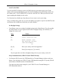
Functions Defined
[#]
[*]
Starts the Programming Functions and Confirms Entries
Ends Program functions and/or Cancels Entries (except the “Quick Check”)
Quick Check Commands
Quick Check commands display system information for about 2 seconds. You can press any of the
three quick check keys ([*], [1] or [3]) when the Master is in Clock Mode.
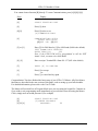
Quick Check Command [*] Status
Any time you see the time and date, you can press [*] to see the Master status. You will see the
firmware version, terminal ID#, communications baud rate, time display format (12-hr or 24-hr),
daylight savings country code and the clock types you have chosen
Quick Check Command [1] Edit Keys
Any time you see the time and date, you can press [1] to see the edit key descriptions. You can
use the edit keys to program Bell Schedules, Automatic Schedule Change Dates, and Holiday
Dates. When you press [1], you will see
[1] EDIT
[3] PRV
[4] DEL
[6] ADD
[9] 1ST
[#] NXT
[*] EXIT
Quick Check Command [3] 12/24 Hour Display
Any time you see the time and date, you can press [3] after entering your password to toggle the
time and date between 12-hour and 24-hour format. The 12-hour format shows AM or PM, while
the 24-hour format shows the day of the week (or ‘HO’ for Holiday).
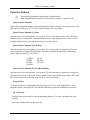
Program Keys
To access the Master’s programming functions, press the [#] key. As described below, some
functions require a user password, and advanced functions require the administrator password.
[0] = Password
You must enter a password for most programming functions. To enter your password, press
[#][0][#]
Enter your 6-digit password, then press [#]
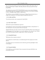
17
LTRx-512 Installer’s Guide
Once you enter your password, you can now program your Master until it detects that you
haven’t pressed a key for 5 minutes. After that, you must re-enter your password to keep
programming
The administrator password 332537 [DEALER] allows you to access advanced functions.
Functions that require the Administrator Password are [2] Select Clock Control, [6] Enable
Circuits, [7] Daylight Savings, and [B] Communications
The default user password is 000000. See Function [C] Change Password to learn how to
change your user password. You cannot change the administrator password
[1] = Set Date and Time
To set the date and time, enter your password, then [#][1][#]
[2] = Select Clock Control
This function requires the administrator password
Use this function to choose the clock makes and models that the Master will synchronize. To
start this function, enter your password, then press [#][2][#]
Appendix B lists the type codes. If you do not have the printed list handy, keep pressing [#] to
scroll through the list on the display. As you scroll, make note of the codes for both CLOCK1
and CLOCK2 (if needed). Enter the 2-digit code for CLOCK1, then press [#]
[3] = Manual Bell Control
This function does not require a password
Use this function to test bell circuits or to manually ring a bell. Press [#][3][#] to start this
function
You will know that your circuits have turned on when the green front panel lights for those
circuits light up
[4] = Program Schedules
Use this function to set bell schedules. Enter your password, then press [#][4][#] to start
programming schedules.
18
LTRx-512 Installer’s Guide
[5] = Schedule Changes
Use Schedule Changes to run schedules at a certain date and time. This function works much
like the Bell Schedule Function [4]. Enter your password, then press [#][5][#]. You can
program up to 16 changes at a time
[6] = Enable or Disable Circuits
This function requires the administrator password
Use this function to Enable and Disable bell relays during circuit wiring or maintenance. This
function can also ‘hold back’ clocks to manually adjust for daylight savings in the fall if you
do not use the Daylight Savings function [7]
Disabled relays will ignore any schedules, and you cannot manually turn them on
([3]=MANUAL BELL CTRL). After you complete and check your system wiring, use this
function to enable those circuits, so that they will turn on when called. Enter your password,
then press [#][6][#]
[7] = Daylight Savings Time
This function requires the administrator password
Your LTRx-512 knows the daylight savings time (DST) settings for over 75 countries. By using
the 2-digit “country code”, your LTRx-512 will automatically adjust for daylight savings time. If
your nation does not appear in the Country Code list, you can choose code ‘00’ and use
Lathem’s LTR MasterLink software to program when clock adjustments should occur
Enter your password, then press [#][7][#]
Enter your country code from the list in Appendix C or press [9] to see the list. Press [9] to
jump to each letter in the alphabet, then press [#] to scroll through the codes. (example: press
[9] to jump to 08: BAHAMAS, BERMUDA, press [9] again to jump to 08: CANADA, press
[9] again to jump to 02: DENMARK and so on). When you see your country code, enter it,
then press [#]
If your region does not observe daylight savings, then leave the country code at 00
[8] = Change Schedule
Use this function to override any active bell schedules that you setup in function
[5]=SCHEDULE CHANGES. Or, you can use this function to instantly run a schedule that you
19
LTRx-512 Installer’s Guide
setup in function [4]=PROGRAM SCHEDULE. Enter your password, then press [#][8][#] to
change a schedule
[9] = Sync Clocks
Use this function to quickly synchronize any secondary clocks. This function is primarily used
during initial installation or if power to your LTRx-512 stayed on while power to the secondary
clocks stopped.
Enter your password, then press [#][9][#]
[A] = Program Holidays
You can enter up to 16 dates as holidays in your LTRx-512. During holidays, only the events
that you set to occur on holidays will turn on when they reach the scheduled time
You cannot choose Function [A] directly. To start the Program Holidays function, enter your
password, then press [#][9][0][#]
[B] = Communications (LTR8-512 and LTR8-512M Only)
This function requires the administrator password
You cannot choose function [B] directly. To enter Communications, press [#][9][0][0][#]
You must enter these same settings for the Master in Lathem’s Terminal Manager or
LTR MasterLink software
[C] = Change Password
Use this function to change the default user password (000000) to a unique 6-digit number to
prevent unauthorized access to the LTRx-512’s programming functions. You should keep a
copy of this password in a safe place
You cannot choose function [C] directly. To start the Change Password function, enter
your current password, then press [#][9][0][0][0][#]
20
LTRx-512 Installer’s Guide
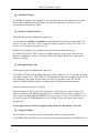
[D] = Time Calibration (Available with Firmware Version 5.02)
The Crystal Oscillator that provides the Time Base for the Master Clock is optimized for
operation at 25’ C / 75’F, where it will exhibit its highest accuracy. Due to natural aging of the
crystal and to installation of the Master Clock in locations that do not maintain close temperature
control, the frequency of the Time-Base is apt to drift from its calibrated value, causing some
deterioration in timekeeping accuracy. Use this function to calibrate the oscillator to achieve
maximum timekeeping accuracy within your environment.
You cannot choose function [D] directly. To start the Time Calibration function, enter the
Administrator Password, then press [#][9][0][0][0][0][#].
The following screen will be presented:
CALIBRATE TIME-BASE
SELECT: 0 = NORMAL * Note: ‘*’ indicates initial mode
1 = FASTER
2 = SLOWER
To set the Oscillator to the factory default frequency, press [0]. The display will show:
TIME-BASE NORMAL
SELECT: 0 = NORMAL *
1 = FASTER
2 = SLOWER
If the Master Clock has been running ‘slow”, you can make the oscillator run faster by pressing
[1]. You may repeatedly press [1] to increase the adjustment. The display will show the following,
where ‘NN’ is the amount of positive adjustment applied: Each positive step represents a
correction of approx. 10.7 seconds / month. With a maximum adjustment of +31 steps, this
represents correction of up to +5.5 minutes / month.
TIME-BASE FASTER +NN
SELECT: 0 = NORMAL *
1 = FASTER
2 = SLOWER
If the Master Clock has been running ‘fast”, you can make the oscillator run slower by pressing
[2]. You may repeatedly press [2] to increase the adjustment. The display will show the following,
where ‘NN’ is the amount of negative adjustment applied: Each negative step represents a
correction of approx. -5.35 seconds / month. With a maximum adjustment of -31 steps, this
represents correction of up to -2.75 min. / month.
TIME-BASE SLOWER -NN
SELECT: 0 = NORMAL *
21
LTRx-512 Installer’s Guide
1 = FASTER
2 = SLOWER
To exit the Time-Base Calibration procedure, press either [#] or [*].
EXAMPLE: During installation, set the Master Clock’s time to match an accurate reference
(Cell Phone display, Computer Network Time, WWVB Radio Clock, etc.). At the end of
one month, compare the Master’s time against the Reference Time, to determine accuracy.
If the Master were, say, 32 seconds slow, then calculate required positive correction as 32
/ 10.7 = 2.99 ~ 3. Set the correction to “FASTER + 03”.
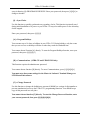
Auto Bell Test
No password is required for this function
Use the Auto Bell Test feature to turn on all bell relays once per minute at the start of each
minute. Once you start this function, you can test the continuity of your bell wiring circuits. Use
the “hidden code” 2355878 [BELLTST] to start the Auto Bell Test. While entering this code,
ignore anything that displays on the screen
Use Function [6] to disable any relays that you do not want to use in your testing
Once you finish testing, make sure you re-enter the hidden code to stop the Auto Bell Test and
use Function [6] to enable any relays that you earlier disabled
22
LTRx-512 Installer’s Guide
Daylight Savings Codes
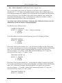
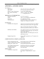
APPENDIX A - SPECIFICATIONS
ELECTRICAL:
Input Voltage
Input Power
Memory / Quartz Time Backup
Bell / Clock Control Relays
Fuse
MECHANICAL / ENVIRONMENTAL:
Operating Temperature
Weight
Dimensions
Mounting Options
FUNCTIONAL:
Secondary Clocks Supported
120 or 220 / 240 VAC @ 60Hz or 50Hz
50 VA max (less than 0.5A @ 120V)
10 year (nom.) Lithium Battery
120VAC / 28VDC, 10A , Pluggable
1 x 1.0 Amp Main (AGC1)
32°-175° F (0°-80° C)
About 12 lb. (depending on configuration)
See configuration drawings
Semi-Flush, Surface, 19" Rack, Hidden Power
Supply (some configurations optional)
Any two (2) of twenty-four (24) types plus Lathem
DDC4R synchronization built-in; See Appendix B.
One (1) of twenty-four (24) types plus Lathem
DDC4R synchronization built-in; on the LTR4-512
Bell Zones and Schedules
Up to eight (8) zones [less two (2) for each electromechanical secondary clock type]. {Up to four (4)
zones on the LTR4-512.}
Eight (8) Schedules, each allowing sixty-four (64)
multi-function events.
Daylight Savings Time
Supports DST standards for over 75 countries. See
Appendix C.
COMMUNICATIONS: (LTR8-512 and LTR8-512M)
Remote Communications with
RS-232 point-to-point @ 2400/9600 Baud
Lathem LTR MasterLink, Terminal RS-485 multi-drop network
Manager and “Atomic Clock”
Internal modem (option) dial-in / dial-out
Clock / Master Synchronization
using DDC4R Protocols
or Midnight Impulse
REGULATORY:
Certifications / Registrations
RS-485 Sync-In/Out Port @ 9600 Baud
RS-485 Sync-Out Port @ 9600 Baud
Dry-contact input
FCC Part15-ClassB, UL, cUL, CE
FCC Part 68 / Canada ICES-003 - Class B
CE
23
LTRx-512 Installer’s Guide
Daylight Savings Codes
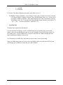
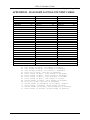
APPENDIX B – DAYLIGHT SAVINGS COUNTRY CODES
ALBANIA
ANDORRA
ARMENIA
AUSTRIA
AZERBJAN
AZORES
BAHAMAS
BALEARIC ISLANDS
BELARUS
BELGIUM
BERMUDA
BOSNIA/HERCGVENA
BRAZIL
BULGARIA
CANADA
CHANNEL ISLANDS
CHILE
CROATIA
CUBA
CYPRUS
CZECH REP
DENMARK
EASTER ISLAND
EGYPT
02
02
02
02
02
02
08
02
02
02
08
02
13
02
08
01
12
02
06
02
02
02
02
09
ENGLAND
ESTONIA
FALKLAND ISLANDS
FINLAND
FRANCE
GERMANY
GIBRALTER
GREECE
GREENLAND
HAITI
HUNGARY
IRAN
IRAQ
IRELAND
ISRAEL
ITALY
JAMAICA
JORDAN
KAZAKHSTAN
KURGYZSTAN
LATVIA
LEBANON
LIECHTENSTEIN
LUXUMBOURG
01
02
10
02
02
02
02
02
07
07
02
02
03
02
04
02
08
05
02
02
02
02
02
02
USER-SPEC. DATES
00
UNDEFINED
14
01
02
02
03
04
05
06
07
08
09
10
11
12
13
MALTA
MONACO
NETHERLANDS
NEW ZEALAND
NORWAY
POLAND
PORTUGAL
ROMANIA
RUSSIA
SAN MARINO
SCOTLAND
SLOVAKIA
SLOVENIA
SPAIN
SWEDEN
SWITZERLAND
SYRIA
TURKEY
UKRAINE
UNITED KINGDOM
UNITED STATES
VATICAN CITY
YUGOSLAVIA FED.
Last Sunday in March, 3rd Sunday in October
Last Sunday in March, last Sunday in September
Last Sunday in March, last Sunday in September
First day of April, Last day of September
First Friday in April, First Sunday in September
First Friday in April, third Friday in September
First Sunday in April, First Saturday in October
First Sunday in April, Last Sunday in October
Second Sunday in March, First Sunday in November
First day of May, Last day of September
Second Sunday in September, Third Sunday of March
First Sunday of October, Third Sunday of March
Second Sunday of October, Second Saturday of February
Third Sunday of October, Second Sunday of February
24
02
02
02
11
02
02
02
02
02
02
02
02
02
02
02
02
03
02
02
02
08
02
02
LTRx-512 Installer’s Guide
Secondary Clock Types
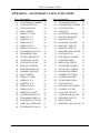
APPENDIX C - SECONDARY CLOCK TYPE CODES
Type Description
01
01
01
01
01
01
01
01
01
01
01
01
02
02
02
02
02
02
02
02
02
02
02
02
02
02
02
03
03
04
SYNCHRONOUS WIRED
LATHEM TYPE SS
CINCINNATI D10
IBM 77 SERIES
SIMPLEX 77 SER
SIMPLEX 93-9
SIMPLEX 91-9
SIMPLEX 941-9
SIMPLEX 943-9
SIMPLEX 6310-9231
STANDARD EL D10,D12
STROMBERG 3000
3W MIN IMPULSE/59
LATHEM ISC 2W/3W
CINCINNATI D2-D4
DUKANE 24 SERIES
EDWARDS IMPULSE
FARADAY IMPULSE
IBM 75 SERIES
SIMPLEX 74 SER
SIMPLEX 91-4
SIMPLEX 93-4
SIMPLEX 941-4
SIMPLEX 943-4
SIMPLEX 6310-9075
STANDARD IMPULSE
STROMBERG IMPULS
STANDARD EL SYNCH
AMR T&S X55BHGA801
STANDARD TM AR-2A
Type Description
Page
26
26
26
26
26
26
26
26
26
26
26
26
26
26
26
26
26
26
26
26
26
26
26
26
26
26
26
27
27
28
05
06
06
06
06
07
07
08
09
10
11
12
14
15
16
17
18
18
19
19
20
21
22
23
23
23
24
25
27
25
3W MIN IMPULSE/58
SYNCHRONOUS WIRED
CINCINNATI D8
FARADAY
HONEYWELL ST402A
DUKANE 24F200 DIG
DUKANE 24F750
RAULAND 2410 DIG
SIMPLEX 2 MTR /59
SIMPLEX 2 MTR /45
EDWARDS DUAL MOTR
CINCINNATI D6
ELECTRONIC CODED
STRAIGHT FREQ.
IMPLS 12HR COR/59
STANDARD TM AR2/3
NATNL SYNC WIRED
DUKANE 240 SERIES
STMBRG SYN WIR/56
LATHEM SS MODIF.
3W MIN IMPULSE/44
CINCINNATI D1
DUKANE SYNC WIRED
CONDOR 2412 DIG
RAULAND 2422 DIG
CONDOR BAR-AC-4412
EDWARDS SYNC E-1
SPECIAL TEST
SIMPLEX 2310 DUAL MT
Page
28
29
29
29
29
28
30
30
30
31
31
32
33
34
35
36
36
36
36
37
37
38
38
39
40
41
30
LTRx-512 Installer’s Guide
Wiring Diagrams
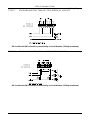
WIRING SECONDARY CLOCKS
TYPE 01 -
SYNCHRONOUS WIRED
TYPES INCLUDE:
Lathem
Cincinnati
IBM
Simplex
Stromberg
Type SS Wall Clocks
D10 (115VAC), D12 (24VAC)
77 Series
77 Series, 93-9, 91-9, 941-9, 943-9, 6310-9231
3000
All circuits should be fused or protected by a circuit breaker (10Amp maximum)
TYPE 02 -
THREE WIRE MINUTE IMPULSE (59TH MIN.)
TYPES INCLUDE:
Lathem
Cincinnati
Edwards
Faraday
IBM
Simplex
Standard
Stromberg
Type ISC (3-Wire)
D2, D4
Impulse
Impulse
75 Series
74 Series, 91-4, 93-4, 941-4, 943-4, 6310-9075, 6310-9231
Impulse
Impulse
All circuits should be fused or protected by a circuit breaker (10Amp maximum)
26
LTRx-512 Installer’s Guide
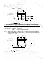
TYPE 02 -
TWO WIRE REVERSE POLARITY MINUTE IMPULSE (59
TYPES INCLUDE:
Lathem
Cincinnati
TH
Wiring Diagrams
MIN.)
Type ISC (2-Wire)
D3
All circuits should be fused or protected by a circuit breaker (10Amp maximum)
TYPE 03 -
STANDARD ELECTRIC SYNCHRONOUS (*Old Style: Dual Motor)
AMERICAN TIME & SIGNAL #X55BHGA801
All circuits should be fused or protected by a circuit breaker (10Amp maximum)
Note: For New Style (Motor+Solenoid), see Type 06 (Faraday)
27
LTRx-512 Installer’s Guide
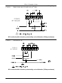
TYPE 04 -
Wiring Diagrams
STANDARD ELECTRIC TIME AR-2A TWO WIRE DUAL VOLTAGE
All circuits should be fused or protected by a circuit breaker (10Amp maximum)
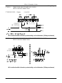
TYPE 05 -
THREE WIRE MINUTE IMPULSE (58TH MIN.)
All circuits should be fused or protected by a circuit breaker (10Amp maximum)
28
LTRx-512 Installer’s Guide
Wiring Diagrams
TYPE 06 -
SYNCHRONOUS WIRED
TYPES INCLUDE:
Cincinnati
Faraday
Honeywell
D8
(New Style: Motor + Solenoid)
ST402A
All circuits should be fused or protected by a circuit breaker (10Amp maximum)
TYPE 07 -
DUKANE 24F200 DIGITAL CLOCKS
NOTE: THIS SELECTION IS NOT SUPPORTED ON THE LATHEM LTR8-512 OR
LTR4-512 SERIES. CORRECTION FOR DUKANE 24F200 DIGITAL CLOCKS IS
AVAILABLE ON THE DUKANE 24A715 SERIES MASTER CONTROL WITH SOLIDSTATE RELAYS. CONTACT DUKANE CORPORATION OR YOUR DUKANE
VENDOR.
All circuits should be fused or protected by a circuit breaker (10Amp maximum)
29
LTRx-512 Installer’s Guide
Wiring Diagrams
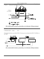
TYPE 08 -
RAULAND 2410 DIGITAL CLOCKS (24VAC and 115VAC)
115VAC TYPE
All circuits should be fused or protected by a circuit breaker (10Amp maximum)
24VAC TYPE
All circuits should be fused or protected by a circuit breaker (10Amp maximum)
TYPE 09 -
SIMPLEX 59TH MINUTE DUAL MOTOR
TYPE 10 -
SIMPLEX 45TH MINUTE DUAL MOTOR
TYPE 27 -
SIMPLEX 2310 DUAL MOTOR
Same hourly corrections as Type 09, but with addition of 12-hour corrections, as for
Type 03.
All circuits should be fused or protected by a circuit breaker (10Amp maximum)
30
LTRx-512 Installer’s Guide
Wiring Diagrams
TYPE 11 -
EDWARDS DUAL MOTOR
All circuits should be fused or protected by a circuit breaker (10Amp maximum)
TYPE 12 -
CINCINNATI ‘D6’ CLOCKS
All circuits should be fused or protected by a circuit breaker (10Amp maximum)
31
LTRx-512 Installer’s Guide
Wiring Diagrams
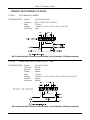
TYPE 14
-
ELECTRONIC CODED CLOCKS
Clocks run normally with 120 VAC power. For any bells or clock correction, the generator prestart
relay (SK1) first turns on for the signal-generator to reach frequency. SK1 turns on at the 00 second
after a programmed time or manual bell time. Then relay SK2 turns on for 3 seconds, from the 10th to
the 13th second, to apply the generator signal (coded cup start signal) onto the 120 VAC. Bell circuits
then turn on for 3 seconds, in the order listed below, applying the generator signal onto the 120 VAC
for decoding by the coded cups. The bell relay contacts must connect in parallel with the normally open
contacts of relay SK2. If it is not time for a clock correction signal, then SK1 turns off at the 59th
second. At the 57th minute of each hour, SK2 turns on from 57:54 to 58:02, applying the 8-second
hourly correction generator signal onto the 120 VAC. At 5:57 AM and 5:57 PM (12-hr correction),
SK2 turns on from 5:57:54 to 5:57:08, applying a 14-second 12-hour correction generator signal onto
the 120 VAC. For daylight savings, the clocks advance to the proper time by normal 12-hour
correction, not at 2:00 AM. The order of each relay operation is listed below (see NOTE for Type 15
re: SK1):
RELAY
SK1 Gen. Prestart (hourly corr.)
SK2 Start Signal (hourly corr.)
FROM
H:57:00
H:57:10
TO
FROM
H:57:13
H:57:54
TO
H:59:00
H:58:02
SK1 Gen. Prestart (12-hour corr.)
SK2 Start Signal (12 hour corr.)
H:57:00
5:57:10
5:57:54
H:59:00
5:58:08
SK1 Gen. Prestart (bells)
SK2 Start Signal (bells)
H:MM:00 H:MM:59
H:MM:10 H:MM:13
Bell Circuit 6
Bell Circuit 5
Bell Circuit 4
Bell Circuit 3
Bell Circuit 2
Bell Circuit 1
H:MM:20
H:MM:25
H:MM:30
H:MM:35
H:MM:40
H:MM:45
5:57:13
H:MM:23
H:MM:28
H:MM:33
H:MM:38
H:MM:43
H:MM:48
Bells should not be scheduled for:
HH:58:SS
For Masters including firmware versions
prior to V2.17 only:
NOTE: The LTRx-512 was designed for
clocks that do not require a generator prestart to set the frequency level. Clocks
using this pre-start may not work with the
LTRx-512 older than V2.17
All circuits should be fused or protected by a circuit breaker (10Amp maximum)
32
LTRx-512 Installer’s Guide
Wiring Diagrams
TYPE 15 -
STRAIGHT FREQUENCY
Clock correction and bell circuit operations are generated by sequentially applying various frequencies
onto the 120 VAC. Each bell and clock correction circuit has its own frequency. Each bell and clock
correction circuit has a receiver circuit that applies the associated bell or clock frequency (3510 Hz
normally used for clock signals). For daylight savings, the clocks advance to the proper time by normal
12-hour correction, not at 2:00 AM. The time sequence of applying the frequencies to the 120 VAC is
shown below, and the Master’s bell and system relays control these frequencies:
RELAY
FROM
Bell Ckt. 1
Bell Ckt. 2
Bell Ckt. 3
Bell Ckt. 4
Bell Ckt. 5
Bell Ckt. 6
H:MM:00
H:MM:05
H:MM:10
H:MM:15
H:MM:20
H:MM:25
SK2
(Hourly Correction)
(12-Hour Correction)
SK1
(Hourly Correction &
12-HourCorrection)
(Bells)
H:57:54
5:57:54
TO
H:MM:05
H:MM:10
H:MM:15
H:MM:20
H:MM:25
H:MM:30
Bells should not be
scheduled for:
HH:58:SS
or
00:00:SS
H:58:02
5:58:08
H:57:00
H:59:00
35 sec of min
30 sec of
previous to
Bell time
Bell
NOTE: Bells must be programmed 1 minute ahead of desired time.
Bells will not work during manual clock corrections and at the 58th minute.
For Masters including firmware
versions prior to V2.17 only:
NOTE: The LTRx-512 was designed
to work with clocks that do not
require a generator pre-start to set the
frequency level. Clocks using this prestart may not work with the LTRx512 firmware older than V2.17.
All circuits should be fused or protected by a circuit breaker (10Amp maximum)
33
LTRx-512 Installer’s Guide
Wiring Diagrams
TYPE 16 -
THREE WIRE MINUTE IMPULSE (59 MIN)
WITH 12-HOUR CORRECTION
TYPES INCLUDE:
Simplex
91 and 941
All circuits should be fused or protected by a circuit breaker (10Amp maximum)
TYPE 16 -
TWO WIRE REVERSE POLARITY MINUTE IMPULSE (59 MIN)
WITH 12-HOUR CORRECTION
24 V
All circuits should be fused or protected by a circuit breaker (10Amp maximum)
34
LTRx-512 Installer’s Guide
TYPE 17 -
Wiring Diagrams
STANDARD ELECTRIC TIME AR-2 TWO WIRE DUAL VOLTAGE
All circuits should be fused or protected by a circuit breaker (10Amp maximum)
TYPE 17 -
STANDARD ELECTRIC TIME AR-3 THREE-WIRE IMPULSE
All circuits should be fused or protected by a circuit breaker (10Amp maximum)
35
LTRx-512 Installer’s Guide
Wiring Diagrams
TYPE 18 -
NATIONAL SYNCHRONOUS WIRED
TYPES INCLUDE:
Dukane
Rauland
240 Series
2463 Series
All circuits should be fused or protected by a circuit breaker (10Amp maximum)
TYPE 19 -
STROMBERG SYNCHRONOUS WIRED
TYPES INCLUDE:
NOTE:
Stromberg
Lathem
Synchronous
Type SS Wall Clocks (modified)
Lathem type SS wall clocks can run according to the above signal operation if modified to
reference the minute and second hands to HH:57:16 (versus HH:59:00) and the hour hand to
12 o'clock versus 6 o'clock.
All circuits should be fused or protected by a circuit breaker (10Amp maximum)
36
LTRx-512 Installer’s Guide
Wiring Diagrams
TYPE 20 -
THREE WIRE MINUTE IMPULSE (44
TH
MIN.)
All circuits should be fused or protected by a circuit breaker (10Amp maximum)
TYPE 21 -
CINCINNATI ‘D1’
All circuits should be fused or protected by a circuit breaker (10Amp maximum)
37
LTRx-512 Installer’s Guide
Wiring Diagrams
TYPE 22 -
DUKANE SYNCHRONOUS WIRED
All circuits should be fused or protected by a circuit breaker (10Amp maximum)
TYPE 23 -
CONDOR DIGITAL CLOCKS (Model 2412)
TYPES INCLUDE:
Condor
2412
If the digital clocks lose sync with the LTRx-512, then you can use function [9]=SYNC CLOCKS to resync them.
All circuits should be fused or protected by a circuit breaker (10Amp maximum)
38
LTRx-512 Installer’s Guide
Wiring Diagrams
TYPE 23 -
CONDOR DIGITAL CLOCKS (Model 2422)
TYPES INCLUDE:
Rauland 2422
If the digital clocks lose sync with the LTRx-512, then you can use function [9]=SYNC CLOCKS to resync them.
All circuits should be fused or protected by a circuit breaker (10Amp maximum)
39
LTRx-512 Installer’s Guide
Wiring Diagrams
TYPE 23 -
CONDOR DIGITAL CLOCKS (BAR-AC-4412)
If the digital clocks lose sync with the LTRx-512, then you can use function [9]=SYNC CLOCKS to resync them.
All circuits should be fused or protected by a circuit breaker (10Amp maximum)
40
LTRx-512 Installer’s Guide
Wiring Diagrams
TYPE 24 -
EDWARDS SYNCHRONOUS WIRED CLOCKS - TYPE E1
All circuits should be fused or protected by a circuit breaker (10Amp maximum)
41
LTRx-512 Installer’s Guide
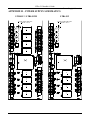
Wiring Diagrams
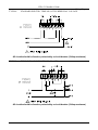
APPENDIX D - WIRING DIAGRAMS
Fig. D1 - TERMINAL BLOCK ‘P4’
WIRING THE LTRx-512 FOR 120VAC (nom.) OPERATION
2
1
BLK
GRN
WHT
120 VAC
3
4
5
J1
6
7
8
J2
All circuits should be fused or protected by a circuit breaker (10Amp maximum)
WIRING THE LTRx-512 FOR 220/240VAC (nom.) OPERATION
1
2
BLK
GRN
WHT
220/240 VAC
3
4
5
6
7
8
J1
All circuits should be fused or protected by a circuit breaker (10Amp maximum)
42
LTRx-512 Installer’s Guide
Wiring Diagrams
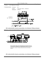
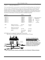
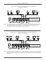
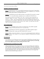
Fig. D2 - TYPICAL SIGNAL DEVICE WIRING
All circuits should be fused or protected by a circuit breaker (10Amp maximum)
CKT 7A & 7B Operate Together. You may use
& 7Bfor
Operate
Together.
You
either of CKT
these 7A
circuits
bells. In
LTR4, these
may
use
either
of
these
circuits
for
bells.
circuits become CKT 3 and CKT 4.
Voltage IN
1
2
4
3
5
7
6
8
P1
Zone
8
CKT 8
Zone
7A
CKT 7A
Zone 7B
CKT 7B
Zone 7A & 7B Operate Together
CKT 7A & 7B Operate Together
Voltage IN
CKT
& 5B
Operate
Together.
CKT
5A 5A
& 5B
Operate
Together.
YouYou
may
useofeither
these for
circuits
usemay
either
these of
circuits
bells.for
In
bells.
LTR4,
these circuits become CKT 1 and
CKT 2.
1
2
3
4
5
6
7
8
P2
Zone
CKT 66
Zone
5A
CKT 5A
Zone
5B
CKT 5B
Zone
CKT 5A
5A && 5B
5B Operate
OperateTogether
Together
Voltage IN
P3 is notZone
included
thenot
LTR4-512.
Usethe
CKT
5, 6, 7,
1 – 4inare
included in
LTR4-512.
& 8 for Bell
Use Circuits.
Zones 5,6,7, & 8 for Bell Circuits.
1
2
3
4
5
6
7
8
P3
Zone 1
CKT 4
Zone 2
CKT 3
Zone 3
CKT 2
Zone 4
CKT 1
43
LTRx-512 Installer’s Guide
Wiring Diagrams
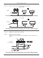
Fig. D3 - COMPUTER CABLE
(For Front Access Port)
(LTR8-512 and LTR8-512M Only)
Fig. D4 - RS-232 CABLE
(for permanent connection to the
Communications Terminal Block)
(LTR8-512 and LTR8-512M Only)
44
LTRx-512 Installer’s Guide
Wiring Diagrams
Fig. D5 - SYNCHING UP TO 60 RS-485 TIME SYNC DEVICES
WITHOUT A BUFFER
RS-485
DSD
+ -
RS-485
DSD
+ -
RS-485
DSD
+ -
RS-485
DSD
+ -
1
2
3
TxD
G
N
D
RxD
MODEM
RS-232
4
5
D
D
+
RS-485
6
7
8
G
N
D
S
Y
N
C
D
D
D
D
+
+
SYNC
SYNC
OUT
IN
RS-485
DATA SYNC
PULSE
SYNC
HOST COMMUNICATIONS
LTR8-512 & LTR8-512M Only
RS-485
DSD
+ -
RS-485
DSD
+ -
9 10 11 12 13
~~
~
Ports are located on the
back of the Display Unit
12V~
AC
OUT
250ma
Notes: Up to 30 RS-485 Data Sync Devices (DSDs) can be connected to the Data Sync port. Since the SYNC IN
port can send as well as receive, 30 extra devices can be connected. If more than 60 DSDs are to be
connected, another Master Clock will have to be used as a “Booster”.
Fig. D6 - LTRx-512 USED AS SLAVE TO ALLOW 30 EXTRA RS-485
TIME SYNC DEVICES
RS-485
DSD
+ -
RS-485
DSD
+ -
MODEM
1
2
3
TxD
G
N
D
RxD
RS-232
4
5
6
7
8
D
D
+
RS-485
G
N
D
S
Y
N
C
D
D
D
D
+
+
SYNC
SYNC
OUT
IN
RS-485
DATA SYNC
HOST COMMUNICATIONS
LTR8-512 & LTR8-512M Only
Note:
RS-485
DSD
+ -
RS-485
DSD
+ -
PULSE
SYNC
RS-485
DSD
+ -
MASTER
CLOCK
+ -
9 10 11 12 13
~
~
12V~
AC
OUT
250ma
Ports are located on the
back of the Display Unit
Since the Sync In port can send as well as receive, 30 extra devices can connect here. If you already have a
Master Source, such as an LTR-0, connect it and its string of clocks to the Sync In port, for a total of up to
60 devices.
45
LTRx-512 Installer’s Guide
Wiring Diagrams
Fig. D7 – COMMUNICATION TERMINAL BLOCK
Rear of Display Unit
NOTES:
1. Twisted-pair (Cat-3/Cat-5) wire connects directly to Terminal Block; up to 2 wires per position
2. Pulse-sync input is same as provided in power supply. One (1) second (min.) dry-contact switch
closure across terminals causes Master to reset time to 12:00AM of nearest date
3. Grounds (GND) are “signal grounds”, not “chassis grounds”
4. Load on non-regulated 12VAC output must be less than 250mA
5. For DDC4R communications, the LTRx-512 automatically sets itself as a master or slave
Strain Relief for the Communications Cable
•
Using the two wire tie wraps included in the
installation kit, attach them to the terminal block
as shown in this sample to provide strain relief to
the communications cable. Use any two empty
positions.
46
LTRx-512 Installer’s Guide
Wiring Diagrams
Use the six (6) connections as follows:
RS-485 Sync Time Device Connection
•
Sync In: Terminal block pair used to receive RS-485 synchronization from another Lathem Master
product or radio sync device, or transmit the LTRx-512’s own sync commands to up to 31 RS-485
devices, including Lathem Masters and DDC4R Wall Clocks
•
Sync Out: Terminal block pair used to buffer and repeat a received RS-485 sync signal, or transmit
the LTRx-512’s own synchronization commands to up to an additional 31 RS-485 devices
Note: When first powered on, the LTRx-512 will “listen” to the Sync-In line to determine if it
should be a “Master” or a “Slave”. If it does not receive a time update for 15 minutes, it will
assume it is a “Master” and start transmitting the time signal on the RS485 Synchronization line,
every minute. It will re-evaluate it’s Master/Slave status every day at 00:00 Hours. When setting up
the Master/Slave system, make sure that you power on the “Master” first and connect the other
LTRx-512 to the Sync-Out port on that clock.
Host Communications
•
RS-232: Three terminal block contacts for RS-232 communications with an IBM-compatible
computer running LTR MasterLink software for easy system setup
•
RS-485: Terminal block pair for RS-485 communications with an IBM-compatible computer
running LTR MasterLink software and SWIFT (RS485-RS232 converter)
•
Modem: Modular connector for modem use. You can use the optional internal modem to dial out to
the “Atomic Clock” at Ft. Collins, CO, or for a remote site using the LTR MasterLink and Terminal
Manager software
12 Volt AC Out
•
A non-regulated 12 Volt 250ma power source. Used with the LTR-RSS Remote Schedule Selector
when in close proximaty to the Master Clock. This circuit is not fused seperately and attaching
devices with a higher current load may damage the Master Clock.
Mounting the Master with Hidden Power Supply
•
Using the optional eight (8) foot Connection Cable, you can mount the Display Unit semi-flush on
the wall and place the Power Supply Box in the ceiling, floor or behind a wall. When attaching this
cable, remove the standard short cable and connect the 8 foot cable to the power supply board with
the cable moving away from the circuit board. Connect the other end to the back of the Display Unit
using the ribbon cable connector. The cable should lead towards the bottom of the Display Unit.
Attach the strain releif cable clamps at each end.
47
LTRx-512 Installer’s Guide
Wiring Diagrams
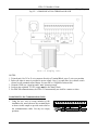
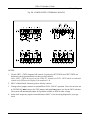
Fig. D8 - POWER SUPPLY TERMINAL BLOCKS
NOTES:
1. Circuits CKT1...CKT4 designate bell controls. Circuit pairs CKT5/CKT6 and CKT7/CKT8 can
function as clock synchronization circuits or as bell controls
(Note: CKT1…CKT4 do not exist on the LTR4-512. Instead use CKT5…CKT8 which are indicated
related to the LEDs on the Display Unit numbered 1-4).
2. MOV’s (Metal-Oxide Varistors) protect all relay contacts
3. Voltage-select jumpers connect to terminal block P4 for 120VAC operation. Users who need to run
at 220/240VAC must remove the 120V jumpers and install one jumper wire for the 240V selection.
The system will automatically adjust for operation at 60Hz or 50Hz at either voltage
4. Some clock setups may require external diodes or MOV’s. See the wiring diagram for your type
clock
48
LTRx-512 Installer’s Guide
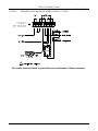
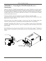
Installing the Modem
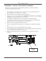
APPENDIX E – INSTALL THE OPTIONAL MODEM
Installation of the optional internal modem should be performed by a trained and competent
electronics technician. Follow these steps;
1.
Turn off the power to the Master Clock. You can either access the on/off switch inside the
Power Supply Box or turn off the power at the source.
2.
Remove the four (4) screws from the sides of the Display Unit.
3.
Gently remove the cover of the Display Unit. Some adhesive me hold the cover to the display
and keypad. A gentle pull should have the cover pull free.
4.
Locate the large rectangular hole in the circuit board just to the right of the display.
5.
Carefully insert the modem into the sockets on each side of the opening. The modem goes in
with the transformer on the modem board at the top of the board.
6.
Replace the cover and secure it with the four (4) screws.
7.
Connect a working ANALOG telephone line to the telephone jack on the back of the display
unit.
8.
Replace the Master Clock to its original position and restore power.
9.
Setup the Communications on the Master Clock. Press [#][9][0][0][#] and ensure that the baud
rate is at 9600 and verify the ID# of this Master Clock.
10. Setup your LTR MasterLink software to communicate with a modem clock and test the
connection.
1
2
3
4
5
6
7
8
0
9
#
*
MODEM
Installed
49
LTRx-512 Installer’s Guide
Connecting the LTR-RSS
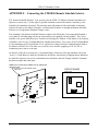
APPENDIX F – Connecting the LTR-RSS Remote Schedule Selector
The “Remote Schedule Selector” is an accessory for the LTR8-512 Master Controller and allows an
Operator to select one (1) of the eight (8) possible schedules stored in the Master Controller [or No
Schedule] for immediate activation. The selection made will remain in effect until either an alternate
selection is made (at the Master’s KeyPad, via MasterLink Software or through the Remote Schedule
Selector) or a Programmed Schedule Change occurs.
The Assembly of the Remote Schedule Selector consists of an Electronic Circuit suspended beneath a
cover plate for a double-gang switch-type electrical box (not supplied with the product). The Circuit
includes a low-power MicroProcessor, a method of selecting the ‘Address’ of the Master to be remotely
controlled, and a 4-screw Terminal Block for Installer Interconnect. Two screws of the Terminal Block
are for attachment of the Twisted-Pair (Cat-3 typical) low-voltage Network Communications Cable to
the Master’s RS-485 Port. The other two screws are to be used for supplying 9-24V AC/DC as
continuous power source to the unit.
On the face of the the cover plate are a 10-position Rotary Switch (to select the Schedule to be made
‘Active’), a Push Button to send the Command to the Master, and an array of lighting Status Indicators
by which the Operator can receive confirmation from the Master that the Change Schedule Command
has been accepted and acted upon.
MASTER CONTROL REMOTE SCHEDULE
SELECTOR
COVER PLATE FOR DOUBLE-GANG
CIRCUIT BOARD
LAYOUT
WALL BOX
DD+
~
~
1 2 3 4 5 6 7 8
B
A
U
50
64
32
16
8
4
2
1
LTRx-512 Installer’s Guide
Connecting the LTR-RSS
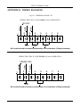
INSTALLATION
To install the Remote Schedule Selector,
•
Remove the RSS from it’s package and locate the four (4) conductor connector (upper left) and the
dip switch (bottom center) on the back of the circuit board.
•
Set the hidden Address Selector dip switch to match the Master’s Programmed Address (default =
Code 65) and the Master Clock’s baud rate. You accomplish this by sliding the dip switches
towards the legend on the circuit board.
The Baud Rate is selected with switch 1. Slide it towards the bottom of the board to select
9600 baud (default) and up to select 2400 baud.
To select the address, total up the
numbers below the switches to arrive
at the total which equals the addess
you wish and slide those switches
down. For example, the default
address is 065. Switch 2 (value of 64)
and switch 8 (value of 1) are down.
(64+1 = 65) For address 003, you
would slide switch 7 and switch 8
down (2+1=3). For address 102, you
would slide down switches 2, 3, 6 and
7. (64+32+4+2=102)
ON
2400
9600
1
2
4
8
16
32
64
BAUD
1 2 3 4 5 6 7 8
•
Attach the Communication Cable wire-pair (with proper polarity). The upper
contector is Data - and the next one down is Data + .
•
Connect a low-voltage Power to the lower 2 terminals on the Terminal Block. The LTR-RSS
requires a voltage source of between 9 and 24 Volts, AC or DC. Note: It is recommended that you
use a power supply other than the power supplied from terminals 12 and 13 of the Communications
Terminals on the back of the Master Clock’s Display Unit. This provides 12 Volts AC at 250ma.
Wire runs of greater than 100 feet or placed in areas that may cause electrical interferances will
cause problems.We also recommend that you place an in-line 250ma fuse on this connection.
•
Secure the cover-plate to the electrical box with four 6-32 FH screws.
51
DD+
~
~
LTRx-512 Installer’s Guide
Connecting the LTR-RSS
INSTALLATION DETAIL
52
LTRx-512 Installer’s Guide
Connecting the LTR-RSS
OPERATIONAL DESCRIPTION
To use the Remote Schedule Selector, the Operator will first select, via the Rotary Switch, which of the
Schedules is to be made active.
The ‘OFF’ position may be used to de-activate all schedules
Positions ‘1’ to ‘8’ may be used to select a single Schedule to be made ‘Active’
The ‘INQUIRE’ position may be used to determine which Schedules may be currently ‘Active’
without altering those schedules previously selected.
After setting the selected position of the Rotary Switch, the Operator should press the ‘ENTER
SELECTION’ Push-Button. This will transmit the appropriate Command to the Master. It will wait for
a reply from the Master, display which Schedule(s) are now Active on the Lighting Indicators (LEDs)
as confirmation to the Operator that the Command has been accepted and executed by the Master. The
lit Indicators will remain active for a period of five (5) seconds, after which the unit will go back to
‘sleep mode’, to conserve power.
53
LTRx-512 Installer’s Guide
Connecting the LTR-GPS Satellite Receiver/Synchronizer
APPENDIX G – Connecting the LTR-GPS Satellite Receiver /
Synchronizer
Lathem’s LTR-GPS is a Global Positioning Satellite receiver using 12-channels to access the accurate
date and time signal transmitted each second by 24 satellites in geosynchronous orbit around the globe.
The package includes an amplified GPS Antenna, which must be mounted out-doors or beneath a roof
sky-light, facing skyward. An integrated cable links the Antenna to the LTR-GPS Receiver Module,
which should be mounted in-doors.
The Receiver Module verifies and reformats the received satellite data, and offers multiple
synchronization protocol outputs, including a capability to synchronize LTRx-512 Master Clocks to this
highly accurate “Atomic” reference.
Simple DIP-Switch set-up enables the installer to specify Local Time Zone, Daylight Savings Time
corrections, and output formats. An LED indicator shows Signal Reception / Protocol Mode.
Unshielded Twisted-Pair (UTP) Cable (Cat-3 or Cat-5) is suitable to connect the D+/D- Data Output
Terminals of the LTR-GPS to the D+/D- “Sync-In” Terminals on the back of the Master Clock’s Front
Panel Assembly.
The LTR-GPS may receive its power from an LTRx-512-series Master Clock, using a 2nd cable pair (as
illustrated below), if the distance is less than 200ft; else, power is provided locally by a 9vAC Power
Adapter.
4 000 FT. M AX
2 00 FT. M AX;
ELSE USE POWER ADAPTER
54
LTRx-512 Installer’s Guide
Power Supply Schematics
APPENDIX H – POWER SUPPLY SCHEMATICS
LTR8-512 / LTR8-512M
LTR4-512
(C) 2000 LATHEM TIME CORP.
VMM7086 REV. D
C5
D12
K7
K8
K6
D4
D3
D5
D6
K5
K6
K7
D6
D5
D4
D3
K8
55
K5
D11
D10
D9
D12
D11
D10
D9
K4
K3
C3
C3
K2
C4
C4
C5
K1
(C) 2000 LATHEM TIME CORP.
VMM7086 REV. D
LTRx-512 Installer’s Guide
Power Supply Schematics
FOR UNITS EQUIPPED WITH AN INTERNAL MODEM
NOTICE: This equipment complies with Part 68 of the FCC Rules. On the mounting panel of this equipment is a label that contains, among other
information, the FCC Registration Number and Ringer Equivalence Number (REN) for this equipment. If requested, provide this information to your
Telephone Company.
The registration jack USOC for this equipment is (RJ-11). An FCC compliant telephone cord and modular plug is provided with this equipment. This
equipment is designed to connect to the telephone network or premises wiring using a compatible modular jack, which is Part 68 compliant. See installation
instructions for details.
The REN is useful to determine the quantity of devices that may be connected to the telephone line. Excessive RENs on the telephone line may result in the
devices not ringing in response to an incoming call. In most, but not all areas, the sum of “REN” of all devices should not exceed five (5). To be certain of the
number of devices that may be connected to a line, as determined by the total “REN”, contact the local Telephone Company.
If your telephone equipment (Modem) causes harm to the telephone network, the Telephone Company will notify you in advance that temporary discontinuance
of service may be required, but if advance notice isn’t practical, you will be notified as soon as possible. You will be advised of your right to file a complaint
with the FCC if you believe it is necessary.
Your Telephone Company may make changes in its facilities, equipment, operations or procedures that could affect the operation of your equipment. If they do,
you will be given advance notice so as to give you an opportunity to maintain uninterrupted service.
If you experience trouble with this equipment (Modem), please contact Lathem Time Customer Service at (800) 241-4990 for repair/warranty information. If
your equipment is causing harm to the telephone network, the Telephone Company may request that you disconnect the equipment until the problem is
resolved.
A Lathem-Authorized Service Center will replace a defective Lathem Modem product.
This equipment may not be used on public coin service provided by the Telephone Company. Connection to party lines is subject to state tariffs. (Contact your
state public utility commission or corporation commission for information.)
NOTICE: The Industry Canada label identifies certified equipment. This certification means that the equipment meets certain telecommunications
network protective, operational and safety requirements. The Industry Canada does not guarantee the equipment will operate to the user’s
satisfaction.
Before installing this equipment, users should ensure that it is permissible to be connected to the facilities of the local Telecommunications Company. This
equipment must also be installed using an acceptable method of connection. In some cases, the company’s inside wiring associated with a single line individual
service may be extended by means of a certified connector assembly (telephone extension cord). The customer should be aware that compliance with the above
conditions may not prevent degradation of service in some situations.
Any equipment repairs made by the user, or equipment malfunctions, may give the Telecommunications Company cause to request the user to disconnect the
equipment.
Users should ensure, for their own protection, that the electrical ground connections of the power utility, telephone lines and internal metallic water pipe system,
if present, are connected together. This precaution may be particularly important in rural areas.
Caution: Users should not attempt to make such connections themselves, but should contact the appropriate electric inspection authority, or electrician, as
appropriate.
NOTE: The Ringer Equivalence Number (REN) assigned to each terminal device provides an indication of the maximum number of terminals allowed to be
connected to a telephone interface. The termination of an interface may consist of any combination of devices subject only to the requirement that the sum of the
Ringer Equivalence Numbers of all the devices does not exceed 5.
A NOTE ABOUT THE LITHIUM BATTERY
This product's lithium battery contains Perchlorate Material - special handling may apply. Please go to web site
www.dtsc.ca.gov/hazardouswaste/perchlorate for information about proper methods of disposal in California.
56
LTRx-512 Installer’s Guide
Power Supply Schematics
Limited One-Year Limited Warranty
Lathem warrants the hardware products described in this guide against defects in material and workmanship for a
period of one year from date of original purchase from Lathem or from an authorized Lathem reseller. The
conditions of this warranty and the extent of the responsibility of Lathem Time Corporation (“Lathem”) under this
warranty are listed below.
1.
2.
3.
4.
5.
6.
7.
8.
9.
This warranty will become void when service performed by anyone other than an approved Lathem
warranty service dealer results in damage to the product.
This warranty does not apply to any product which has been subject to abuse, neglect, or accident, or which
has had the serial number altered or removed, or which has been connected, installed, adjusted, or repaired
other than in accordance with instructions furnished by Lathem.
This warranty does not cover dealer labor cost for removing and reinstalling the machine for repair, or any
expendable parts that are readily replaced due to normal use.
The sole responsibility of Lathem under this warranty shall be limited to repair of this product, or
replacement thereof, at the sole discretion of Lathem.
If it becomes necessary to send the product or any defective part to Lathem or any authorized service
dealer, the product must be shipped in its original carton or equivalent, fully insured with shipping charges
prepaid. Lathem will not assume any responsibility for any loss or damage incurred in shipping.
WARRANTY DISCLAIMER AND LIMITATION OF LIABILITY: Except only the limited express
warranty set forth above, the products are sold with no expressed or implied warranties of any kind, and the
implied warranties of merchantability and fitness for a particular purpose are hereby expressly disclaimed.
No warranties are given with respect to products purchased other than from Lathem or an authorized
Lathem reseller and any such products are purchased "as is, with all faults." In no event will Lathem be
liable for any direct, indirect, special, incidental or consequential damages arising out of or in connection
with the delivery, use or inability to use, or performance of this product. In the event any limited remedy
given herein shall be deemed to have failed of its essential purpose, Lathem's maximum liability shall be to
refund the purchase price upon return of the product.
Proof of date of purchase from Lathem or an authorized Lathem reseller is required for warranty service on
this product.
This Warranty grants specific legal rights. Additional legal rights, which may vary by locale, may also
apply.
Should any difficulties arise with the performance of this product during warranty, or with any Lathem
authorized service centers, contact Lathem Time at the address below.
Lathem Time
200 Selig Drive, SW, Atlanta, GA 30336
404-691-0405
www.lathem.com
Copyright © 2007 Lathem Time Corporation. All rights reserved.
57
LTRx-512 Installer’s Guide
Power Supply Schematics
A
Administrator password...................... 11, 17, 18, 19, 20
Auto Bell Test ......................................................15, 22
B
Baud Rate.............................................................16, 17
Bell schedules................................................... 1, 18, 19
Bell zones...................................................................11
C
Cable connection ..........................................................2
Change Password .................................................18, 20
Change Schedule ........................................................19
Clock sync control ......................................................11
Clock type codes.........................................................18
Clock types.............................................................1, 18
Communications........................1, 15, 16, 18, 20, 23, 47
Communications function...........................................20
Country code .................................................. 15, 17, 19
D
Daylight savings......................................... 1, 15, 17, 19
Disable circuits.....................................................13, 19
E
Enable circuits................................................ 13, 18, 19
F
Function [0] – Password .......................................11, 17
Function [1] – Set Date and Time .........................12, 18
Function [2] – Select Clock Control......................13, 18
Function [3] – Manual Bell Control ......................14, 18
Function [4] – Program Schedule................................18
Function [5] – Schedule Change .................................19
Function [6] – Enable/Disable Circuits .................13, 19
Function [7] – Daylight Savings Time ..................15, 19
Function [8] – Change Schedule .................................19
Function [9] – Sync Clocks.........................................20
Function [A] – Program Holidays ...............................20
Function [B] – Communications ...........................15, 20
Function [C] – Change Password................................20
H
Hidden codes ........................................................15, 22
Hidden power supply ..............................................7, 47
Holiday schedules .............................................1, 17, 20
L
Lights ...................................................................14, 18
LTR MasterLink software................. 1, 2, 15, 19, 20, 47
M
Manual bell control...................................................... 1
P
Passwords................................................... 1, 11, 17, 20
Program Holidays function .........................................20
Program Keys .............................................................17
Q
Quick Check Command [*] ........................................17
Quick Check Command [1] ........................................17
Quick Check Command [3] ........................................17
Quick-connects ............................................................ 2
R
Rack mount ................................................................. 6
RS-485 network.........................1, 11, 13, 15, 23, 45, 47
S
Schedule Changes function .........................................19
Schedules .............................................................18, 19
Semi-flush mount ........................................................ 4
Set the date and time ..................................................18
Surface mount ............................................................. 3
Sync Clocks function ..................................................20
Syncing Clocks............................................... 11, 13, 23
T
Terminal block ...........................................................47
Terminal ID#........................................................16, 17
Test circuits ..........................................................14, 18
U
User password .......................................... 11, 17, 18, 20
58